

lg LGAV410 OWNER’S MANUAL

Audio/Video Surround
RECEIVER
OWNER’S MANUAL
MODEL : LGAV410
Before connecting up, operating or repairing this product,
please read this instruction booklet carefully and completely.
This lightning flash with arrowhead symbol within an
equilateral triangle is intended to alert the user to
the presence of uninsulated dangerous voltage
within the product’s enclosure that may be of
sufficient magnitude to constitute a risk of electric
shock to persons.
The exclamation point within an equilateral triangle
is intended to alert the user to the presence of
important operating and maintenance (servicing)
instructions in the literature accompanying the
appliance.
WARNING: Do not install this equipment in a confined space
such as a book case or similar unit.
CAUTION: The apparatus shall not be exposed to water,
dripping or splashing and that no objects filled with liquids,
such as vases, shall be placed on the apparatus.
CAUTION concerning the Power Cord
Most appliances recommend they be placed upon a
dedicated circuit;
That is, a single outlet circuit which powers only that appliance
and has no additional outlets or branch circuits. Check the
specification page of this owner's manual to be certain.
Do not overload wall outlets. Overloaded wall outlets, loose or
damaged wall outlets, extension cords, frayed power cords, or
damaged or cracked wire insulation are dangerous. Any of
these conditions could result in electric shock or fire.
Periodically examine the cord of your appliance, and if its
appearance indicates damage or deterioration, unplug it, discontinue use of the appliance, and have the cord replaced with
an exact replacement part by an authorized servicer.
Protect the power cord from physical or mechanical abuse,
such as being twisted, kinked, pinched, closed in a door, or
walked upon. Pay particular attention to plugs, wall outlets, and
the point where the cord exits the appliance.
REGULATORY INFORMATION:
FCC Part 15
This product has been tested and found to comply with the
limits for a Class B digital device, pursuant to Part 15 of the
FCC Rules. These limits are designed to provide reasonable
protection against harmful interference when the product is
operated in a residential installation. This product generates,
uses and can radiate radio frequency energy and, if not
installed and used in accordance with the instruction manual,
may cause harmful interference to radio communications.
However, there is no guarantee that interference will not occur
in a particular installation. If this product does cause harmful
interference to radio or television reception, which can be
determined by turning the product off and on, the user is
encouraged to try to correct the interference by one or more
of the following measures:
• Reorient or relocate the receiving antenna.
• Increase the separation between the product and receiver.
• Connect the product into an outlet on a circuit different
from that to which the receiver is connected.
• Consult the dealer or an experienced radio/TV technician
for help.
FCC WARNING: This equipment may generate or use radio
frequency energy. Changes or modifications to this equipment
may cause harmful interference unless the modifications are
expressly approved in the instruction manual. The user could
lose the authority to operate this equipment if an unauthorized
change or modification is made.
FCC COMPLIANCE: The responsible party for this product’s
compliance is:
LG Electronics U.S.A., Inc. 1000 Sylvan Avenue
Englewood Cliffs, NJ 07632, USA
Phone: 1-201-816-2125.
SERIAL NUMBER: The serial number is found on the back of
this unit. This number is unique to this unit and not available to
others. You should record requested information here and
retain this guide as a permanent record of your purchase.
Model No.
Serial No.
2
Safety Precautions
WARNING: TO REDUCE THE RISK OF FIRE OR ELEC-
TRIC SHOCK, DO NOT EXPOSE THIS PRODUCT TO
RAIN OR MOISTURE.
CAUTION
RISK OF ELECTRIC SHOCK
DO NOT OPEN
WARNING: TO REDUCE THE RISK
OF ELECTRIC SHOCK,
DO NOT REMOVE COVER (OR BACK)
NO USER-SERVICEABLE PARTS INSIDE
REFER SERVICING TO QUALIFIED SERVICE
PERSONNEL.
FA-2100AAA1UZLK

INTRODUCTION
3
1. Read these instructions. - All these safety and
operating instructions should be read before the
product is operated.
2. Keep these instructions. - The safety, operating
and use instructions should be retained for future
reference.
3. Heed all warnings. - All warnings on the product
and in the operating instructions should be adhered
to.
4. Follow all instructions. - All operating and use
instructions should be followed.
5. Do not use this apparatus near water. – For
example: near a bath tub, wash bowl, kitchen sink,
laundry tub, in a wet basement; or near a swimming
pool; and like.
6. Clean only with dry cloth. – Unplug this product
from the wall outlet before cleaning. Do not use
liquid cleaners.
7.
Do not block any ventilation openings. Install in
accordance with the manufacturer’s instructions. -
Slots and openings in the cabinet are provided for
ventilation and to ensure reliable operation of the
product and to protect it from over- heating.
The openings should never be blocked by placing
the product on a bed, sofa, rug or other similar
surface. This product should not be placed in a
built-in installation such as a bookcase or rack
unless proper ventilation is provided or the
manufacturer’s instructions have been adhered to.
8. Do not install near any heat sources such as
radiators, heat registers, stoves, or other
apparatus (including amplifiers) that produce
heat.
9.
Do not defeat the safety purpose of the polarized
or grounding-type plug. A polarized plug has two
blades with one wider than the other. A grounding
type plug has two blades and a third grounding prong. The wide blade or the third prong are
provided for your safety. If the provided plug
does not fit into your outlet, consult an electrician for replacement of the obsolete outlet.
10. Protect the power cord from being walked on or
pinched particularly at plugs, convenience
receptacles, and the point where they exit from
the apparatus.
11. Only use attachments/accessories specified by
the manufacturer.
12. Use only with the cart, stand, tripod, bracket, or
table specified by the manufacturer, or sold with
apparatus. When a cart is used, use caution
when moving the cart/apparatus combination to
avoid injury from tip-over.
13. Unplug this apparatus during lightning storms
or when unused for long periods of time.
14.
Refer all servicing to qualified service personnel.
Servicing is required when the apparatus has
been damaged in any way, such as powersupply cord or plug is damaged, liquid has
been spilled or objects have fallen into the
apparatus, the apparatus has been exposed to
rain or moisture, does not operate normally, or
has been dropped.
CAUTION: PLEASE READ AND OBSERVE ALL WARNINGS AND INSTRUCTIONS IN THIS OWNER’S MANU-
AL AND THOSE MARKED ON THE UNIT. RETAIN THIS MANUAL FOR FUTURE REFERENCE.
This set has been designed and manufactured to assure personal safety. Improper use can result in electric shock
or fire hazard. The safeguards incorporated in this unit will protect you if you observe the following procedures for
installation, use, and servicing.
This unit does not contain any parts that can be repaired by the user.
DO NOT REMOVE THE CABINET COVER, OR YOU MAY BE EXPOSED TO DANGEROUS VOLTAGE. REFER
SERVICING TO QUALIFIED SERVICE PERSONNEL ONLY.
IMPORTANT SAFETY INSTRUCTIONS

4
Table of Contents
Introduction
Safety Precautions . . . . . . . . . . . . . . . . . . . . . . . . . 2
Important Safety Instructions . . . . . . . . . . . . . . . . . 3
Table of Contents . . . . . . . . . . . . . . . . . . . . . . . . . . 4
System Connections . . . . . . . . . . . . . . . . . . . . . . 5-8
Front Panel Controls. . . . . . . . . . . . . . . . . . . . . . . . 9
Universal Remote Controls . . . . . . . . . . . . . . . 10-13
Function Table of the Numbered Buttons . . . . . . 11
Operating Components with Remote Control . . . 12
Loading Batteries. . . . . . . . . . . . . . . . . . . . . . . . 12
Remote Control Operation Range . . . . . . . . . . . 12
Entering a Setup Code . . . . . . . . . . . . . . . . . . . 13
OPERATION
Listening to a program. . . . . . . . . . . . . . . . . . . 14-16
Before Operation . . . . . . . . . . . . . . . . . . . . . . . . 14
When CD, TAPE MON or VIDEO 1 ~ VIDEO 4 is . . .
selected
. . . . . . . . . . . . . . . . . . . . . . . . . . . . . . . 15
Adjusting the Tone(Bass and Treble). . . . . . . 15-16
Surround Sound. . . . . . . . . . . . . . . . . . . . . . . . 17-19
Surround Modes . . . . . . . . . . . . . . . . . . . . . . 17-18
Speaker Placement . . . . . . . . . . . . . . . . . . . . . . 19
Enjoying Surround Sound . . . . . . . . . . . . . . . . 20-22
Adjusting each Channel Level . . . . . . . . . . . . . . 22
Adjusting each Channel Level with Test Tone. . . 22
Downmixing into 2 front channels. . . . . . . . . . . . 22
Listening to Radio . . . . . . . . . . . . . . . . . . . . . . 23-24
Auto Tuning. . . . . . . . . . . . . . . . . . . . . . . . . . . . 23
Manual Tuning. . . . . . . . . . . . . . . . . . . . . . . . . . 23
Preset Radio Stations . . . . . . . . . . . . . . . . . . . . 23
Tuning to Preset Stations. . . . . . . . . . . . . . . . . . 24
Scanning Preset Stations in Sequence . . . . . . . . 24
Recording . . . . . . . . . . . . . . . . . . . . . . . . . . . . . 25-26
Recording with Tape Monitor . . . . . . . . . . . . . . . 25
Dubbing from Video Components onto VIDEO 1 25
Dubbing the Sound and Image Signals Separately
onto VIDEO 1 . . . . . . . . . . . . . . . . . . . . . . . . . . 25
Digital Audio Recording with MD Recorder. . . . . 26
Other Functions . . . . . . . . . . . . . . . . . . . . . . . . 27-28
Compressing the Dynamic Range (Dolby Digital
sources only) . . . . . . . . . . . . . . . . . . . . . . . . . . 27
Operating the Sleep Timer . . . . . . . . . . . . . . . . . 27
Adjusting the Brightness of the Fluorescent
Displays . . . . . . . . . . . . . . . . . . . . . . . . . . . . . . . 27
Entering a Video Label . . . . . . . . . . . . . . . . . . . . 28
Correcting or Clearing a Video Label . . . . . . . . . 28
Room 2 Source Playback . . . . . . . . . . . . . . . . . . . 29
Using the OSD. . . . . . . . . . . . . . . . . . . . . . . . . . . . 30
Current States Display . . . . . . . . . . . . . . . . . . . 30
OSD Menu Settings . . . . . . . . . . . . . . . . . . . . . 31-32
Setting the Speaker Setup . . . . . . . . . . . . . . . . . 31
When selecting the Speaker Config . . . . . . . . . . 31
When selecting the Speaker Distance . . . . . . . . 32
When selecting the LFE Level Control . . . . . . . . 32
Setting the Function Select . . . . . . . . . . . . . . . 33-34
When selecting the Input Setup . . . . . . . . . . . . . 33
When selecting the Tone Control . . . . . . . . . . . . 34
When selecting the OSD Mode . . . . . . . . . . . . . 34
Setting the Surround Setup . . . . . . . . . . . . . . . 35-36
When selecting the Source Direct . . . . . . . . . . . 35
When selecting the CINEMA EQ . . . . . . . . . . . . 35
When selecting the Decoding Mode . . . . . . . . . . 35
When selecting the Surround Mode . . . . . . . . . . 36
Setting the CH Level Trim. . . . . . . . . . . . . . . . . . . 37
Setting the Room 2 Feed Setup. . . . . . . . . . . . 37-38
When selecting the Volume Mode . . . . . . . . . . . 37
When selecting the Function Select for
ROOM 2 . . . . . . . . . . . . . . . . . . . . . . . . . . . . . . 38
REFERENCE
Troubleshooting Guide. . . . . . . . . . . . . . . . . . . 39-40
Specifications. . . . . . . . . . . . . . . . . . . . . . . . . . 41-42
INTRODUCTION
5
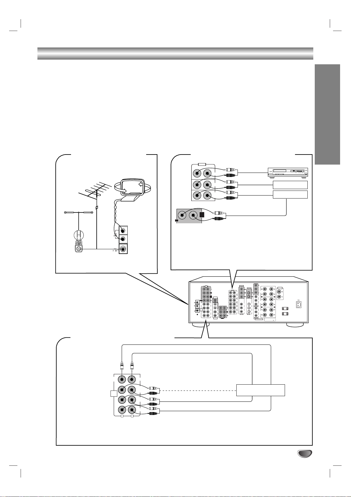
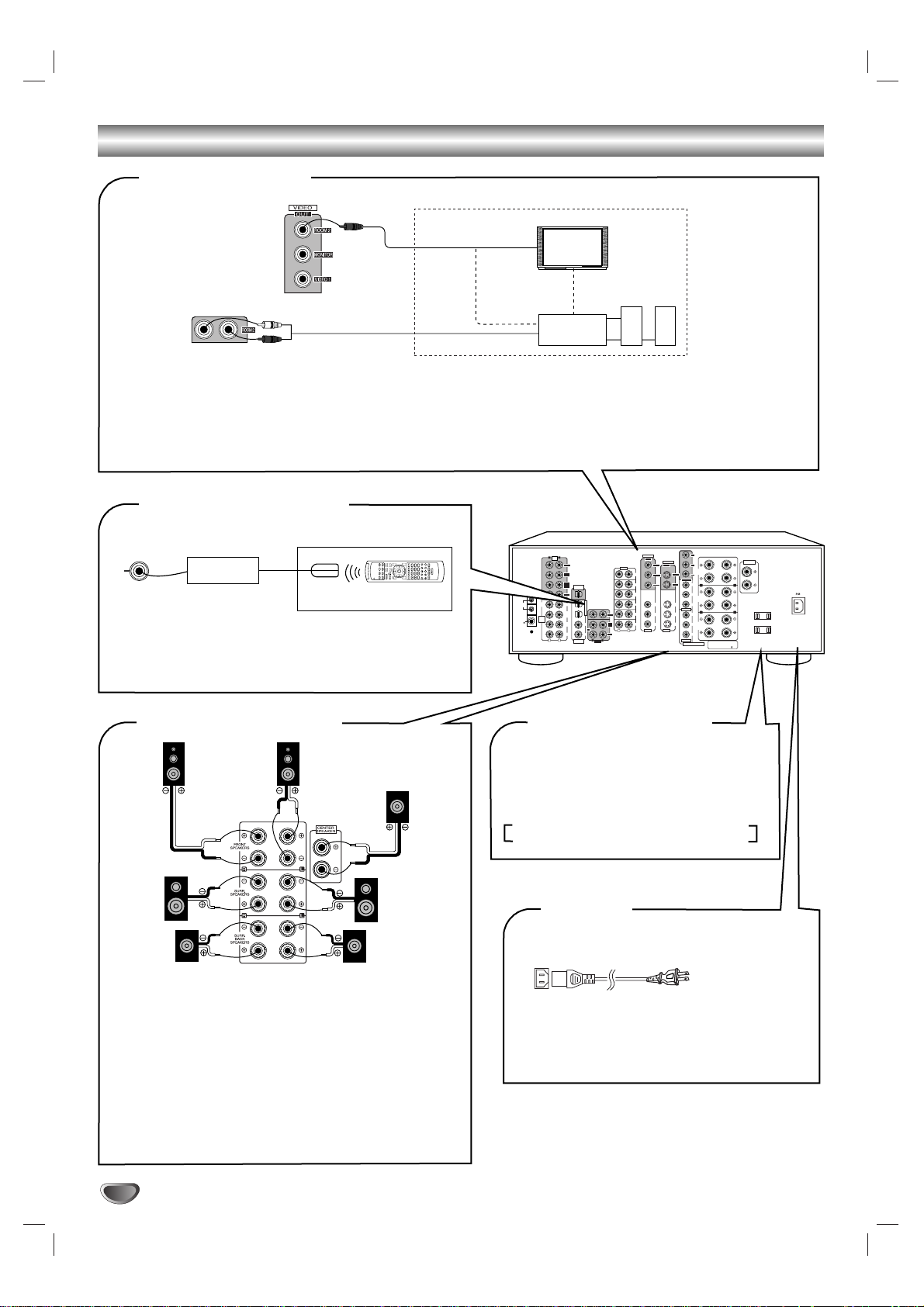
System Connections
l
Do not connect the receiver to the wall AC outlet when plugging and unplugging connection cords.
l Be sure to connect the white RCApin cords to the L(left) and the red RCA pin cords to the R(right) jacks when making-
connections.
l Change the position of the FM indoor antenna until you get the best reception of your favorite FM stations.
l A75Ω outdoor FM antenna may be used to further improve the reception.
Disconnect the indoor antenna before replacing it with the outdoor one.
l Place the AM loop antenna as far as possible from the receiver, TV set, speaker cords and the AC input cord and
set it to a direction for the best reception.
l If the reception is poor with the AM loop antenna, an AM outdoor antenna can be used in place of the AM loop
antenna.
l Make connections firmly and correctly. If not, poor connections can cause loss of sound, noise or damage to the
receiver.
l If the electricity fails or the AC input cord is left unplugged for about two weeks, the memorized contents will be cleared.
Should this happen, all settings and memorized stations will need to be reprogrammed.
FM
(OUTDOOR ANTENNA)
AM loop antenna
FM
(INDOOR ANTENNA)
300 ohm
feeder
75 ohm
ADAPTOR
POWER
REMOTE SENSOR
PROGRAM/REVIEW
RANDOM REPEAT
OPEN/CLOSE
PHONES LEVEL
PHONES
MIN MAX
ON/OFF
12 3 45
GRAPHICSPEAK DELETEEDIT
SCENETRACK
INDEXSTEP
AB
V-CDPBCREVERT PROGAUTO RANDOMREPEAT ALL1DISCS
123
456
789
101112
131415
MPXINTROA< >B
TAPE
MON.
REC
CD
AUX
TAPE
MON.
IN
CD player
Additional
audio component
Tape deck or
MD recorder
PLAY(LINE OUT)
REC(LINE IN)
xx
CONNECTING AUDIO COMPONENTS
l The AUX jacks may be connected to an additional audio
component such as CD player or tape deck, etc.
l Connect the TAPE MON. IN/OUT jacks to the PLAY(LINE
OUT)/REC(LINE IN) jacks of tape deck, MD recorder or CD
recorder.
l The TAPE MON. IN/OUT jacks may also be connected to
the LINE OUT/IN jacks of an optional graphic equalizer.
xx
CONNECTING ANTENNAS
7.1CH
DIRECT
INPUT
FRONT
CENTER
SUR-
ROUND
SUB
WOOFER
SUR-
ROUND
BACK
R
L
SUBWOOFER CH OUT
CENTER CH OUT
Decoder with 5.1
or 7.1 channel output
SURROUND BACK CH OUT
SURROUND CH OUT
FRONT CH OUT
xx
CONNECTING 7.1CH DIRECT INPUTs
l Use these jacks to connect the corresponding analog outputs of a DVD player or external decoder, etc. that has 5.1
or 7.1 channel outputs.
l In case of 5.1 channel outputs, do not connect these SURROUND BACK inputs to your audio component. ( For
details, refer to the operating instructions of the component to be connected.)
PRE
R
L
OUT
FRONT
SUR-
ROUND
SUR-
ROUND
OPTICAL
BACK
OUT
SUB
CENTER
WOOFER
AM
WOOFER
LOOP
FM
75
ANTENNA
OPTICAL IN
SUB
CENTER
OPT 1
SURROUND
BACK
7.1CH
DIRECT
OPT 2
INPUT
SUR-
COAX1
ROUND
REC
FRONT
COAX2
COAXIAL
L
R
L
IN
OUT
VIDEO
IN
CD
AUX
TAPE
MON.
VIDEO 1
ROOM 2
VIDEO 2
TAPE
VIDEO 3
MON.
R
L
VIDEO 1
R
Y
OUT
S-VIDEO
OUT
C
B
ROOM 2
FRONT
SPEAKERS
MONITOR
C
R
MONITOR
MONITOR
Y
VIDEO 1
VIDEO 1
B
C
SURR.
SPEAKERS
VIDEO 1
VIDEO 1
C
R
VIDEO 1
VIDEO 2
Y
VIDEO 2
SURR.
VIDEO 3
VIDEO 3
B
C
BACK
SPEAKERS
IN
IN
C
R
VIDEO 2
COMPONENT
R
R
FRONT , CENTER , SURROUND,
SURROUND BACK : 6 OHMS( ) MIN.
SPEAKER IMPEDANCE
CENTER
SPEAKER
L
AC OUTLET
L
SWITCHED
120V~60Hz
TOTAL 100W 1A MAX
AC INLET
120V~60Hz
3.5A
6
System Connections
POWER
ON/OFF
MULTIPLE COMPACT DISC PLAYER CDC-5080R
POWER
12345
DISC SKIP
REMOTE SENSOR
PROGRAM/REVIEW
RANDOM REPEAT
OPEN/CLOSE
PHONES LEVEL
PHONES
MIN MAX
ON/OFF
MULTIPLE COMPACT DISC PLAYER CDC-5080R
5 DISC
PLAY EXCHANGE
Play 1 Exchange 4
AUTOMATIC DISC LOADING SYSTEM
12 34 5
GRAPHICSPEAKDELETE EDIT
SCENETRACK
INDEXSTEP
AB
V-CDPBCREVERTPROG AUTO RANDOMREPEATALL1DISCS
123
456
789
101112
131415
MPXINTROA< >B
REC
Y
C
B
C
R
Y
C
B
C
R
COMPONENT
C
B
Y
C
R
MONITOR
VIDEO 2
VIDEO 3
S-VIDEO
VIDEO 1
OUT
IN
VIDEO 1
VIDEO 2
MONITOR
VIDEO 1
VIDEO 2
VIDEO 3
MONITOR
VIDEO 1
VIDEO
OUT
IN
ROOM 2
VIDEO 1
OUT
VIDEO 1
R
L
VIDEO 3
VIDEO 1
VIDEO 2
R
L
POWER
OPEN/CLOSE
PHONES LEVEL
PHONES
MIN MAX
ON/OFF
MULTIPLE COMPACT DISC PLAYER CDC-5080R
1 23 45
GRAPHICSPEAK DELETEEDIT
SCENETRACK
INDEXSTEP
AB
V-CDPBCREVERT PROGAUTO RANDOMREPEATALL1DISC S
123
456
789
101112
131415
MPXINTROA< >B
COMPONENT VIDEO OUT
AUDIO
PLAY(OUT)
AUDIO
REC(IN)
S-VIDEO IN
VIDEO IN
S-VIDEO OUT
VIDEO OUT
Video deck or
additonal
video component
VIDEO IN
Monitor TV
S-VIDEO IN
COMPONENT VIDEO IN
Green
Blue
Red
Green
Blue
Red
Green
Blue
Red
COMPONENT
S-VIDEO OUT
S-VIDEO OUT
VIDEO OUT
AUDIO OUT
VIDEO OUT
AUDIO OUT
DVD player
LD player or additonal
video component
VIDEO OUT
xx
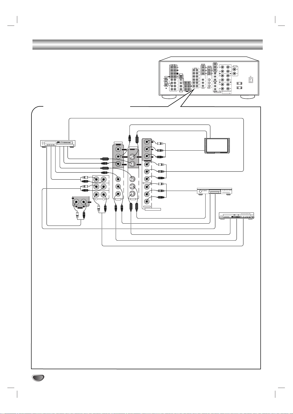
CONNECTING VIDEO COMPONENTS
l The VIDEO 1 jacks may also be connected to a DVD recorder or other digital video recording component.
For details, refer to the operating instructions of the component connected.
l There are three kinds of video jacks (COMPONENT, S, normal (composite)) for connecting the video components,
according to the built-in jacks of them, connect them to the corresponding VIDEO jacks (VIDEO 1~3) respectively.
l The VIDEO 2(or VIDEO 3) jacks may also be connected to an additional video component such as a video deck, a
cable TV tuner, an LD player or satellite system.
l This unit incorporates COMPONENT as well as S and normal(composite) VIDEO jacks.
l For your reference, the excellence in picture quality is as follows: "COMPONENT" > "S-VIDEO"> "VIDEO".
l When making COMPONENT VIDEO connections, connect "Y" to "Y", "CB" to "CB" (or "B-Y", "PB") and "CR" to
"CR"(or "R-Y", "PR").
l Signals input into the COMPONENT VIDEO IN jacks will be output in only the MONITOR COMPONENT VIDEO
OUT jacks.
l A signal input into the normal(composite) VIDEO IN jack will be output in the normal(composite) VIDEO OUT jacks
and a signal input into the S-VIDEO IN jack will be output in the S-VIDEO OUT jacks.
xx
Note: :
l The on-screen display function and recording the component video signals are not available when using the COM-
PONENT VIDEO connections.
Y
PRE
R
L
OUT
FRONT
SUR-
ROUND
SUR-
ROUND
OPTICAL
BACK
OUT
SUB
CENTER
WOOFER
AM
WOOFER
LOOP
FM
75
ANTENNA
OPTICAL IN
SUB
CENTER
OPT 1
SURROUND
BACK
7.1CH
DIRECT
OPT 2
INPUT
SUR-
COAX1
ROUND
REC
FRONT
COAX2
COAXIAL
L
R
L
IN
OUT
VIDEO
OUT
S-VIDEO
OUT
C
B
ROOM 2
IN
CD
AUX
TAPE
MON.
VIDEO 1
ROOM 2
VIDEO 2
TAPE
VIDEO 3
MON.
IN
R
L
VIDEO 1
R
FRONT
SPEAKERS
MONITOR
C
R
MONITOR
MONITOR
Y
VIDEO 1
VIDEO 1
B
C
SURR.
SPEAKERS
VIDEO 1
VIDEO 1
C
R
VIDEO 1
VIDEO 2
Y
VIDEO 2
SURR.
VIDEO 3
VIDEO 3
B
C
BACK
SPEAKERS
IN
C
R
VIDEO 2
COMPONENT
R
R
FRONT , CENTER , SURROUND,
SURROUND BACK : 6 OHMS( ) MIN.
SPEAKER IMPEDANCE
CENTER
SPEAKER
L
AC OUTLET
L
SWITCHED
120V~60Hz
TOTAL 100W 1A MAX
AC INLET
120V~60Hz
3.5A
INTRODUCTION
7
System Connections
Power amplifier
Power amplifier
Surround speakers
Front speakers
Surround back speakers
Front center speaker
Powered subwoofer
Power amplifier
Power amplifier
xx
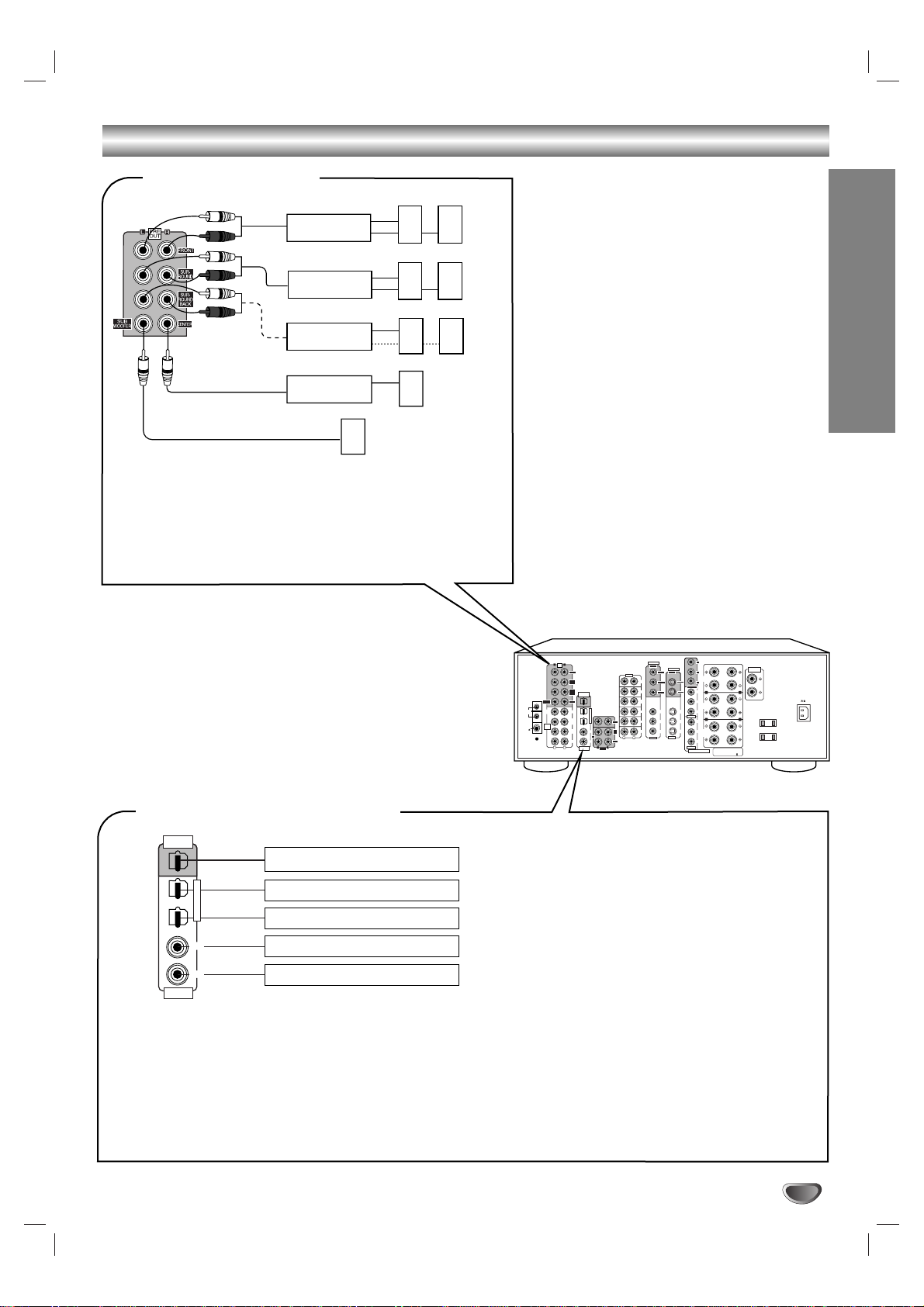
PRE OUT connections
OPT 1
OPT 2
COAX1
COAX2
COAXIAL
IN
OPTICAL IN
OPTICAL
OUT
Component(such as an MD recorder,
CD recorder) with OPTICAL DIGIAL IN
Component with
OPTICAL DIGITAL OUT
Component with
OPTICAL DIGITAL OUT
Component with
COAXIAL DIGITAL OUT
Component with
COAXIAL DIGITAL OUT
xx
CONNECTING DIGITAL INs and OUT
l The COAXIALor the OPTICAL DIGITAL OUTs of the components
that are connected to CD, TAPE MONITOR and VIDEO 1 VIDEO 4 of this unit can be connected to these DIGITALINs.
l After making digital connections, be sure to match the DIGITAL
INs to the corresponding input source respectively.
(For details, refer to "When selecting the DIGITALIN SETUP" on
page 33.)
l A digital input should be connected to the components
such as LD player, CD player or DVD player, etc.
capable of outputting DTS, Dolby Digital or PCM format digital signals,etc.
l If the component with OPTICAL IN jack is connected
to the OPTICAL OUT jack of this unit, you can record
the high quality sound of CDs etc. without degradation.
l For details, refer to the operating instructions of the
component connected.
l When making the COAXIAL DIGITAL connection, be
sure to use a 75 Ω COAXIAL cord, not a conventional
AUDIO cord.
l All of the commercially available optical fiber cords
cannot be used for the equipment. If there is an optical fiber cord which cannot be connected to your
equipment, consult your dealer or nearest service
organization.
l Use these jacks when adding additional amplifiers.
l Connect the PRE OUT jacks to the powered speakers or the power
amplifiers connected to speakers respectively.
l To emphasize the deep bass sounds, connect a powered subwoofer.
l Only when enjoying 6.1 or 7.1 channel surround playback, make the
surround back connections between the audio equipment.
PRE
R
L
OUT
FRONT
SUR-
ROUND
SUR-
ROUND
OPTICAL
BACK
OUT
SUB
CENTER
WOOFER
AM
WOOFER
LOOP
FM
75
ANTENNA
OPTICAL IN
SUB
CENTER
OPT 1
SURROUND
BACK
7.1CH
DIRECT
OPT 2
INPUT
SUR-
COAX1
ROUND
REC
FRONT
COAX2
COAXIAL
L
R
L
IN
OUT
VIDEO
IN
CD
AUX
TAPE
MON.
VIDEO 1
ROOM 2
VIDEO 2
TAPE
VIDEO 3
MON.
R
L
VIDEO 1
R
Y
OUT
S-VIDEO
OUT
C
B
ROOM 2
FRONT
SPEAKERS
MONITOR
C
R
MONITOR
MONITOR
Y
VIDEO 1
VIDEO 1
B
C
SURR.
SPEAKERS
VIDEO 1
VIDEO 1
C
R
VIDEO 1
VIDEO 2
Y
VIDEO 2
SURR.
VIDEO 3
VIDEO 3
B
C
BACK
SPEAKERS
IN
IN
C
R
VIDEO 2
COMPONENT
R
R
FRONT , CENTER , SURROUND,
SURROUND BACK : 6 OHMS( ) MIN.
SPEAKER IMPEDANCE
CENTER
SPEAKER
L
AC OUTLET
L
SWITCHED
120V~60Hz
TOTAL 100W 1A MAX
AC INLET
120V~60Hz
3.5A
8
System Connections
Another room
VIDEO IN
A/V receiver
or amplifier
VIDEO IN
Monitor TV
Speakers
AUDIO IN
xx
ROOM 2 connections
l If another A/V receiver or integrated amplifier, etc. is connected to these jacks, you can play a different program source
in another room as well as one source in the main room at the same time.(For details, refer to "ROOM 2 SOURCE
PLAYBACK" on page 29).
l When the multi-room adaptor is connected to control this unit in another room, the ROOM 2 function is more convenient.
xx
Note:
l Use high quality connection cords in such a way that there is no humming or noise.
Front right
Surround
right
Surround back
right
Front left
Front center
Surround
left
Surround back
left
xx
CONNECTING SPEAKERS
xx
SWITCHED AC OUTLET
l Never short circuit the + and - speaker wires.
l Be sure to connect speakers firmly and correctly according to
the channel (left and right ) and the polarity ( + and -).
l Be sure to use speakers with the impedance of over 6 Ω.
l Only in case of enjoying either 6.1 or 7.1 channel surround
playback, connect only the surround back left speaker or
both of surround back speakers.
xx
Note:
l After installing the speakers, first set the connected speakers
to the desired before operating this receiver.(For details, refer
to "SETTING THE SPEAKER SETUP" on page 31.)
l To control this unit from a remote location, connect this jack
to the output of the multi-room adaptor.
For information on the multi-room system kit, contact the
Xantech corporation at www.xantech.com.
l This outlet is switched on(power-on mode)
and off(standby mode) according to power
control as follows (Maximum total capacity is
100W):
Standby mode — switched AC outlet off
Power-on mode — switched AC outlet on
To a wall AC
outlet.
xx
AC INLET
Plug the supplied AC input cord into this AC INLET
and then into the wall AC outlet.
l Do not use an AC input cord other than the one
supplied with this unit. The AC input cord supplied
is designed for use with this unit and should not
be used with any other device.
xx
CONNECTING MULTI-ROOM
SYSTEM KIT
OUT
Another room
IR receiver
(Multi-room system kit)
Remote control unit
DVD
VOL.
CH LEVEL
OSD
CH SEL
INTRO
RETURN
DSP
MODE
AUTO
ST
CENTER
MODE
TEST
TONE
DISC
P.SCAN
TUNER
CD
T1/MON AUX
PHONO
VID1 VID2 VID3 VID4 VID5
SYS DISP SLEEP
DIRECT IN
ROOM2
RPT
AB
7.1 SURR
TITLE
ENTER
MULTI
Adaptor
(Multi-room system kit)
Y
VIDEO
OUT
S-VIDEO
OUT
C
B
ROOM 2
IN
CD
AUX
TAPE
MON.
VIDEO 1
ROOM 2
VIDEO 2
TAPE
VIDEO 3
MON.
IN
R
L
VIDEO 1
R
FRONT
SPEAKERS
MONITOR
C
R
MONITOR
MONITOR
Y
VIDEO 1
VIDEO 1
B
C
SURR.
SPEAKERS
VIDEO 1
VIDEO 1
C
R
VIDEO 1
VIDEO 2
Y
VIDEO 2
SURR.
VIDEO 3
VIDEO 3
B
C
BACK
SPEAKERS
IN
C
R
VIDEO 2
COMPONENT
R
R
FRONT , CENTER , SURROUND,
SURROUND BACK : 6 OHMS( ) MIN.
SPEAKER IMPEDANCE
CENTER
SPEAKER
L
AC OUTLET
L
SWITCHED
120V~60Hz
TOTAL 100W 1A MAX
PRE
R
L
OUT
FRONT
SURROUND
SURROUND
OPTICAL
BACK
OUT
SUB
CENTER
WOOFER
AM
WOOFER
LOOP
FM
75
ANTENNA
OPTICAL IN
SUB
CENTER
OPT 1
SUR-
ROUND
BACK
7.1CH
DIRECT
OPT 2
INPUT
SUR-
COAX1
ROUND
REC
FRONT
COAX2
COAXIAL
L
R
L
IN
OUT
AC INLET
120V~60Hz
3.5A
INTRODUCTION
9
Front Panel Controls
Universal Remote Controls
10
xx
Note:
For enhanced Universal Remote Programming instructions and manufacturer’s codes, please refer to the operating manual inclosed with
this Universal Remote Control.
xx
Notes:
l
The setup code for each component must be entered before operation.
l
For setup codes(manufacturer’s codes), please refer to “Set-Up Code Tables” in the operating manual of this remote control.
l
Some operation buttons have different functions according to each operation mode.
l
Be sure to set the remote control to the correct mode before operation.
LED LAMP
VOLUME UP/DOWN( / ) BUTTONS
CHANNEL LEVEL UP/DOWN( / ) BUTTONS
CURSOR CONTROL( , , , ) BUTTONS
DEVICE BUTTONS
POWER BUTTON
ENTER BUTTON
NUMERIC(1~0) BUTTONS
LIGHT BUTTON
To operate the desired component with this remote
control, first select the corresponding DEVICE button.
For selecting preset stations in tuner mode.
For selecting a track or a disc in CD mode, etc.
When selecting a disc, select disc No. (1~5) within 2 sec.
after pressing DISC(marked "P.SCAN") button.
Activates the backlighting of the remote control
for 7 sec. If any other button is pressed while
the backlighting is on, the remote control will
remain backlit for an additional 7 sec.
INTRODUCTION
11
Universal Remote Controls
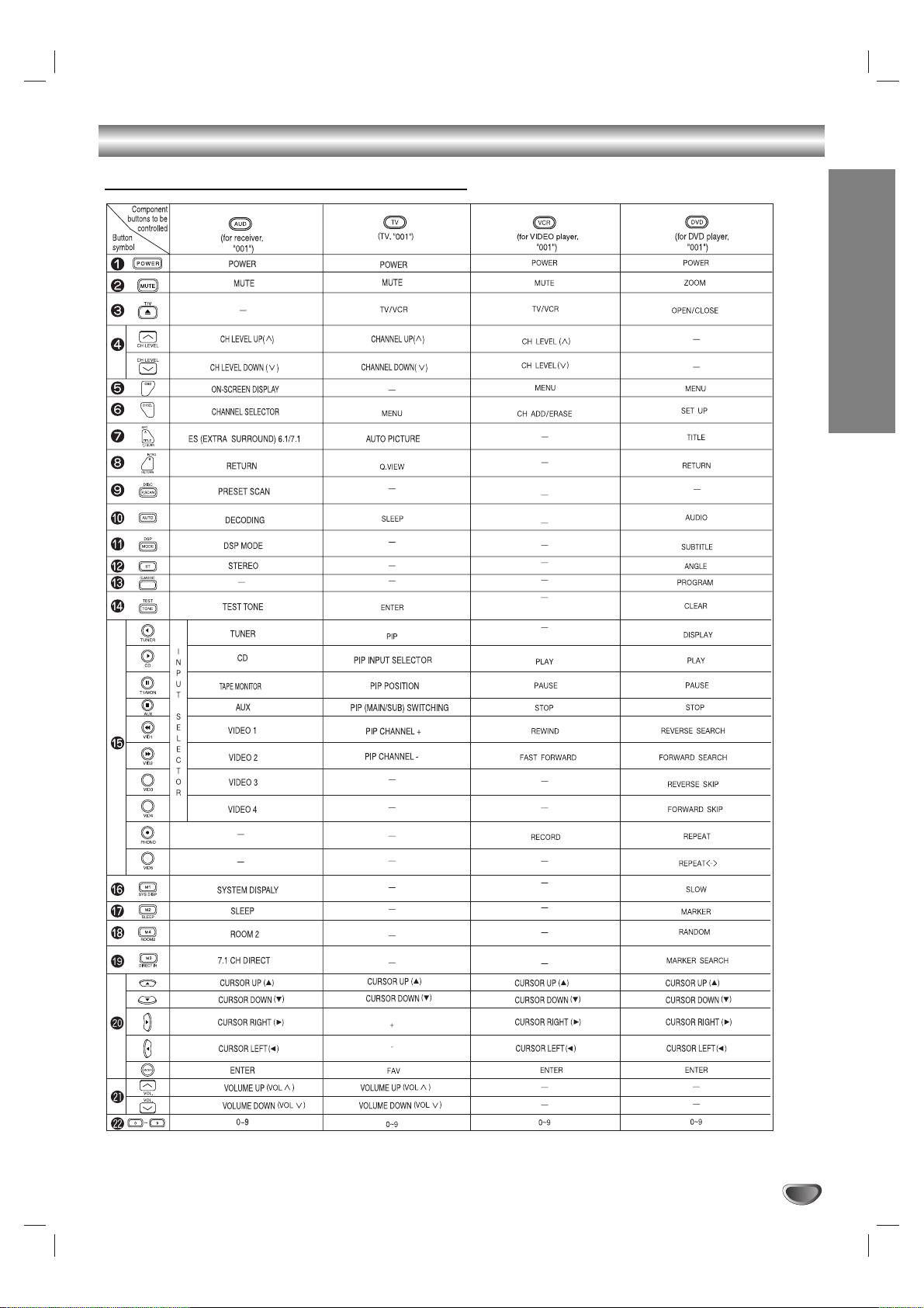
Function Table of the Numbered Buttons
xx
Notes:
l
Some functions for CD player, tape deck, etc. may not be available.
l
For details about functions, refer to the operating instructions of each component.

Universal Remote Controls
Operating Components with Remote
Control
1
Enter the setup code of the components
respectively, referring to “Entering a Setup
Code” (page13).
2
Turn on the components you want to operate.
3
Press the DEVICE button on the remote control
corresponding to the component you want to
operate.
4
Press the button corresponding to the operation
you want while aiming the remote control at the
REMOTE SENSOR on the component.
l
When a button is pressed, the corresponding
DEVICE button flickers.
Loading Batteries
1
Remove the cover.
2
Load four batteries(“AAA” size, 1.5 V) matching
the polarity.
Remote Control Operation Range
l
Use the remote control within a range of about 7
meters (23 feet) and angles of up to 30 degrees
aiming at the remote sensor.
12
DVD
VOL.
CH LEVEL
OSD
CH SEL
DSP
MODE
AUTO
ST
CENTER
MODE
TEST
TONE
DISC
P.SCAN
TUNER
CD
T1/MON AUX
PHONO
VID1 VID2 VID3 VID4 VID5
SYS DISP SLEEP
DIRECT IN
ROOM2
INTRO
RETURN
B
RPT
A
7.1 SURR
TITLE
ENTER
CHANNEL
SELECTOR
TONE MODE
ON/OFF
PHONES
SPEAKER
TUNING/PRESET
TEST TONE VIDEO LABEL
ROOM2 FEED
MULTI CONTROL
DYNAMIC
RANGE
T/P MODE
MASTER VOLUME
STANDBY
POWER
BAND CINEMA EQ
MEMO/ENTER
ON / OFF
S-VIDEOOPTICAL 3 IN VIDEO L - AUDIO - R
INPUT SELECTOR
AUDIO VIDEO DIGITAL/ANALOGEXTRA SURR. STEREO
SOURCE
DIRECT
TAPE MON. 7.1CH DIRECT DECODING
SURROUND MODE
VIDEO 4
INTRODUCTION
13
Universal Remote Controls
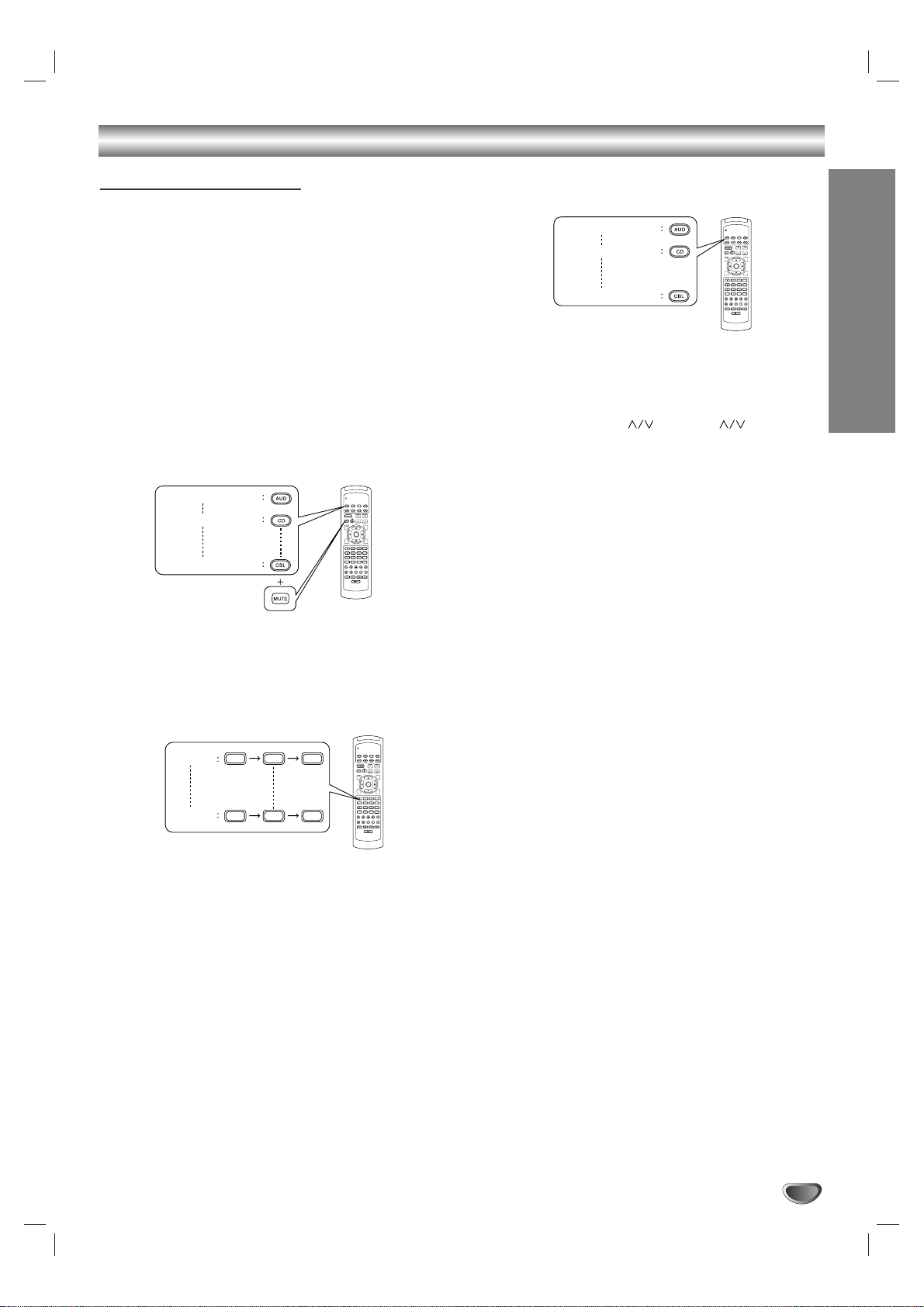
Entering a Setup Code
ll
This remote control can control up to eight different
components.
ll
Before operating audio and video components using
the remote control supplied with this receiver, the
setup code for each component should be entered.
1
Turn on the component you want to control.
Example) When entering the setup code for this
receiver, turn on this receiver.
2
Find the setup code for your component referring to “Set-Up Code Table” in the operating
manual of this remote control.
Example) The correct setup code for this receiver is
“001”.
3
Press the corresponding DEVICE and the MUTE
buttons simultaneously.
ll
Then the LED lamp and the corresponding
DEVICE button on the remote control light up for
20 seconds.
4
Enter the 3 digit setup code aiming the remote
control at the REMOTE SENSOR on the
component.
ll
Your component will be turned off when the
correct setup code is entered.
ll
Continue to enter the corresponding codes until
your component turns off.
ll
If the LED lamp and the corresponding DEVICE
button go off, start from the step again.
5
Press the corresponding DEVICE button to
store the setup code.
ll
Then the LED lamp and the corresponding
DEVICE button will flicker twice.
6
Operate the component using the corresponding
function buttons on the remote control such as
POWER, CH LEVEL and VOL buttons,
etc.
ll
If any of the buttons do not perform as they
should start from step
1 again to enter the next
setup code.
xx
Notes:
l
Some audio and video components have separate
buttons for POWER ON/OFF.
l
In this case, press the corresponding DEVICE button
to turn the component ON and press the POWER
button to turn the component OFF.
7
Repeat the above steps 1to 6for each of your
other components.
For receiver or amplifier
For CD player
For CABLE
OSD
ENTER
RPT
A
TITLE
7.1 SURR
DISC
P.SCAN
TUNER
CD
T1/MON AUX
VID1 VID2 VID3 VID4 VID5
SYS DISP SLEEP
DVD
VOL.
CH LEVEL
CH SEL
INTRO
B
RETURN
AUTO
DSP
MODE
ST
CENTER
TEST
MODE
TONE
PHONO
DIRECT IN
ROOM2
For receiver or amplifier
For CD player
For CABLE
OSD
ENTER
RPT
A
TITLE
7.1 SURR
DISC
P.SCAN
TUNER
CD
T1/MON AUX
VID1 VID2 VID3 VID4 VID5
SYS DISP SLEEP
DVD
VOL.
CH LEVEL
CH SEL
INTRO
B
RETURN
AUTO
DSP
MODE
ST
CENTER
TEST
MODE
TONE
PHONO
DIRECT IN
ROOM2
OSD
RPT
A
TITLE
7.1 SURR
DISC
P.SCAN
TUNER
CD
T1/MON AUX
VID1 VID2 VID3 VID4 VID5
SYS DISP SLEEP
DVD
VOL.
ENTER
TEST
TONE
DIRECT IN
For "001"
For "102"
001
102
CH LEVEL
CH SEL
INTRO
B
RETURN
AUTO
DSP
MODE
ST
CENTER
MODE
PHONO
ROOM2
14
Listening to a Program
xx
Notes:
ll
Before operating this receiver with the supplied
remote control, refer to “Universal Remote Controls”
on page 10 for details about operation.
ll
Before operating this receiver, first set this unit as
desired for optimum performance, doing the OSD
menu setting procedures. (For details, refer to “OSD
Menu Settings” on page 30.)
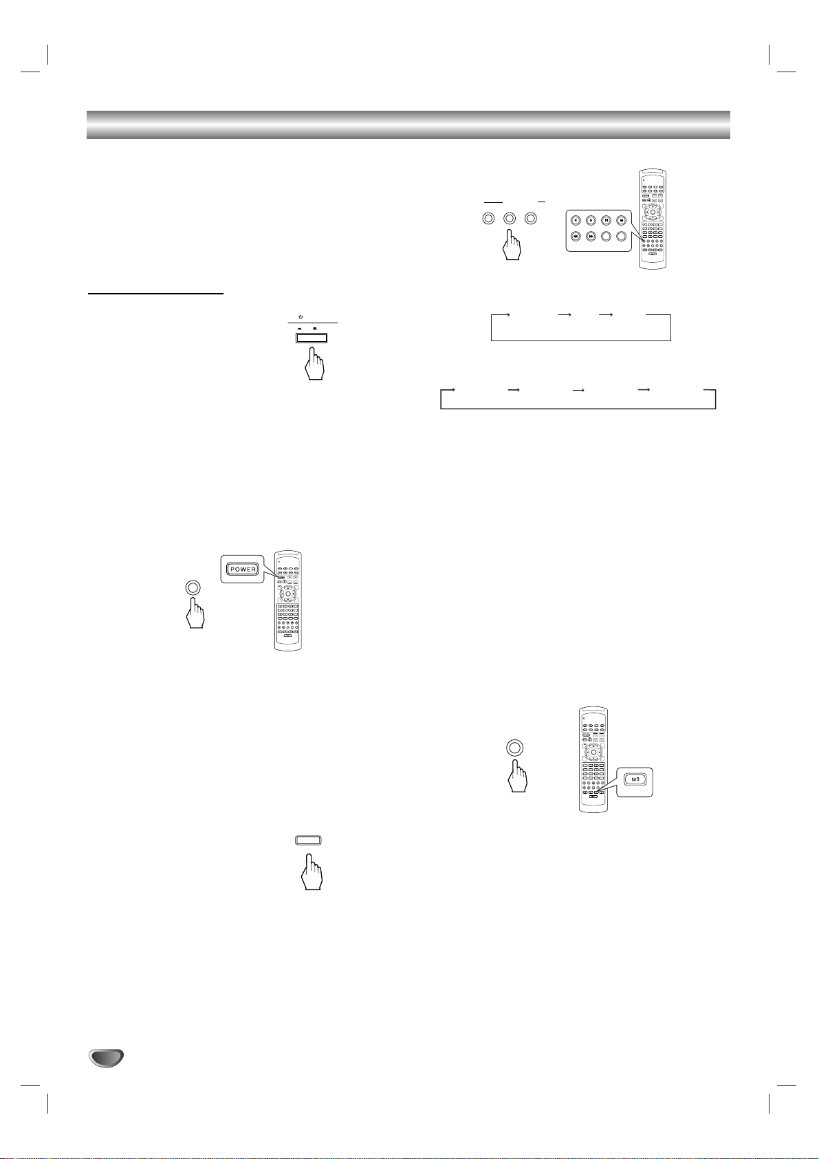
Before Operation
ll
Enter the standby mode.
ll
The STANDBY button lights up in red.
This means that the receiver is not disconnected
from the AC mains and a small amount of current is
retained to support the memorized contents and
operation readiness.
ll
To switch the power off, push the POWER switch
again.
ll
Then power is cut off and the STANDBY button goes
off.
1
In the standby mode, turn the power on.
ll
Each time the STANDBY button on the front
panel or the POWER button on the remote control is pressed, the receiver is turned on to enter
the operating mode(the STANDBY button lights
up in blue) or off to enter the standby mode (the
STANDBY button lights up in red).
ll
In the standby mode, if one of the INPUT SELECTOR buttons is pressed, the receiver is turned on
automatically and the desired input is selected.
2
Switch the speakers on.
ll
Then the SPEAKER indicator lights up on the
display and the sound can be heard from the
speakers connected to the speaker terminals.
ll
When using the headphones for private listening,
press the SPEAKER button again to switch the
speakers off.
3
Select the desired input source.
ll
Each time the “AUDIO” button is pressed, the
input source changes as follows:
ll
Each time the “VIDEO” button is pressed, the
input source changes as follows:
ll
When the TAPE MONITOR button is set to on so
that “TAPE MON” lights up, other inputs can not
be heard from the speakers.
To listen to an input source except TAPE MONITOR, be sure to set the TAPE MONITOR button
to off.
TAPE MONITOR function
You can connect either a tape deck or a graphic
equalizer to the receiver’s TAPE MONITOR jacks.
Only when you listen to the component connected
to these jacks, set the TAPE MONITOR button to
on.
If you connect a 3-head tape deck, you can listen to
the sound being recorded during recording, not the
source sound.
For further details, refer to the operating instructions of the component connected.
When selecting the 7.1 CH DIRECT as desired
ll
According to the surround back speaker setting.
“7.1(,6.1 or 5.1) CH DIRECT” is displayed and
the 8(/7/6) separate analog signals from 7.1 CH
decoder connected to this unit pass through the
tone(bass, treble) and volume circuits only and
directly transfer to the speakers.(In case that the
TAPE MONITOR button is set to on, the TAPE
MONITOR button is automatically set to off.)
ll
Press the 7.1 CH DIRECT button or select the
desired input source to cancel the 7.1 CH direct
function.
ll
These 8(/7/6) separate analog signals can be
heard only, not recorded.
POWER
ON / OFF
DVD
VOL.
CH LEVEL
OSD
CH SEL
DSP
MODE
AUTO
ST
CENTER
MODE
TEST
TONE
DISC
P.SCAN
TUNER
CD
T1/MON AUX
PHONO
VID1 VID2 VID3 VID4 VID5
SYS DISP SLEEP
DIRECT IN
ROOM2
INTRO
RETURN
B
RPT
A
7.1 SURR
TITLE
ENTER
STANDBY
or
ON/OFF
SPEAKER
DVD
VOL.
CH LEVEL
OSD
CH SEL
DSP
MODE
AUTO
ST
CENTER
MODE
TEST
TONE
DISC
P.SCAN
TUNER
CD
T1/MON AUX
PHONO
VID1 VID2 VID3 VID4 VID5
SYS DISP SLEEP
DIRECT IN
ROOM2
INTRO
RETURN
B
RPT
A
7.1 SURR
TITLE
ENTER
INPUT SELECTOR
AUDIO VIDEO
TAPE MON.
TUNER
CD
T1/MON AUX
VID1
VID2 VID3 VID4
or
TUNER CD AUX
(frequency display)
VIDEO 1 VIDEO 2 VIDEO 3 VIDEO 4
DVD
VOL.
CH LEVEL
OSD
CH SEL
DSP
MODE
AUTO
ST
CENTER
MODE
TEST
TONE
DISC
P.SCAN
TUNER
CD
T1/MON AUX
PHONO
VID1 VID2 VID3 VID4 VID5
SYS DISP SLEEP
DIRECT IN
ROOM2
INTRO
RETURN
B
RPT
A
7.1 SURR
TITLE
ENTER
7.1CH DIRECT
DIRECT IN
or
 Loading...