

Page 1
INDOOR UNIT
MULTI
F
MAX
MULTI
F
ENGINEERING MANUAL
Vertical-Horizontal
Air Handling Units
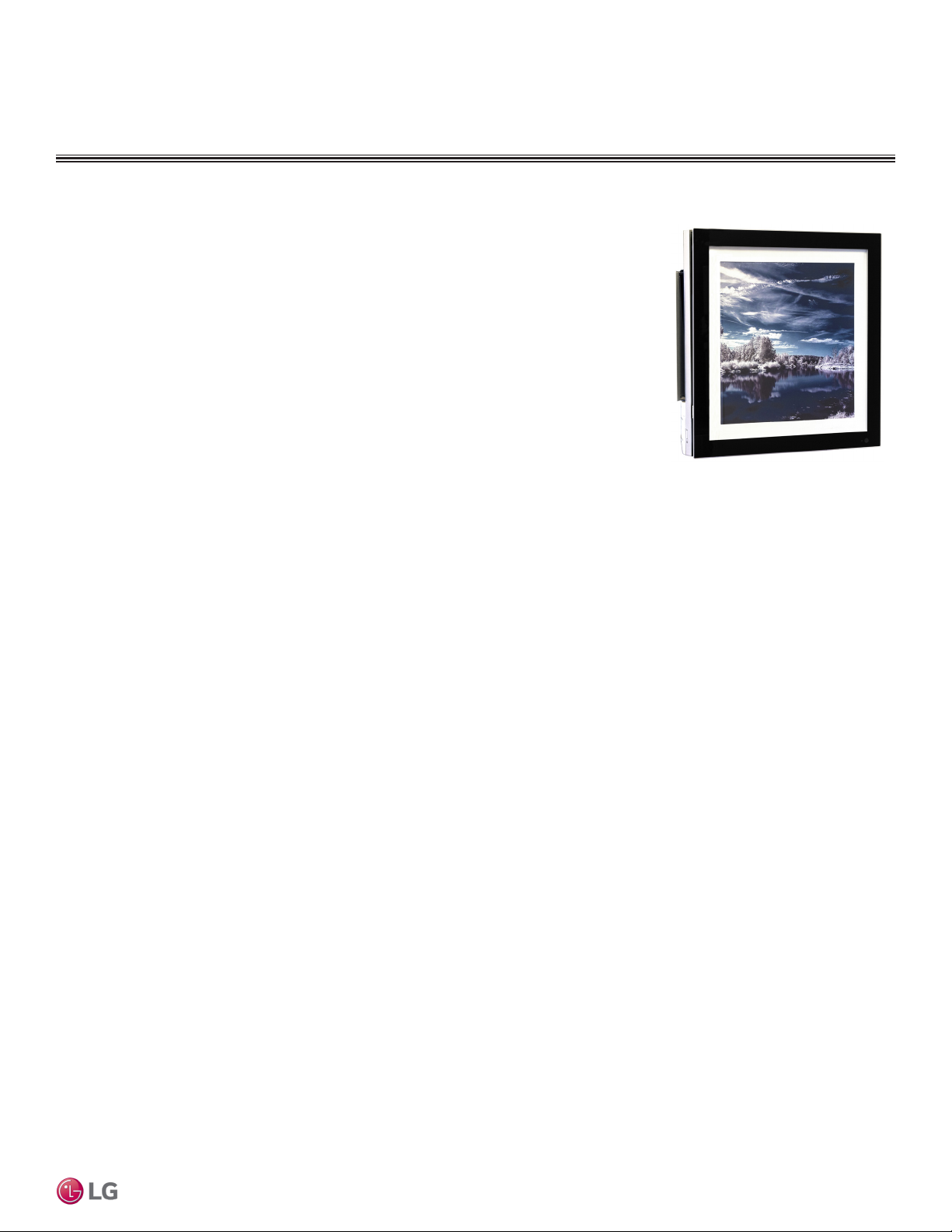
Art CoolTM Mirror
Wall-Mounted
Four-Way Ceiling Cassette
Indoor Units for Multi-Zone Heat Pump Systems
7,000 to 36,000 Btu/h
Ceiling-Concealed Duct
Art CoolTM Gallery
Wall-Mounted
Page 2
PROPRIETARY DATA NOTICE
DANGER
WARNING
CAUTION
This document, as well as all reports, illustrations, data, information, and
other materials are the property of LG Electronics U.S.A., Inc., and are
disclosed by LG Electronics U.S.A., Inc., only in confidence.
This document is for design purposes only.
EM_MultiF_IDU_3_18
For continual product development, LG reserves the right to change specifications without notice.
©LG Electronics Inc.
TABLE OF SYMBOLS
This document, as well as all reports, illustrations, data, information, and other materials are the property of LG Electronics U.S.A., Inc.
Note:
This symbol indicates an imminently hazardous situation which, if not avoided, will result in death or
serious injury.
This symbol indicates a potentially hazardous situation which, if not avoided, could result in death or
serious injury.
This symbol indicates a potentially hazardous situation which, if not avoided, may result in minor or
moderate injury.
This symbol indicates situations that may result in equipment or property damage accidents only.
This symbol indicates an action that should not be performed.
Page 3

MULTI
MAX
MULTI
F
TABLE OF CONTENTS
Convergence of Technology,
Innovation, Flexibility, & Style ....................................................4
Unit Nomenclature .......................................................................5
Functions, Controls and
Options Overview ........................................................................6
Art Cool Mirror Indoor Units .....................................................10
Mechanical Specications and Features ........................................... 10
General Data / Specications .............................................................11
Dimensions ........................................................................................ 12
Cooling Capacity Table ...................................................................... 14
Heating Capacity Table ...................................................................... 16
Acoustic Data .................................................................................... 17
Air Velocity and Temperature Distribution .......................................... 18
Refrigerant Flow Diagram .................................................................. 19
Wiring Diagram .................................................................................. 20
Factory Supplied Parts and Materials ................................................ 21
Installation and Best Layout Practices ............................................... 22
Art Cool Gallery Indoor Units ...................................................29
Mechanical Specications and Features ........................................... 29
General Data / Specications ............................................................ 30
Dimensions ........................................................................................ 31
Cooling Capacity Table ...................................................................... 32
Heating Capacity Table ...................................................................... 33
Acoustic Data .................................................................................... 34
Air Velocity and Temperature Distribution .......................................... 35
Refrigerant Flow Diagram .................................................................. 36
Wiring Diagram .................................................................................. 37
Factory Supplied Parts and Materials ................................................ 38
Installation and Best Layout Practices ............................................... 39
Standard Wall-Mounted Indoor Units ......................................49
Mechanical Specications and Features ........................................... 49
General Data / Specications ............................................................ 50
Dimensions ........................................................................................ 51
Cooling Capacity Table ...................................................................... 53
Heating Capacity Table ...................................................................... 56
Acoustic Data .................................................................................... 58
Air Velocity and Temperature Distribution .......................................... 60
Refrigerant Flow Diagram .................................................................. 62
Wiring Diagram .................................................................................. 63
Factory Supplied Parts and Materials ................................................ 65
Installation and Best Layout Practices ............................................... 66
Duct (Low Static) Indoor Units .................................................73
Mechanical Specications and Features ........................................... 73
General Data / Specications ............................................................ 74
Dimensions ........................................................................................ 75
Cooling Capacity Table ...................................................................... 76
Heating Capacity Table ...................................................................... 78
External Static Pressure .................................................................... 79
Acoustic Data .................................................................................... 80
Refrigerant Flow Diagrams ................................................................ 81
Wiring Diagram .................................................................................. 83
Factory Supplied Parts and Materials ................................................ 84
Installation and Best Layout Practices ............................................... 85
Duct (High Static) Indoor Units ................................................95
Mechanical Specications and Features ........................................... 95
General Data / Specications ............................................................ 96
Dimensions ........................................................................................ 97
Cooling Capacity Table ...................................................................... 98
Heating Capacity Table ...................................................................... 99
External Static Pressure / Acoustic Data ......................................... 100
Refrigerant Flow Diagrams .............................................................. 101
Wiring Diagrams .............................................................................. 102
Factory Supplied Parts and Materials / Installation ......................... 103
Installation and Best Layout Practices ............................................. 104
Four-Way Ceiling Cassette Indoor Units ...............................113
Mechanical Specications and Features ..........................................113
General Data / Specications ...........................................................114
Dimensions .......................................................................................115
Cooling Capacity Table ..................................................................... 117
Heating Capacity Table .................................................................... 120
Acoustic Data .................................................................................. 121
Air Velocity and Temperature Distribution ........................................ 123
Refrigerant Flow Diagram ................................................................ 125
Wiring Diagram ................................................................................ 126
Factory Supplied Parts and Materials .............................................. 127
Installation and Best Layout Practices ............................................. 128
Two-Way VAHU Indoor Units .................................................. 137
Mechanical Specications and Features ......................................... 137
General Data / Specications .......................................................... 138
Dimensions ...................................................................................... 139
Cooling Capacity Table .................................................................... 140
Heating Capacity Table .................................................................... 141
External Static Pressure .................................................................. 142
Acoustic Data .................................................................................. 143
Refrigerant Flow Diagram ................................................................ 144
Wiring Diagram ................................................................................ 145
Factory Supplied Parts and Materials .............................................. 147
Installation and Best Layout Practices ............................................. 148
Four-Way VAHU Indoor Units ................................................. 157
Mechanical Specications and Features ......................................... 157
General Data / Specications .......................................................... 158
Dimensions ...................................................................................... 159
Cooling Capacity Table .................................................................... 160
Heating Capacity Table .................................................................... 162
External Static Pressure and Airow Ranges .................................. 164
Acoustic Data .................................................................................. 167
Refrigerant Flow Diagram ................................................................ 170
Wiring Diagram ................................................................................ 171
Factory Supplied Parts and Materials .............................................. 173
Installation and Best Layout Practices ............................................. 174
Application Guidelines ............................................................183
Equipment Selection Procedure ...................................................... 184
Placement Considerations ............................................................... 191
Refrigerant Piping Design ......................................................198
Design Guideline Summary ............................................................. 198
Creating a Balanced System / Manual Layout Procedure 200
Condensate Drain Piping ................................................................. 201
Electrical Connections ............................................................204
General Information ......................................................................... 204
Power Wiring (208-230V) and Comm Cable Details ....................... 207
Remote Controller Connections ...................................................... 212
Indoor Unit Group Control ............................................................... 213
Acronyms .................................................................................214
Introduction
INTRODUCTION | 3
Page 4
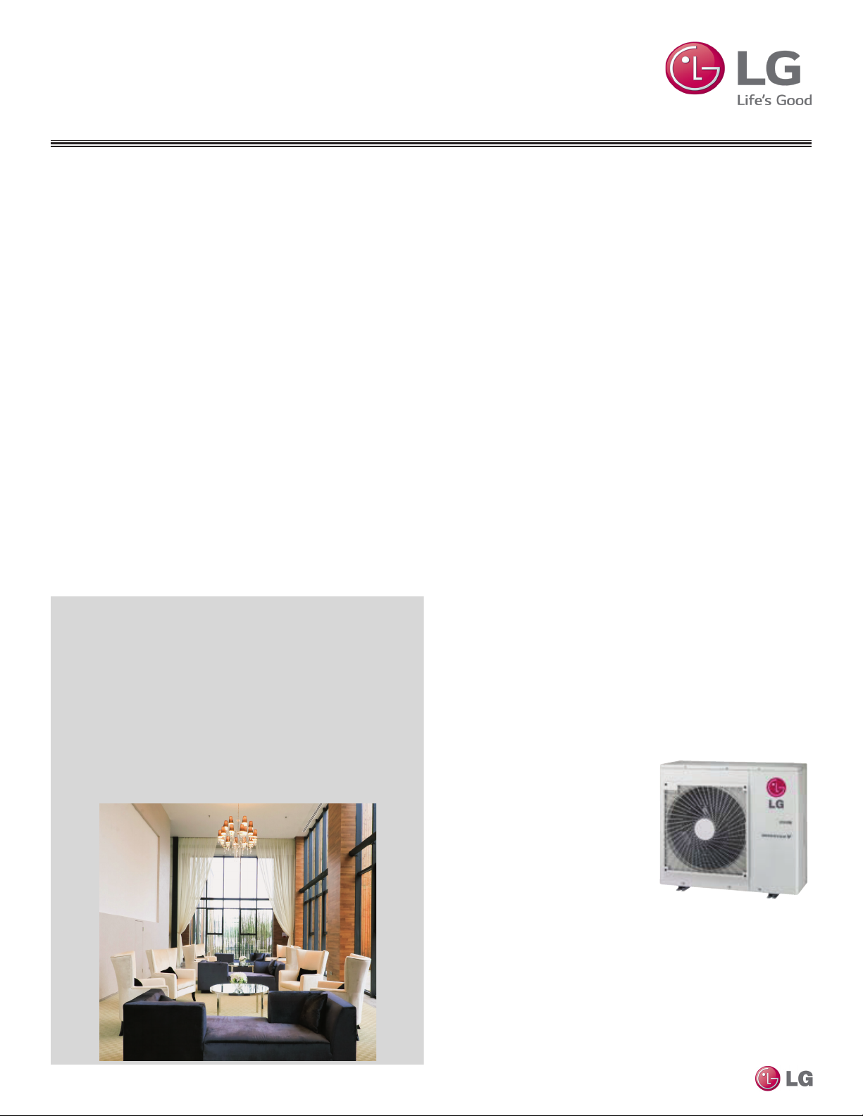
CONVERGENCE OF TECHNOLOGY,
MULTI
F
INNOVATION, FLEXIBILITY, & STYLE
About LG Electronics, Inc.
LG Electronics is a global leader and technology innovator in consumer electronics, mobile communications, and home appliances.
LG Electronics comprises five business units—Home Entertainment,
Mobile Communications, Air Conditioning, Business Solutions, and
Home Appliance. LG is one of the world’s leading producers of flat
panel televisions, audio and video products, mobile handsets, air
conditioners, and washing machines. LG’s commercial air conditioning business unit was established in 1968 and has built its lineup of
residential and commercial products to include VRF, Multi F, ductfree split systems, packaged terminal air conditioners (PTACs), and
room air conditioners. In 2011, the air conditioning and energy solutions business unit grew to include LED lighting and solar products.
For more information, visit www.lg.com.
Multi-Zone Systems
LG HVAC systems offer a range of solutions that are cost efficient,
quiet and attractive. Multi-zone systems are “split” into indoor and
outdoor units, and provide a smart alternative to both central HVAC
and window-mounted air conditioners. These inverter heat pump systems are available in a variety of configurations to suit different cooling and heating situations. Installation by a trained HVAC contractor
is safe and easy – little to no duct work or sheet metal is required.
Multi F Systems
LG’s inverter heat pumps can support two, three, or four indoor
units that are typically installed in separate rooms. Each indoor unit
Benefits of Multi F Systems
• Individual zone control
• Long refrigerant piping lengths
• High refrigerant piping elevation differences
• Maximum flexibility
• Operating ranges of 14°F to 118°F (DB) in cooling and -4°F to
75°F (DB) in heating if connected to standard Multi F Outdoor Units
or -13°F to 75°F (DB) in heating if connected to Multi F with LG
REDº Outdoor Units.
• Quiet and comfortable environment
Multi F and Multi F MAX Indoor Unit Engineering Manual
• Reduced ductwork
includes its own remote control, allowing the customer to set the
temperature individually. Indoor units are available in several differ-
ent congurations: Art Cool™ Mirror wall-mounted, Art Cool Gallery
wall-mounted, standard wall-mounted, four-way ceiling cassettes,
ceiling-concealed duct (high and low static), and vertical-horizontal air
handling models. Multi F MAX systems can operate up to eight indoor
units through two-, three-, or four-port branch distribution units.
Adaptable and Flexible
Multi F outdoor units can be adapted to a wide range of building ap-
plications and sizes such as schools, hotels, hospitals, ofces, and
residences. The system components are lightweight and compact so
they can be placed in buildings without expensive cranes, they easily
fit into most service elevators, and they can be set in place with
minimal structural reinforcements requirements.
Multi F technology allows you to pipe farther by reaching areas of the
building that would require the installation of a second system when
using traditional direct-expansion cooling and heating equipment. Multi
F provides the designer with uncompromised pipe system engineering
exibility—long pipe runs and large elevation differences. Whether your
building is a condominium, a hotel, a school, or an ofce complex, Multi
F is best suited to reach the farthest corners and elevations.
Smaller Chases and Plenums
LG Multi F systems use refrigerant piping to move heat, resulting in
smaller space requirements for piping as compared to chilled water
or roof top systems. This helps reduce the overall construction and
material cost of the building, and gives back leasable space. Flexible
and logical placement of system components, reduced back-andforth pipe lengths, and fewer joints lowers installation costs and
minimizes potential leaking.
Quality Commitment
LG is committed to the success of duct-free projects. We provide
technical support during installation and commissioning. LG offers
a variety of classes designed for installers and servicers on Multi F
installation. Classes are conducted at LG’s training centers
and in field locations at various
times throughout the year and on
special request.
4 | INTRODUCTION
Due to our policy of continuous product innovation, some specications may change without notication.
©LG Electronics U.S.A., Inc., Englewood Cliffs, NJ. All rights reserved. “LG” is a registered trademark of LG Corp.
Page 5
MULTI
F
MAX
MULTI
F
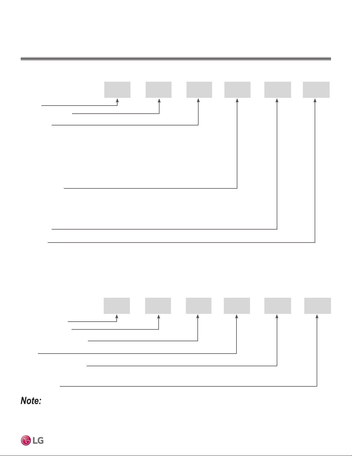
UNIT NOMENCLATURE
Multi-Zone Systems — Indoor Units and Outdoor Units
L
L = LG
Type: M = Multi-Zone
Component:
AN: Art Cool™ Wall-Mounted Indoor Unit
N: Standard Wall-Mounted Indoor Unit
CN: Four-Way Ceiling-Cassette Indoor Unit
DN: Ceiling-Concealed Duct (Low Static) Indoor Unit
HN: Ceiling-Concealed Duct (High Static) Indoor Unit
VN: Vertical-Horizontal Air Handling Indoor Unit
U: Outdoor Unit
Nominal Capacity
(Nominal cooling capacity in Btu/h):
07 = 7,000
09 = 9,000
12 = 12,000
Generation
Features:
H = Heat Pump
V = Inverter
T = High Wall-Mounted Indoor Unit
P = Art Cool Gallery Indoor Unit
15 = 15,000
18 = 18,000
24 = 24,000
30 = 30,000
36 = 36,000
42 = 42,000
M
48 = 48,000
54 = 54,000
DN 12 6 HV
Introduction
Branch Distribution Units
P = Part (Accessory)
Type: M = Multi-Zone
BD: Branch Distribution Unit
Family
Number of Port Connections
(Maximum Number of Connectable Indoor Units): 2, 3, 4
• Voltage for all equipment is 208-230V, 60 Hz, 1-phase.
• All indoor units are compatible with wired controllers.
• All outdoor units are LGAP control network compatible with PI-485 V-net Control Integration Board (PMNFP14A1, sold separately).
• Compatible single zone IDU nomenclature is listed in the Single Zone Wall-Mounted IDU Engineering Manual.
Generation: 0, 1
P
Due to our policy of continuous product innovation, some specications may change without notication.
©LG Electronics U.S.A., Inc., Englewood Cliffs, NJ. All rights reserved. “LG” is a registered trademark of LG Corp.
M
BD 36
02
INTRODUCTION | 5
Page 6
MULTI
F
MAX
MULTI
F
FUNCTIONS, CONTROLS AND
OPTIONS OVERVIEW
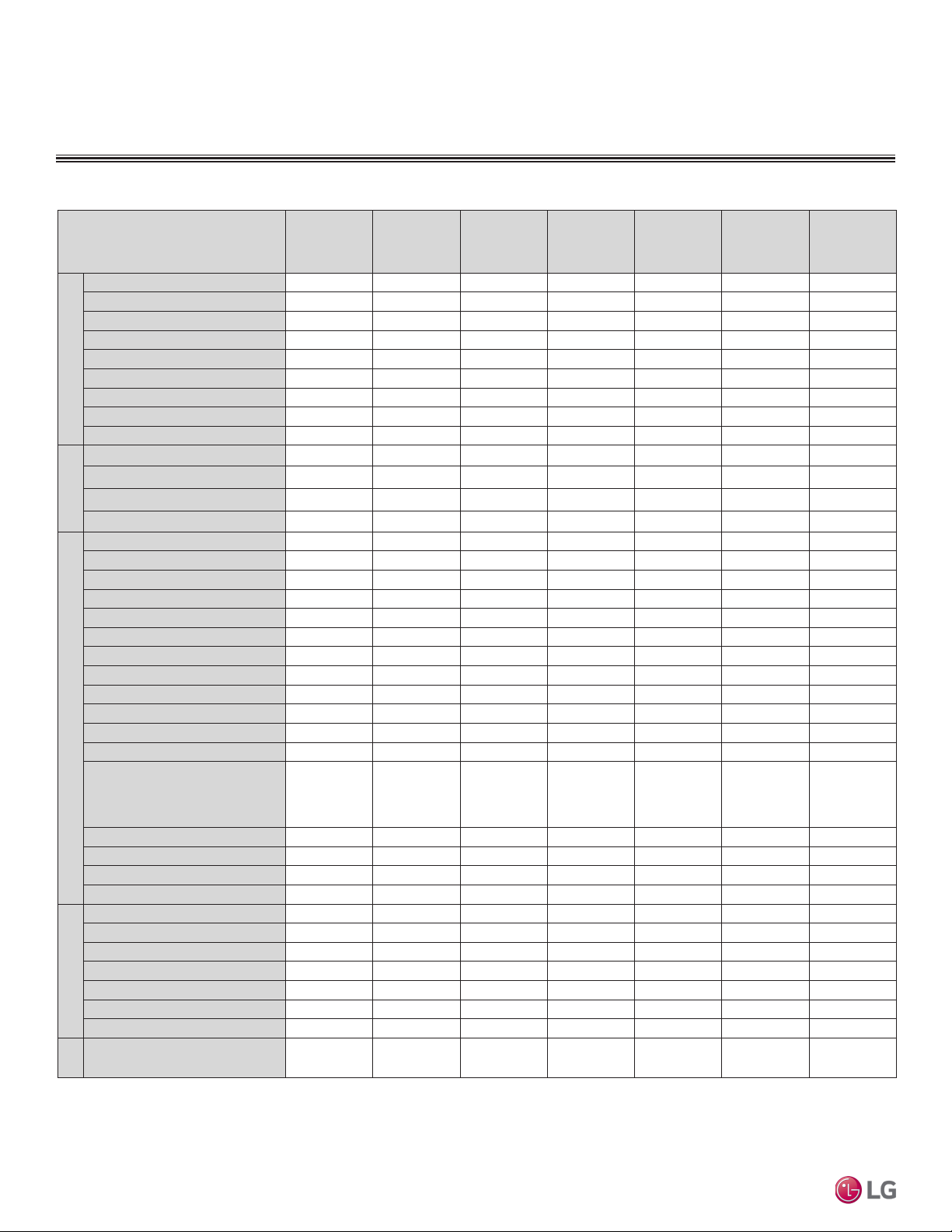
Table 1: Indoor Units—Functions, Controls and Options.
ART COOL™
Indoor Unit Type
Mirror Wall
Mounted
Air supply outlets
Airflow direction (left/right)
Airflow direction (up/down)
Auto swing (left/right)
Auto swing (up/down)
Airow
Airflow steps (fan/cool/heat)
Comfort Air (random fan speed)
Jet-cool/Jet Heat (power wind)
1 3 1 1 2 4 1
Auto Auto Auto
Auto Auto Auto Auto
√ √ √
√ √ √ √
6 / 6 / 6 5 / 5 / 4 6 / 6 / 6 3 / 3 / 3 3 / 3 / 3 4 / 5 / 4 3 / 3 / 3
√ √ √ √
√ √ √ √
Swirl wind
Washable anti-fungal
2
Plasma
Filter
3M Micro Dust Filter
1
2
√ √ √ √ √ √
√ √
Ventilation
Drain pump
E.S.P. control
Electric heater
High ceiling
Hot Start
Self diagnostics
Soft Dry (dehumidification)
Auto operation
Auto clean (coil dry)
Auto restart
Child lock
Operation
Forced operation
5
√ √ √ √ √ √ √
√ √ √ √ √ √ √
√ √ √ √ √ √ √
√ √ √ √ √ √ √
√ √ √
√ √ √ √ √ √
o o o o o o o
√ √ √ √
Group control – Requires the use
of one Group control Cable Kit
(PZCWRCG3) for every
o o o o o o o
additional indoor unit
Sleep mode
Timer (on/off)
Multi F and Multi F MAX Indoor Unit Engineering Manual
Weekly schedule
Two thermistor control
7-Day programmable controller
Simple wired remote controller
Wireless LCD remote control
Dry contact
Dry contact (temperature setting)
Controllers
Central control (LGAP)
Connector for Water Sensor
8
Wi-Fi
Special
Function
√ √ √ √ √ √ √
√ √ √ √ √ √ √
o o o √ √ o √
o o o o o o o
o o o o o o o
o o o √ √ o √
√ √ √ o
o o o o o o √
o o o o o o o
√ √ √ √ √ √ √
√ √ √
√ √ o
ART COOL™
Gallery
Standard Wall
Mounted
Concealed
(Low Static)
Ceiling
Ducted
Ceiling
Concealed
(High Static)
Ducted
Four-Way
Ceiling
Cassette
√
3
o
4
√
√ √ √
√ √ √
√
6
6
o
√ o
VerticalHorizontal Air
Handling Unit
o
5
6
7
1
2
3
Plasma kit.
4
limitations apply).
6 | INTRODUCTION
Primary washable filters.
Secondary filter
Branch location and static pressure requirements. Requires PTPKQ0
Requires ventilation kit PTVK430 (Temperature, humidity, and volume
Due to our policy of continuous product innovation, some specications may change without notication.
©LG Electronics U.S.A., Inc., Englewood Cliffs, NJ. All rights reserved. “LG” is a registered trademark of LG Corp.
5
Group control may affect available features
6
Requires wired zone controller
7
For use with 3rd party thermostat
8
Embedded. Optional for LVNxxxHV4 4-way VAHU.
Not available for 2-way LMVNxxxHV VAHU.
√ = Standard feature
o = Unit option
Page 7
MULTI
F
MAX
MULTI
F
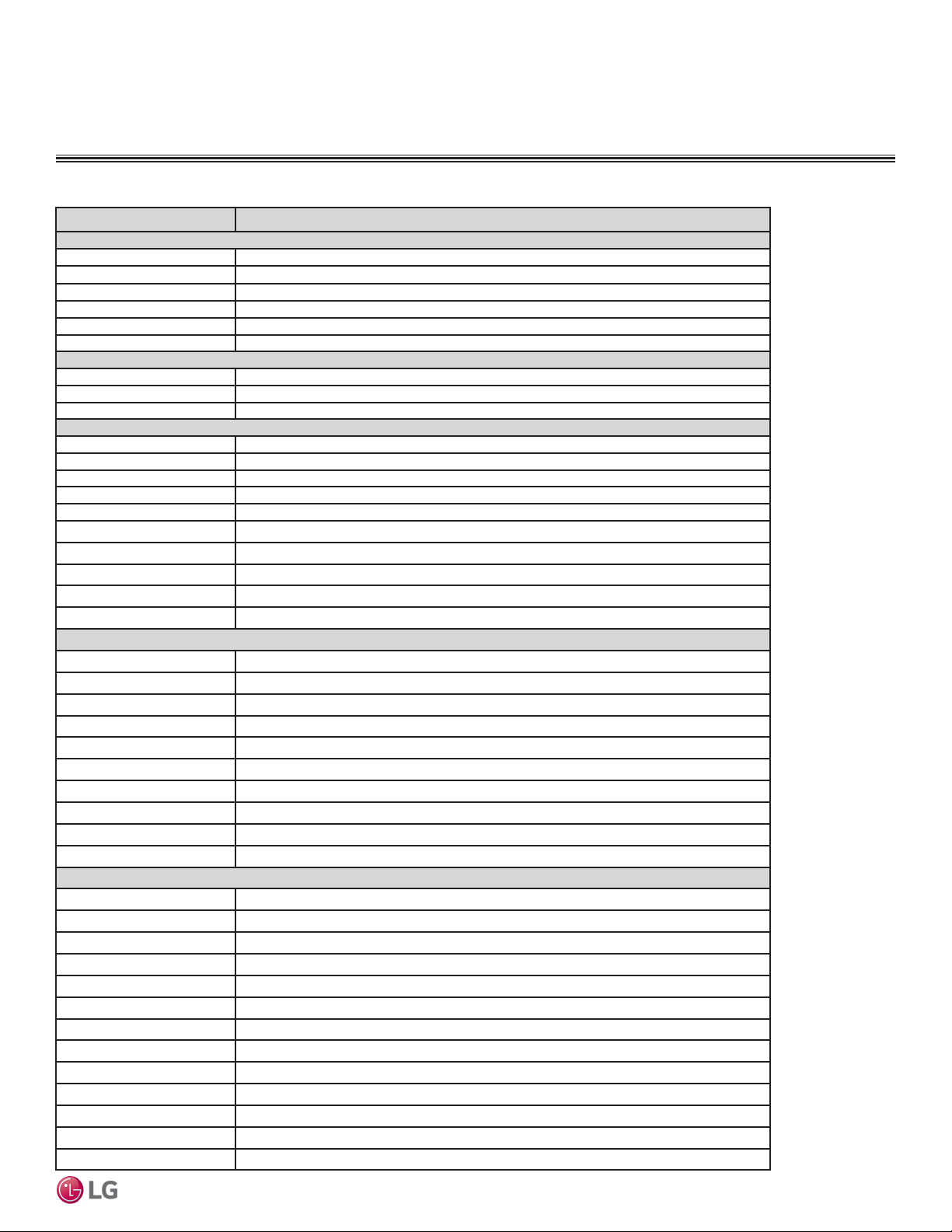
Table 2: Indoor Unit Accessories Overview.
FUNCTIONS, CONTROLS AND
Model No. Description
For Four-Way Ceiling-Cassette Indoor Units
PT-QCHW0 Ceiling Grille
PT-UQC Ceiling Grille
PTVK430 Flange for All Capacities
PTDCQ Decorative Cover
PTPKQ0 Plasma Filter
PRARH0 Aux Heat Relay Kit
Wall-Mounted Indoor Units
PCRCUDT3 Wi-Fi Module (LSN/LMN models)
AG-9300-LG Condensate Sensor
PRARS1 Aux Heat Relay Kit
For Vertical-Horizontal Air Handing Units
PNDFJ0 Downflow Conversion Kit (18/24MBH)
PNDFK0 Downflow Conversiion Kit (36MBH)
ANEH033B1 3 kW Electric Heater (18-36MBH)
ANEH053B1 5 kW Electric Heater (18-36MBH)
ANEH083B2 8 kW Electric Heater (18-36MBH)
ANEH103B2 10 kW Electric Heater (18-36MBH)
ANEH153B2 15 kW Electric Heater (36MBH)
ANEH203B2 20 kW Electric Heater (36MBH)
PRARH0 Aux Heat Relay Kit
PCRCUDT3 Wi-Fi Module
For Ceiling-Concealed Duct (High Static) Indoor Units
ZFBXBG01A High Efficiency Filter Box
ZFBXD201A Dynamic V8 2VL Low Profile Air Cleaner
ZPLMV201A Dynamic 2VL Air Cleaner Low Profile Return Air Plenum
ZFBXD402A Dynamic V8 4VL Low Profile Air Cleaner
ZPLMV402A Dynamic 4VL Air Cleaner Low Profile Return Air Plenum
ZFLT1301A 4-Pack Dynamic V8 VL Air Cleaner Replacement Filter Pads
ZFLT1302A 24-Pack Dynamic V8 VL Air Cleaner Replacement Filter Pads
ZGRLRA01A Dynamic V8 Air Cleaner Louvered Return Air Grille (one per plenum )
ZGRLRA02A Dynamic V8 Air Cleaner Egg Crate Return Air Grille (one per plenum)
PRARH0 Aux Heat Relay Kit
Controls Accessories
PQWRHQ0FDB Wireless Handheld Remote (Duct/VAHU)
PREMTA000A Premium Controller
PREMTB10U Programmable Controller
PQRCVCL0Q(W) Simple Controller (Wall/Cassette)
PREMTBVC0 MultiSITE CRC1 Base Controller
PREMTBVC1 MultiSITE CRC1 Plus Controller
ZVRCZ**** MultiSITE CRC1 Wireless Accessories
PDRYCB100 Dry Contact (Simple)
PDRYCB300 Dry Contact (3rd party controller)
PDRYCB400 Dry Contact (Setback)
ZRTBS01 Remote Temp Sensor (Cassette/Duct/VAHU)
PZCWRCG3 Group Control Cable Kit
PZCWRC1 Controller Extension Cable
Due to our policy of continuous product innovation, some specications may change without notication.
©LG Electronics U.S.A., Inc., Englewood Cliffs, NJ. All rights reserved. “LG” is a registered trademark of LG Corp.
OPTIONS OVERVIEW
Introduction
INTRODUCTION | 7
Page 8

Multi F and Multi F MAX Indoor Unit Engineering Manual
MULTI
F
MAX
MULTI
F
8 | INTRODUCTION
Due to our policy of continuous product innovation, some specications may change without notication.
©LG Electronics U.S.A., Inc., Englewood Cliffs, NJ. All rights reserved. “LG” is a registered trademark of LG Corp.
Page 9

™
ART COO
L
MIRROR
INDOOR UNIT DATA
“Mechanical Specifications” on page 10
“General Data / Specifications” on page 11
“Dimensions” on page 12
“Cooling Capacity Table” on page 14
“Heating Capacity Table” on page 16
“Acoustic Data” on page 17
“Air Velocity and Temperature Distribution” on page 18
“Refrigerant Flow Diagram” on page 19
“Wiring Diagram” on page 20
“Factory Supplied Parts and Materials” on page 21
“Installation and Best Layout Practices” on page 22
Page 10
ART COOL MIRROR INDOOR UNITS
MULTI
F
MAX
MULTI
F
Mechanical Specications and Features
ART COOL Mirror Wall-Mounted
Indoor Units
General
All LG indoor units are factory assembled, wired, piped, and provided with a control circuit board, fan, and motor. ART COOL Mirror
Wall-Mounted indoor units have a sound rating no higher than 44
dB(A) as tested per KSA0701 ISO Standard 3745.
Coil
Indoor unit coils are comprised of a minimum of two rows of
aluminum fins mechanically bonded to copper tubing. The coils are
pressure tested at the factory. Each unit is provided with a factory
installed condensate drain pan below the coil.
Refrigerant System
System is designed for use with R410A refrigerant. The refrigeration
circuit is pressure-tested at the factory and shipped with a holding
charge of helium gas. Refrigerant pipe connections are 45° flare.
All refrigerant lines from the outdoor unit to the indoor units must be
field insulated.
Electrical
Each indoor unit is designed to operate using 208–230/60/1 power
with voltage variances of ±10%.
Casing
Units are designed to mount on a vertical surface, and are shipped
with a separate back plate that secures the unit to the wall, protruding no more than nine (9) inches. Unit is designed so that refrigerant
piping can be installed in one (1) of four (4) different directions.
Finish
The Art Cool Mirror unit has a flat, architectural panel with a smoked
charcoal mirror finish. Unit casing has a dark grey finish and is
manufactured of heavy-duty acrylonitrile butadiene styrene (ABS)
and high impact polystyrene (HIPS) plastic.
Fan Assembly and Control
The unit has a single, direct-drive, crossow fan made of high strength
ABS plastic. The fan motor is brushless digitally controlled (BLDC)
with permanently lubricated and sealed ball bearings. The fan and
Multi F and Multi F MAX Indoor Unit Engineering Manual
motor assembly is mounted on vibration attenuating rubber grommets.
Fan speed is controlled using a microprocessor-based direct digitally
controlled algorithm that provides pre-programmed, eld-selectable
xed or auto fan speeds in the Heating and Cooling modes. For Art
Cool Mirror Wall-Mounted units, the indoor fan has Low, Med, High,
Jet Cool and Auto settings for Cooling mode; and has Low, Med, High,
Jet Heat and Auto settings for Heating mode. The Auto setting adjusts
the fan speed based on the difference between the controller setpoint
and space temperature. Also, the separate Chaos setting provides a
simultaneous and random change in fan speed and ow direction at
the discharge, simulating a natural outdoor breeze.
Air Filter
Return air inlet has a factory-supplied primary removable, washable
filter. The unit is also equipped with a secondary 3M Micro Dust
filter. Filters are accessed from the front of the unit without the use
of tools.
Airflow Guide Vanes
A motorized guide vane is factory installed, and allows the ability to
control the direction of airflow from side to side. A motorized louver
provides an automatic change in airflow by directing the air up and
down to provide uniform air distribution.
Microprocessor Control
The indoor unit is provided with an integrated control panel to communicate with the outdoor unit. All unit operation parameters are
stored in non-volatile memory resident on the unit microprocessor.
The microprocessor controls space temperature through using the
value provided by the temperature sensor within the indoor unit.
The microprocessor control will activate indoor unit operation when
the indoor room temperature falls below or rises above a setpoint
temperature, at which point, a signal is sent to the outdoor unit to
begin the appropriate mode. The microprocessor will also provide
self-diagnostics and auto restart functions. A field-supplied four-wire
power/communications cable must be installed to connect the indoor
unit(s) to the outdoor unit.
Controls
The indoor unit casing has a factory-standard, integral infrared
sensor designed to communicate with the supplied LG wireless
handheld remote controller. An optional LG supplied wired controller
is available as an additional accessory. Communication between the
indoor units and the outdoor unit is accomplished through 18 AWG,
four-core, stranded and shielded power/communication cable. The
indoor unit has built-in wi-fi and can be controlled with LG’s SmartThinQ app on a smart device. A field-supplied wi-fi network and
smart device are required. The SmartThinQ app is free and is available for Android and iOS smart devices.
Condensate
The unit is designed for gravity draining of condensate and includes
a flexible drain hose capable of installation in one of two directions.
Unit includes a connection that is compatible with the AquaGuard®
AG-9300-LG condensate sensor.
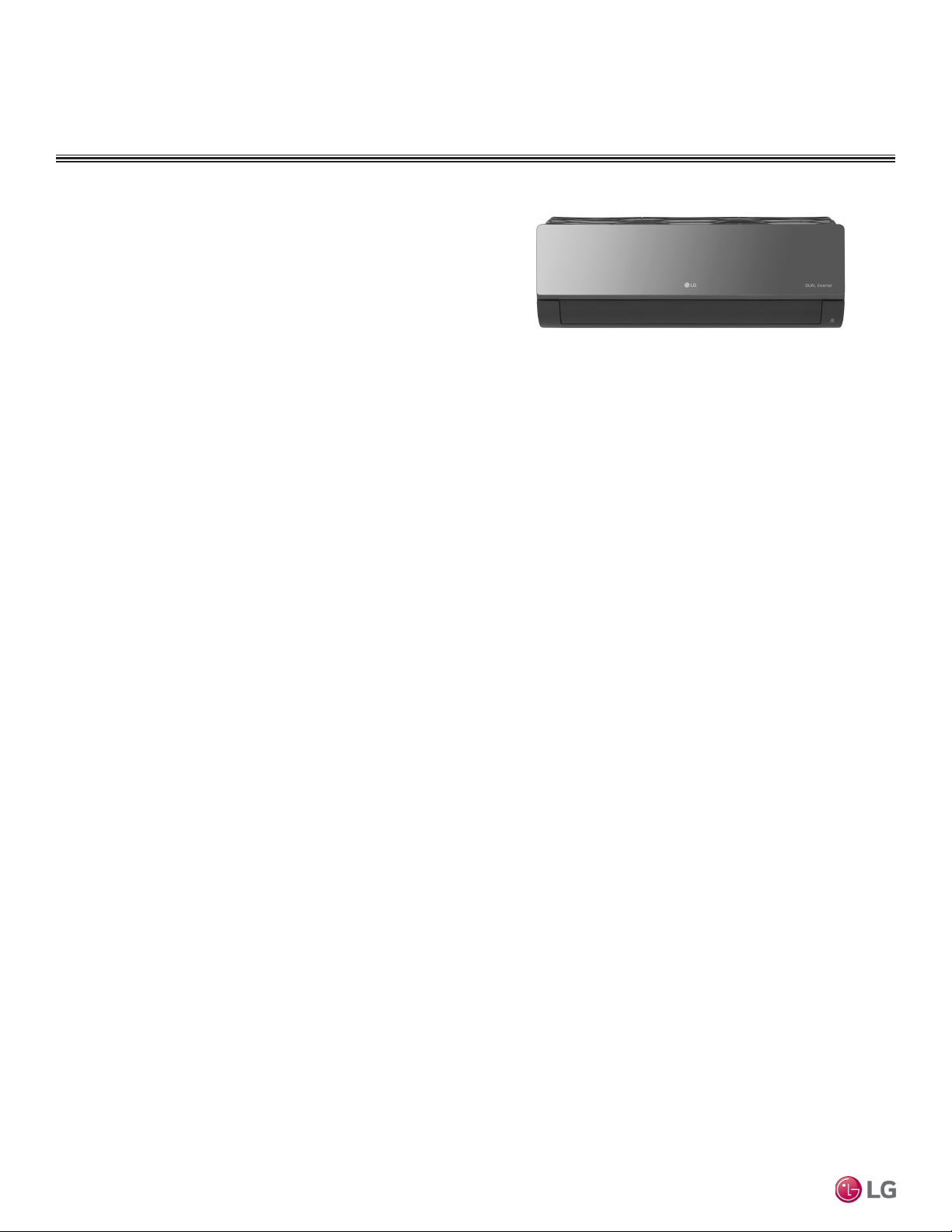
Features
• Inverter (Variable speed fan)
• Comfort Air
• 3M filter
• Jet cool/Jet heat
10 | ART COOL MIR ROR
©LG Electronics U.S.A., Inc., Englewood Cliffs, NJ. All rights reserved. “LG” is a registered trademark of LG Corp.
• Group Control
• Self-cleaning indoor coil
• Auto operation
• Auto restart operation
Due to our policy of continuous product innovation, some specications may change without notication.
Figure 1: Multi F Art Cool Mirror Wall-Mounted Indoor Unit.
• Built-in wi-fi
• Dehumidifying function
• Self diagnosis function
• Wireless LCD remote control included
Page 11
ART COOL MIRROR INDOOR UNITS
MULTI
F
MAX
MULTI
F
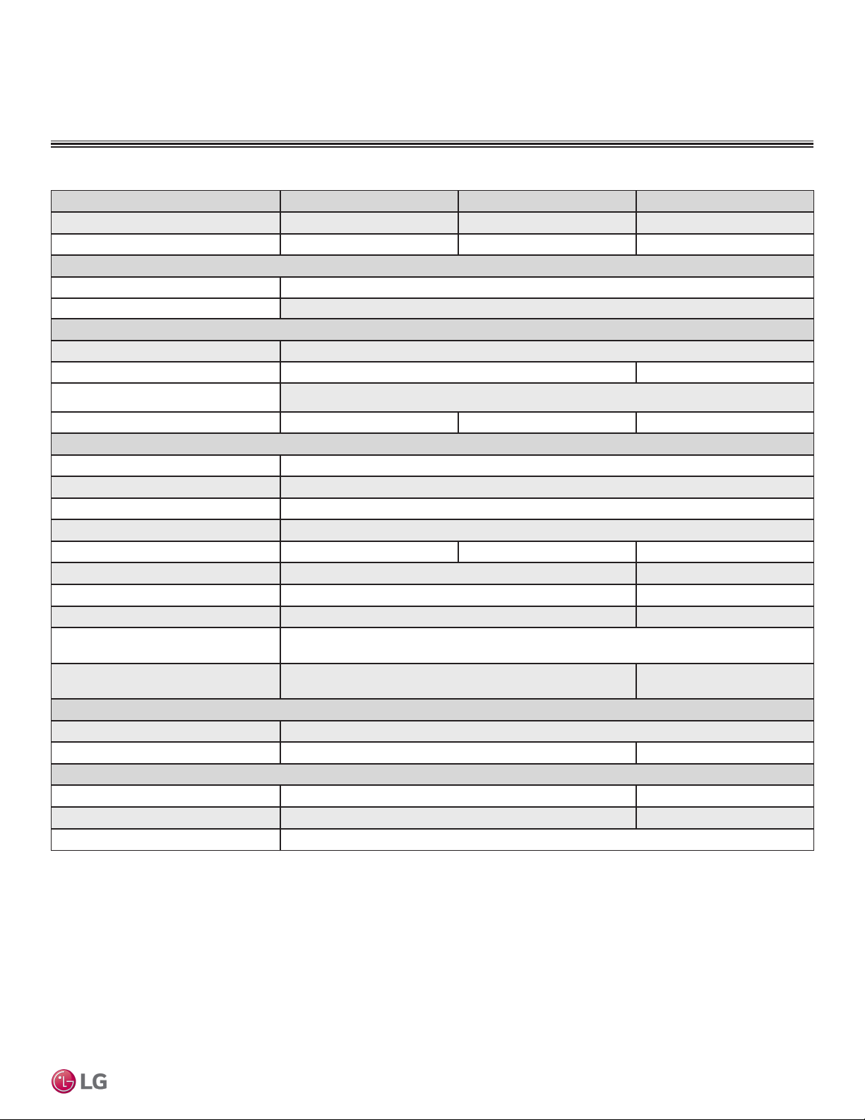
Table 3: Multi F Art Cool Mirror Indoor Unit General Data.
Model Name LAN090HSV5 LAN120HSV5 LAN180HSV5
Nominal Cooling Capacity (Btu/h)
Nominal Heating Capacity (Btu/h)
Operating Range
Cooling (°F WB)
Heating (°F DB)
Fan
Type
Motor Output (W) x Qty.
1
1
General Data / Specications
9,000 12,000 18,000
10,900 13,600 21,600
57-77
59-81
Cross Flow
30 x 1 60.0 x 1
Motor/Drive
Airflow Rate CFM (H/M/L)
Unit Data
Refrigerant Type
2
Refrigerant Control
Power Supply V, Ø, Hz3
Rated Amps (A)
Sound Pressure Level ±3 dB(A) (H/M/L)4
Dimensions (W x H x D, in.)
Net Unit Weight (lbs.)
Shipping Weight (lbs.)
Power Wiring / Communications Cable
(No. x AWG)5
Heat Exchanger
(Row x Column x Fin / inch) x Number
Pipe Size
Liquid (in.)
Vapor (in.)
Connection Size
Liquid (in.)
Vapor (in.)
Drain O.D. / I.D. (in.)
Brushless Digitally Controlled / Direct
268 / 218 / 169 282 / 233 / 177 558 / 438 / 353
R410A
EEV
208-230, 1, 60
0.4
36 / 32 / 27 38 / 34 / 29 44 / 38 / 34
32-15/16 x 12-1/8 x 7-9/16 39-9/32 x 13-19/32 x 8-11/32
20.5 29.8
25.6 36.4
4 x 18
(2 x 23 x 22) x 1 (2 x 16 x 20) x 1
1/4
3/8 1/2
1/4 3/8
3/8 5/8
27/32, 5/8
Art Cool Mirror™
1
accordance with standard length of each outdoor unit and a 0 ft. level difference between outdoor and
indoor units. All capacities are net with a combination ratio between 95 – 105%.
Nominal cooling capacity rating obtained with air entering the indoor unit at 80ºF dry bulb (DB) and 67ºF
wet bulb (WB) and outdoor ambient conditions of 95ºF dry bulb (DB) and 75ºF wet bulb (WB).
Nominal heating capacity rating obtained with air entering the indoor unit at 70ºF dry bulb (DB) and 60ºF
wet bulb (WB) and outdoor ambient conditions of 47ºF dry bulb (DB) and 43ºF wet bulb (WB).
2
Nominal capacity is rated 0 ft. above sea level with corresponding refrigerant piping length in
This unit comes with a dry helium charge.
Due to our policy of continuous product innovation, some specications may change without notication.
©LG Electronics U.S.A., Inc., Englewood Cliffs, NJ. All rights reserved. “LG” is a registered trademark of LG Corp.
3
Acceptable operating voltage: 187V-253V.
4
Sound pressure levels are tested in an anechoic chamber under ISO Standard 3745 and are the
same in both cooling and heating mode. These values can increase due to ambient conditions during
operation.
5
All power wiring / communications cable to the IDUs be minimum 18 AWG, 4-conductor, stranded,
shielded or unshielded (if shielded, must be grounded to chassis at ODU only) and must comply with
applicable local and national codes.
ART COOL M IRROR | 11
Page 12
ART COOL MIRROR INDOOR UNITS
MULTI
F
MAX
MULTI
F
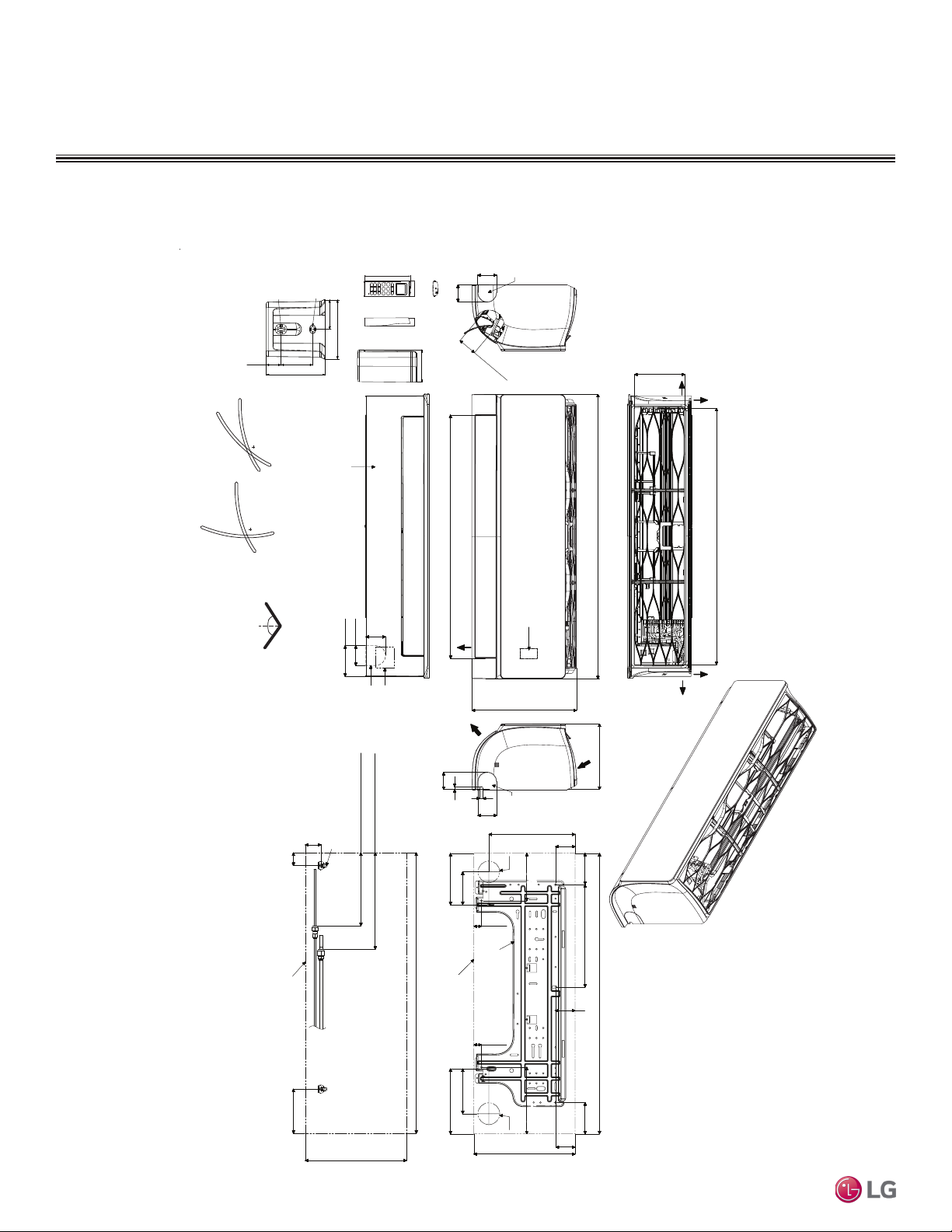
Dimensions
Figure 2: LAN090HSV5 and LAN120HSV5 Dimensions.
Refrigerant, Drain
Pipe, and Cable
Knock Out Hole
1/8 (3) x 1/4 (6)
1/4 (6) x 1/8 (3)
1-1/4 (31)
2-7/16 (61.5)
5-31/32 (152)
1-3/32 (50.2)
1-1/16 (26.2)
2-7/32 (56)
2 (51)
Unit : inch (mm)
Air Outlet Hole
Air Outlet Hole
[28-5/32 (715)]
Bottom
Air Outlet
2 (51)
5/16 (8)
11/32 (9)
2-7/32(56)
5-31/32 (152)
3-27/32 (98)
2-7/32 (56)
12-1/8 (308)
10-11/32 (263)
Ø2-9/16 (65)
Display & Remote
Controller Signal
Receiver Signal
Refrigerant,
Drain Pipe
and Cable
Knock
Out Hole
2-17/32 (64)
5-19/32 (142)
85°
45°
15°
15°
5/8 (15.3)
55°
55°
1-9/32 (32.7)
(61)
2-13/32
* If airflow direction control is available,
Cooling Heating
1-27/32(47)
1-1/2 (38)
Up & Down Left & Right
Connection
Decoration Cover
3-5/8 (92)
2-3/8 (60)
2-5/16
(59)
Refrigerant, Drain
Pipe and Cable
Knock Out Hole
Approx. 8-19/32 (218) to liquid pipe
Drain Hose
1-7/16 (33.5)
Terminal Block for
Power Supply and
Communication
Approx. 11-11/32 (288) to gas pipe
Multi F and Multi F MAX Indoor Unit Engineering Manual
32-15/16 (837)
Air Intake
7-9/16 (192)
3-21/32 (93)
[5-29/32 (150)]
Air Intake Hole
Left
Right
Rear
Air Intake Hole
[30-3/16 (767)]
Rear
12 | ART COO L MIRROR
29/32 (23)
Unit Outline
29/32 (23)
5-9/32 (134)
7-5/8 (194)
Installation Plate
7-27/32 (199)7-27/32 (199)5-19/32 (142)
Ø2-9/16 (65)
12-1/8 (308)
Fixing the Installation Plate, Drilling Hole
Connecting Gas/Liquid Pipe
Unit Outline
5-3/16 (132)
12-1/8 (308)
Due to our policy of continuous product innovation, some specications may change without notication.
©LG Electronics U.S.A., Inc., Englewood Cliffs, NJ. All rights reserved. “LG” is a registered trademark of LG Corp.
32-15/16 (837)
In Case of Left Side Piping
12-1/16 (306)
32-15/16 (837)
2-15/32
(63)
3-11/16 (94)
2-15/32 (63)
Page 13
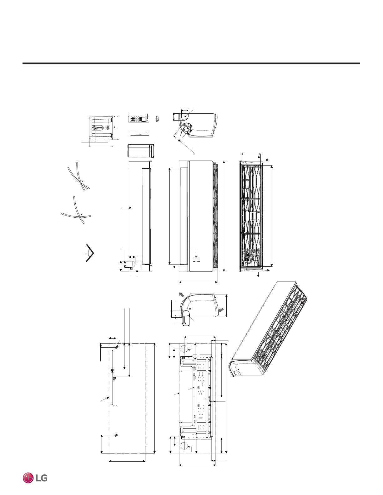
Figure 3: LAN180HSV5 Dimensions.
MULTI
F
MAX
MULTI
F
1/8 (3) x 1/4 (6)
5/8 (15.3)
1-9/32 (32.7)
2-13/32
15°
45°
Cooling Heating
1/4 (6) x 1/8 (3)
(61)
If airflow direction control is available,*
1-1/4 (31)
2-7/16 (61.5)
ART COOL MIRROR INDOOR UNITS
Dimensions
Refrigerant, Drain
Pipe, and Cable
Knock Out Hole
5-31/32 (152)
1-3/32 (50.2)
1-1/16 (26.2)
1-7/16 (33.5)
2-3/8 (60)
2-3/8 (60)
A le
ir Outlet Ho
[2-29/32 (74)]
[6-11/16 (170)]
Air Intake Hole
Left
Rear
Unit : inch (mm)
85°
20°
Up & Down Left & Right
50°
50°
2-15/32 (63)
1-15/32 (37)
Connecting Gas/Liquid Pipe
Unit Outline
Decoration Cover
3-17/32 (90)
2-1/4 (57)
2-7/32 (56)
Refrigerant, Drain
Pipe and Cable
Knock Out Hole
Drain Hose Connection
Terminal Block for
Power Supply and
Communication
Approx. 6-5/16 (160) to liquid pipe
Approx. 9-7/16 (240) to gas pipe
39-9/32 (998)
[34-11/32 (872)]
Air Outlet Hole
Display & Remote
Controller Signal
Receiver Signal
Bottom
13-19/32 (345)
Air
Outlet
2-3/8 (60)
7/16 (11)
Drain Pipe
and Cable
Knock
7/16(11)
5-9/32 (134)
3-9/32 (83)
Fixing the Installation Plate, Drilling Hole
Unit Outline
Out Hole
2-3/8 (60)
11-13/16 (300)
5-29/32 (150)5-29/32 (150)
Ø2-9/16 (65)
1-1/16 (27)
Installation Plate
Air Intake
Refrigerant,
2-3/32 (53)
14-11/16 (373)
2-23/32 (69)
39-9/32 (998)
4-17/32 (115)
8-11/32 (212)
39-9/32 (998)
Right
[36-5/32 (918)]
Air Intake Hole
Rear
Art Cool Mirror™
In case of Left Side Piping
6-15/32 (164)
13-19/32 (345)
Due to our policy of continuous product innovation, some specications may change without notication.
©LG Electronics U.S.A., Inc., Englewood Cliffs, NJ. All rights reserved. “LG” is a registered trademark of LG Corp.
1-1/16 (27)
3-9/32 (83)
5-29/32 (150)
7-13/32 (188)
7-13/32 (188)
Ø2-9/16 (65)
13-19/32 (345)
5-13/32 (137)
2-3/32 (53)
ART COOL M IRROR | 13
Page 14
ART COOL MIRROR INDOOR UNITS
MULTI
F
MAX
MULTI
F
Cooling Capacity Table
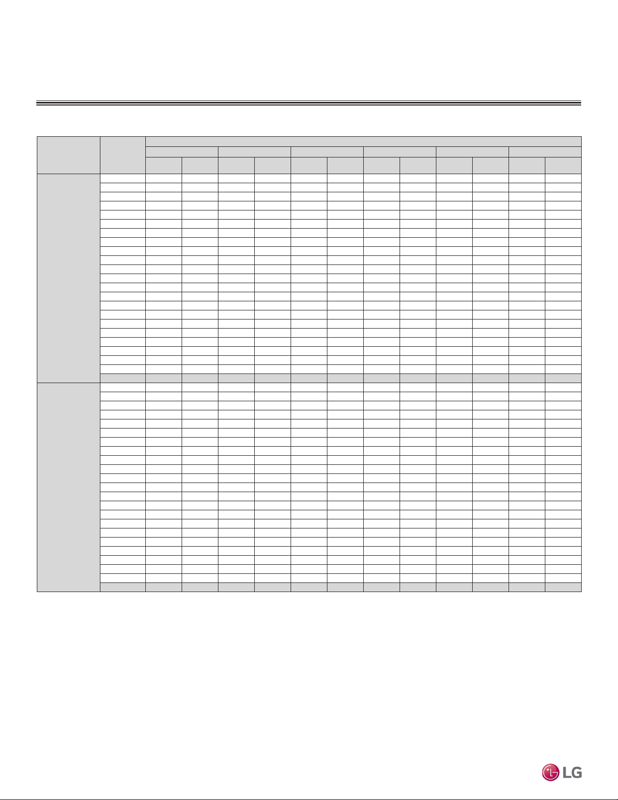
Table 4: Multi F Art Cool Mirror Indoor Units Cooling Capacity Table.
Model No. /
Nominal Capacity
of Indoor Unit
(Btu/h)
LAN090HSV5
9,000
LAN120HSV5
12,000
Multi F and Multi F MAX Indoor Unit Engineering Manual
TC = Total Capacity (kBtu/h).
SHC: Sensible Heat Capacity (kBtu/h).
Nominal capacity as rated 0 ft. above sea level and a 0 ft. level difference between outdoor and indoor units. Corresponding refrigerant piping length is accordance with standard length of each outdoor unit.
Nominal cooling capacity rating obtained with air entering the indoor unit at 80ºF dry bulb (DB) and 67ºF wet bulb (WB), and outdoor ambient conditions of 95ºF dry bulb (DB) and 75ºF wet bulb (WB).
The shaded table columns and rows indicate reference data. When operating at this temperature, these values can be different if the system is not running consistently.
Outdoor Air
Temp.
(°F DB)
14 8.82 6.04 9.37 6.38 9.92 6.18 10.31 6.31 11.01 6.36 11.56 6.48
20 8.82 6.09 9.36 6.43 9.91 6.23 10.31 6.36 11.01 6.41 11.55 6.53
25 8.81 6.13 9.36 6.48 9.90 6.27 10.30 6.41 11.00 6.46 11.54 6.58
30 8.80 6.18 9.35 6.53 9.90 6.32 10.29 6.46 10.99 6.51 11.54 6.63
35 8.80 6.23 9.34 6.58 9.89 6.37 10.28 6.50 10.98 6.56 11.53 6.68
40 8.79 6.28 9.33 6.63 9.88 6.42 10.27 6.55 10.97 6.61 11.52 6.73
45 8.78 6.32 9.33 6.68 9.87 6.47 10.27 6.60 10.96 6.66 11.51 6.78
50 8.78 6.37 9.32 6.73 9.87 6.51 10.26 6.65 10.96 6.71 11.50 6.83
55 8.77 6.42 9.31 6.78 9.86 6.56 10.25 6.70 10.95 6.76 11.49 6.88
60 8.76 6.46 9.31 6.83 9.85 6.61 10.24 6.75 10.94 6.81 11.48 6.93
65 8.76 6.51 9.30 6.88 9.84 6.66 10.24 6.80 10.93 6.85 11.47 6.98
70 8.75 6.56 9.29 6.92 9.84 6.70 10.23 6.85 10.92 6.90 11.47 7.03
75 8.54 6.45 9.08 6.82 9.62 6.61 10.01 6.75 10.71 6.82 11.25 6.96
80 8.33 6.34 8.87 6.71 9.41 6.51 9.80 6.66 10.49 6.73 11.03 6.87
85 8.12 6.22 8.66 6.60 9.20 6.41 9.59 6.56 10.28 6.64 10.82 6.79
90 7.91 6.10 8.45 6.48 8.99 6.31 9.37 6.46 10.06 6.55 10.60 6.70
95 7.68 6.04 8.22 6.43 8.75 6.26 9.00 6.32 9.83 6.52 10.36 6.67
100 7.50 5.88 8.03 6.26 8.57 6.11 8.88 6.22 9.64 6.37 10.17 6.53
105 7.31 5.72 7.84 6.10 8.38 5.96 8.77 6.12 9.45 6.23 9.99 6.39
110 7.12 5.52 7.66 5.90 8.19 5.78 8.58 5.94 9.26 6.06 9.80 6.22
115 6.94 5.36 7.47 5.74 8.01 5.63 8.39 5.79 9.08 5.91 9.61 6.08
118 6.82 5.32 7.36 5.70 7.89 5.60 8.28 5.76 8.96 5.89 9.50 6.06
122 6.79 5.30 7.32 5.69 7.86 5.59 8.24 5.76 8.93 5.89 9.46 6.06
14 11.76 8.51 12.49 8.99 13.22 8.70 13.75 8.88 14.69 8.96 15.42 9.13
20 11.75 8.57 12.48 9.06 13.21 8.77 13.74 8.95 14.67 9.03 15.40 9.20
25 11.75 8.64 12.48 9.13 13.20 8.84 13.73 9.02 14.66 9.10 15.39 9.27
30 11.74 8.71 12.47 9.20 13.19 8.90 13.72 9.09 14.65 9.17 15.38 9.34
35 11.73 8.77 12.46 9.27 13.18 8.97 13.71 9.16 14.64 9.24 15.37 9.41
40 11.72 8.84 12.45 9.34 13.17 9.04 13.70 9.23 14.63 9.31 15.36 9.48
45 11.71 8.90 12.44 9.41 13.16 9.11 13.69 9.30 14.62 9.38 15.35 9.55
50 11.70 8.97 12.43 9.47 13.15 9.17 13.68 9.37 14.61 9.45 15.33 9.62
55 11.69 9.03 12.42 9.54 13.14 9.24 13.67 9.44 14.60 9.52 15.32 9.70
60 11.68 9.10 12.41 9.61 13.13 9.31 13.66 9.50 14.59 9.58 15.31 9.77
65 11.67 9.17 12.40 9.68 13.12 9.38 13.65 9.57 14.57 9.65 15.30 9.84
70 11.66 9.23 12.39 9.75 13.11 9.44 13.64 9.64 14.56 9.72 15.29 9.91
75 11.38 9.08 12.11 9.60 12.83 9.31 13.35 9.51 14.27 9.60 15.00 9.79
80 11.10 8.92 11.82 9.45 12.55 9.17 13.07 9.38 13.99 9.48 14.71 9.68
85 10.83 8.76 11.54 9.29 12.26 9.03 12.78 9.24 13.70 9.36 14.42 9.56
90 10.55 8.60 11.26 9.13 11.98 8.88 12.50 9.10 13.42 9.22 14.13 9.43
95 10.25 8.51 10.96 9.05 11.67 8.82 12.00 8.90 13.10 9.18 13.81 9.39
100 10.00 8.28 10.71 8.82 11.42 8.61 11.84 8.76 12.85 8.98 13.56 9.20
105 9.75 8.05 10.46 8.59 11.17 8.40 11.69 8.62 12.60 8.78 13.31 9.01
110 9.50 7.77 10.21 8.31 10.92 8.14 11.44 8.37 12.35 8.53 13.07 8.76
115 9.25 7.54 9.96 8.08 10.67 7.92 11.19 8.15 12.10 8.33 12.82 8.56
118 9.10 7.49 9.81 8.03 10.52 7.88 11.04 8.12 11.95 8.30 12.67 8.54
122 9.05 7.47 9.76 8.01 10.48 7.87 10.99 8.11 11.90 8.29 12.62 8.53
68 / 57 73 / 61 77 / 64 80 / 67 86 / 72 90 / 75
TC SHC TC SHC TC SHC TC SHC TC SHC TC SHC
Indoor Air Temp. °F DB / °F WB
14 | ART COO L MIRROR
Due to our policy of continuous product innovation, some specications may change without notication.
©LG Electronics U.S.A., Inc., Englewood Cliffs, NJ. All rights reserved. “LG” is a registered trademark of LG Corp.
Page 15
ART COOL MIRROR INDOOR UNITS
MULTI
F
MAX
MULTI
F
Cooling Capacity Table
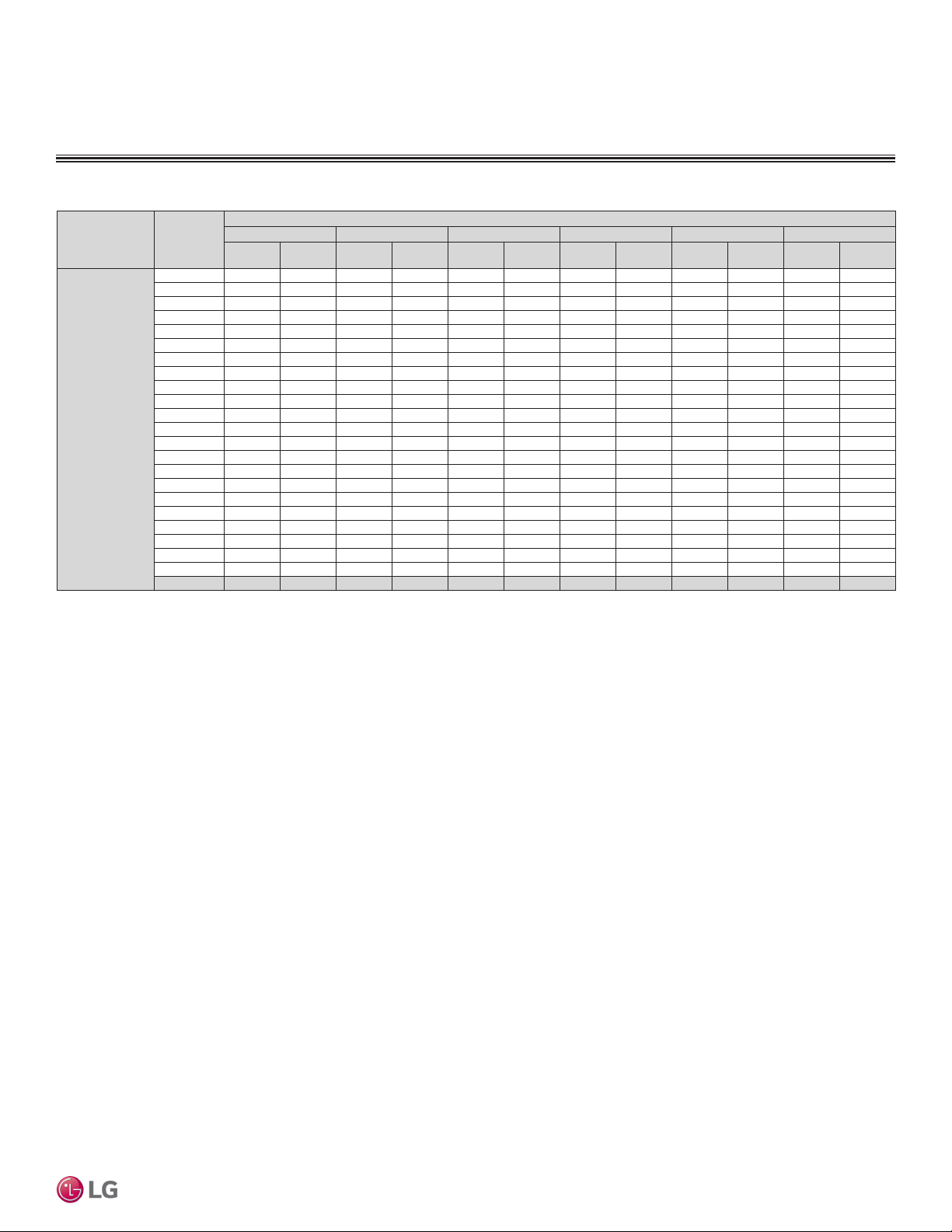
Table 5: Multi F Art Cool Mirror Indoor Units Cooling Capacity Table (continued).
Model No. /
Nominal Capacity
of Indoor Unit
(Btu/h)
LAN180HSV5
18,000
TC = Total Capacity (kBtu/h).
SHC: Sensible Heat Capacity (kBtu/h).
Nominal capacity as rated 0 ft. above sea level and a 0 ft. level difference between outdoor and indoor units. Corresponding refrigerant piping length is accordance with standard length of each outdoor unit.
Nominal cooling capacity rating obtained with air entering the indoor unit at 80ºF dry bulb (DB) and 67ºF wet bulb (WB), and outdoor ambient conditions of 95ºF dry bulb (DB) and 75ºF wet bulb (WB).
The shaded table columns and rows indicate reference data. When operating at this temperature, these values can be different if the system is not running consistently.
Outdoor Air
Temp.
(°F DB)
14 17.65 12.33 18.74 13.02 19.84 12.61 20.63 12.88 22.03 12.98 23.12 13.23
20 17.63 12.43 18.73 13.13 19.82 12.71 20.61 12.98 22.01 13.09 23.11 13.33
25 17.62 12.52 18.71 13.23 19.81 12.81 20.60 13.08 22.00 13.19 23.09 13.44
30 17.60 12.62 18.70 13.33 19.79 12.91 20.58 13.18 21.98 13.29 23.07 13.54
35 17.59 12.71 18.68 13.43 19.78 13.00 20.57 13.28 21.96 13.39 23.05 13.64
40 17.58 12.81 18.67 13.53 19.76 13.10 20.55 13.38 21.94 13.49 23.04 13.75
45 17.56 12.90 18.66 13.63 19.75 13.20 20.53 13.48 21.93 13.59 23.02 13.85
50 17.55 13.00 18.64 13.73 19.73 13.30 20.52 13.58 21.91 13.69 23.00 13.95
55 17.54 13.10 18.63 13.83 19.72 13.39 20.50 13.68 21.89 13.79 22.98 14.05
60 17.52 13.19 18.61 13.93 19.70 13.49 20.49 13.78 21.88 13.89 22.97 14.16
65 17.51 13.29 18.60 14.03 19.69 13.59 20.47 13.87 21.86 13.99 22.95 14.26
70 17.50 13.38 18.58 14.13 19.67 13.69 20.46 13.97 21.84 14.09 22.93 14.36
75 17.08 13.16 18.16 13.92 19.24 13.49 20.03 13.79 21.41 13.92 22.50 14.20
80 16.66 12.93 17.74 13.70 18.82 13.30 19.60 13.60 20.98 13.75 22.06 14.03
85 16.24 12.70 17.32 13.47 18.40 13.09 19.17 13.40 20.55 13.56 21.63 13.85
90 15.82 12.46 16.90 13.23 17.97 12.88 18.75 13.19 20.12 13.37 21.20 13.67
95 15.37 12.33 16.44 13.12 17.51 12.78 18.00 12.90 19.65 13.30 20.72 13.61
100 14.99 12.00 16.06 12.78 17.13 12.47 17.77 12.70 19.28 13.01 20.35 13.33
105 14.62 11.67 15.69 12.45 16.76 12.17 17.53 12.50 18.90 12.73 19.97 13.05
110 14.24 11.27 15.32 12.05 16.39 11.79 17.16 12.13 18.53 12.36 19.60 12.70
115 13.87 10.93 14.94 11.71 16.01 11.48 16.79 11.82 18.15 12.07 19.22 12.41
118 13.65 10.85 14.72 11.64 15.79 11.42 16.56 11.77 17.93 12.03 19.00 12.37
122 13.57 10.83 14.64 11.62 15.71 11.40 16.49 11.75 17.85 12.01 18.92 12.36
68 / 57 73 / 61 77 / 64 80 / 67 86 / 72 90 / 75
TC SHC TC SHC TC SHC TC SHC TC SHC TC SHC
Indoor Air Temp. °F DB / °F WB
Art Cool Mirror™
Due to our policy of continuous product innovation, some specications may change without notication.
©LG Electronics U.S.A., Inc., Englewood Cliffs, NJ. All rights reserved. “LG” is a registered trademark of LG Corp.
ART COOL M IRROR | 15
Page 16
ART COOL MIRROR INDOOR UNITS
MULTI
F
MAX
MULTI
F
Heating Capacity Table
Table 6: Multi F Art Cool Mirror Indoor Units Heating Capacity Table.
Model No. /
Nominal Capacity of
Indoor Unit
(Btu/h)
LAN090HSV5
10,900
LAN120HSV5
13,600
LAN180HSV5
21,600
Multi F and Multi F MAX Indoor Unit Engineering Manual
TC = Total Capacity (kBtu/h).
Nominal capacity as rated 0 ft. above sea level and a 0 ft. level difference between outdoor and indoor units. Corresponding refrigerant piping length is accordance with standard length of each outdoor unit.
Nominal heating capacity rating obtained with air entering the indoor unit at 70ºF dry bulb (DB) and 60ºF wet bulb (WB), and outdoor ambient conditions of 47ºF dry bulb (DB) and 43ºF wet bulb (WB).
Outdoor Air Temp. Indoor Air Temp. °F DB
61 64 68 70 72 75
°F DB °F WB
0 -0.4 5.61 5.53 5.48 5.45 5.37 5.14
5 4.5 6.32 6.24 6.18 6.16 6.08 5.85
10 9 7.03 6.95 6.90 6.88 6.79 6.56
17 15 7.98 7.90 7.85 7.82 7.75 7.48
20 19 8.33 8.26 8.21 8.18 8.09 7.82
25 23 8.93 8.85 8.79 8.77 8.69 8.37
30 28 9.44 9.36 9.31 9.29 9.20 8.93
35 32 9.96 9.87 9.82 9.79 9.72 9.47
40 36 10.42 10.33 10.28 10.25 10.18 9.94
45 41 10.87 10.80 10.74 10.71 10.64 10.40
47 43 11.06 10.98 10.93 10.90 10.82 10.59
50 46 11.24 11.15 11.10 11.08 10.99 10.73
55 51 11.53 11.46 11.40 11.37 11.30 10.98
60 56 11.53 11.46 11.40 11.37 11.30 11.03
63 59 11.53 11.46 11.40 11.37 11.30 11.06
68 64 11.53 11.46 11.40 11.37 11.30 11.11
0 -0.4 7.00 6.90 6.83 6.80 6.70 6.50
5 4.5 7.89 7.78 7.71 7.69 7.59 7.40
10 9 8.78 8.67 8.60 8.58 8.48 8.31
17 15 9.95 9.86 9.79 9.76 9.67 9.47
20 19 10.40 10.30 10.23 10.20 10.10 9.90
25 23 11.14 11.03 10.96 10.95 10.85 10.60
30 28 11.78 11.67 11.60 11.59 11.49 11.30
35 32 12.42 12.31 12.24 12.21 12.13 11.99
40 36 13.00 12.89 12.82 12.79 12.70 12.58
45 41 13.56 13.46 13.39 13.36 13.28 13.16
47 43 13.80 13.70 13.63 13.60 13.50 13.40
50 46 14.02 13.91 13.84 13.82 13.72 13.59
55 51 14.39 14.29 14.22 14.19 14.10 13.90
60 56 14.39 14.29 14.22 14.19 14.10 13.96
63 59 14.39 14.29 14.22 14.19 14.10 14.00
68 64 14.39 14.29 14.22 14.19 14.10 14.06
0 -0.4 11.11 10.96 10.85 10.80 10.64 10.18
5 4.5 12.52 12.37 12.26 12.21 12.06 11.58
10 9 13.93 13.77 13.67 13.61 13.46 12.99
17 15 15.81 15.65 15.55 15.49 15.34 14.84
20 19 16.51 16.36 16.25 16.20 16.04 15.49
25 23 17.69 17.53 17.43 17.37 17.22 16.59
30 28 18.70 18.55 18.44 18.39 18.24 17.69
35 32 19.72 19.56 19.46 19.41 19.25 18.79
40 36 20.63 20.48 20.37 20.32 20.17 19.70
45 41 21.55 21.39 21.29 21.24 21.08 20.61
47 43 21.91 21.76 21.65 21.60 21.44 20.98
50 46 22.26 22.11 22.01 21.95 21.80 21.27
55 51 22.86 22.70 22.59 22.53 22.38 21.76
60 56 22.86 22.70 22.59 22.53 22.38 21.85
63 59 22.86 22.70 22.59 22.53 22.38 21.91
68 64 22.86 22.70 22.59 22.53 22.38 22.02
TC TC TC TC TC TC
16 | ART C OOL MIR ROR
Due to our policy of continuous product innovation, some specications may change without notication.
©LG Electronics U.S.A., Inc., Englewood Cliffs, NJ. All rights reserved. “LG” is a registered trademark of LG Corp.
Page 17
ART COOL MIRROR INDOOR UNITS
MULTI
F
MAX
MULTI
F
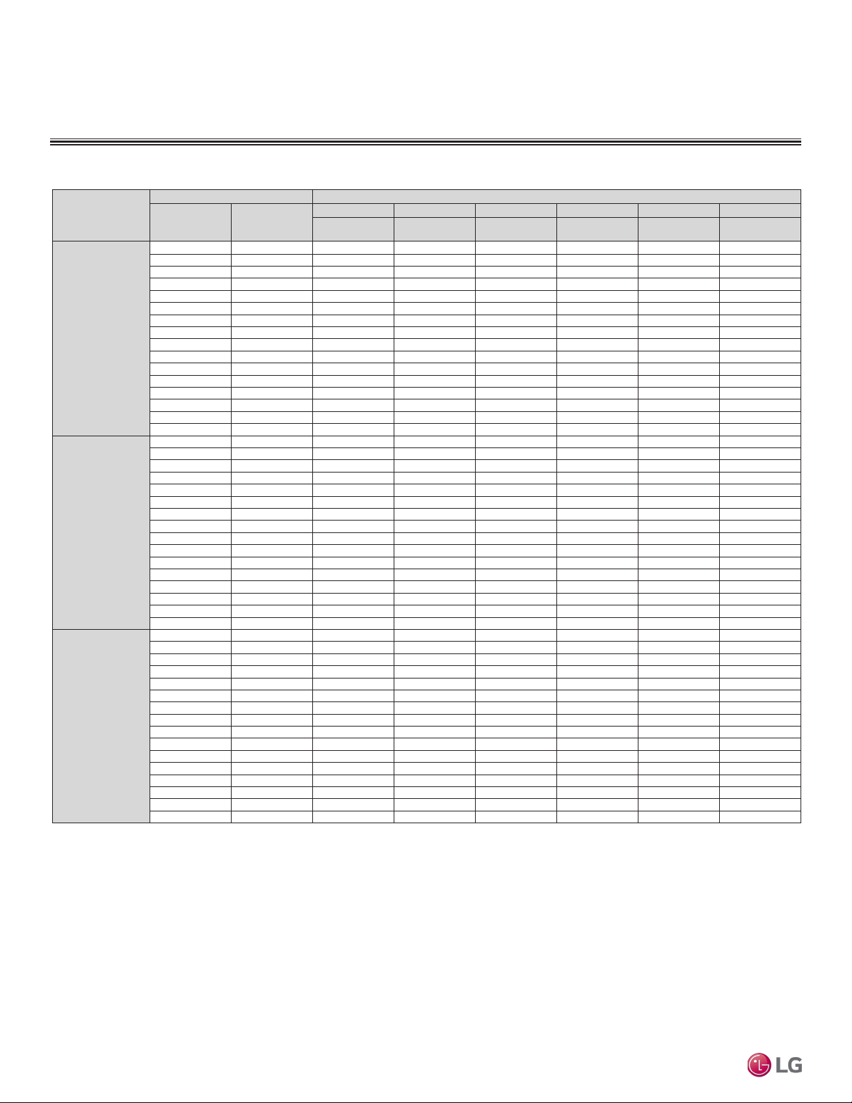
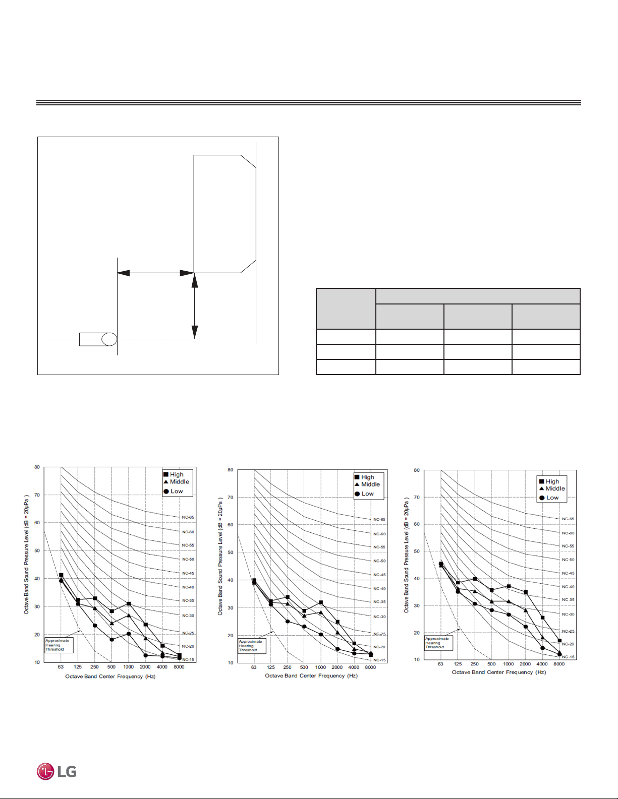
Acoustic Data
Figure 4: Sound Pressure Level Measurement Location.
3.3 ft.
2.6 ft.
Microphone
• Measurement taken 2.6′ below the bottom of the unit and at a
distance of 3.3′ from face of unit.
• Measurements taken with no attenuation and units operating at full
load normal operating condition.
• Sound level will vary depending on a range of factors such as
construction (acoustic absorption coefficient) of particular area in
which the equipment is installed.
• Sound power levels are measured in dB(A)±1.
• Tested in anechoic chamber per ISO Standard 3745.
Table 7: Sound Pressure Levels (dB[A]).
Sound Pressure Levels (dB[A]) (Cooling and Heating)
Model No.
LAN090HSV5 36 32 27
LAN120HSV5 38 34 29
LAN180HSV5 44 38 34
High Fan Speed
Medium Fan
Speed
Low Fan Speed
Art Cool Mirror™
Figure 5: Sound Pressure Level Diagrams.
LAN090HSV5 LAN120HSV5
LAN180HSV5
Due to our policy of continuous product innovation, some specications may change without notication.
©LG Electronics U.S.A., Inc., Englewood Cliffs, NJ. All rights reserved. “LG” is a registered trademark of LG Corp.
ART COOL M IRROR | 17
Page 18
ART COOL MIRROR INDOOR UNITS
MULTI
F
MAX
MULTI
F
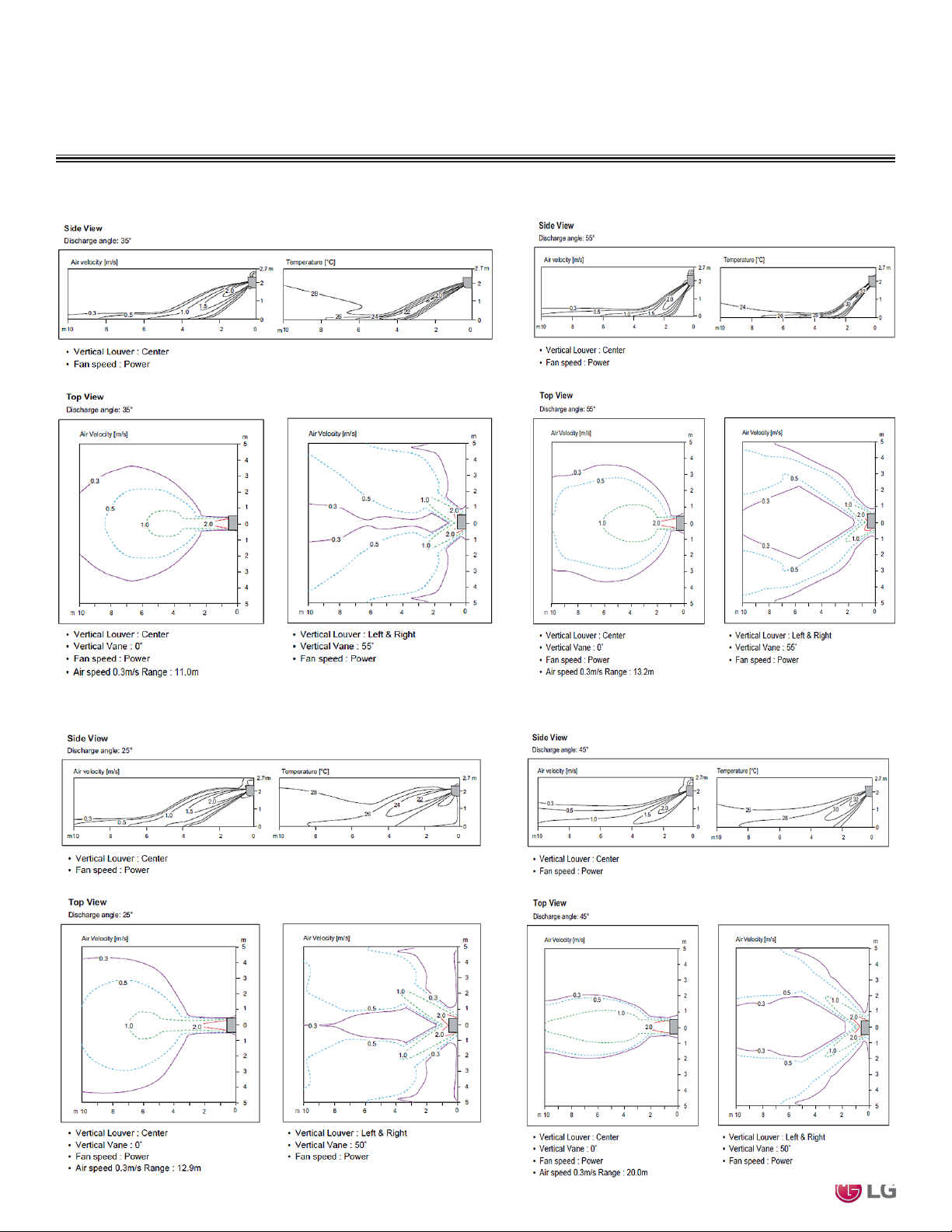
Air Velocity and Temperature Distribution
Figure 6: LAN090HSV5 and LAN120HSV5 Air Velocity and Temperature Distribution Charts.
Cooling
Heating
Figure 7: LAN180HSV5 Air Velocity and Temperature Distribution Charts.
Cooling
Multi F and Multi F MAX Indoor Unit Engineering Manual
Heating
18 | ART COOL MIR ROR
Due to our policy of continuous product innovation, some specications may change without notication.
©LG Electronics U.S.A., Inc., Englewood Cliffs, NJ. All rights reserved. “LG” is a registered trademark of LG Corp.
Page 19
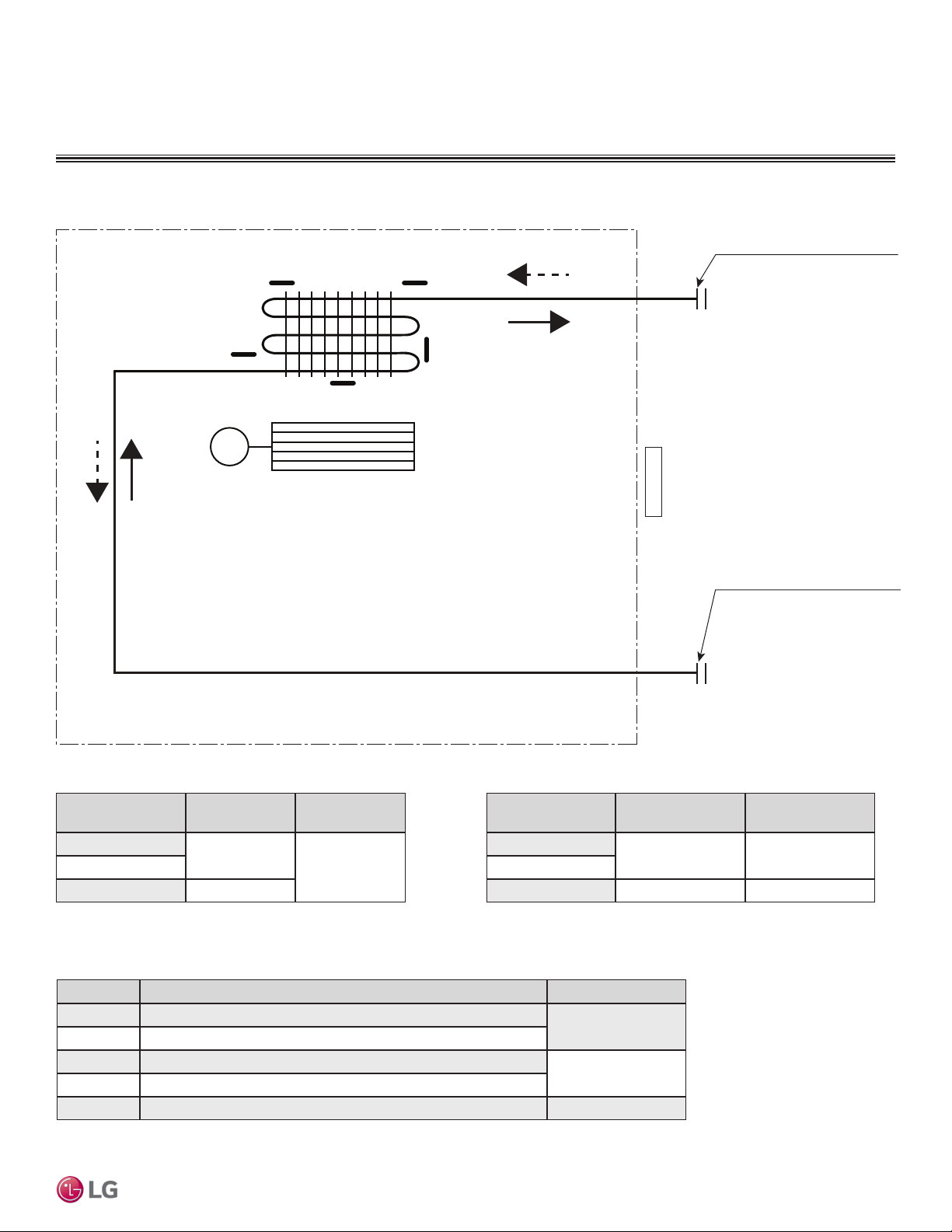
ART COOL MIRROR INDOOR UNITS
Vapor pipe connection port
Liquid pipe connection port
MULTI
F
MAX
MULTI
F
Figure 8: Art Cool Mirror Indoor Unit Refrigerant Flow Diagram.
Refrigerant Flow Diagram
M
Th2
Th1
Heat
Exchanger
Th3
Cross Flow Fan
Th4
Th5
Heating
(flare connection)
Cooling
Indoor Air Temperature
Thermistor for
Art Cool Mirror™
(flare connection)
Table 8: Art Cool Mirror Indoor Unit Refrigerant Pipe Sizes.
Table 10: Art Cool Mirror Indoor Unit Thermistor Details.
Table 9: Art Cool Mirror Indoor Unit Refrigerant Pipe Connections
Indoor Unit Capacity
9,000 Btu/h
18,000 Btu/h Ø1/2
Location Description (Based on Cooling Mode) IDU PCB Connector
Th1 Indoor Air Temperature Thermistor
Th2 Evaporator Inlet Temperature Thermistor
Th3 Evaporator Middle Temperature Thermistor
Th4 Evaporator Outlet Temperature Thermistor
Th5 Water Level Sensor (Optional) CN-TH3
Vapor Line Size
(in., OD)
Ø3/8
Liquid Line Size
(in., OD)
Ø1/412,000 Btu/h
Indoor Unit Capacity
9,000 Btu/h
12,000 Btu/h
18,000 Btu/h Ø5/8 Ø3/8
Connection (in., OD)
CN-TH1
CN-TH2
Due to our policy of continuous product innovation, some specications may change without notication.
©LG Electronics U.S.A., Inc., Englewood Cliffs, NJ. All rights reserved. “LG” is a registered trademark of LG Corp.
Vapor Line
Ø3/8 Ø1/4
Liquid Line
Connection (in., OD)
ART COOL M IRROR | 19
Page 20
ART COOL MIRROR INDOOR UNITS
MULTI
F
MAX
MULTI
F
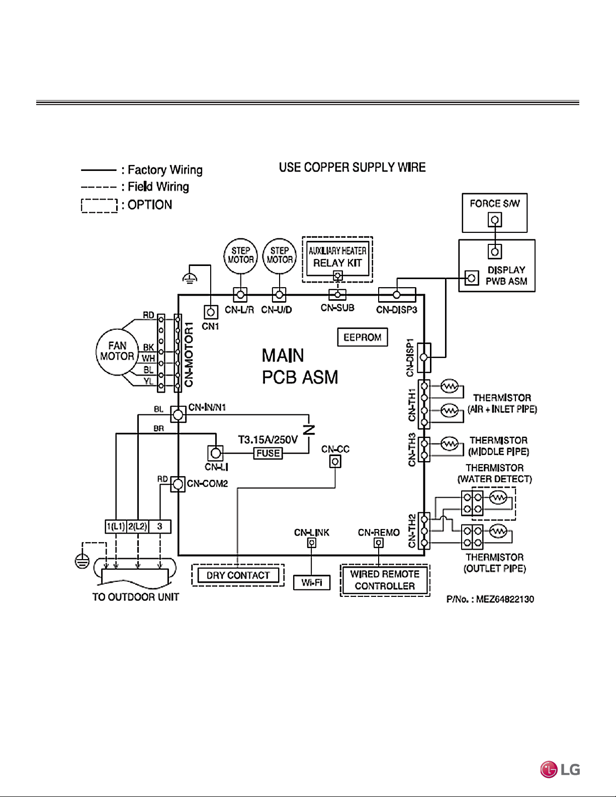
Wiring Diagram
Figure 9: Multi F Art Cool Mirror LAN090HSV5, LAN120HSV5, and LAN180HSV5 Indoor Units Wiring Diagram.
Multi F and Multi F MAX Indoor Unit Engineering Manual
20 | ART COOL M IRR OR
Due to our policy of continuous product innovation, some specications may change without notication.
©LG Electronics U.S.A., Inc., Englewood Cliffs, NJ. All rights reserved. “LG” is a registered trademark of LG Corp.
Page 21
Factory Supplied Parts
WARNING
MULTI
F
MAX
MULTI
F
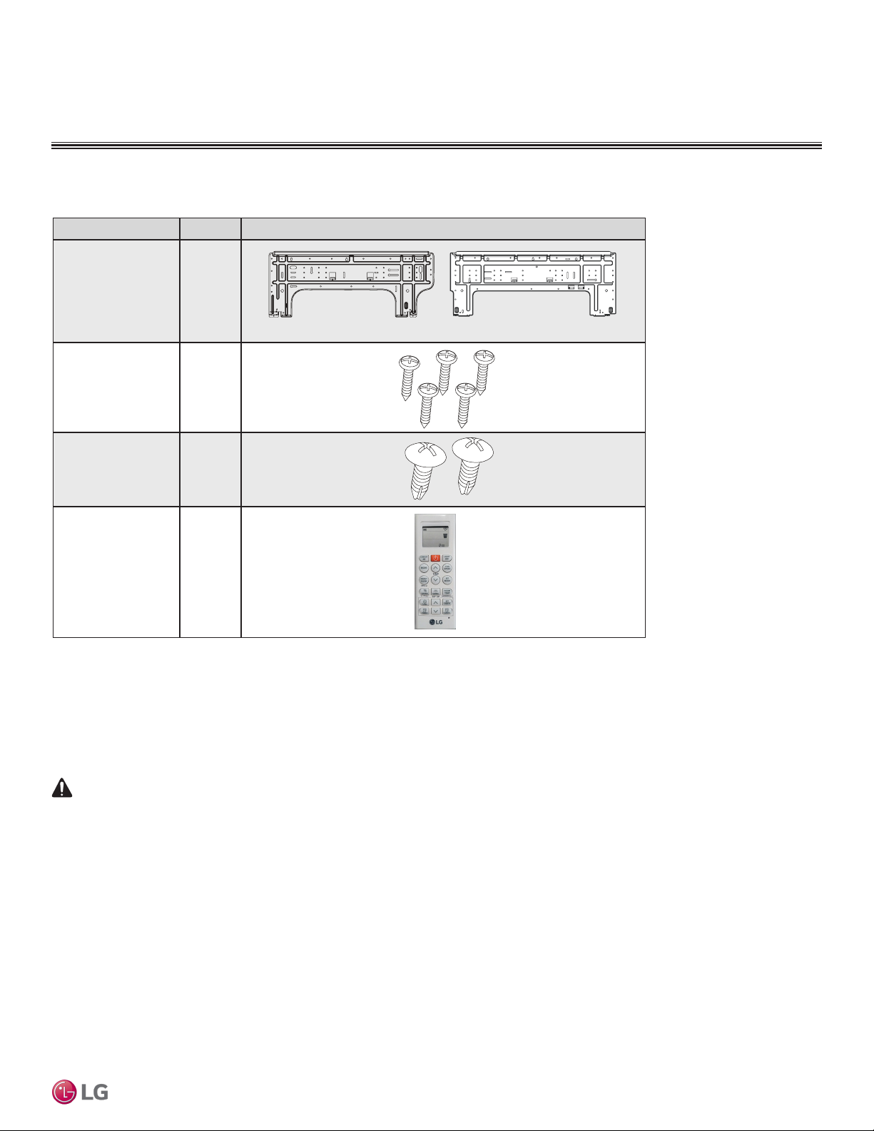
Table 11: Parts Table.
Part Quantity Image
Installation Plate One (1)
Type “A” Screws Five (5)
ART COOL MIRROR INDOOR UNITS
Factory Supplied Parts and Materials
LAN090HSV5 and LAN120HSV5 LAN180HSV5
Type “B” Screws
(M4 x 12L)
Wireless Handheld
Controller with Holder
AKB74955602
Factory Supplied Materials
• Owner’s Manual
• Installation Manual
Installation work must be performed by trained personnel and in accordance with national wiring standards and all local or other applicable codes.
Improper installation can result in re, electric shock, physical injury, or death.
Note:
Read all instructions before installing this product. Become familiar with the unit’s components and connections, and the order of installation. Incorrect
installation can degrade or prevent proper operation.
Two (2)
One (1)
Required Tools
• Level
• Screwdriver
• Electric drill
• Hole core drill
• Flaring tool set
• Spanner (Half union)
• Thermometer
Art Cool Mirror™
Due to our policy of continuous product innovation, some specications may change without notication.
©LG Electronics U.S.A., Inc., Englewood Cliffs, NJ. All rights reserved. “LG” is a registered trademark of LG Corp.
ART COOL M IRROR | 21
Page 22
ART COOL MIRROR INDOOR UNITS
DANGER
>4 inches
>4 inches
Ø2-3/4 inches
Place a level on raised tab
MULTI
F
MAX
MULTI
F
Installation and Best Layout Practices
To avoid the possibility of re, do not install the unit in an area where combustible gas may generate, ow, stagnate, or leak. Failure to do so will cause
serious bodily injury or death. Before beginning installation, read the safety summary at the beginning of this manual.
Select a location for installing the wall-mounted indoor unit (IDU) that meets the following conditions:
• Where there is enough structural strength to bear the weight of the unit
• Where air circulation will not be blocked
• Where noise prevention is taken into consideration
• Ensure there is sufficient space from the ceiling and floor
• Locate the indoor unit in a location where it can be easily connected to the outdoor unit/branch distribution unit
• Include space for drainage to ensure condensate flows properly out of the unit when it is in cooling mode
• Use a level indicator to ensure the unit is installed on a level plane
Note:
The unit may be damaged, may malfunction, and/or will not operate as designed if installed in any of the following conditions:
Do not install the unit where it will be subjected to direct thermal radiation from other heat sources.
Do not install the unit in an area where combustible gas may generate, flow, stagnate, or leak.
Do not install the unit in a location where acidic solution and spray (sulfur) are often used.
Do not use the unit in environments where oil, steam, or sulfuric gas are present.
Do not install additional ventilation products on the chassis of the unit.
Do not install the unit near high-frequency generator sources.
Do not install the unit near a doorway.
Installing in an Area Exposed to Unconditioned Air
In some installation applications, areas (floors, walls) in some rooms
may be exposed to unconditioned air (room may be above or next to
an unheated garage or storeroom). To countermeasure:
• Verify that carpet is or will be installed (carpet may increase the
temperature by three degrees).
• Add insulation between the floor joists.
• Install radiant heat or another type of heating system to the floor.
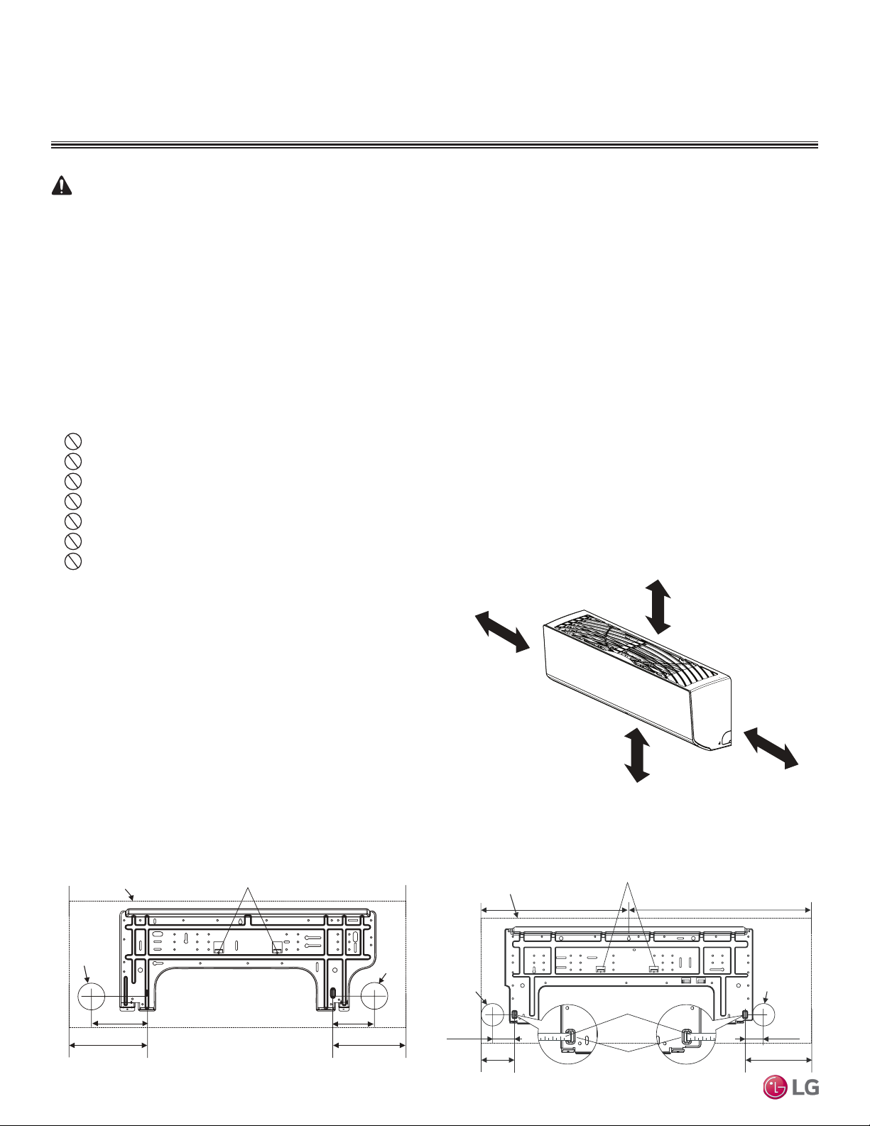
Figure 10:Minimum Clearance Requirements.
≥5 inches
Required Clearances
Figure 10 shows required clearance distances around a typical
installed wall-mounted unit.
Mounting the Installation Plate
The mounting wall should be strong and solid enough to protect the unit from vibration.
Multi F and Multi F MAX Indoor Unit Engineering Manual
• Mount the installation plate on the wall using the Type “A” screws. If mounting the unit on concrete, consider using anchor bolts.
• Always mount the installation plate horizontally. Measure the wall and mark the centerline using thread and a level.
Figure 11:Installation Plate for LAN090HSV5 and LAN120HSV5 Units. Figure 12:Installation Plate for LAN180HSV5 Units.
22 | ART CO OL MIRROR
Ø2-3/4 inches
Left rear piping
6-7/8 inches
Unit Outline
5-1/4 inches
Place a level on raised tab
Installation Plate
©LG Electronics U.S.A., Inc., Englewood Cliffs, NJ. All rights reserved. “LG” is a registered trademark of LG Corp.
Ø2-3/4
inches
Left rear
piping
3-3/4 inches
8-17/32 inches
Right rear piping
2-23/32 inches
Due to our policy of continuous product innovation, some specications may change without notication.
Recommended height
>6-1/2 feet from floor
Unit Outline
18-1/8 inches 22-7/16 inches
Installation Plate
Measuring Tape
4-1/8 inches
Measuring Tape Hanger
Ø2-3/4 inches
Right rear
piping
2-7/32 inches
8-5/32 inches
Page 23
ART COOL MIRROR INDOOR UNITS
Installation plate
Right
Tubing Clamp
Down
Left
Back
Frame Cover
(3/16"~5/16")
MULTI
F
MAX
MULTI
F
Installation and Best Layout Practices
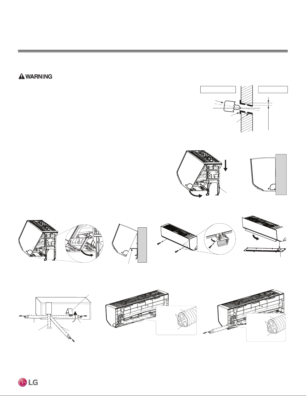
Drilling Piping Hole in the Wall
Use caution when drilling holes through walls. Drilling into power wiring in the wall can
cause serious bodily injury or death.
Follow the left or right piping clearance recommendations in Figure 3 or Figure 4.
1. Using a 2-5/8 (ø 65mm) inch hole core drill bit, drill a hole at either the right or
left side of the wall mounting. The hole should slant 3/16” to 5/16” from level
(upward on the indoor unit side and downward on the outdoor unit side).
2. Finish off the newly drilled hole as shown with bushing and sleeve covering.
Sleeve and bushing prevents damage to the tubing/bundling of the piping.
Figure 19:Drilling Piping Hole
Indoor
Core Drill
WALL
Outdoor
Bushing
Sleeve
Hanging the Indoor Unit Chassis
1. Attach the three (3) hooks on the top of the indoor unit to the top edge of
the installation plate. Verify the hooks are properly attached to the installation plate by gently shaking the indoor unit from side to side.
2. Unlock the tubing clamp from the indoor unit frame. For easier access be-
tween the bottom of the indoor unit and the wall, prop the clamp between
the indoor unit frame and installation plate.
3. Remove the screw covers at the bottom of the indoor unit, unscrew the
two (2) screws, remove the frame cover, remove the piping connection
cover, and position the piping for installation (down, back, left, or right).
Figure 14:Accessing the Back of the Indoor Unit.
Figure 15:Removing the Frame Cover.
Figure 13:Locking the Indoor Unit onto the Installation Plate.
Tubing Clamp
Figure 16:Exterior Back View of Indoor Unit. Figure 17:Piping Installed to the Left.
Art Cool Mirror™
Figure 18:Piping Installed to the Right.
Tape
Connecting
pipe
Drain hose
Due to our policy of continuous product innovation, some specications may change without notication.
©LG Electronics U.S.A., Inc., Englewood Cliffs, NJ. All rights reserved. “LG” is a registered trademark of LG Corp.
Tape
Connecting
pipe
Drain hose
ART COOL M IRROR | 23
Page 24
ART COOL MIRROR INDOOR UNITS
Terminal block
Power wiring /
communications cable
Wired Remote Controlle
r
Terminal (Optional)
Cable restraint
GRN / YLW
GRN / YLW
MULTI
F
MAX
MULTI
F
Installation and Best Layout Practices
Power Wiring / Communications Cable Guidelines
• Follow manufacturer’s circuit diagrams in the technical manuals.
• Confirm power source specifications.
• Confirm that the electrical capacity is sufficient.
• Starting current must be maintained ±10 percent of the rated current marked on the outdoor unit name plate.
• Confirm cable thickness specifications.
• It is recommended that a circuit breaker is installed, especially if conditions could become wet or moist.
• Include a disconnect in the power wiring system, add an air gap contact separation of at least 1/8 inch in each active (phase) conductor.
• Loose wiring may cause unit to malfunction, overheat, and catch fire, resulting in severe injury or death.
Note:
• Terminal screws may become loose during transport. Properly tighten the terminal connections during installation.
A voltage drop may cause the following problems:
• Magnetic switch vibration, fuse breaks, or disturbance to the normal function of an overload protection device.
• Compressor will not receive the proper starting current.
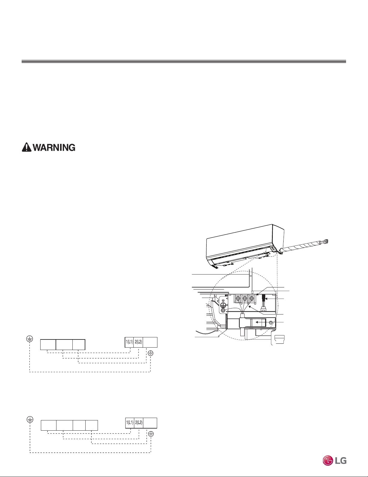
Connecting the Power Wiring and Communications Cable
1. Insert the power wiring/communications cable from the outdoor
unit or branch distribution unit (Multi F MAX systems only)
through the bottom of the indoor unit.
2. Connect each wire to its appropriate terminal on the indoor unit
control board. Verify that the color and terminal numbers from
the outdoor unit or branch distribution unit (Multi F MAX systems
only) wiring match the color and terminal numbers on the indoor
unit.
3. Secure the power wiring/communications cable with the cable
restraint.
Figure 21:Simplied View of Indoor Unit to Outdoor Unit / Branch
Distribution Unit Terminal Connections—LAN090HSV5 and
LAN120HSV5 models.
GND
Indoor Unit Terminal Block
Multi F and Multi F MAX Indoor Unit Engineering Manual
BR
32(L2)1(L1)
BL
RD
Outdoor Unit Terminal Block or
Branch Distribution Unit Terminal Block
(Multi F MAX Systems Only)
3 or S
GND
Figure 20:Connecting the Power Wiring / Communications Cable.
Figure 22:Simplied View of Indoor Unit to Outdoor Unit / Branch
Distribution Unit Terminal Connections—LAN180HSV5 models.
24 | ART COOL MIRROR
GND
Indoor Unit Terminal Block
1(L1 )2(L2)
BR
BL
Outdoor Unit Terminal Block or
Branch Distribution Unit Terminal Block
(Multi F MAX Systems Only)
3
RD
Due to our policy of continuous product innovation, some specications may change without notication.
©LG Electronics U.S.A., Inc., Englewood Cliffs, NJ. All rights reserved. “LG” is a registered trademark of LG Corp.
3 or S
GND
Page 25
Wireless Handheld Controller
MULTI
F
MAX
MULTI
F
Screen Display
ART COOL MIRROR INDOOR UNITS
Installation and Best Layout Practices
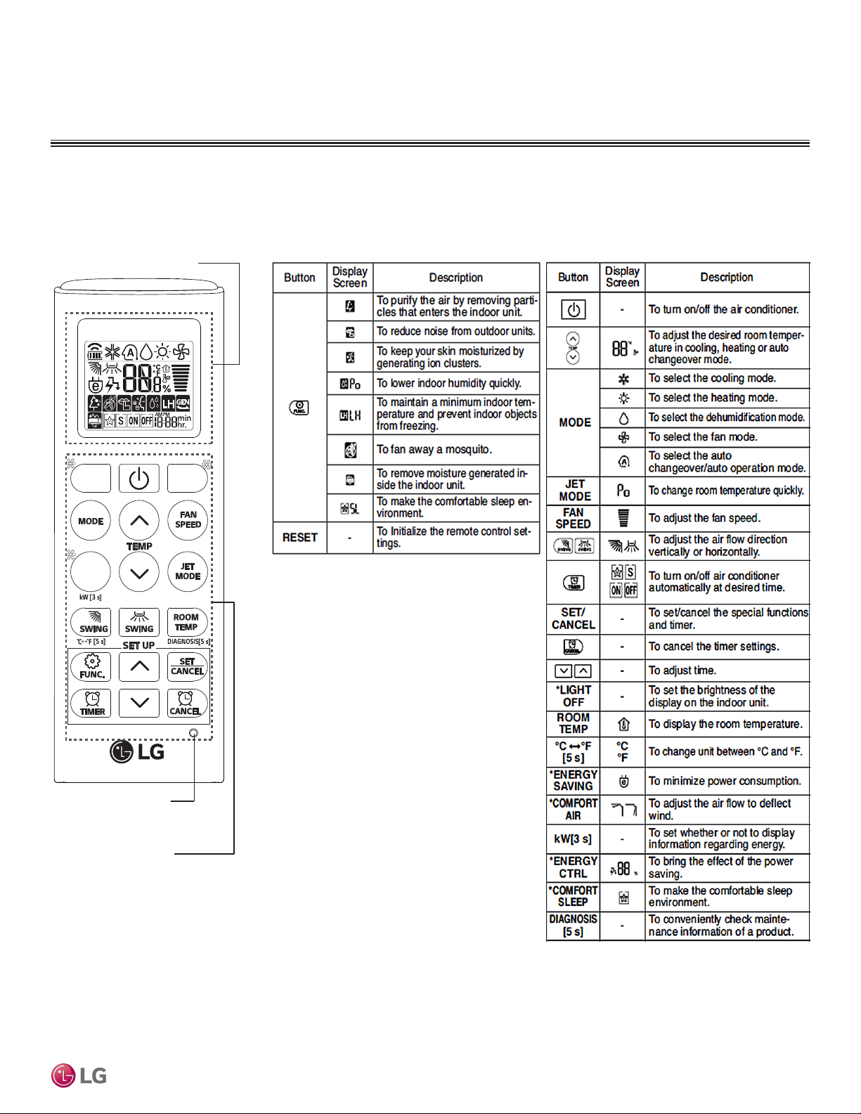
Table 12: AKB74955602 Wireless Controller Functions.Figure 23:AKB74955602 Wireless Controller.
*
*
RESET
Buttons
*
Art Cool Mirror™
Due to our policy of continuous product innovation, some specications may change without notication.
©LG Electronics U.S.A., Inc., Englewood Cliffs, NJ. All rights reserved. “LG” is a registered trademark of LG Corp.
ART COOL M IRROR | 25
Page 26
ART COOL MIRROR INDOOR UNITS
Indoor Unit Terminal Block
1(L1 )2(L2)
GND
GRN / YLW
BR
BL
RD
CN-REMO
To Outdoor Unit or Branch Distribution Unit
(Multi F MAX Systems Only)
To Wired Controller
3
Indoor Unit Terminal Block
1(L1 )2(L2)
GND
GRN / YLW
BR
BL
RD
CN-REMO
To Outdoor Unit or Branch Distribution Unit
(Multi F MAX Systems Only)
To Wired Controller
3
4 to 5 feet
above the floor
NO
NO
NO
YES
Remote Controller
TEMP
Remote Controller
TEMP
Re
m
ot
e
C
o
n
t
r
ol
l
er
TEMP
MULTI
F
MAX
MULTI
F
Installation and Best Layout Practices
Wired Controller Connections
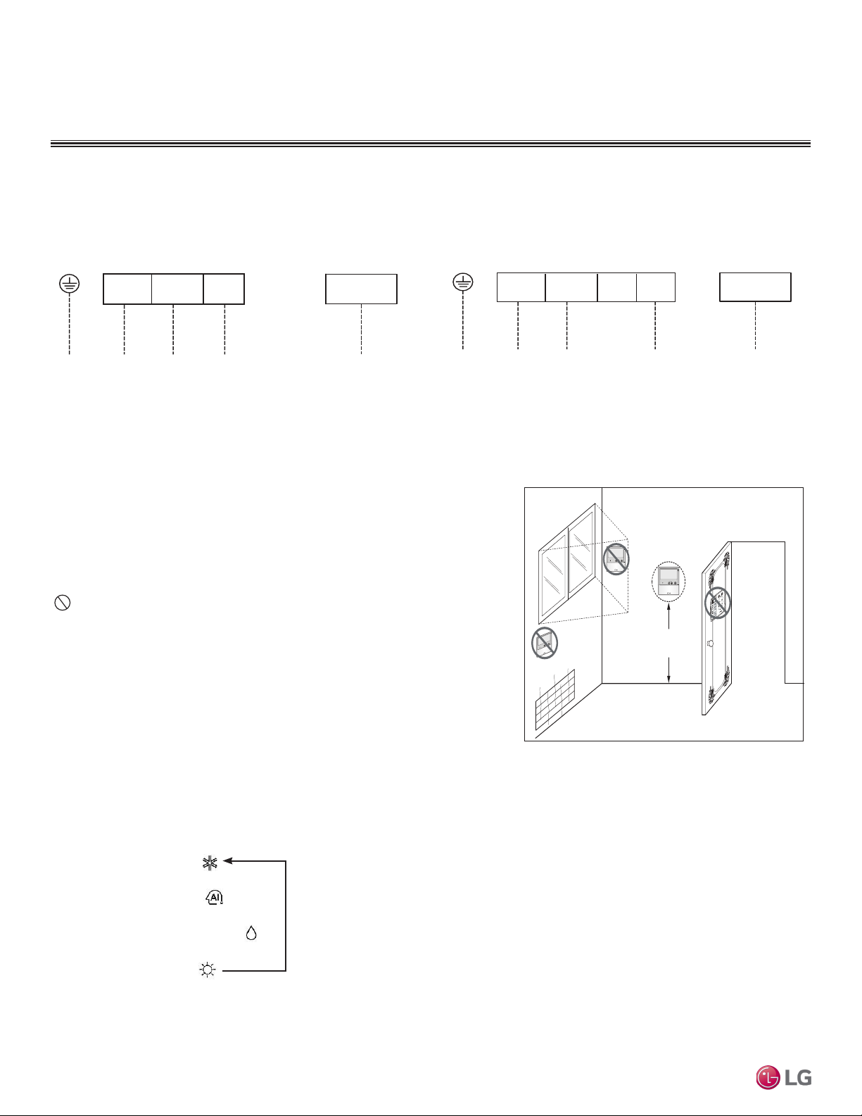
Figure 24:Wired Controller Connection on the Indoor Unit Terminal
Block—LAN090HSV5 and LAN120HSV5 models.
Figure 25:Wired Controller Connection on the Indoor Unit Terminal
Block—LAN180HSV5 models.
Wired Controller Placement
Wired controllers include a sensor to detect room temperature. To maintain comfort
levels in the conditioned space, the wired controller must be installed in a location
away from direct sunlight, high humidity, and where it could be directly exposed to
cold air. Controller must be installed four (4) to five (5) feet above the floor where its
LED display can be read easily, in an area with good air circulation, and where it can
detect an average room temperature.
Do not install the wired controller near or in:
• Drafts or dead spots behind doors and in corners
• Hot or cold air from ducts
• Radiant heat from the sun or appliances
• Concealed pipes and chimneys
• An area where temperatures are uncontrolled, such as an outside wall
Figure 26:Proper Location for the Wired Controller.
Multi F and Multi F MAX Indoor Unit Engineering Manual
Operation Mode Sequence
Cooling Mode
↓
Auto Operation
↓
26 | ART COOL MIRR OR
Dehumidification Mode
↓
Heating Mode
Due to our policy of continuous product innovation, some specications may change without notication.
©LG Electronics U.S.A., Inc., Englewood Cliffs, NJ. All rights reserved. “LG” is a registered trademark of LG Corp.
Page 27
ART COOL MIRROR INDOOR UNITS
Top
Wall Wa ll
Wall Wall
Installing the Controller
Removing the Controller
MULTI
F
MAX
MULTI
F
Installation and Best Layout Practices
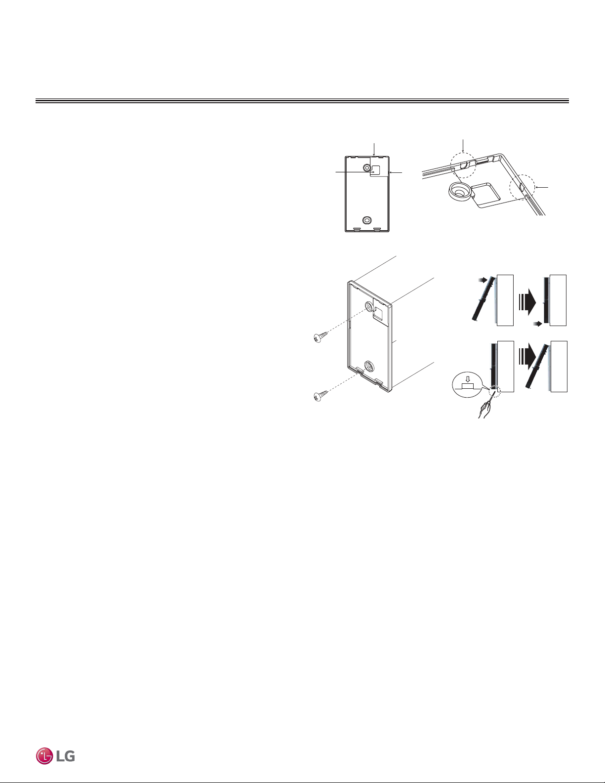
Hanging the Wired Controller
1. The controller wiring/cable can be installed in one of three direc-
tions: top, back, or on the right side. If top or right side installation
is desired, remove cable guide grooves on the controller, and
then position wiring/cable on applicable side.
2. Choose and mark the area of installation, and then screw the wall
plate into place (using the provided parts). Install the controller
wall plate to fit the electrical box if one is present. Ensure that no
gaps exist between the wall plate and the wall itself.
3. Arrange wiring/cables so as not to interfere with the controller
circuitry. Position the wired controller on the wall plate. Snap into
place by pressing the bottom part of the wired controller onto
the wall plate. Make sure that no gaps exist between the wired
controller and the wall plate on all sides.
4. To remove wired controller from the wall plate, insert a screwdriver into the two holes at the bottom. Twist screwdriver to
release controller. Do not damage the controller components
when removing.
Figure 27:Removing the Cable Guide Grooves.
Top
Back
Figure 28:Attaching the Wall Plate. Figure 29:Installing/Removing the
Right
Side
Controller.
Right
Side
Art Cool Mirror™
Assigning the Thermistor for Temperature Detection
Each indoor unit includes a return air thermistor assigned to sense the temperature. If a wired controller is installed, there is a choice of
sensing temperature with either the indoor unit return air thermistor or the thermistor in the wired controller. It is also an option to set both
thermistors to sense temperature so that indoor unit bases its operation on the first thermistor to reach the designated temperature differential. For applicable indoor units, an optional Remote Temperature Sensor can be used in lieu of the return air thermistor—either alone or in
conjunction with a wired controller thermistor as previously described.
Due to our policy of continuous product innovation, some specications may change without notication.
©LG Electronics U.S.A., Inc., Englewood Cliffs, NJ. All rights reserved. “LG” is a registered trademark of LG Corp.
ART COOL M IRROR | 27
Page 28

™
ART COO
L
GALLERY
INDOOR UNIT DATA
“Mechanical Specifications” on page 29
“General Data / Specifications” on page 30
“Dimensions” on page 31
“Cooling Capacity Table” on page 32
“Heating Capacity Table” on page 33
“Acoustic Data” on page 34
“Air Velocity and Temperature Distribution” on page 35
“Refrigerant Flow Diagram” on page 36
“Wiring Diagram” on page 37
“Factory Supplied Parts and Materials” on page 38
“Installation and Best Layout Practices” on page 39
Page 29
ART COOL GALLERY INDOOR UNITS
MULTI
F
MAX
MULTI
F
Mechanical Specications and Features
ART COOL Gallery Indoor Units
General
All LG indoor units are factory assembled, wired, piped, and provided with a control circuit board, fan, and motor. Art Cool Gallery
indoor units have a sound rating no higher than 42 dB(A) as tested
per KSA0701 ISO Standard 3745.
Coil
Indoor unit coils are comprised of a minimum of two rows of
aluminum fins mechanically bonded to copper tubing. The coils are
pressure tested at the factory. Each unit is provided with a factory
installed condensate drain pan below the coil.
Refrigerant System
System is designed for use with R410A refrigerant. The refrigeration
circuit is pressure-tested at the factory and shipped with a holding
charge of helium gas. Refrigerant pipe connections are 45° flare.
All refrigerant lines from the outdoor unit to the indoor units must be
field insulated.
Electrical
Each indoor unit is designed to operate using 208–230/60/1 power
with voltage variances of ±10%.
Casing
Units are designed to mount on a vertical surface, and are shipped
with a separate back plate that secures the unit to the wall, protruding no more than six (6) inches. Unit is designed so that refrigerant
piping can be installed in one of four different directions.
Cases / Finishes
The Art Cool Gallery unit has a frame that can accommodate a 20" x
20" photograph, picture or artwork. Unit casing has a gray finish and
is manufactured of heavy-duty acrylonitrile butadiene styrene (ABS)
and high impact polystyrene (HIPS) plastic.
Fan Assembly and Control
The unit has a single, direct-drive, crossflow fan made of high
strength ABS plastic. The fan motor is brushless digitally controlled
(BLDC) with permanently lubricated and sealed ball bearings. The
fan/motor assembly is mounted on vibration attenuating rubber
grommets. Fan speed is controlled using a microprocessor-based
direct digitally controlled algorithm that provides pre-programmed,
field-selectable fixed or auto fan speeds in the Heating and Cooling
modes. For Art Cool Gallery units, the indoor fan has Low, Med,
High, Power Cool and Auto settings for Cooling mode; and has Low,
Med, High, and Auto settings for Heating mode. The Auto setting
adjusts the fan speed based on the difference between the controller
setpoint and space temperature. Also, the separate Chaos setting
provides a simultaneous and random change in fan speed and flow
direction at the discharge,
simulating a natural outdoor
breeze.
Figure 30: Multi F Art Cool Gallery
Indoor Unit.
Air Filter
Return air is filtered with a
factory-supplied, removable,
washable pre-filter. Filter
access is from the front of
the unit without the use of
tools.
Airflow Guide Vanes
Motorized oscillating guide
vanes are factory installed,
and allows the ability to
control the direction of
airflow from side to side. A
motorized air sweep louver provides an automatic change in airflow
by directing the air up and down to provide uniform air distribution.
Microprocessor Control
The indoor unit is provided with an integrated control panel to
communicate with the outdoor unit. All unit operation parameters are
stored in non-volatile memory resident on the unit microprocessor.
The microprocessor controls space temperature through using the
value provided by the temperature sensor within the indoor unit.
The microprocessor control will activate indoor unit operation when
the indoor room temperature falls below or rises above a setpoint
temperature, at which point, a signal is sent to the outdoor unit to
begin the appropriate mode. The microprocessor will also provide
self-diagnostics and auto restart functions. A field-supplied fourwire power / communications cable must be installed to connect the
indoor unit(s) to the outdoor unit.
Controls
The indoor unit casing has a factory-standard, integral infrared
sensor designed to communicate with the supplied LG wireless
handheld remote controller. An optional LG supplied wired controller
is available as an additional accessory. Communication between the
indoor units and the outdoor unit is accomplished through 18 AWG,
four-core, stranded and shielded power / communication cable.
Condensate
The unit is designed for gravity draining of condensate and includes
a flexible drain hose capable of installation in one of two directions.
Unit includes a connection that is compatible with the AquaGuard®
AG-9300-LG condensate sensor.
Art Cool Gallery™
Features
• Inverter (Variable speed fan)
• Chaos swing
• Jet cool
• Group control
• Self-cleaning indoor coil
• Auto operation / auto restart operation
Due to our policy of continuous product innovation, some specications may change without notication.
©LG Electronics U.S.A., Inc., Englewood Cliffs, NJ. All rights reserved. “LG” is a registered trademark of LG Corp.
• 24-Hour on/off timer
• Wireless LCD remote control included;
wired thermostat available (sold separately)
ART COOL G ALLERY™ | 29
Page 30
ART COOL GALLERY INDOOR UNITS
MULTI
F
MAX
MULTI
F
Table 13: Multi F Art Cool Gallery Indoor Unit General Data.
Model Name LMAN097HVP LMAN127HVP
Nominal Cooling Capacity (Btu/h)
Nominal Heating Capacity (Btu/h)
1
1
Operating Range
Cooling (°F WB)
Heating (°F DB)
Fan
Type
Motor Output (W) x Qty.
Motor/Drive
Brushless Digitally Controlled / Direct Brushless Digitally Controlled / Direct
Airflow Rate CFM (H/M/L)
Unit Data
Refrigerant Type
2
Refrigerant Control
Power Supply V, Ø, Hz3
Rated Amps (A)
Sound Pressure Level ±3 dB(A) (H/M/L)4
Dimensions (W x H x D, in.)
23-5/8 x 23-5/8 x 5-25/32 23-5/8 x 23-5/8 x 5-25/32
Net Unit Weight (lbs.)
Shipping Weight (lbs.)
Power Wiring / Communications Cable
(No. x AWG)5
Heat Exchanger
(Row x Column x Fin / inch) x Number
Piping
Liquid (in.)
Vapor (in.)
Drain O.D. / I.D. (in.)
1
Nominal capacity is rated 0 ft. above sea level with corresponding refrigerant piping length in
accordance with standard length of each outdoor unit and a 0 ft. level difference between outdoor and
Multi F and Multi F MAX Indoor Unit Engineering Manual
indoor units. All capacities are net with a combination ratio between 95 – 105%.
Nominal cooling capacity rating obtained with air entering the indoor unit at 80ºF dry bulb (DB) and 67ºF
wet bulb (WB) and outdoor ambient conditions of 95ºF dry bulb (DB) and 75ºF wet bulb (WB).
Nominal heating capacity rating obtained with air entering the indoor unit at 70ºF dry bulb (DB) and 60ºF
wet bulb (WB) and outdoor ambient conditions of 47ºF dry bulb (DB) and 43ºF wet bulb (WB).
2
This unit comes with a dry helium charge.
9,000 11,200
10,400 13,300
57-77 57-77
59-81 59-81
Turbo Turbo
24 x 1 24 x 1
272 / 208 / 155 314 / 258 / 198
R410A R410A
EEV EEV
208-230, 1, 60 208-230, 1, 60
0.2 0.2
39 / 35 / 31 42 / 38 / 34
32 32
37 37
4 x 18 4 x 18
(2 x 20 x 21) x 1 (2 x 20 x 21) x 1
1/4 1/4
3/8 3/8
27/32, 5/8 27/32, 5/8
3
Acceptable operating voltage: 187V-253V.
4
Sound pressure levels are tested in an anechoic chamber under ISO Standard 3745 and are the
same in both cooling and heating mode. These values can increase due to ambient conditions during
operation.
5
All power wiring / communications cable to the IDUs be minimum 18 AWG, 4-conductor, stranded,
shielded or unshielded (if shielded, must be grounded to chassis at ODU only) and must comply with
applicable local and national codes.
General Data / Specications
30 | ART CO OL GALLERY™
Due to our policy of continuous product innovation, some specications may change without notication.
©LG Electronics U.S.A., Inc., Englewood Cliffs, NJ. All rights reserved. “LG” is a registered trademark of LG Corp.
Page 31

ART COOL GALLERY INDOOR UNITS
MULTI
F
MAX
MULTI
F
Figure 31: LMAN097HVP and LMAN127HVP Dimensions.
Dimensions
Supply Air Vane
Supply
Air
Supply Air Vane
Supply Air
Art Cool Gallery™
Supply Air Vane
Supply
Air
Return Air Inlet
Discharge Air Grille
Due to our policy of continuous product innovation, some specications may change without notication.
©LG Electronics U.S.A., Inc., Englewood Cliffs, NJ. All rights reserved. “LG” is a registered trademark of LG Corp.
ART COOL G ALLERY™ | 31
Page 32
ART COOL GALLERY INDOOR UNITS
MULTI
F
MAX
MULTI
F
Cooling Capacity Table
Table 14: Multi F Art Cool Gallery Indoor Units Cooling Capacity Table.
Model No. /
Nominal Capacity
of Indoor Unit
(Btu/h)
LMAN097HVP
9,000
LMAN127HVP
12,000
Multi F and Multi F MAX Indoor Unit Engineering Manual
TC = Total Capacity (kBtu/h).
SHC: Sensible Heat Capacity (kBtu/h).
Nominal capacity as rated 0 ft. above sea level and a 0 ft. level difference between outdoor and indoor units. Corresponding refrigerant piping length is accordance with standard length of each outdoor unit.
Nominal cooling capacity rating obtained with air entering the indoor unit at 80ºF dry bulb (DB) and 67ºF wet bulb (WB), and outdoor ambient conditions of 95ºF dry bulb (DB) and 75ºF wet bulb (WB).
The shaded table columns and rows indicate reference data. When operating at this temperature, these values can be different if the system is not running consistently.
Outdoor Air
Temp.
(°F DB)
14 8.82 5.68 9.37 6.00 9.92 5.81 10.31 5.93 11.01 5.98 11.56 6.09
20 8.82 5.72 9.36 6.04 9.91 5.85 10.31 5.98 11.01 6.03 11.55 6.14
25 8.81 5.77 9.36 6.09 9.90 5.90 10.30 6.02 11.00 6.07 11.54 6.19
30 8.80 5.81 9.35 6.14 9.90 5.94 10.29 6.07 10.99 6.12 11.54 6.23
35 8.80 5.85 9.34 6.18 9.89 5.99 10.28 6.11 10.98 6.17 11.53 6.28
40 8.79 5.90 9.33 6.23 9.88 6.03 10.27 6.16 10.97 6.21 11.52 6.33
45 8.78 5.94 9.33 6.28 9.87 6.08 10.27 6.21 10.96 6.26 11.51 6.38
50 8.78 5.99 9.32 6.32 9.87 6.12 10.26 6.25 10.96 6.30 11.50 6.42
55 8.77 6.03 9.31 6.37 9.86 6.17 10.25 6.30 10.95 6.35 11.49 6.47
60 8.76 6.07 9.31 6.42 9.85 6.21 10.24 6.34 10.94 6.40 11.48 6.52
65 8.76 6.12 9.30 6.46 9.84 6.26 10.24 6.39 10.93 6.44 11.47 6.56
70 8.75 6.16 9.29 6.51 9.84 6.30 10.23 6.43 10.92 6.49 11.47 6.61
75 8.54 6.06 9.08 6.41 9.62 6.21 10.01 6.35 10.71 6.41 11.25 6.54
80 8.33 5.96 8.87 6.31 9.41 6.12 9.80 6.26 10.49 6.33 11.03 6.46
85 8.12 5.85 8.66 6.20 9.20 6.03 9.59 6.17 10.28 6.24 10.82 6.38
90 7.91 5.74 8.45 6.09 8.99 5.93 9.37 6.07 10.06 6.16 10.60 6.30
95 7.68 5.68 8.22 6.04 8.75 5.88 9.00 5.94 9.83 6.12 10.36 6.27
100 7.50 5.52 8.03 5.89 8.57 5.74 8.88 5.85 9.64 5.99 10.17 6.14
105 7.31 5.37 7.84 5.73 8.38 5.60 8.77 5.76 9.45 5.86 9.99 6.01
110 7.12 5.19 7.66 5.55 8.19 5.43 8.58 5.58 9.26 5.69 9.80 5.85
115 6.94 5.03 7.47 5.39 8.01 5.29 8.39 5.44 9.08 5.56 9.61 5.71
118 6.82 5.00 7.36 5.36 7.89 5.26 8.28 5.42 8.96 5.54 9.50 5.70
122 6.79 4.98 7.32 5.35 7.86 5.25 8.24 5.41 8.93 5.53 9.46 5.69
14 10.98 7.06 11.66 7.46 12.34 7.22 12.84 7.38 13.71 7.44 14.39 7.58
20 10.97 7.12 11.65 7.52 12.33 7.28 12.83 7.43 13.70 7.50 14.38 7.64
25 10.96 7.17 11.64 7.58 12.32 7.34 12.82 7.49 13.69 7.55 14.37 7.70
30 10.95 7.23 11.63 7.64 12.31 7.39 12.81 7.55 13.68 7.61 14.36 7.76
35 10.95 7.28 11.63 7.69 12.31 7.45 12.80 7.61 13.66 7.67 14.34 7.82
40 10.94 7.34 11.62 7.75 12.30 7.51 12.79 7.66 13.65 7.73 14.33 7.87
45 10.93 7.39 11.61 7.81 12.29 7.56 12.78 7.72 13.64 7.79 14.32 7.93
50 10.92 7.45 11.60 7.87 12.28 7.62 12.77 7.78 13.63 7.84 14.31 7.99
55 10.91 7.50 11.59 7.92 12.27 7.67 12.76 7.83 13.62 7.90 14.30 8.05
60 10.90 7.56 11.58 7.98 12.26 7.73 12.75 7.89 13.61 7.96 14.29 8.11
65 10.90 7.61 11.57 8.04 12.25 7.78 12.74 7.95 13.60 8.02 14.28 8.17
70 10.89 7.67 11.56 8.10 12.24 7.84 12.73 8.01 13.59 8.07 14.27 8.23
75 10.63 7.54 11.30 7.97 11.97 7.73 12.46 7.90 13.32 7.97 14.00 8.13
80 10.36 7.41 11.04 7.85 11.71 7.62 12.19 7.79 13.05 7.87 13.73 8.04
85 10.10 7.27 10.77 7.72 11.45 7.50 11.93 7.67 12.79 7.77 13.46 7.94
90 9.84 7.14 10.51 7.58 11.18 7.38 11.67 7.56 12.52 7.66 13.19 7.83
95 9.56 7.06 10.23 7.51 10.89 7.32 11.20 7.39 12.23 7.62 12.89 7.80
100 9.33 6.87 10.00 7.32 10.66 7.15 11.05 7.28 11.99 7.45 12.66 7.64
105 9.10 6.68 9.76 7.13 10.43 6.97 10.91 7.16 11.76 7.29 12.43 7.48
110 8.86 6.46 9.53 6.90 10.20 6.76 10.68 6.95 11.53 7.08 12.19 7.27
115 8.63 6.26 9.30 6.71 9.96 6.58 10.44 6.77 11.30 6.91 11.96 7.11
118 8.49 6.22 9.16 6.67 9.82 6.54 10.30 6.74 11.16 6.89 11.82 7.09
122 8.44 6.20 9.11 6.65 9.78 6.53 10.26 6.73 11. 11 6.88 11.78 7.08
68 / 57 73 / 61 77 / 64 80 / 67 86 / 72 90 / 75
TC SHC TC SHC TC SHC TC SHC TC SHC TC SHC
Indoor Air Temp. °F DB / °F WB
32 | ART COOL G ALLERY™
Due to our policy of continuous product innovation, some specications may change without notication.
©LG Electronics U.S.A., Inc., Englewood Cliffs, NJ. All rights reserved. “LG” is a registered trademark of LG Corp.
Page 33

ART COOL GALLERY INDOOR UNITS
MULTI
F
MAX
MULTI
F
Heating Capacity Table
Table 15: Multi F Art Cool Gallery Indoor Units Heating Capacity Table.
Model No. /
Nominal Capacity
of Indoor Unit
(Btu/h)
LMAN097HVP
9,000
LMAN127HVP
12,000
TC = Total Capacity (kBtu/h).
Nominal capacity as rated 0 ft. above sea level and a 0 ft. level difference between outdoor and indoor units. Corresponding refrigerant piping length is accordance with standard length of each outdoor unit.
Nominal heating capacity rating obtained with air entering the indoor unit at 70ºF dry bulb (DB) and 60ºF wet bulb (WB), and outdoor ambient conditions of 47ºF dry bulb (DB) and 43ºF wet bulb (WB).
Outdoor Air Temp. Indoor Air Temp. °F DB
°F DB °F WB
0 -0.4 5.35 5.28 5.23 5.20 5.12 4.90
5 4.5 6.03 5.95 5.90 5.88 5.80 5.58
10 9 6.71 6.63 6.58 6.56 6.48 6.26
17 15 7.61 7.54 7.49 7.46 7.39 7.14
20 19 7.95 7.88 7.83 7.80 7.72 7.46
25 23 8.52 8.44 8.39 8.37 8.29 7.99
30 28 9.01 8.93 8.88 8.86 8.78 8.52
35 32 9.50 9.42 9.37 9.34 9.27 9.04
40 36 9.94 9.86 9.81 9.78 9.71 9.48
45 41 10.37 10.30 10.25 10.22 10.15 9.92
47 43 10.55 10.48 10.43 10.40 10.32 10.10
50 46 10.72 10.64 10.59 10.57 10.49 10.24
55 51 11.00 10.93 10.88 10.85 10.78 10.48
60 56 11.00 10.93 10.88 10.85 10.78 10.52
63 59 11.00 10.93 10.88 10.85 10.78 10.55
68 64 11.00 10.93 10.88 10.85 10.78 10.60
0 -0.4 6.84 6.75 6.68 6.65 6.55 6.26
5 4.5 7.71 7.61 7.55 7.52 7.42 7.13
10 9 8.58 8.48 8.42 8.38 8.29 8.00
17 15 9.73 9.64 9.57 9.54 9.44 9.14
20 19 10.17 10.07 10.01 9.98 9.88 9.54
25 23 10.89 10.79 10.73 10.70 10.60 10.22
30 28 11.52 11.42 11.36 11.32 11.23 10.89
35 32 12.14 12.05 11.98 11.95 11.85 11.57
40 36 12.71 12.61 12.55 12.51 12.42 12.13
45 41 13.27 13.17 13.11 13.08 12.98 12.69
47 43 13.49 13.40 13.33 13.30 13.20 12.91
50 46 13.71 13.61 13.55 13.52 13.42 13.10
55 51 14.07 13.97 13.91 13.88 13.78 13.40
60 56 14.07 13.97 13.91 13.88 13.78 13.46
63 59 14.07 13.97 13.91 13.88 13.78 13.49
68 64 14.07 13.97 13.91 13.88 13.78 13.55
61 64 68 70 72 75
TC TC TC TC TC TC
Art Cool Gallery™
Due to our policy of continuous product innovation, some specications may change without notication.
©LG Electronics U.S.A., Inc., Englewood Cliffs, NJ. All rights reserved. “LG” is a registered trademark of LG Corp.
ART COOL G ALLERY™ | 33
Page 34

ART COOL GALLERY INDOOR UNITS
s
Octave Band Center Frequency (Hz)
Octave Band Sound Pressure Level (0dB = 20μPa)
10
20
30
40
50
60
70
80
63 125 250 500 1000 2000 4000 8000
NC-15
NC-20
NC-25
NC-30
NC-35
NC-40
NC-45
NC-50
NC-55
NC-60
NC-65
Approximate
Hearing
Threshold
Octave Band Center Frequency (Hz)
Octave Band Sound Pressure Level (0dB = 20μPa)
10
20
30
40
50
60
70
80
63 125 250 500 1000 2000 4000 8000
NC-15
NC-20
NC-25
NC-30
NC-35
NC-40
NC-45
NC-50
NC-55
NC-60
NC-65
Approximate
Hearing
Threshold
LMAN097HVP LMAN127HVP
MULTI
F
MAX
MULTI
F
Acoustic Data
Figure 32: Sound Pressure Level Measurement Location.
3.3ft
2.6ft
Microphone
Figure 33: Sound Pressure Level Diagrams.
• Measurement taken 2.6′ below the bottom of the unit and at a
distance of 3.3′ from face of unit.
• Measurements taken with no attenuation and units operating at full
load normal operating condition.
• Sound level will vary depending on a range of factors such as
construction (acoustic absorption coefficient) of particular area in
which the equipment is installed.
• Sound power levels are measured in dB(A)±3.
• Tested in anechoic chamber per ISO Standard 3745.
Table 16: Sound Pressure Levels (dB[A]).
Sound Pressure Levels (dB[A]) (Cooling and Heating)
Model No.
High Fan Speed
Medium Fan
Speed
Low Fan Speed
LMAN097HVP 39 35 31
LMAN127HVP 42 38 34
Multi F and Multi F MAX Indoor Unit Engineering Manual
34 | ART CO OL GALLERY™
©LG Electronics U.S.A., Inc., Englewood Cliffs, NJ. All rights reserved. “LG” is a registered trademark of LG Corp.
Due to our policy of continuous product innovation, some specications may change without notication.
Page 35

ART COOL GALLERY INDOOR UNITS
gH
Cooling Heating
MULTI
F
MAX
MULTI
F
Air Velocity and Temperature Distribution
Figure 34: LMAN097HVP Air Velocity and Temperature Distribution Charts.
Discharge angle: 40° Discharge angle: 50°
Coolin
eating
Air velocity [ft/s]
9f t
7f t
6.6
3f t
0f t
0f t
9f t
7f t
52
55
3f t
0f t
0f t
3.3
1.6
16ft 13ft 10ft7ft 3f t
Temperature [°F]
59
66
16ft 13ft 10ft7ft 3f t
63
4.6
Figure 35: LMAN127HVP Air Velocity and Temperature Distribution Charts.
Air velocity [ft/s]
1.6
16ft 13ft 10ft7ft 3f t
Temperature [°F]
91
16ft 13ft 10ft7ft 3f t
99
95
9f t
7f t
6.6
3f t
4.9
3.3
0f t
0f t
9f t
Art Cool Gallery™
7f t
109
3f t
106
102
0f t
0f t
Discharge angle : 40°Discharge angle : 50°
Air velocity [ft/s]
16ft 13ft 10ft 7ft3ft
Temperature [°F]
66
16ft 13ft 10ft 7ft3ft
4.9
1.6
3.3
63
9f t
7f t
6.6
3f t
0f t
0f t
9f t
7f t
52
55
59
3f t
0f t
0f t
Air velocity [ft/s]
16ft 13ft 10f t7ft 3f t
Temperature [°F]
16ft 13ft 10f t7ft 3f t
Due to our policy of continuous product innovation, some specications may change without notication.
©LG Electronics U.S.A., Inc., Englewood Cliffs, NJ. All rights reserved. “LG” is a registered trademark of LG Corp.
9f t
7f t
8.2
6.6
3f t
4.9
1.6
91
3.3
106
102
99
95
ART COOL G ALLERY™ | 35
109
11 3
0f t
0f t
9f t
7f t
3f t
0f t
0f t
Page 36
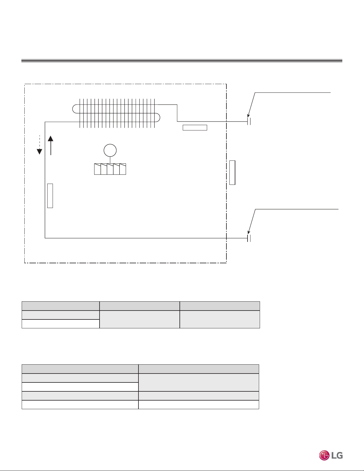
ART COOL GALLERY INDOOR UNITS
MULTI
F
MAX
MULTI
F
Figure 36: Art Cool Gallery Indoor Unit Refrigerant Flow Diagram.
Refrigerant Flow Diagram
Heating
Heat Exchanger
Turbo Fan
Cooling
Evaporator Inlet Temperature
Thermistor for
M
Thermistor for Evaporator
Outlet Temperature
Gas pipe connection port
(flare connection)
Indoor Air Temperature
Thermistor for
Liquid pipe connection port
(flare connection)
Table 17: Art Cool Gallery Indoor Unit Refrigerant Pipe Connection Port Diameters.
Model No. Vapor (inch) Liquid (inch)
LMAN097HVP
LMAN127HVP
Ø3/8 Ø1/4
Multi F and Multi F MAX Indoor Unit Engineering Manual
Table 18: Art Cool Gallery Indoor Unit Thermistor Details.
Description (Based on Cooling Mode) PCB Connector
36 | ART CO OL GALLERY™
Indoor Air Temperature Thermistor
Evaporator Inlet Temperature Thermistor
Evaporator Outlet Temperature Thermistor CN-TH2
Water Level Sensor (Optional) CN-TH3
Due to our policy of continuous product innovation, some specications may change without notication.
©LG Electronics U.S.A., Inc., Englewood Cliffs, NJ. All rights reserved. “LG” is a registered trademark of LG Corp.
CN-TH1
Page 37
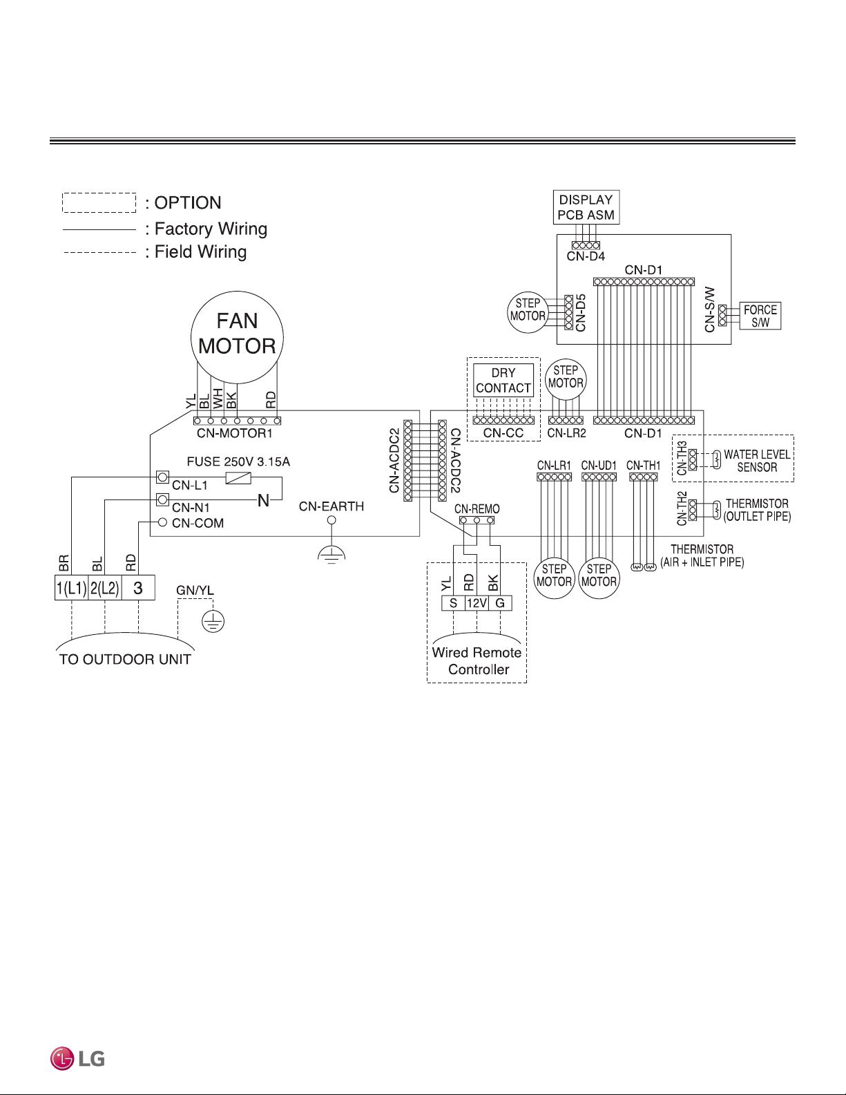
ART COOL GALLERY INDOOR UNITS
MULTI
F
MAX
MULTI
F
Figure 37: Multi F Art Cool Gallery Indoor Units Wiring Diagram.
Wiring Diagram
Art Cool Gallery™
Due to our policy of continuous product innovation, some specications may change without notication.
©LG Electronics U.S.A., Inc., Englewood Cliffs, NJ. All rights reserved. “LG” is a registered trademark of LG Corp.
ART COOL G ALLERY™ | 37
Page 38
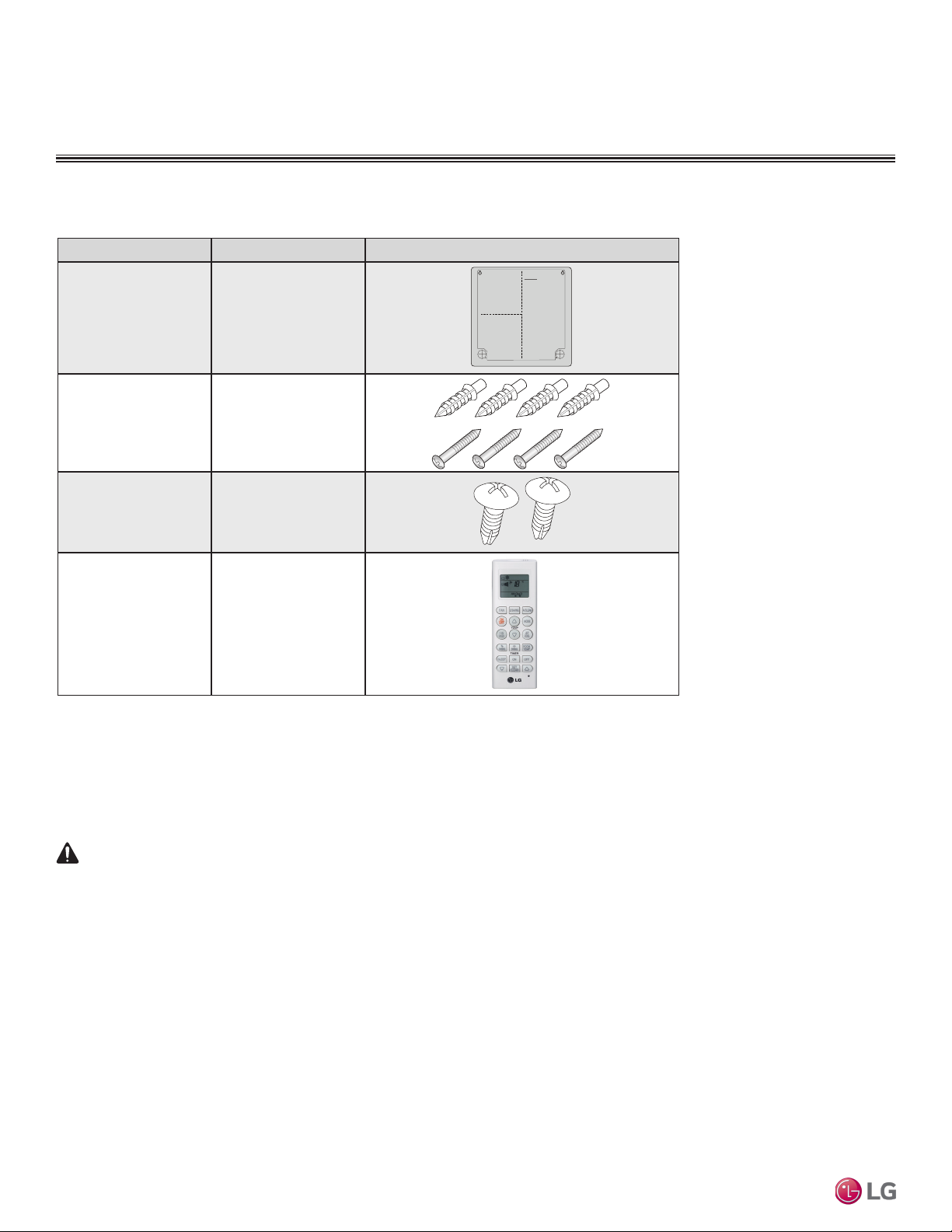
Factory Supplied Parts
WARNING
MULTI
F
MAX
MULTI
F
Table 19: Parts Table.
Part Quantity Image
Installation Guide One (1)
ART COOL GALLERY INDOOR UNITS
Factory Supplied Parts and Materials
Type “A” Screws and
Plastic Anchors
Type “B” Screws
(M4 x 12L)
Wireless Handheld
Controller with Holder
(AKB73635607)
Four (4)
Each
Two (2)
One (1)
Factory Supplied Materials
• Owner’s Manual
• Installation Manual
Required Tools
• Level
• Screwdriver
• Electric drill
• Hole core drill
• Flaring tool set
• Spanner (Half union)
• Thermometer
Installation work must be performed by trained personnel and in accordance with national wiring standards and all local or other applicable codes.
Multi F and Multi F MAX Indoor Unit Engineering Manual
Improper installation can result in re, electric shock, physical injury, or death.
Note:
Read all instructions before installing this product. Become familiar with the unit’s components and connections, and the order of installation. Incorrect
installation can degrade or prevent proper operation.
38 | ART CO OL GALL ERY™
Due to our policy of continuous product innovation, some specications may change without notication.
©LG Electronics U.S.A., Inc., Englewood Cliffs, NJ. All rights reserved. “LG” is a registered trademark of LG Corp.
Page 39

ART COOL GALLERY INDOOR UNITS
>8 inches
>20 inches
Recommended height
>5 feet from the floor
>20 inches
7/16 inch
Horizontal
Plastic Anchor
1
2
3
4
MULTI
F
MAX
MULTI
F
Installation and Best Layout Practices
Selecting the Best Location
Do’s
• Place the unit where air circulation will not be blocked.
• Place the unit where drainage can be obtained easily.
• Place the unit where noise prevention is taken into consideration.
• Ensure there is sufficient space from the ceiling and floor.
• Ensure there is sufficient maintenance space.
• Locate the indoor unit in a location where it can be easily connected to the outdoor
unit/branch distribution unit.
Don’ts
• Do not install the unit near a heat or steam source, or where considerable amounts of oil, iron powder, or flour are used.
• Do not install the unit where sulfuric acid and flammable or corrosive gases are generated, vented into, or stored.
• Do not install the unit near high-frequency generators.
• Do not install the unit near a doorway.
The unit may be damaged, may malfunction, and/ or will not operate as designed if installed in any of the conditions listed.
Installing in an Area Exposed to Unconditioned Air
In some installation applications, areas (oors, walls) in some rooms may be exposed to unconditioned air (room may be above or next to an unheated garage or storeroom). To countermeasure:
• Verify that carpet is or will be installed (carpet may increase the temperature by three degrees).
• Add insulation between the floor joists.
• Install radiant heat or another type of heating system to the floor.
Figure 38:Minimum Clearance Requirements.
Figure 39:Using the Installation Guide.
Art Cool Gallery™
Using the Installation Guide
1. Choose an appropriate location for the indoor unit. To hang the installation guide, verify that it is level
and plumb, and then tape it to the wall.
2. Drill four (4) 1/4-inch diameter holes with a depth of 1-3/16 to 1-3/8 inches for the mounting screws.
Drill one (1) two (2) inch-diameter hole for the field-installed refrigerant and drain piping.
3. Insert a plastic anchor into each of the mounting holes.
4. Screw the top two (2) screws into the wall. Do not flush them to the wall; leave a 7/16 inch space for
hanging the indoor unit.
Note:
If the unit is installed near a body of water, certain components are at risk of being corroded.
Appropriate anti-corrosion methods should be taken for the unit and all components.
Due to our policy of continuous product innovation, some specications may change without notication.
©LG Electronics U.S.A., Inc., Englewood Cliffs, NJ. All rights reserved. “LG” is a registered trademark of LG Corp.
ART COOL G ALLERY™ | 39
Page 40

ART COOL GALLERY INDOOR UNITS
Panel Connector
1A 1B
2A 2B
3
Side cover
Access Hole
for Piping
Rubber Stopper
Choose a Side
for the Drain
Connections
Field-Installed
Drain Piping
Adhesive
Drain
Hose
MULTI
F
MAX
MULTI
F
Installation and Best Layout Practices
Preparing the Indoor Unit for
Installation
Removing the Front Panel
1. First pull the top of the front panel up (1A) and then out (1B).
2. Remove the two (2) screws at the bottom (2A), then lift off the front
panel (2B).
3. To completely detach the front panel, disconnect the panel connector
found at the top of the indoor unit (3).
Removing the Piping and Side Covers
1. Unscrew the center cover.
Figure 40:Preparing for Installation.
Figure 41:Removing the Piping and Side Covers.
2. Remove the cover from the side of the indoor unit chosen for the piping connections,
and then knock out the piping access hole. If the refrigerant piping will be connected
through the back of the unit, the access hole does not need to be knocked out.
3. Remove any burrs that may have been made.
Preparing the Drain Hose
1. Remove the rubber stopper from the chosen side of the indoor unit.
Multi F and Multi F MAX Indoor Unit Engineering Manual
2. Insert the drain hose into the handle of the drain pan.
3. Connect the drain hose to the field-installed drain piping.
40 | ART COOL GALLERY™
Due to our policy of continuous product innovation, some specications may change without notication.
©LG Electronics U.S.A., Inc., Englewood Cliffs, NJ. All rights reserved. “LG” is a registered trademark of LG Corp.
Figure 42:Preparing the Drain Hose.
Page 41

ART COOL GALLERY INDOOR UNITS
Installation Guid
Drain hose
Loop
Connecting
pipe
Power wiring /
Communication
cable
Tape
Drain hose
1
2
12
MULTI
F
MAX
MULTI
F
Installation and Best Layout Practices
Preparing the Refrigerant and Drain Piping Connections
1. Depending on the installation requirements, route the indoor unit refrigerant piping and the
drain hose to the left, right (see guidelines below), or rear of the frame.
2. Bundle the piping and drain hose with tape where they meet near the indoor unit frame. Po-
sition the drain hose at the bottom of the bundle (positioning the drain hose at the top of the
bundle may cause the drain pan to overflow inside the indoor unit).
Installing Piping on the Right Side of the Indoor Unit Frame
1. Press on the top of the clamp, and then
slowly guide the piping downward.
2. Bend the piping to the right side of the
indoor unit frame.
Do not bend the piping/drain hose from side to side; it may damage the components.
Figure 44:Right Side Piping Access.
Figure 43:Preparing the Refrigerant /
Drain Connections.
Art Cool Gallery™
Hanging the Indoor Unit Frame
1. Remove the installation guide and hang the indoor unit on the top two (2) screws. Verify
the indoor unit is hanging securely on the screws.
2. Align the holes at the bottom of the indoor unit to the mounting holes. Tighten first the top
screws, then tighten the bottom screws.
3. Verify that the indoor unit is completely secured to the wall by gently shaking it up and
down.
Figure 45:Hanging the Indoor Unit Frame.
1
Holes for Hanging
(On back of
indoor unit)
2
3
Due to our policy of continuous product innovation, some specications may change without notication.
©LG Electronics U.S.A., Inc., Englewood Cliffs, NJ. All rights reserved. “LG” is a registered trademark of LG Corp.
e
Plastic Anchors
ART COOL G ALLERY™ | 41
Page 42
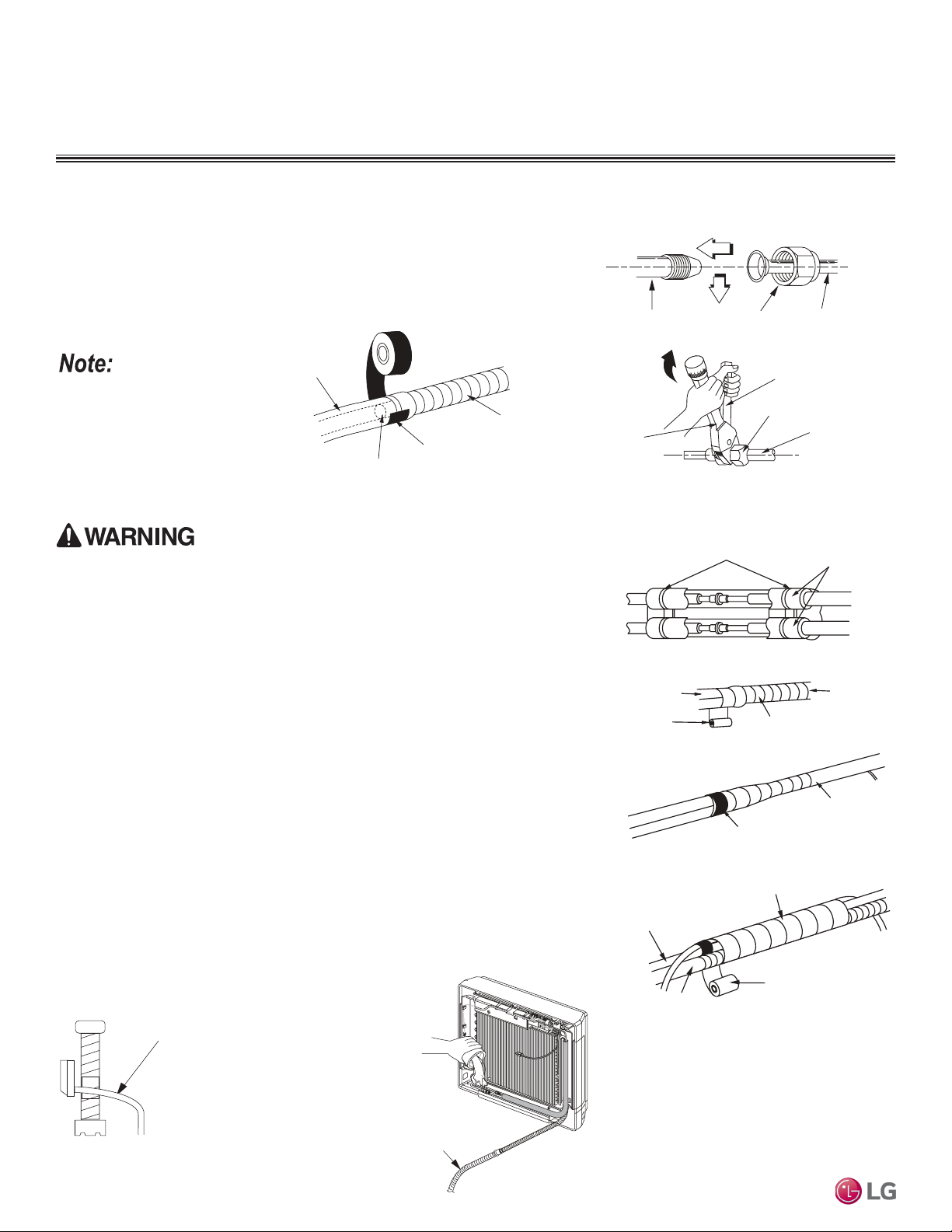
ART COOL GALLERY INDOOR UNITS
Indoor unit piping
Flare nut Field-installed
piping
Spanner
Field-installed
piping
Flare nut
Torque
wrench
Narrow tape
Adhesive
Drain extension
Indoor unit
drain hose
Bands
Insulation
Narrow tape
Field-supplied
piping
Wide tape
Wrap with tape
Indoor unit
piping
Piping
Wrap with tape
Drain hose
Piping
Wide tape
1.
2.
3.
Slope Down
Indoor Unit s
Drain extension
MULTI
F
MAX
MULTI
F
Installation and Best Layout Practices
Connecting the Indoor Unit Piping to the Field-Installed Piping
1. Center align the indoor unit piping (refrigerant and drain) and the field-installed
piping, then hand tighten the flare nut.
2. Tighten the flare nut with a torque wrench.
3. Attach the drain tube piping to the indoor unit drain hose as shown below.
Figure 47:Extending the Drain Hose.
If the drain hose is routed inside a room, add insulation
to prevent condensation from
forming.
Insulating the Refrigerant and Drain Piping
Figure 46:Indoor Unit to Field-Installed Piping Connection.
Figure 48:Insulating the Piping.
Ensure all piping is insulated. Exposed piping can cause burns if touched.
Refrigerant Piping Insulation
Field-installed vapor and liquid refrigerant piping lines must be properly and completely
covered in insulation (up to the indoor unit piping connections). Any exposed piping may
generate condensate or will cause burns if touched. Insulation for this field-installed refrigerant piping must have a minimum heat resistance of 248°F.
Drain Piping Insulation
Drain piping must have insulation a minimum of 7/32 inches thick.
Installing the Insulation
1. Overlap the insulation at the connection of the field-installed piping and the indoor unit
piping. Tape together so there are no gaps.
2. Secure insulation to the rear piping housing section with vinyl tape.
3. Bundle the piping and drain hose with tape where they meet at the back of the indoor
unit frame. Position the drain hose at the bottom of the bundle (positioning the drain
hose at the top of the bundle may cause the drain pan to overflow inside the indoor
Multi F and Multi F MAX Indoor Unit Engineering Manual
unit).
Drain Slope
Drain hose should point
down so water can flow
away easily.
Figure 49:Drain Piping Slope.
42 | ART C OOL GAL LERY™
Checking the Drainage System
1. Pour water on the in-
2. Ensure the water
door unit evaporator.
flows through and out
of the hose and away
from the indoor unit
without leaking.
Due to our policy of continuous product innovation, some specications may change without notication.
©LG Electronics U.S.A., Inc., Englewood Cliffs, NJ. All rights reserved. “LG” is a registered trademark of LG Corp.
Figure 50:Checking the Drainage
System.
Page 43

ART COOL GALLERY INDOOR UNITS
GRN / YLW
MULTI
F
MAX
MULTI
F
Installation and Best Layout Practices
Power Wiring / Communications Cable Guidelines
• Follow manufacturer’s circuit diagrams in the technical manuals.
• Confirm power source specifications.
• Confirm that the electrical capacity is sufficient.
• Starting current must be maintained ±10 percent of the rated current marked on the outdoor unit name plate.
• Confirm cable thickness specifications.
• It is recommended that a circuit breaker is installed, especially if conditions could become wet or moist.
• Include a disconnect in the power wiring system, add an air gap contact separation of at least 1/8 inch in each active (phase) conductor.
• Loose wiring may cause unit to malfunction, overheat, and catch fire, resulting in severe injury or death.
Note:
• Terminal screws may become loose during transport. Properly tighten the terminal connections during installation.
A voltage drop may cause the following problems:
• Magnetic switch vibration, fuse breaks, or disturbance to the normal function of an overload protection device.
• Compressor will not receive the proper starting current.
Art Cool Gallery™
Connecting the Power Wiring and Communications Cable
1. Insert the power wiring/communications cable from the outdoor unit or branch distribution unit (Multi F MAX systems only)
through the access hole of the indoor unit (ground wire should be
longer than the other wires/cables). Unscrew the control board
cover.
2. Connect each wire to its appropriate terminal on the indoor unit
control board. Verify that the color and terminal numbers from
the outdoor unit or branch distribution unit (Multi F MAX systems
only) wiring match the color and terminal numbers on the indoor
unit.
3. Secure the power wiring/communications cable to the control
board.
4. Reattach the control board cover.
Figure 52:Simplied View of Indoor Unit to Outdoor Unit / Branch
Distribution Unit Terminal Connections—LMAN097HVP and
LMAN127HVP models.
Outdoor Unit Terminal Block or
GND
Indoor Unit Terminal Block
BR
32(L2)1(L1)
BL
RD
Branch Distribution Unit Terminal Block
(Multi F MAX Systems Only)
3 or S
GND
Figure 51:Connecting the Power Wiring / Communications Cable.
Control Board Cover
Lock nut
(field supplied)
Conduit
(field supplied)
1(L1)2(L2) 3
Due to our policy of continuous product innovation, some specications may change without notication.
©LG Electronics U.S.A., Inc., Englewood Cliffs, NJ. All rights reserved. “LG” is a registered trademark of LG Corp.
ART COOL G ALLERY™ | 43
Page 44

ART COOL GALLERY INDOOR UNITS
MULTI
F
MAX
MULTI
F
Installation and Best Layout Practices
Controller Options
Art Cool Gallery wall-mounted indoor units include a handheld controller (AKB73635607), but optional LG-supplied wired controllers are
available.
Wireless Handheld Controller
Figure 53:AKB73635607
Wireless Controller.
Display
Screen
Control
Panel
Table 20: AKB73635607 Wireless Controller Functions.
Control
Panel
Button
Display
Screen
Description
Air circulation button1: Circulates the room air without operating in cooling
or heating mode.
Sleep Mode Auto Button1: Sets the sleep mode auto operation.
Temperature Adjustment Buttons: Raises or lowers temperature setpoint in
cooling and heating operation.
On / Off Button: Turns the power on/off.
Indoor Fan Speed Button: Changes the fan speed.
Operation mode selection button1: Selects the operation mode.
Cooling operation / Auto operation or auto changeover /
Dehumidifying operation / Heating operation
Jet Cool / Jet Heat Button1: Warms up or cools down the indoor
temperature within a short period.
Air Flow Direction Button: Adjusts the airflow direction.
Temperature Display Button: Displays the room temperature. Press and
hold button down for five (5) seconds to change from °C to °F.
Operation Mode Sequence
Cooling Mode
Multi F and Multi F MAX Indoor Unit Engineering Manual
↓
Auto Operation
↓
Dehumidification Mode
↓
Heating Mode
1
Depending on the indoor unit model, some functions may not be supported.
44 | ART CO OL GALLERY™
Due to our policy of continuous product innovation, some specications may change without notication.
©LG Electronics U.S.A., Inc., Englewood Cliffs, NJ. All rights reserved. “LG” is a registered trademark of LG Corp.
Timer button: Sets the current time and the start/end times.
Navigation/Functions Button1: Adjusts the time and sets the special functions.
Auto clean / Operates energy saving cooling / Adjusts the brightness
of the indoor unit display
Set/Clear Button: Sets or cancels functions.
Reset Button: Resets the air conditioner settings.
Page 45

ART COOL GALLERY INDOOR UNITS
4 to 5 feet
above the floor
NO
NO
NO
YES
Remote Controller
TEMP
Remote Controller
TEMP
Re
m
ot
e
C
o
n
t
r
ol
l
er
TEMP
Top
Wall Wa ll
Wall Wall
Installing the Controller
Removing the Controller
Indoor Unit Terminal Block
GRN / YLW
(Multi F MAX Systems Only)
MULTI
F
MAX
MULTI
F
Wired Controller Connections
Figure 54:Wired Controller Connection on the Indoor Unit Terminal Block.
GND
Installation and Best Layout Practices
1(L1 )2(L2)
BR
BL
3
RD
To Outdoor Unit or Branch Distribution Unit
CN-REMO
To Wired Controller
Wired Controller Placement
Wired controllers include a sensor to detect room temperature. To maintain comfort
levels in the conditioned space, the wired controller must be installed in a location
away from direct sunlight, high humidity, and where it could be directly exposed to
cold air. Controller must be installed four (4) to five (5) feet above the floor where its
LED display can be read easily, in an area with good air circulation, and where it can
detect an average room temperature.
Do not install the wired controller near or in:
• Drafts or dead spots behind doors and in corners
• Hot or cold air from ducts
• Radiant heat from the sun or appliances
• Concealed pipes and chimneys
• An area where temperatures are uncontrolled, such as an outside wall
Hanging the Wired Controller
1. The controller wiring/cable can be installed in one of three direc-
tions: top, back, or on the right side. If top or right side installation
is desired, remove cable guide grooves on the controller, and
then position wiring/cable on applicable side.
2. Choose and mark the area of installation, and then screw the wall
plate into place (using the provided parts). Install the controller
wall plate to fit the electrical box if one is present. Ensure that no
gaps exist between the wall plate and the wall itself.
3. Arrange wiring/cables so as not to interfere with the controller
circuitry. Position the wired controller on the wall plate. Snap into
place by pressing the bottom part of the wired controller onto
the wall plate. Make sure that no gaps exist between the wired
controller and the wall plate on all sides.
4. To remove wired controller from the wall plate, insert a screwdriver into the two holes at the bottom. Twist screwdriver to
release controller. Do not damage the controller components
when removing.
Figure 55:Proper Location for the Wired Controller.
Figure 56:Removing the Cable Guide Grooves.
Top
Back
Figure 57:Attaching the Wall Plate.
Right
Side
Figure 58:Installing/Removing the
Controller.
Right
Side
Art Cool Gallery™
Due to our policy of continuous product innovation, some specications may change without notication.
©LG Electronics U.S.A., Inc., Englewood Cliffs, NJ. All rights reserved. “LG” is a registered trademark of LG Corp.
ART COOL G ALLERY™ | 45
Page 46

12
34
ART COOL GALLERY INDOOR UNITS
MULTI
F
MAX
MULTI
F
Installation and Best Layout Practices
Assigning the Thermistor for Temperature Detection
Each indoor unit includes a return air thermistor assigned to sense the temperature. If a wired controller is installed, there is a choice of
sensing temperature with either the indoor unit return air thermistor or the thermistor in the wired controller. It is also an option to set both
thermistors to sense temperature so that indoor unit bases its operation on the first thermistor to reach the designated temperature differential. For applicable indoor units, an optional Remote Temperature Sensor can be used in lieu of the return air thermistor—either alone or in
conjunction with a wired controller thermistor as previously described.
Finalizing Indoor Unit Installation
1. Verify that the side covers are closed or opened, depending on
installation requirements. Place the power wiring / communications cable in the bottom groove along the left side of the frame.
2. Reconnect the panel connector found at the top of the indoor unit.
3. Attach the top part of the front panel, then position its tabs in the
grooves on the bottom part of the indoor unit frame.
4. To ensure the front panel tabs are securely positioned in the
grooves, adjust the panel by loosening or tightening the screws
at the bottom.
Figure 59:Final Installation Step—Reattaching the Front Panel.
Front Panel
Connector
Multi F and Multi F MAX Indoor Unit Engineering Manual
46 | ART CO OL GALL ERY™
Due to our policy of continuous product innovation, some specications may change without notication.
©LG Electronics U.S.A., Inc., Englewood Cliffs, NJ. All rights reserved. “LG” is a registered trademark of LG Corp.
Page 47

Art Cool Gallery™
MULTI
F
MAX
MULTI
F
Due to our policy of continuous product innovation, some specications may change without notication.
©LG Electronics U.S.A., Inc., Englewood Cliffs, NJ. All rights reserved. “LG” is a registered trademark of LG Corp.
ART COOL G ALLERY™ | 47
Page 48

STANDARD
WALL-MOUNTED
INDOOR UNIT DATA
“Mechanical Specifications” on page 49
“General Data / Specifications” on page 50
“Dimensions” on page 51
“Cooling Capacity Table” on page 53
“Heating Capacity Table” on page 56
“Acoustic Data” on page 58
“Air Velocity and Temperature Distribution” on page 60
“Refrigerant Flow Diagram” on page 62
“Wiring Diagram” on page 63
“Factory Supplied Parts and Materials” on page 65
“Installation and Best Layout Practices” on page 66
Page 49

MULTI
F
MAX
MULTI
F
STANDARD WALL-MOUNTED INDOOR UNITS
Mechanical Specications and Features
Standard Wall-Mounted Indoor Units
General
All LG indoor units are factory assembled, wired, piped, and pro-
vided with a control circuit board, fan, and motor. Standard Wall-
Mounted units have a sound rating no higher than 46 dB(A) as tested
per KSA0701 ISO Standard 3745.
Coil
Indoor unit coils are comprised of a minimum of two rows of
aluminum fins mechanically bonded to copper tubing. The coils are
pressure tested at the factory. Each unit is provided with a factory
installed condensate drain pan below the coil.
Refrigerant System
The system is designed for use with R410A refrigerant. The refrigeration circuit is pressure-tested at the factory and shipped with a
holding charge of helium gas. Refrigerant pipe connections are 45°
flare. All refrigerant lines from the outdoor unit to the indoor units
must be field insulated.
Electrical
The indoor units require 208–230Vac/60Hz/1Φ power with voltage
variance of no more than ±10%.
Casing
The units mount on a vertical surface. They are shipped with a separate back plate that secures the unit to the wall, protruding no more
than nine (9) inches. Refrigerant piping can be installed in one (1) of
four (4) different directions.
Finish
The Standard Wall-Mounted unit has a curved architectural panel
with a pearl white finish. Unit casing has a pearl white or dark gray
finish and is manufactured of heavy-duty acrylonitrile butadiene
styrene (ABS) and high impact polystyrene (HIPS) plastic.
Fan Assembly and Control
The unit has a single, direct-drive, crossow fan made of high strength
ABS plastic. The fan motor is brushless digitally controlled (BLDC)
with permanently lubricated and sealed ball bearings. The fan / motor
assembly is mounted on vibration attenuating rubber grommets. Fan
speed is controlled using a microprocessor-based direct digitally
controlled algorithm that provides pre-programmed, eld-selectable
xed or auto fan speeds in the Heating and Cooling modes. For
Standard Wall-Mounted units, the indoor fan has Low, Med, High, Jet
Cool, and Auto settings for Cooling mode; and has Low, Med, High,
Jet Heat, and Auto settings for Heating mode. The Auto setting adjusts
the fan speed based on the difference between the controller setpoint
and space temperature. Also, the separate Chaos setting provides a
simultaneous and random change in fan speed and ow direction at
the discharge, simulating a natural outdoor breeze.
Features
• Inverter (Variable speed fan)
• Comfort Air
• 3M filter
• Jet cool/Jet Heat
Figure 60: Multi F Standard Wall-Mounted Indoor Unit.
Air Filter
The return air inlet has a factory-supplied primary removable, washable filter. The unit is also equipped with a secondary 3M Micro Dust
filter. Filters are accessed from the front of the unit without the use
of tools.
Airflow Guide Vanes
A factory-installed motorized guide vane controls the direction of
airflow from side to side. A motorized louver provides an automatic
change in airflow by directing the air up and down for uniform air
distribution.
Microprocessor Control
The indoor unit has an integrated control panel to communicate with
the outdoor unit. All unit operation parameters are stored in non-volatile memory resident on the unit microprocessor. The microprocessor
controls space temperature through using the value provided by the
temperature sensor within the indoor unit. The microprocessor control
will activate indoor unit operation when the indoor room temperature
falls below or rises above a setpoint temperature, at which point, a
signal is sent to the outdoor unit to begin the appropriate mode. The
microprocessor also provides self-diagnostics and auto restart func-
tions. A eld-supplied four-wire power / communications cable must
be installed to connect the indoor unit(s) to the outdoor unit.
Controls
The indoor unit casing has a factory-standard, integral infrared sensor to communicate with the supplied LG wireless handheld remote
controller. An optional LG supplied wired controller is available as
an additional accessory. Communication between the indoor units
and the outdoor unit is accomplished through 18 AWG, four-core,
stranded and shielded power / communication cable. The indoor unit
has built-in wi-fi and can be controlled with LG’s SmartThinQ app on
a smart device. A field-supplied wi-fi network and smart device are
required. The SmartThinQ app is free and is available for Android
and iOS smart devices.
Condensate
The unit is designed for gravity draining of condensate and includes
a flexible drain hose capable of installation in one of two directions.
The unit also includes a connection that is compatible with the AquaGuard® AG-9300-LG condensate sensor.
• Group control
• Self-cleaning indoor coil
• Auto operation
• Auto restart operation
Due to our policy of continuous product innovation, some specications may change without notication.
©LG Electronics U.S.A., Inc., Englewood Cliffs, NJ. All rights reserved. “LG” is a registered trademark of LG Corp.
• Built-in wi-fi
• Dehumidifying function
• Self-diagnostic function
• Wireless LCD remote control included
Standard Wall-Mounted
STD. WALL-MOUNTED | 49
Page 50

MULTI
F
MAX
MULTI
F
STANDARD WALL-MOUNTED INDOOR UNITS
General Data / Specications
Table 21: Multi F Standard Wall-Mounted Indoor Unit General Data.
Model Name LMN079HVT LSN090HSV5 LSN120HSV5 LMN159HVT LSN180HSV5 LMN249HVT
Nominal Cooling Capacity (Btu/h)
Nominal Heating Capacity (Btu/h)
1
1
Operating Range
Cooling (°F WB)
Heating (°F DB)
Fan
Type
Motor Output (W) x Qty.
Motor/Drive
Airflow Rate CFM (H/M/L)
Unit Data
Refrigerant Type
2
Refrigerant Control
Power Supply V, Ø, Hz3
Rated Amps (A)
Sound Pressure Level ±3 dB(A)
(H/M/L)4
Dimensions (W x H x D, in.)
Net Unit Weight (lbs.)
Shipping Weight (lbs.)
Power Wiring / Communications
Cable (No. x AWG)5
Heat Exchanger (Row x Column x
Fin / inch) x Number
Pipe Size
Liquid (in.)
Vapor (in.)
Connection Size
Multi F and Multi F MAX Indoor Unit Engineering Manual
Liquid (in.)
Vapor (in.)
Drain O.D. / I.D. (in.)
1
Nominal capacity is rated 0 ft. above sea level with corresponding refrigerant piping length in
accordance with standard length of each outdoor unit and a 0 ft. level difference between outdoor and
indoor units. All capacities are net with a combination ratio between 95 – 105%.
Nominal cooling capacity rating obtained with air entering the indoor unit at 80ºF dry bulb (DB) and 67ºF
wet bulb (WB) and outdoor ambient conditions of 95ºF dry bulb (DB) and 75ºF wet bulb (WB).
Nominal heating capacity rating obtained with air entering the indoor unit at 70ºF dry bulb (DB) and 60ºF
wet bulb (WB) and outdoor ambient conditions of 47ºF dry bulb (DB) and 43ºF wet bulb (WB).
2
This unit comes with a dry helium charge.
7,000 9,000 12,000 14,300 18,000 24,000
8,100 10,900 13,600 15,600 21,600 25,600
57-77
59-81
Cross Flow
30 x 1 60 x 1
Brushless Digitally Controlled / Direct
254 / 204 / 148 268 / 218 / 169 282 / 233 / 177 314 / 268 / 184 558 / 438 / 353 597 / 452 / 367
R410A
EEV
208-230, 1, 60
0.4
35 / 31 / 26 36 / 32 / 27 38 / 34 / 29 42 / 38 / 32 44 / 38 / 34 46 / 41 / 36
32-15/16 x
12-1/8 x 7-7/16
18.3 25.6
23.4 32.2
4 x 18
(2 x 23 x 22) x 1 (2 x 16 x 20) x 1
1/4
3/8 1/2
1/4 3/8 1/4
3/8 5/8 1/2
27/32, 5/8
3
Acceptable operating voltage: 187V-253V.
4
Sound pressure levels are tested in an anechoic chamber under ISO Standard 3745 and are the
same in both cooling and heating mode. These values can increase due to ambient conditions during
operation.
5
All power wiring / communications cable to the IDUs be minimum 18 AWG, 4-conductor, stranded,
shielded or unshielded (if shielded, must be grounded to chassis at ODU only) and must comply with
applicable local and national codes.
39-9/32 x
13-19/32 x 8-9/32
50 | STD. WALL-MOUNTED
Due to our policy of continuous product innovation, some specications may change without notication.
©LG Electronics U.S.A., Inc., Englewood Cliffs, NJ. All rights reserved. “LG” is a registered trademark of LG Corp.
Page 51

MULTI
F
MAX
MULTI
F
STANDARD WALL-MOUNTED INDOOR UNITS
Figure 61: LMN079HVT, LSN090HSV5, LSN120HSV5, and LMN159HVT Dimensions.
Refrigerant,
Drain Pipe
and Cable
Routing
Knock Out
1/8 (3) x 1/4 (6)
1/4 (6) x 1/8 (3)
1-1/4 (31)
2-7/16 (61.5)
5-31/32 (152)
1-3/32 (50.2)
2 (51)
1-1/16 (26.2)
Hole
2-7/32 (56)
Dimensions
Unit : Inch (mm)
85°
45°
15°
15°
5/8 (15.3)
55°
55°
1-9/32 (32.7)
(61)
2-13/32
* If airflow direction control is available,
Cooling Heating
1-27/32(47)
1-1/2 (38)
Up & Down Left & Right
Connection
Decoration Cover
3-5/8 (92)
2-3/8 (60)
2-5/16
(59)
Communication
Refrigerant, Drain
Pipe and Cable
Routing Knock Out Hole
Approx. 8-19/32 (218) to liquid pipe
Approx. 11-11/32 (288) to gas pipe
Drain Hose
1-7/16 (33.5)
Terminal Block for
Power Supply and
2 (51)
2-7/32 (56)
Air Outlet Hole
Air Outlet Hole
[28-5/32 (715)]
Bottom
Air Outlet
5/16 (8)
11/32 (9)
2-7/32(56)
5-31/32 (152)
3-27/32 (98)
Display & Remote
Controller Signal
Receiver
12-1/8 (308)
Refrigerant,
Drain Pipe
and Cable
Routing
Knock Out
Hole
10-11/32 (263)
5-19/32 (142)
Ø2-9/16 (65)
Air Intake
2-17/32 (64)
32-15/16 (837)
7-7/16 (189)
3-21/32 (93)
[5-29/32 (150)]
Air Intake Hole
Left
Right
Rear
Air Intake Hole
30-3/16 (767)
Rear
Standard Wall-Mounted
Connecting Gas/Liquid Pipe
Unit Outline
5-3/16 (132)
12-1/8 (308)
Due to our policy of continuous product innovation, some specications may change without notication.
©LG Electronics U.S.A., Inc., Englewood Cliffs, NJ. All rights reserved. “LG” is a registered trademark of LG Corp.
29/32 (23)
Fixing the Installation Plate, Drilling Hole
Unit Outline
32-15/16 (837)
In Case of Left Side Piping
29/32 (23)
5-9/32 (134)
7-5/8 (194)
Installation Plate
7-27/32 (199)
7-27/32 (199)
Ø2-9/16 (65)
12-1/8 (308)
12-1/16 (306)
32-15/16 (837)
2-15/32
(63)
3-11/16 (94)
2-15/32 (63)
STD. WALL-MOUNTED | 51
Page 52

MULTI
F
MAX
MULTI
F
STANDARD WALL-MOUNTED INDOOR UNITS
Dimensions
Figure 62: LSN180HSV5 and LMN249HVT Dimensions.
Refrigerant,
Drain Pipe
and Cable
Routing
Knock Out
1/8 (3) x 1/4 (6)
1/4 (6) x 1/8 (3)
1-1/4 (31)
2-7/16 (61.5)
5-31/32 (152)
1-3/32 (50.2)
1-1/16 (26.2)
Hole
2-3/8 (60)
2-3/8 (60)
Unit : Inch (mm)
85°
45°
20°
15°
50°
50°
5/8 (15.3)
Cooling Heating
Up & Down Left & Right
2-15/32 (63)
1-15/32 (37)
1-9/32 (32.7)
(61)
2-13/32
If airflow direction control is available,*
Decoration Cover
3-17/32 (90)
2-1/4 (57)
2-7/32 (56)
Power Supply and
Communication
Refrigerant, Drain
Pipe and Cable
Routing Knock Out
Hole
Approx. 6-5/16 (160) to liquid pipe
Approx. 9-7/16 (240) to gas pipe
Connection
Drain Hose
1-7/16 (33.5)
Terminal Block for
[2-29/32 (74)]
Air Outlet Hole
[34-11/32 (872)]
Air Outlet Hole
Bottom
Air
Outlet
2-3/8 (60)
7/16 (11)
7/16(11)
2-3/8 (60)
5-9/32 (134)
3-9/32 (83)
Display & Remote
Controller Signal
Receiver
13-19/32 (345)
Refrigerant,
Drain Pipe
and Cable
Routing
Knock Out
Hole
11-13/16 (300)
5-29/32 (150)5-29/32 (150)
Ø2-9/16 (65)
Multi F and Multi F MAX Indoor Unit Engineering Manual
39-9/32 (998)
Air Intake
8-9/32 (210)
2-3/32 (53)
4-17/32 (115)
[6-11/16 (170)]
Air Intake Hole
Left
Right
Rear
[36-5/32 (918)]
Air Intake Hole
Rear
52 | STD. WALL-MOUNTED
1-1/16 (27)
Installation Plate
Fixing the Installation Plate, Drilling Hole
Connecting Gas/Liquid Pipe
39-9/32 (998)
Unit Outline
In case of Left Side Piping
6-15/32 (164)
13-19/32 (345)
Due to our policy of continuous product innovation, some specications may change without notication.
©LG Electronics U.S.A., Inc., Englewood Cliffs, NJ. All rights reserved. “LG” is a registered trademark of LG Corp.
Unit Outline
1-1/16 (27)
3-9/32 (83)
5-29/32 (150)
7-13/32 (188)7-13/32 (188)
Ø2-9/16 (65)
13-19/32 (345)
14-11/16 (373)
2-23/32 (69)
5-13/32 (137)
2-3/32 (53)
39-9/32 (998)
Page 53

MULTI
F
MAX
MULTI
F
STANDARD WALL-MOUNTED INDOOR UNITS
Cooling Capacity Table
Table 22: Multi F Standard Wall-Mounted Indoor Units Cooling Capacity Table.
Model No. /
Nominal Capacity
of Indoor Unit
(Btu/h)
LMN079HVT
7,000
LSN090HSV5
9,000
TC = Total Capacity (kBtu/h).
SHC: Sensible Heat Capacity (kBtu/h).
Nominal capacity as rated 0 ft. above sea level and a 0 ft. level difference between outdoor and indoor units. Corresponding refrigerant piping length is accordance with standard length of each outdoor unit.
Nominal cooling capacity rating obtained with air entering the indoor unit at 80ºF dry bulb (DB) and 67ºF wet bulb (WB), and outdoor ambient conditions of 95ºF dry bulb (DB) and 75ºF wet bulb (WB).
The shaded table columns and rows indicate reference data. When operating at this temperature, these values can be different if the system is not running consistently.
Outdoor Air
Temp.
(°F DB)
14 6.86 4.68 7.29 4.95 7.71 4.79 8.02 4.89 8.57 4.93 8.99 5.03
20 6.86 4.72 7.28 4.99 7.71 4.83 8.02 4.93 8.56 4.97 8.99 5.06
25 6.85 4.76 7.28 5.02 7.70 4.86 8.01 4.97 8.55 5.01 8.98 5.10
30 6.85 4.79 7.27 5.06 7.70 4.90 8.00 5.01 8.55 5.05 8.97 5.14
35 6.84 4.83 7.27 5.10 7.69 4.94 8.00 5.04 8.54 5.09 8.97 5.18
40 6.84 4.87 7.26 5.14 7.68 4.98 7.99 5.08 8.53 5.12 8.96 5.22
45 6.83 4.90 7.25 5.18 7.68 5.01 7.99 5.12 8.53 5.16 8.95 5.26
50 6.83 4.94 7.25 5.22 7.67 5.05 7.98 5.16 8.52 5.20 8.94 5.30
55 6.82 4.97 7.24 5.25 7.67 5.09 7.97 5.19 8.51 5.24 8.94 5.34
60 6.81 5.01 7.24 5.29 7.66 5.12 7.97 5.23 8.51 5.28 8.93 5.38
65 6.81 5.05 7.23 5.33 7.66 5.16 7.96 5.27 8.50 5.31 8.92 5.42
70 6.80 5.08 7.23 5.37 7.65 5.20 7.95 5.31 8.49 5.35 8.92 5.45
75 6.64 5.00 7.06 5.29 7.48 5.13 7.79 5.24 8.33 5.29 8.75 5.39
80 6.48 4.91 6.90 5.20 7.32 5.05 7.62 5.16 8.16 5.22 8.58 5.33
85 6.31 4.82 6.73 5.12 7.15 4.97 7.46 5.09 7.99 5.15 8.41 5.26
90 6.15 4.73 6.57 5.03 6.99 4.89 7.29 5.01 7.83 5.08 8.24 5.19
95 5.98 4.68 6.39 4.98 6.81 4.85 7.00 4.90 7.64 5.05 8.06 5.17
100 5.83 4.56 6.25 4.86 6.66 4.74 6.91 4.82 7.50 4.94 7.91 5.06
105 5.69 4.43 6.10 4.73 6.52 4.62 6.82 4.75 7.35 4.83 7.77 4.96
110 5.54 4.28 5.96 4.58 6.37 4.48 6.67 4.61 7.21 4.70 7.62 4.82
115 5.39 4.15 5.81 4.45 6.23 4.36 6.53 4.49 7.06 4.58 7.48 4.71
118 5.31 4.12 5.72 4.42 6.14 4.34 6.44 4.47 6.97 4.57 7.39 4.70
122 5.28 4.11 5.69 4.41 6.11 4.33 6.41 4.46 6.94 4.56 7.36 4.70
14 8.82 6.04 9.37 6.38 9.92 6.18 10.31 6.31 11.01 6.36 11.56 6.48
20 8.82 6.09 9.36 6.43 9.91 6.23 10.31 6.36 11.01 6.41 11.55 6.53
25 8.81 6.13 9.36 6.48 9.90 6.27 10.30 6.41 11.00 6.46 11.54 6.58
30 8.80 6.18 9.35 6.53 9.90 6.32 10.29 6.46 10.99 6.51 11.54 6.63
35 8.80 6.23 9.34 6.58 9.89 6.37 10.28 6.50 10.98 6.56 11.53 6.68
40 8.79 6.28 9.33 6.63 9.88 6.42 10.27 6.55 10.97 6.61 11.52 6.73
45 8.78 6.32 9.33 6.68 9.87 6.47 10.27 6.60 10.96 6.66 11.51 6.78
50 8.78 6.37 9.32 6.73 9.87 6.51 10.26 6.65 10.96 6.71 11.50 6.83
55 8.77 6.42 9.31 6.78 9.86 6.56 10.25 6.70 10.95 6.76 11.49 6.88
60 8.76 6.46 9.31 6.83 9.85 6.61 10.24 6.75 10.94 6.81 11.48 6.93
65 8.76 6.51 9.30 6.88 9.84 6.66 10.24 6.80 10.93 6.85 11.47 6.98
70 8.75 6.56 9.29 6.92 9.84 6.70 10.23 6.85 10.92 6.90 11.47 7.03
75 8.54 6.45 9.08 6.82 9.62 6.61 10.01 6.75 10.71 6.82 11.25 6.96
80 8.33 6.34 8.87 6.71 9.41 6.51 9.80 6.66 10.49 6.73 11.03 6.87
85 8.12 6.22 8.66 6.60 9.20 6.41 9.59 6.56 10.28 6.64 10.82 6.79
90 7.91 6.10 8.45 6.48 8.99 6.31 9.37 6.46 10.06 6.55 10.60 6.70
95 7.68 6.04 8.22 6.43 8.75 6.26 9.00 6.32 9.83 6.52 10.36 6.67
100 7.50 5.88 8.03 6.26 8.57 6.11 8.88 6.22 9.64 6.37 10.17 6.53
105 7.31 5.72 7.84 6.10 8.38 5.96 8.77 6.12 9.45 6.23 9.99 6.39
110 7.12 5.52 7.66 5.90 8.19 5.78 8.58 5.94 9.26 6.06 9.80 6.22
115 6.94 5.36 7.47 5.74 8.01 5.63 8.39 5.79 9.08 5.91 9.61 6.08
118 6.82 5.32 7.36 5.70 7.89 5.60 8.28 5.76 8.96 5.89 9.50 6.06
122 6.79 5.30 7.32 5.69 7.86 5.59 8.24 5.76 8.93 5.89 9.46 6.06
68 / 57 73 / 61 77 / 64 80 / 67 86 / 72 90 / 75
TC SHC TC SHC TC SHC TC SHC TC SHC TC SHC
Indoor Air Temp. °F DB / °F WB
Standard Wall-Mounted
Due to our policy of continuous product innovation, some specications may change without notication.
©LG Electronics U.S.A., Inc., Englewood Cliffs, NJ. All rights reserved. “LG” is a registered trademark of LG Corp.
STD. WALL-MOUNTED | 53
Page 54

MULTI
F
MAX
MULTI
F
STANDARD WALL-MOUNTED INDOOR UNITS
Cooling Capacity Table
Table 23: Multi F Standard Wall-Mounted Indoor Units Cooling Capacity Table (continued).
Model No. /
Nominal Capacity
of Indoor Unit
(Btu/h)
LSN120HSV5
12,000
LMN159HVT
14,300
Multi F and Multi F MAX Indoor Unit Engineering Manual
TC = Total Capacity (kBtu/h).
SHC: Sensible Heat Capacity (kBtu/h).
Nominal capacity as rated 0 ft. above sea level and a 0 ft. level difference between outdoor and indoor units. Corresponding refrigerant piping length is accordance with standard length of each outdoor unit.
Nominal cooling capacity rating obtained with air entering the indoor unit at 80ºF dry bulb (DB) and 67ºF wet bulb (WB), and outdoor ambient conditions of 95ºF dry bulb (DB) and 75ºF wet bulb (WB).
The shaded table columns and rows indicate reference data. When operating at this temperature, these values can be different if the system is not running consistently.
Outdoor Air
Temp.
(°F DB)
14 11.76 8.51 12.49 8.99 13.22 8.70 13.75 8.88 14.69 8.96 15.42 9.13
20 11.75 8.57 12.48 9.06 13.21 8.77 13.74 8.95 14.67 9.03 15.40 9.20
25 11.75 8.64 12.48 9.13 13.20 8.84 13.73 9.02 14.66 9.10 15.39 9.27
30 11.74 8.71 12.47 9.20 13.19 8.90 13.72 9.09 14.65 9.17 15.38 9.34
35 11.73 8.77 12.46 9.27 13.18 8.97 13.71 9.16 14.64 9.24 15.37 9.41
40 11.72 8.84 12.45 9.34 13.17 9.04 13.70 9.23 14.63 9.31 15.36 9.48
45 11.71 8.90 12.44 9.41 13.16 9.11 13.69 9.30 14.62 9.38 15.35 9.55
50 11.70 8.97 12.43 9.47 13.15 9.17 13.68 9.37 14.61 9.45 15.33 9.62
55 11.69 9.03 12.42 9.54 13.14 9.24 13.67 9.44 14.60 9.52 15.32 9.70
60 11.68 9.10 12.41 9.61 13.13 9.31 13.66 9.50 14.59 9.58 15.31 9.77
65 11.67 9.17 12.40 9.68 13.12 9.38 13.65 9.57 14.57 9.65 15.30 9.84
70 11.66 9.23 12.39 9.75 13.11 9.44 13.64 9.64 14.56 9.72 15.29 9.91
75 11.38 9.08 12.11 9.60 12.83 9.31 13.35 9.51 14.27 9.60 15.00 9.79
80 11.10 8.92 11.82 9.45 12.55 9.17 13.07 9.38 13.99 9.48 14.71 9.68
85 10.83 8.76 11.54 9.29 12.26 9.03 12.78 9.24 13.70 9.36 14.42 9.56
90 10.55 8.60 11.26 9.13 11.98 8.88 12.50 9.10 13.42 9.22 14.13 9.43
95 10.25 8.51 10.96 9.05 11.67 8.82 12.00 8.90 13.10 9.18 13.81 9.39
100 10.00 8.28 10.71 8.82 11.42 8.61 11.84 8.76 12.85 8.98 13.56 9.20
105 9.75 8.05 10.46 8.59 11.17 8.40 11.69 8.62 12.60 8.78 13.31 9.01
110 9.50 7.77 10.21 8.31 10.92 8.14 11.44 8.37 12.35 8.53 13.07 8.76
115 9.25 7.54 9.96 8.08 10.67 7.92 11.19 8.15 12.10 8.33 12.82 8.56
118 9.10 7.49 9.81 8.03 10.52 7.88 11.04 8.12 11.95 8.30 12.67 8.54
122 9.05 7.47 9.76 8.01 10.48 7.87 10.99 8.11 11.90 8.29 12.62 8.53
14 14.02 10.23 14.89 10.80 15.76 10.46 16.39 10.68 17.50 10.77 18.37 10.97
20 14.01 10.31 14.88 10.89 15.75 10.54 16.38 10.76 17.49 10.85 18.36 11.06
25 14.00 10.39 14.87 10.97 15.74 10.62 16.36 10.85 17.47 10.94 18.34 11.15
30 13.99 10.47 14.85 11.06 15.72 10.70 16.35 10.93 17.46 11.02 18.33 11.23
35 13.98 10.55 14.84 11.14 15.71 10.79 16.34 11.01 17.45 11.11 18.32 11.32
40 13.96 10.62 14.83 11.22 15.70 10.87 16.33 11.10 17.43 11.19 18.30 11.40
45 13.95 10.70 14.82 11.31 15.69 10.95 16.31 11.18 17.42 11.27 18.29 11.49
50 13.94 10.78 14.81 11.39 15.68 11.03 16.30 11.26 17.41 11.36 18.27 11.57
55 13.93 10.86 14.80 11.47 15.66 11 .11 16.29 11.34 17.39 11.44 18.26 11.66
60 13.92 10.94 14.79 11.56 15.65 11.19 16.28 11.43 17.38 11.52 18.25 11.74
65 13.91 11.02 14.78 11.64 15.64 11.27 16.26 11.51 17.37 11.61 18.23 11.83
70 13.90 11.10 14.76 11.72 15.63 11.35 16.25 11.59 17.35 11.69 18.22 11.91
75 13.57 10.92 14.43 11.55 15.29 11.19 15.91 11.44 17.01 11.55 17.87 11.78
80 13.23 10.73 14.09 11.36 14.95 11.03 15.57 11.28 16.67 11.40 17.53 11.64
85 12.90 10.53 13.76 11.17 14.61 10.86 15.23 11.11 16.33 11.25 17.18 11.49
90 12.57 10.33 13.42 10.98 14.28 10.68 14.90 10.94 15.99 11.09 16.84 11.34
95 12.21 10.23 13.06 10.88 13.91 10.60 14.30 10.70 15.61 11.03 16.46 11.29
100 11.91 9.95 12.76 10.60 13.61 10.35 14.11 10.53 15.31 10.79 16.16 11.06
105 11.61 9.68 12.46 10.33 13.32 10.09 13.93 10.37 15.02 10.56 15.87 10.83
110 11.32 9.35 12.17 10.00 13.02 9.78 13.63 10.06 14.72 10.26 15.57 10.53
115 11.02 9.07 11.87 9.71 12.72 9.52 13.33 9.80 14.42 10.01 15.27 10.29
118 10.84 9.00 11.69 9.66 12.54 9.48 13.16 9.76 14.24 9.98 15.09 10.26
122 10.78 8.98 11.63 9.64 12.48 9.46 13.10 9.74 14.18 9.97 15.03 10.25
68 / 57 73 / 61 77 / 64 80 / 67 86 / 72 90 / 75
TC SHC TC SHC TC SHC TC SHC TC SHC TC SHC
Indoor Air Temp. °F DB / °F WB
54 | STD. WALL-MOUNTED
Due to our policy of continuous product innovation, some specications may change without notication.
©LG Electronics U.S.A., Inc., Englewood Cliffs, NJ. All rights reserved. “LG” is a registered trademark of LG Corp.
Page 55

MULTI
F
MAX
MULTI
F
STANDARD WALL-MOUNTED INDOOR UNITS
Cooling Capacity Table
Table 24: Multi F Standard Wall-Mounted Indoor Units Cooling Capacity Table (continued).
Model No. /
Nominal Capacity
of Indoor Unit
(Btu/h)
LSN180HSV5
18,000
LMN249HVT
24,000
TC = Total Capacity (kBtu/h).
SHC: Sensible Heat Capacity (kBtu/h).
Nominal capacity as rated 0 ft. above sea level and a 0 ft. level difference between outdoor and indoor units. Corresponding refrigerant piping length is accordance with standard length of each outdoor unit.
Nominal cooling capacity rating obtained with air entering the indoor unit at 80ºF dry bulb (DB) and 67ºF wet bulb (WB), and outdoor ambient conditions of 95ºF dry bulb (DB) and 75ºF wet bulb (WB).
The shaded table columns and rows indicate reference data. When operating at this temperature, these values can be different if the system is not running consistently.
Outdoor Air
Temp.
(°F DB)
14 17.65 12.33 18.74 13.02 19.84 12.61 20.63 12.88 22.03 12.98 23.12 13.23
20 17.63 12.43 18.73 13.13 19.82 12.71 20.61 12.98 22.01 13.09 23.11 13.33
25 17.62 12.52 18.71 13.23 19.81 12.81 20.60 13.08 22.00 13.19 23.09 13.44
30 17.60 12.62 18.70 13.33 19.79 12.91 20.58 13.18 21.98 13.29 23.07 13.54
35 17.59 12.71 18.68 13.43 19.78 13.00 20.57 13.28 21.96 13.39 23.05 13.64
40 17.58 12.81 18.67 13.53 19.76 13.10 20.55 13.38 21.94 13.49 23.04 13.75
45 17.56 12.90 18.66 13.63 19.75 13.20 20.53 13.48 21.93 13.59 23.02 13.85
50 17.55 13.00 18.64 13.73 19.73 13.30 20.52 13.58 21.91 13.69 23.00 13.95
55 17.54 13.10 18.63 13.83 19.72 13.39 20.50 13.68 21.89 13.79 22.98 14.05
60 17.52 13.19 18.61 13.93 19.70 13.49 20.49 13.78 21.88 13.89 22.97 14.16
65 17.51 13.29 18.60 14.03 19.69 13.59 20.47 13.87 21.86 13.99 22.95 14.26
70 17.50 13.38 18.58 14.13 19.67 13.69 20.46 13.97 21.84 14.09 22.93 14.36
75 17.08 13.16 18.16 13.92 19.24 13.49 20.03 13.79 21.41 13.92 22.50 14.20
80 16.66 12.93 17.74 13.70 18.82 13.30 19.60 13.60 20.98 13.75 22.06 14.03
85 16.24 12.70 17.32 13.47 18.40 13.09 19.17 13.40 20.55 13.56 21.63 13.85
90 15.82 12.46 16.90 13.23 17.97 12.88 18.75 13.19 20.12 13.37 21.20 13.67
95 15.37 12.33 16.44 13.12 17.51 12.78 18.00 12.90 19.65 13.30 20.72 13.61
100 14.99 12.00 16.06 12.78 17.13 12.47 17.77 12.70 19.28 13.01 20.35 13.33
105 14.62 11.67 15.69 12.45 16.76 12.17 17.53 12.50 18.90 12.73 19.97 13.05
110 14.24 11.27 15.32 12.05 16.39 11.79 17.16 12.13 18.53 12.36 19.60 12.70
115 13.87 10.93 14.94 11.71 16.01 11.48 16.79 11.82 18.15 12.07 19.22 12.41
118 13.65 10.85 14.72 11.64 15.79 11.42 16.56 11.77 17.93 12.03 19.00 12.37
122 13.57 10.83 14.64 11.62 15.71 11.40 16.49 11.75 17.85 12.01 18.92 12.36
14 23.53 16.82 24.99 17.77 26.45 17.21 27.50 17.57 29.37 17.72 30.83 18.05
20 23.51 16.95 24.97 17.91 26.43 17.34 27.48 17.70 29.35 17.85 30.81 18.19
25 23.49 17.08 24.95 18.05 26.41 17.47 27.46 17.84 29.33 17.99 30.79 18.33
30 23.47 17.21 24.93 18.19 26.39 17.61 27.44 17.98 29.30 18.13 30.76 18.47
35 23.46 17.35 24.91 18.32 26.37 17.74 27.42 18.12 29.28 18.27 30.74 18.61
40 23.44 17.48 24.89 18.46 26.35 17.88 27.40 18.25 29.26 18.41 30.72 18.75
45 23.42 17.61 24.87 18.60 26.33 18.01 27.38 18.39 29.24 18.54 30.69 18.89
50 23.40 17.74 24.85 18.74 26.31 18.14 27.36 18.52 29.21 18.68 30.67 19.03
55 23.38 17.87 24.84 18.87 26.29 18.27 27.34 18.66 29.19 18.82 30.64 19.17
60 23.37 18.00 24.82 19.01 26.27 18.41 27.32 18.79 29.17 18.95 30.62 19.31
65 23.35 18.13 24.80 19.15 26.25 18.54 27.29 18.93 29.15 19.09 30.60 19.45
70 23.33 18.26 24.78 19.28 26.23 18.67 27.27 19.07 29.13 19.23 30.57 19.59
75 22.77 17.95 24.21 18.99 25.66 18.41 26.70 18.81 28.55 18.99 29.99 19.37
80 22.21 17.65 23.65 18.69 25.09 18.14 26.13 18.55 27.97 18.75 29.42 19.14
85 21.65 17.33 23.09 18.38 24.53 17.86 25.57 18.28 27.40 18.50 28.84 18.90
90 21.09 17.00 22.53 18.06 23.96 17.57 25.00 18.00 26.83 18.24 28.27 18.65
95 20.49 16.82 21.92 17.89 23.35 17.44 24.00 17.60 26.20 18.14 27.63 18.57
100 19.99 16.37 21.42 17.44 22.85 17.02 23.69 17.33 25.70 17.75 27.13 18.19
105 19.49 15.92 20.92 16.99 22.35 16.60 23.38 17.06 25.20 17.36 26.63 17.81
110 18.99 15.38 20.42 16.44 21.85 16.09 22.88 16.55 24.70 16.87 26.13 17.32
115 18.49 14.91 19.92 15.98 21.35 15.66 22.38 16.12 24.20 16.47 25.63 16.93
118 18.19 14.81 19.62 15.88 21.05 15.59 22.08 16.05 23.90 16.41 25.33 16.88
122 18.10 14.77 19.52 15.85 20.95 15.56 21.98 16.03 23.81 16.39 25.23 16.86
68 / 57 73 / 61 77 / 64 80 / 67 86 / 72 90 / 75
TC SHC TC SHC TC SHC TC SHC TC SHC TC SHC
Indoor Air Temp. °F DB / °F WB
Standard Wall-Mounted
Due to our policy of continuous product innovation, some specications may change without notication.
©LG Electronics U.S.A., Inc., Englewood Cliffs, NJ. All rights reserved. “LG” is a registered trademark of LG Corp.
STD. WALL-MOUNTED | 55
Page 56

MULTI
F
MAX
MULTI
F
STANDARD WALL-MOUNTED INDOOR UNITS
Heating Capacity Table
Table 25: Multi F Standard Wall-Mounted Indoor Units Heating Capacity Table.
Model No. /
Nominal Capacity of
Indoor Unit (Btu/h)
LMN079HVT
8,100
LSN090HSV5
10,900
LSN120HSV5
13,600
Multi F and Multi F MAX Indoor Unit Engineering Manual
TC = Total Capacity (kBtu/h).
Nominal capacity as rated 0 ft. above sea level and a 0 ft. level difference between outdoor and indoor units. Corresponding refrigerant piping length is accordance with standard length of each outdoor unit.
Nominal heating capacity rating obtained with air entering the indoor unit at 70ºF dry bulb (DB) and 60ºF wet bulb (WB), and outdoor ambient conditions of 47ºF dry bulb (DB) and 43ºF wet bulb (WB).
Outdoor Air Temp. Indoor Air Temp. °F DB
°F DB °F WB
0 -0.4 4.17 4.11 4.07 4.05 3.99 3.82
5 4.5 4.70 4.64 4.60 4.58 4.52 4.34
10 9 5.22 5.17 5.13 5.11 5.05 4.87
17 15 5.93 5.87 5.83 5.81 5.75 5.56
20 19 6.19 6.13 6.09 6.08 6.02 5.81
25 23 6.63 6.57 6.53 6.52 6.46 6.22
30 28 7.01 6.96 6.92 6.90 6.84 6.63
35 32 7.40 7.34 7.30 7.28 7.22 7.04
40 36 7.74 7.68 7.64 7.62 7.56 7.39
45 41 8.08 8.02 7.98 7.96 7.90 7.73
47 43 8.22 8.16 8.12 8.10 8.04 7.87
50 46 8.35 8.29 8.25 8.23 8.17 7.98
55 51 8.57 8.51 8.47 8.45 8.39 8.16
60 56 8.57 8.51 8.47 8.45 8.39 8.20
63 59 8.57 8.51 8.47 8.45 8.39 8.22
68 64 8.57 8.51 8.47 8.45 8.39 8.25
0 -0.4 5.61 5.53 5.48 5.45 5.37 5.14
5 4.5 6.32 6.24 6.18 6.16 6.08 5.85
10 9 7.03 6.95 6.90 6.88 6.79 6.56
17 15 7.98 7.90 7.85 7.82 7.75 7.48
20 19 8.33 8.26 8.21 8.18 8.09 7.82
25 23 8.93 8.85 8.79 8.77 8.69 8.37
30 28 9.44 9.36 9.31 9.29 9.20 8.93
35 32 9.96 9.87 9.82 9.79 9.72 9.47
40 36 10.42 10.33 10.28 10.25 10.18 9.94
45 41 10.87 10.80 10.74 10.71 10.64 10.40
47 43 11.06 10.98 10.93 10.90 10.82 10.59
50 46 11.24 11.15 11.10 11.08 10.99 10.73
55 51 11.53 11.46 11.40 11.37 11.30 10.98
60 56 11.53 11.46 11.40 11.37 11.30 11.03
63 59 11.53 11.46 11.40 11.37 11.30 11.06
68 64 11.53 11.46 11.40 11.37 11.30 11.11
0 -0.4 7.00 6.90 6.83 6.80 6.70 6.50
5 4.5 7.89 7.78 7.71 7.69 7.59 7.40
10 9 8.78 8.67 8.60 8.58 8.48 8.31
17 15 9.95 9.86 9.79 9.76 9.67 9.47
20 19 10.40 10.30 10.23 10.20 10.10 9.90
25 23 11.14 11.03 10.96 10.95 10.85 10.60
30 28 11.78 11.67 11.60 11.59 11.49 11.30
35 32 12.42 12.31 12.24 12.21 12.13 11.99
40 36 13.00 12.89 12.82 12.79 12.70 12.58
45 41 13.56 13.46 13.39 13.36 13.28 13.16
47 43 13.80 13.70 13.63 13.60 13.50 13.40
50 46 14.02 13.91 13.84 13.82 13.72 13.59
55 51 14.39 14.29 14.22 14.19 14.10 13.90
60 56 14.39 14.29 14.22 14.19 14.10 13.96
63 59 14.39 14.29 14.22 14.19 14.10 14.00
68 64 14.39 14.29 14.22 14.19 14.10 14.06
61 64 68 70 72 75
TC TC TC TC TC TC
56 | STD. WALL-MOUNTED
Due to our policy of continuous product innovation, some specications may change without notication.
©LG Electronics U.S.A., Inc., Englewood Cliffs, NJ. All rights reserved. “LG” is a registered trademark of LG Corp.
Page 57

MULTI
F
MAX
MULTI
F
STANDARD WALL-MOUNTED INDOOR UNITS
Heating Capacity Table
Table 26: Multi F Standard Wall-Mounted Indoor Units Heating Capacity Table.
Model No. /
Nominal Capacity of
Indoor Unit (Btu/h)
LMN159HVT
15,600
LSN180HSV5
21,600
LMN249HVT
25,600
TC = Total Capacity (kBtu/h).
Nominal capacity as rated 0 ft. above sea level and a 0 ft. level difference between outdoor and indoor units. Corresponding refrigerant piping length is accordance with standard length of each outdoor unit.
Nominal heating capacity rating obtained with air entering the indoor unit at 70ºF dry bulb (DB) and 60ºF wet bulb (WB), and outdoor ambient conditions of 47ºF dry bulb (DB) and 43ºF wet bulb (WB).
Outdoor Air Temp. Indoor Air Temp. °F DB
°F DB °F WB
0 -0.4 8.03 7.91 7.84 7.80 7.69 7.35
5 4.5 9.05 8.93 8.86 8.82 8.71 8.37
10 9 10.06 9.95 9.87 9.83 9.72 9.38
17 15 11.42 11.31 11.23 11.19 11.08 10.71
20 19 10.03 11.81 11.73 11.70 11.59 11.19
25 23 12.77 12.66 12.58 12.55 12.43 11.98
30 28 13.51 13.40 13.32 13.28 13.17 12.77
35 32 14.25 14.13 14.06 14.02 13.91 13.57
40 36 14.90 14.79 14.71 14.67 14.56 14.23
45 41 15.56 15.45 15.37 15.34 15.22 14.88
47 43 15.83 15.71 15.64 15.60 15.49 15.15
50 46 16.08 15.97 15.89 15.86 15.74 15.36
55 51 16.51 16.39 16.32 16.28 16.17 15.71
60 56 16.51 16.39 16.32 16.28 16.17 15.78
63 59 16.51 16.39 16.32 16.28 16.17 15.83
68 64 16.51 16.39 16.32 16.28 16.17 15.89
0 -0.4 11.11 10.96 10.85 10.80 10.64 10.18
5 4.5 12.52 12.37 12.26 12.21 12.06 11.58
10 9 13.93 13.77 13.67 13.61 13.46 12.99
17 15 15.81 15.65 15.55 15.49 15.34 14.84
20 19 16.51 16.36 16.25 16.20 16.04 15.49
25 23 17.69 17.53 17.43 17.37 17.22 16.59
30 28 18.70 18.55 18.44 18.39 18.24 17.69
35 32 19.72 19.56 19.46 19.41 19.25 18.79
40 36 20.63 20.48 20.37 20.32 20.17 19.70
45 41 21.55 21.39 21.29 21.24 21.08 20.61
47 43 21.91 21.76 21.65 21.60 21.44 20.98
50 46 22.26 22.11 22.01 21.95 21.80 21.27
55 51 22.86 22.70 22.59 22.53 22.38 21.76
60 56 22.86 22.70 22.59 22.53 22.38 21.85
63 59 22.86 22.70 22.59 22.53 22.38 21.91
68 64 22.86 22.70 22.59 22.53 22.38 22.02
0 -0.4 13.17 12.99 12.87 12.80 12.61 12.06
5 4.5 14.84 14.66 14.54 14.47 14.29 13.73
10 9 16.51 16.33 16.20 16.14 15.96 15.40
17 15 18.74 18.56 18.42 18.37 18.18 17.59
20 19 19.57 19.39 19.27 19.20 19.01 18.37
25 23 20.96 20.77 20.65 20.59 20.40 19.66
30 28 22.17 21.98 21.85 21.80 21.61 20.96
35 32 23.37 23.19 23.07 23.00 22.82 22.26
40 36 24.45 24.27 24.15 24.08 23.90 23.34
45 41 25.53 25.35 25.23 25.16 24.98 24.42
47 43 25.97 25.79 25.67 25.60 25.41 24.86
50 46 26.39 26.21 26.08 26.02 25.83 25.20
55 51 27.09 26.90 26.78 26.71 26.53 25.79
60 56 27.09 26.90 26.78 26.71 26.53 25.90
63 59 27.09 26.90 26.78 26.71 26.53 25.97
68 64 27.09 26.90 26.78 26.71 26.53 26.08
61 64 68 70 72 75
TC TC TC TC TC TC
Standard Wall-Mounted
Due to our policy of continuous product innovation, some specications may change without notication.
©LG Electronics U.S.A., Inc., Englewood Cliffs, NJ. All rights reserved. “LG” is a registered trademark of LG Corp.
STD. WALL-MOUNTED | 57
Page 58
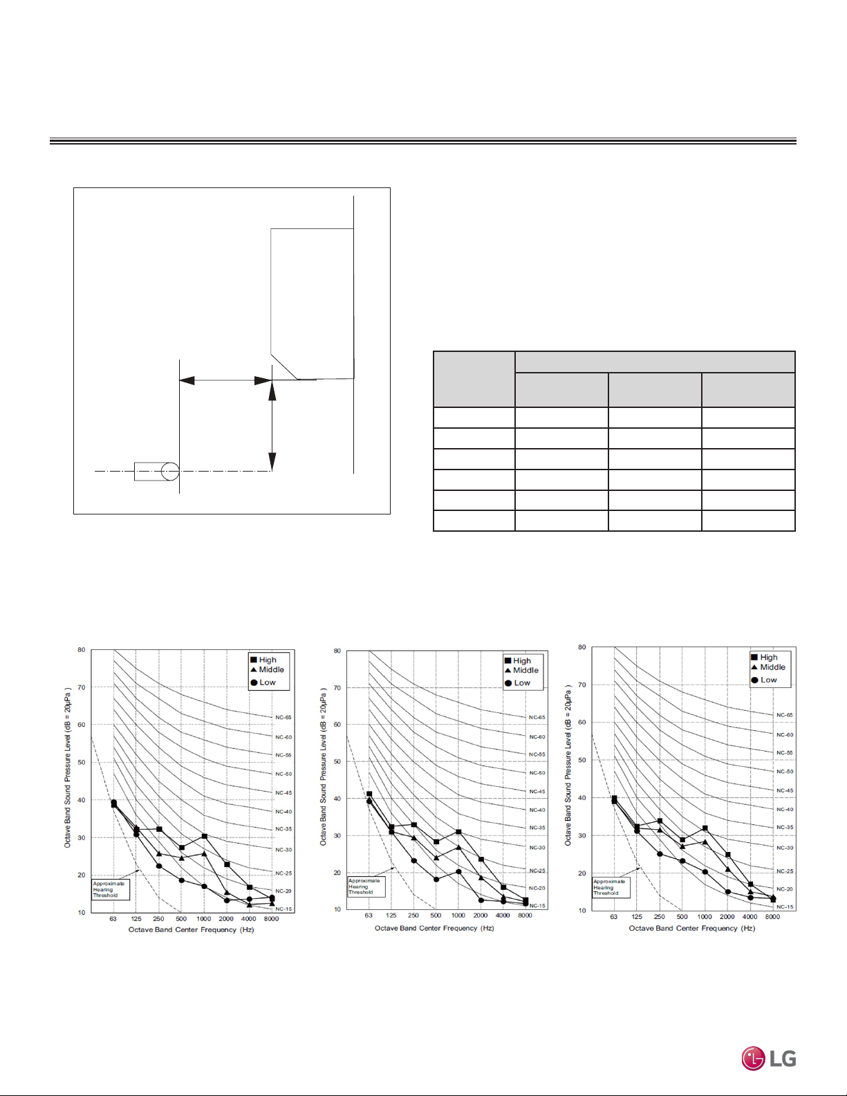
MULTI
F
MAX
MULTI
F
STANDARD WALL-MOUNTED INDOOR UNITS
2.6 ft.
3.3 ft.
Microphone
Acoustic Data
Figure 63: Sound Pressure Level Measurement Location.
• Measurement taken 2.6′ below the bottom of the unit and at a
distance of 3.3′ from face of unit.
• Measurements taken with no attenuation and units operating at full
load normal operating condition.
• Sound level will vary depending on a range of factors such as
construction (acoustic absorption coefficient) of particular area in
which the equipment is installed.
• Sound power levels are measured in dB(A)±1.
• Tested in anechoic chamber per ISO Standard 3745.
Table 27: Sound Pressure Levels (dB[A]).
Sound Pressure Levels (dB[A]) (Cooling and Heating)
Model No.
LMN079HVT 35 31 26
LSN090HSV5 36 32 27
LSN120HSV5 38 34 29
LMN159HVT 42 38 32
LSN180HSV5 44 38 34
LMN249HVT 46 41 36
High Fan Speed
Medium Fan
Speed
Low Fan Speed
Figure 64:LMN079HVT, LSN090HSV5, and LSN120HSV5 Sound Pressure Level Diagrams.
LMN079HVT
LSN090HSV5
Multi F and Multi F MAX Indoor Unit Engineering Manual
LSN120HSV5
58 | STD. WALL-MOUNTED
©LG Electronics U.S.A., Inc., Englewood Cliffs, NJ. All rights reserved. “LG” is a registered trademark of LG Corp.
Due to our policy of continuous product innovation, some specications may change without notication.
Page 59
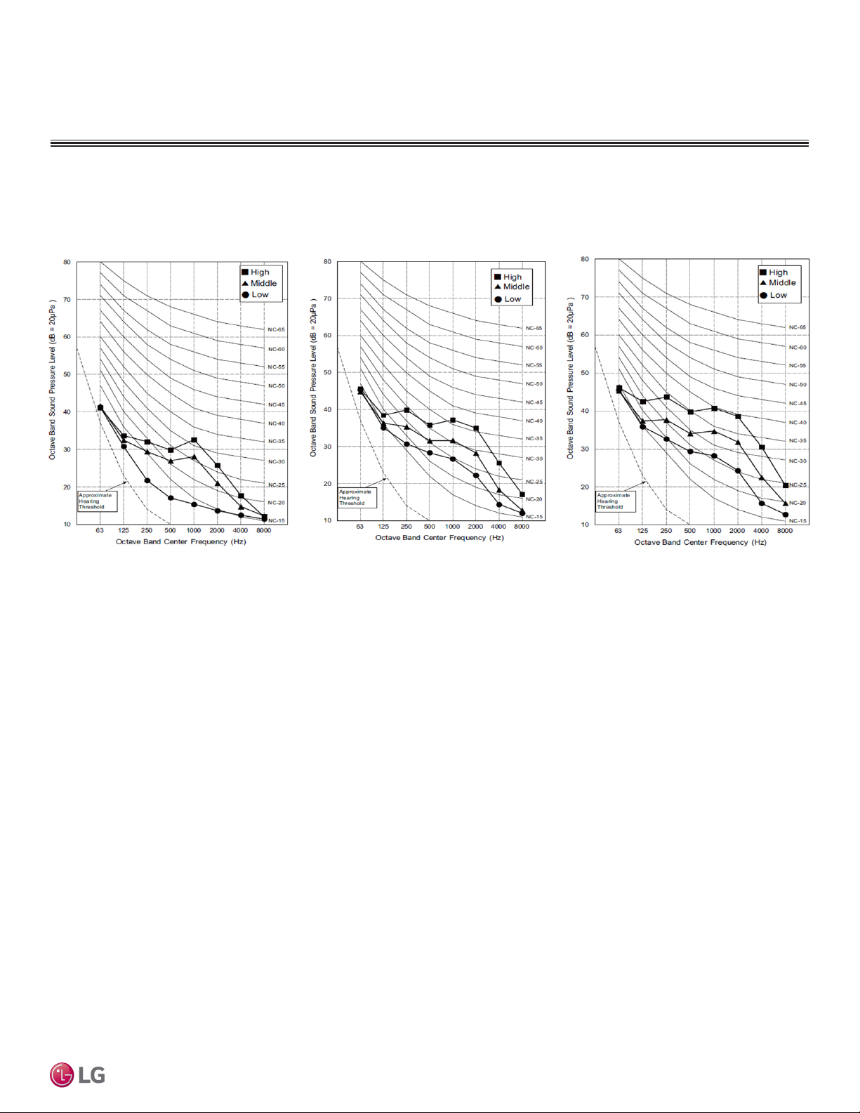
MULTI
F
MAX
MULTI
F
STANDARD WALL-MOUNTED INDOOR UNITS
Figure 65:LMN159HVT, LSN180HSV5, and LMN249HVT Sound Pressure Level Diagrams.
Acoustic Data
LMN159HVT
LSN180HSV5
LMN249HVT
Standard Wall-Mounted
Due to our policy of continuous product innovation, some specications may change without notication.
©LG Electronics U.S.A., Inc., Englewood Cliffs, NJ. All rights reserved. “LG” is a registered trademark of LG Corp.
STD. WALL-MOUNTED | 59
Page 60

MULTI
F
MAX
MULTI
F
STANDARD WALL-MOUNTED INDOOR UNITS
Air Velocity and Temperature Distribution
Figure 66:LMN079HVT, LSN090HSV5, LSN120HSV5, LMN159HVT Air Velocity and Temperature Distribution Charts.
Figure 67:LSN180HSV5 Air Velocity and Temperature Distribution Charts.
Multi F and Multi F MAX Indoor Unit Engineering Manual
60 | STD. WALL-MOUNTED
Due to our policy of continuous product innovation, some specications may change without notication.
©LG Electronics U.S.A., Inc., Englewood Cliffs, NJ. All rights reserved. “LG” is a registered trademark of LG Corp.
Page 61

MULTI
F
MAX
MULTI
F
STANDARD WALL-MOUNTED INDOOR UNITS
Figure 68:LMN249HVT Air Velocity and Temperature Distribution Charts.
Air Velocity and Temperature Distribution
Standard Wall-Mounted
Due to our policy of continuous product innovation, some specications may change without notication.
©LG Electronics U.S.A., Inc., Englewood Cliffs, NJ. All rights reserved. “LG” is a registered trademark of LG Corp.
STD. WALL-MOUNTED | 61
Page 62
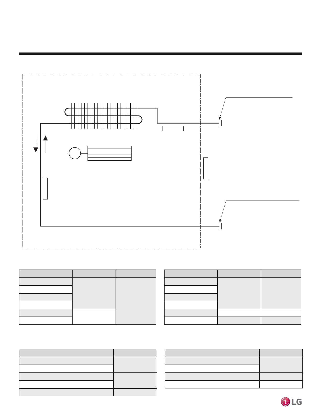
MULTI
F
MAX
MULTI
F
STANDARD WALL-MOUNTED INDOOR UNITS
Refrigerant Flow Diagram
Figure 69:Multi F Standard Wall-Mounted Indoor Unit Refrigerant Flow Diagram.
Heating
Cooling
Evaporator Inlet Temperature
Thermistor for
Heat Exchanger
Cross Flow Fan
M
Thermistor for Evaporator
Outlet Temperature
Gas pipe connection port
(flare connection)
Indoor Air Temperature
Thermistor for
Liquid pipe connection port
(flare connection)
Table 28: Multi F Standard Wall-Mounted Indoor Unit
Refrigerant Pipe Sizes.
Model No. Vapor (inch) Liquid (inch)
LMN079HVT
LSN090HSV5
Multi F and Multi F MAX Indoor Unit Engineering Manual
LSN120HSV5
LMN159HVT
LSN180HSV5
LMN249HVT
Table 30: Multi F LSNxxxHSV5 Standard Wall-Mounted Indoor Unit
Thermistor Details.
Description (Based on Cooling Mode) PCB Connector
Indoor Air Temperature Thermistor
Evaporator Inlet Temperature Thermistor
Evaporator Middle Temperature Thermistor
Evaporator Outlet Temperature Thermistor
Water Level Sensor (Optional) CN-TH3
62 | STD. WALL-MOUNTED
Ø3/8
Ø1/4
Ø1/2
CN-TH1
CN-TH2
Due to our policy of continuous product innovation, some specications may change without notication.
©LG Electronics U.S.A., Inc., Englewood Cliffs, NJ. All rights reserved. “LG” is a registered trademark of LG Corp.
Table 29: Multi F Standard Wall-Mounted Indoor Unit
Refrigerant Pipe Connections.
Table 31: Multi F LMNxxxHVT Standard Wall-Mounted Indoor Unit
Thermistor Details.
Evaporator Outlet Temperature Thermistor CN-TH2
Model No. Vapor (inch) Liquid (inch)
LMN079HVT
LSN090HSV5
LSN120HSV5
LMN159HVT
LSN180HSV5 Ø5/8 Ø3/8
LMN249HVT Ø1/2 Ø1/4
Description (Based on Cooling Mode) PCB Connector
Indoor Air Temperature Thermistor
Evaporator Inlet Temperature Thermistor
Water Level Sensor (Optional) CN-TH3
Ø3/8 Ø1/4
CN-TH1
Page 63

MULTI
F
MAX
MULTI
F
STANDARD WALL-MOUNTED INDOOR UNITS
Figure 70:Multi F Standard Wall-Mounted LSN090HSV5, LSN120HSV5, LSN180HSV5 Indoor Units Wiring Diagram.
Wiring Diagram
Standard Wall-Mounted
Due to our policy of continuous product innovation, some specications may change without notication.
©LG Electronics U.S.A., Inc., Englewood Cliffs, NJ. All rights reserved. “LG” is a registered trademark of LG Corp.
STD. WALL-MOUNTED | 63
Page 64
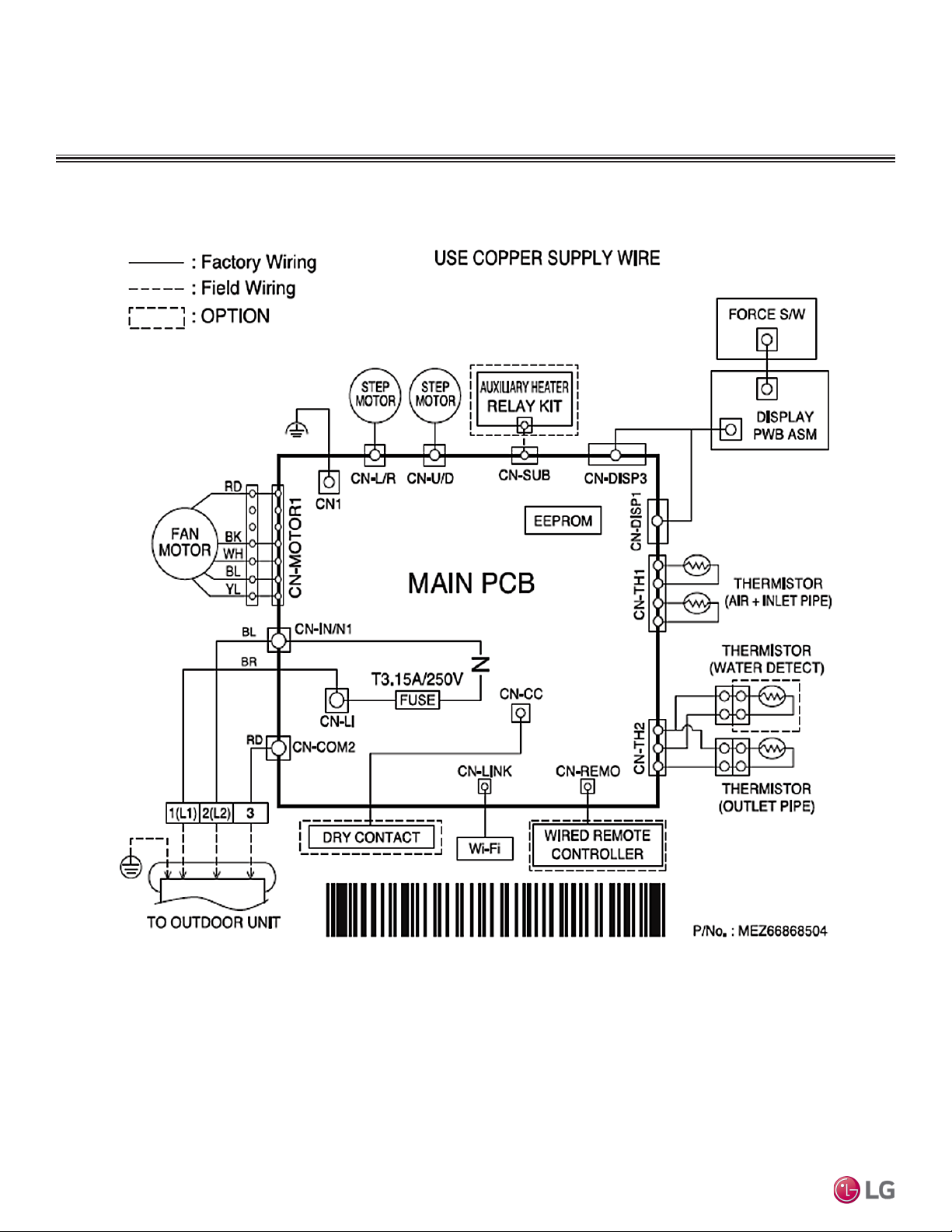
MULTI
F
MAX
MULTI
F
STANDARD WALL-MOUNTED INDOOR UNITS
Wiring Diagram
Figure 71: Multi F Standard Wall-Mounted LMN079HVT, LMN159HVT, LMN249HVT Indoor Unit Wiring Diagram.
Multi F and Multi F MAX Indoor Unit Engineering Manual
64 | STD. WALL-MOUNTED
Due to our policy of continuous product innovation, some specications may change without notication.
©LG Electronics U.S.A., Inc., Englewood Cliffs, NJ. All rights reserved. “LG” is a registered trademark of LG Corp.
Page 65
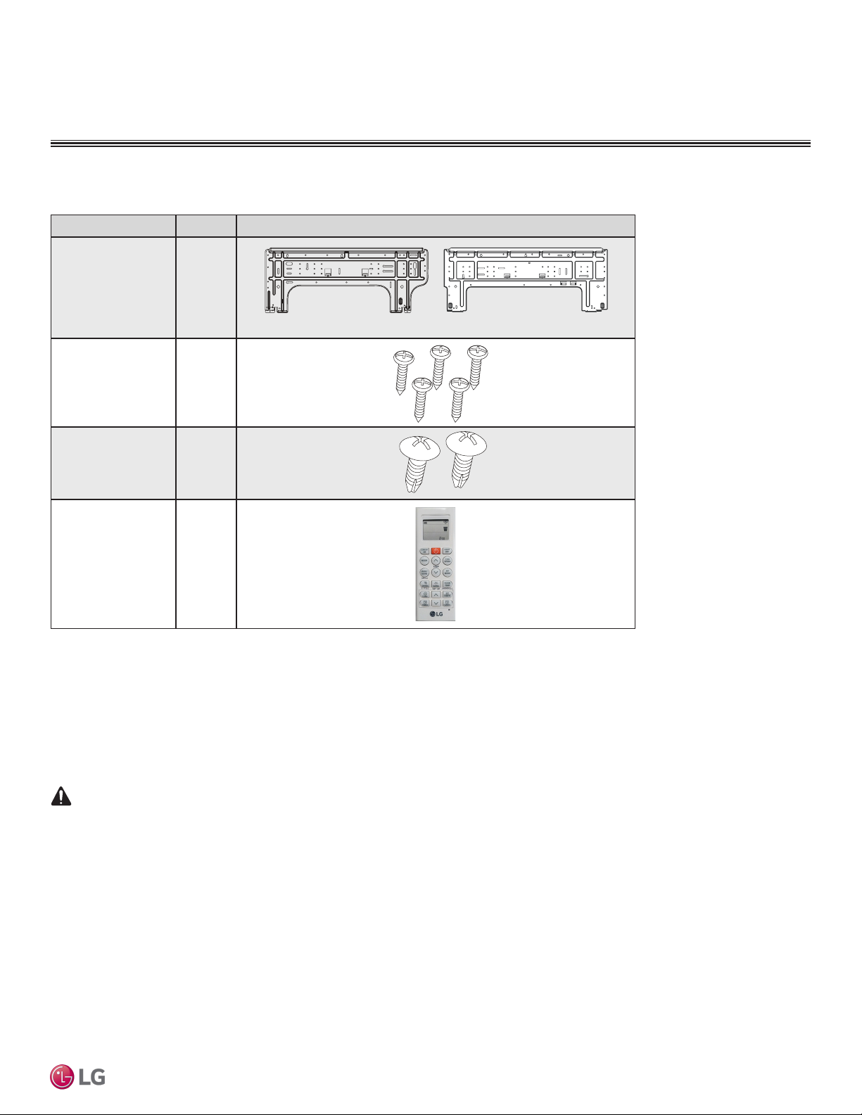
MULTI
F
MAX
MULTI
F
STANDARD WALL-MOUNTED INDOOR UNITS
7,000 ~ 15,000 Btu/h Indoor Units
WARNING
Factory Supplied Parts
Table 32: Parts Table.
Part Quantity Image
Installation Plate One (1)
Type “A” Screws Five (5)
Type “B” Screws
(M4 x 12L)
Two (2)
Factory Supplied Parts and Materials
18,000 and 24,000 Btu/h Indoor Units
Standard Wall-Mounted
Wireless
Controller with Holder
AKB74955602
Factory Supplied Materials
• Owner’s Manual
• Installation Manual
Installation work must be performed by trained personnel and in accordance with national wiring standards and all local or other applicable codes.
Improper installation can result in re, electric shock, physical injury, or death.
Note:
Read all instructions before installing this product. Become familiar with the unit’s components and connections, and the order of installation. Incorrect
installation can degrade or prevent proper operation.
One (1)
Required Tools
• Level
• Screwdriver
• Electric drill
• Hole core drill
• Flaring tool set
• Spanner (Half union)
• Thermometer
Due to our policy of continuous product innovation, some specications may change without notication.
©LG Electronics U.S.A., Inc., Englewood Cliffs, NJ. All rights reserved. “LG” is a registered trademark of LG Corp.
STD. WALL-MOUNTED | 65
Page 66
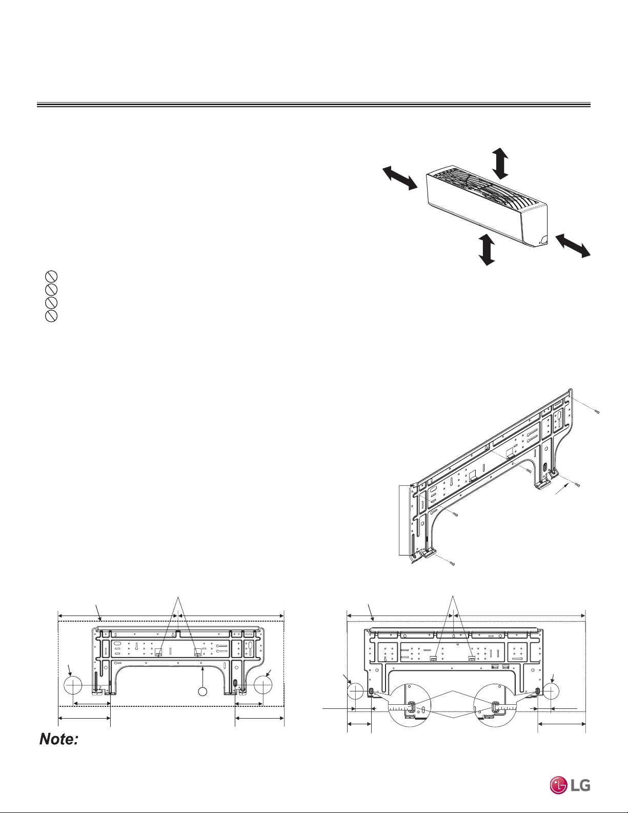
MULTI
F
MAX
MULTI
F
>4 inches
Recommended height
>6-1/2 feet from floor
>4 inches
≥5 inches
Installation Plate
Frame
Hooks
Type "A" Screws
Ø2-3/4 inches
Place a level on raised tab
STANDARD WALL-MOUNTED INDOOR UNITS
Right rear piping
Left rear piping
Installation and Best Layout Practices
Selecting the Best Location
Figure 72:Minimum Clearance Requirements.
Do’s
• Place the unit where air circulation will not be blocked.
• Place the unit where drainage can be obtained easily.
• Place the unit where noise prevention is taken into consideration.
• Ensure there is sufficient space from the ceiling and floor.
• Ensure there is sufficient maintenance space.
• Locate the indoor unit where it can be easily connected to the outdoor unit or branch
distribution unit.
Don’ts
• Do not install the unit near a heat or steam source, or where considerable amounts of oil, iron powder, or flour are used.
• Do not install the unit where sulfuric acid and flammable or corrosive gases are generated, vented into, or stored.
• Do not install the unit near high-frequency generators.
• Do not install the unit near a doorway.
The unit may be damaged, may malfunction, and / or will not operate as designed if installed in any of the conditions listed.
Installing in an Area Exposed to Unconditioned Air
In some installation applications, areas (floors, walls) in some rooms may be exposed to unconditioned air (room may be above or next to an
unheated garage or storeroom). To countermeasure:
• Verify that carpet is or will be installed (carpet may increase the temperature by three degrees).
• Add insulation between the floor joists.
• Install radiant heat or another type of heating system to the floor.
Figure 73:Installation Plate—
Side View.
Mounting the Installation Plate
The mounting wall should be strong and solid enough to protect the unit from
vibration.
• Mount the installation plate on the wall using the Type “A” screws. If mounting
the unit on concrete, consider using anchor bolts.
• Always mount the installation plate horizontally. Measure the wall and mark the
centerline using thread and a level.
Figure 74:Installation Plate for LMN079HVT, LSN090HSV5,
LSN120HSV5, and LMN159HVT Units. Figure 75:Installation Plate for LSN180HSV5 and LMN249HVT Units.
Multi F and Multi F MAX Indoor Unit Engineering Manual
Unit Outline
Ø2-9/16
6-7/8
5-3/16 3-11/16
Place a level on raised tab
17-3/8 17-3/8
5
8-1/2
Ø2-9/16
Left rear
piping
2-23/32 inches
Unit Outline
4-1/8 inches
18-1/8 inches 22-7/16 inches
Installation Plate
Measuring Tape
Measuring Tape Hanger
Ø2-3/4 inches
Right rear
piping
2-7/32 inches
8-5/32 inches
If the unit is installed near a body of water, certain components are at risk of being corroded. Appropriate anti-corrosion methods should be
taken for the unit and all components.
66 | STD. WALL-MOUNTED
Due to our policy of continuous product innovation, some specications may change without notication.
©LG Electronics U.S.A., Inc., Englewood Cliffs, NJ. All rights reserved. “LG” is a registered trademark of LG Corp.
Page 67

MULTI
F
MAX
MULTI
F
Installation plate
Tubing Clamp
Right
Tubing Clamp
Down
Left
Back
Frame Cover
STANDARD WALL-MOUNTED INDOOR UNITS
Installation and Best Layout Practices
Preparing for Installation
Prepare the refrigerant piping and drain hose (indoor unit piping) for installation through the
wall: press on the top of the tubing clamp and slowly guide the piping / hose down (depending
on installation requirements, then to the left or right). Relock the tubing clamp after the piping /
hose are released.
Note:
Do not bend the piping / drain hose from side to side; it may damage the components.
Hanging the Indoor Unit Frame
1. Attach the three (3) hooks on the top of the indoor unit to the top edge of the installation plate. Verify the hooks are properly attached to the installation plate by gently
shaking the indoor unit from side to side.
2. Unlock the tubing clamp from the indoor unit frame. For easier access between the
bottom of the indoor unit and the wall, prop the clamp between the indoor unit frame
and installation plate.
3. Remove the screw covers at the bottom of the indoor unit, unscrew the two (2) screws,
remove the frame cover, remove the piping connection cover, and position the piping
for installation (down, back, left, or right).
Figure 76:Preparing for Installation.
Standard Wall-Mounted
Figure 77:Locking the Indoor Unit onto the Installation Plate.
Figure 79:Removing the Frame Cover.
Figure 81:Piping Installed to the Left.
Figure 78:Accessing the Back of the Indoor Unit.
Figure 80:Exterior Back View of Indoor Unit.
Figure 82:Piping Installed to the Right.
Connecting
pipe
Tape
Drain hose
Due to our policy of continuous product innovation, some specications may change without notication.
©LG Electronics U.S.A., Inc., Englewood Cliffs, NJ. All rights reserved. “LG” is a registered trademark of LG Corp.
Tape
Connecting
pipe
Drain hose
STD. WALL-MOUNTED | 67
Page 68

MULTI
F
MAX
MULTI
F
STANDARD WALL-MOUNTED INDOOR UNITS
Terminal block
Power wiring /
communications cable
Wired Remote Controlle
r
Terminal (Optional)
Cable restraint
GRN / YLW
GRN / YLW
Installation and Best Layout Practices
Power Wiring / Communications Cable Guidelines
• Follow manufacturer’s circuit diagrams in the technical manuals.
• Confirm power source specifications.
• Confirm that the electrical capacity is sufficient.
• Starting current must be maintained ±10 percent of the rated current marked on the outdoor unit name plate.
• Confirm cable thickness specifications.
• It is recommended that a circuit breaker is installed, especially if conditions could become wet or moist.
• Include a disconnect in the power wiring system, add an air gap contact separation of at least 1/8 inch in each active (phase) conductor.
• Loose wiring may cause unit to malfunction, overheat, and catch
fire, resulting in severe injury or death.
Figure 83: Connecting Power Wiring / Communications Cable.
Note:
• Terminal screws may become loose during transport. Properly
tighten the terminal connections during installation.
A voltage drop may cause the following problems:
• Magnetic switch vibration, fuse breaks, or disturbance to the
normal function of an overload protection device.
• Compressor will not receive the proper starting current.
Connect Power Wiring and
Communications Cable
1. Insert the power wiring / communications cable from the outdoor
unit or branch distribution unit (Multi F MAX systems only) through
the bottom of the indoor unit.
2. Connect each wire to its appropriate terminal on the indoor unit
control board. Verify that the color and terminal numbers from the
outdoor unit or branch distribution unit (Multi F MAX systems only)
wiring match the color and terminal numbers on the indoor unit.
3. Secure power wiring/communications cable with cable restraint.
Figure 84:Simplied View of Indoor Unit to Outdoor Unit / Branch
Distribution Unit Terminal Connections—LMN079HVT, LSN090HSV5,
LSN120HSV5 and LMN159HVT.
Outdoor Unit Terminal Block or
Multi F and Multi F MAX Indoor Unit Engineering Manual
GND
Indoor Unit Terminal Block
32(L2)1(L1)
BR
BL
RD
Branch Distribution Unit Terminal Block
(Multi F MAX Systems Only)
3 or S
GND
Figure 85:Simplied View of Indoor Unit to Outdoor Unit / Branch
Distribution Unit Terminal Connections— LSN180HSV5 and
LMN249HVT.
GND
Indoor Unit Terminal Block
1(L1 )2(L2)
BR
Outdoor Unit Terminal Block or
Branch Distribution Unit Terminal Block
(Multi F MAX Systems Only)
3
BL
RD
3 or S
GND
68 | STD. WALL-MOUNTED
Due to our policy of continuous product innovation, some specications may change without notication.
©LG Electronics U.S.A., Inc., Englewood Cliffs, NJ. All rights reserved. “LG” is a registered trademark of LG Corp.
Page 69
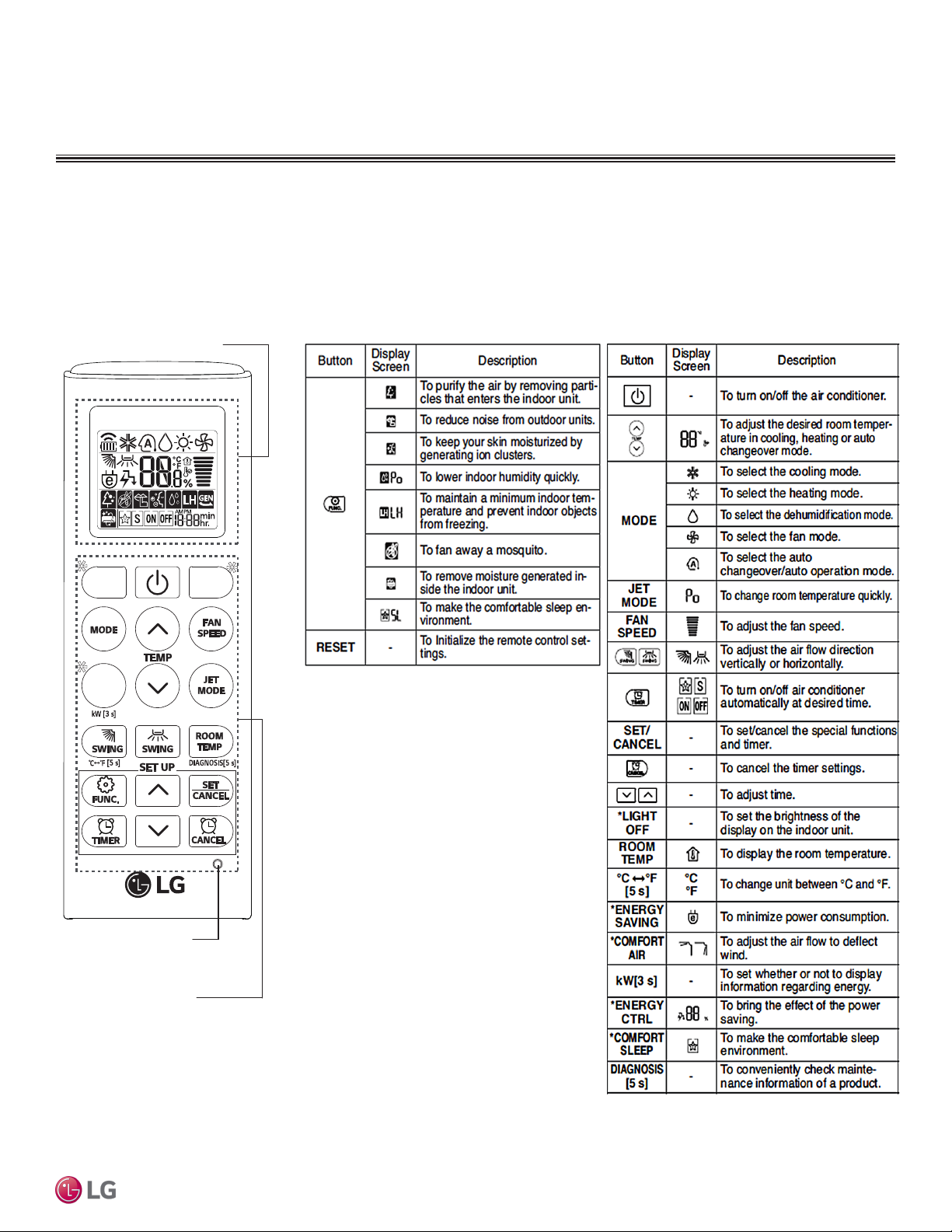
MULTI
F
MAX
MULTI
F
STANDARD WALL-MOUNTED INDOOR UNITS
Installation and Best Layout Practices
Controller Options
Standard wall-mounted indoor units include a wireless controller (AKB74955602), but optional LG-supplied wired controllers are available.
Wireless Controller
Table 33: AKB74955602 Wireless Controller Functions.Figure 86:AKB74955602 Wireless Controller.
Screen Display
Standard Wall-Mounted
*
*
*
RESET
Buttons
Due to our policy of continuous product innovation, some specications may change without notication.
©LG Electronics U.S.A., Inc., Englewood Cliffs, NJ. All rights reserved. “LG” is a registered trademark of LG Corp.
STD. WALL-MOUNTED | 69
Page 70

MULTI
F
MAX
MULTI
F
4 to 5 feet
above the floor
NO
NO
NO
YES
Remote Controller
TEMP
Remote Controller
TEMP
Re
m
ot
e
C
o
n
t
r
ol
l
er
TEMP
STANDARD WALL-MOUNTED INDOOR UNITS
Indoor Unit Terminal Block
GRN / YLW
Indoor Unit Terminal Block
GRN / YLW
(Multi F MAX Systems Only)
To Wired Controller
Installation and Best Layout Practices
Wired Controller Connections
Figure 87:Wired Controller Connection on Indoor Unit Terminal Block—
LMN079HVT, LSN090HSV5, LSN120HSV5, and LMN159HVT Models.
GND
1(L1 )2(L2)
BR
BL
3
RD
To Outdoor Unit or Branch Distribution Unit
CN-REMO
To Wired Controller
Figure 88:Wired Controller Connection on Indoor Unit Terminal Block—
LSN180HSV5 and LMN249HVT Models.
GND
1(L1 )2(L2)
BR
To Outdoor Unit or Branch Distribution Unit
(Multi F MAX Systems Only)
Wired Controller Placement
Wired controllers include a sensor to detect room temperature. To maintain comfort
levels in the conditioned space, the wired controller must be installed in a location away
from direct sunlight, high humidity, and where it could be directly exposed to cold air.
Controller must be installed four (4) to five (5) feet above the floor where its LED display
can be read easily, in an area with good air circulation, and where it can detect an average room temperature.
Do not install the wired controller near or in:
• Drafts or dead spots behind doors and in corners
• Hot or cold air from ducts
• Radiant heat from the sun or appliances
• Concealed pipes and chimneys
• An area where temperatures are uncontrolled, such as an outside wall
CN-REMO
BL
3
RD
Figure 89:Proper Location for the Wired Controller.
Multi F and Multi F MAX Indoor Unit Engineering Manual
70 | STD. WALL-MOUNTED
Due to our policy of continuous product innovation, some specications may change without notication.
©LG Electronics U.S.A., Inc., Englewood Cliffs, NJ. All rights reserved. “LG” is a registered trademark of LG Corp.
Page 71
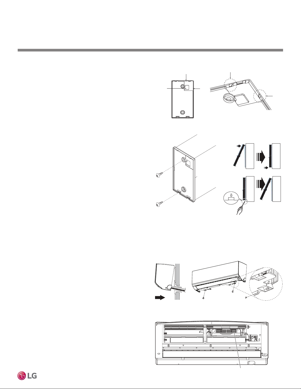
MULTI
F
MAX
MULTI
F
Top
Wall Wa ll
Wall Wall
Installing the Controller
Removing the Controller
STANDARD WALL-MOUNTED INDOOR UNITS
Filter
Installation and Best Layout Practices
Hanging the Wired Controller
1. The controller wiring / cable can be installed in one of three direc-
tions: top, back, or on the right side. If top or right side installation
is desired, remove cable guide grooves on the controller, and
then position wiring / cable on applicable side.
2. Choose and mark the area of installation. Use the provided parts
and screw the wall plate into place. Install the controller wall plate
to fit the electrical box if one is present. Ensure that no gaps exist
between the wall plate and the wall itself.
3. Arrange wiring / cables so as not to interfere with the controller
circuitry. Position the wired controller on the wall plate. Snap into
place by pressing the bottom part of the wired controller onto
the wall plate. Make sure that no gaps exist between the wired
controller and the wall plate on all sides.
4. To remove wired controller from the wall plate, insert a screw-
driver into the two holes at the bottom. Twist screwdriver to
release controller. Do not damage the controller components
when removing.
Figure 91:Removing the Cable Guide Grooves.
Top
Back
Figure 92:Attaching the Wall Plate.
Right
Side
Figure 93:Installing / Removing
the Controller.
Right
Side
Standard Wall-Mounted
Assigning the Thermistor for Temperature Detection
Each indoor unit includes a return air thermistor assigned to sense the temperature. If a wired controller is installed, there is a choice of
sensing temperature with either the indoor unit return air thermistor or the thermistor in the wired controller. It is also an option to set both
thermistors to sense temperature so that indoor unit bases its operation on the first thermistor to reach the designated temperature differential. For applicable indoor units, an optional Remote Temperature Sensor can be used in lieu of the return air thermistor—either alone or in
conjunction with a wired controller thermistor as previously described.
Finalizing Indoor Unit Installation
1. Move the tubing clamp to its original position.
2. Ensure the three (3) hooks are properly attached to the installa-
tion plate by gently shaking the indoor unit from side to side.
3. Press the bottom left and right sides of the indoor unit against the
installation plate until the hooks click firmly into their slots.
4. Using two (2) Type “C” screws, secure the bottom of the indoor
unit to the installation plate.
5. Remove the two (2) tabs from the filter.
6. Replace the frame cover.
Figure 90:Attach Bottom of Indoor Unit to Installation Plate.
Type 'C' screws
Figure 94:Removing the Filter Tabs.
Due to our policy of continuous product innovation, some specications may change without notication.
©LG Electronics U.S.A., Inc., Englewood Cliffs, NJ. All rights reserved. “LG” is a registered trademark of LG Corp.
STD. WALL-MOUNTED | 71
Page 72

CEILING-CONCEALED
DUCT (LOW STATIC)
INDOOR UNIT DATA
“Mechanical Specifications” on page 73
“General Data / Specifications” on page 74
“Dimensions” on page 75
“Cooling Capacity Table” on page 76
“Heating Capacity Table” on page 78
“External Static Pressure” on page 79
“Acoustic Data” on page 80
“Refrigerant Flow Diagram” on page 81
“Wiring Diagram” on page 83
“Factory Supplied Parts and Materials” on page 84
“Installation and Best Layout Practices” on page 85
Page 73
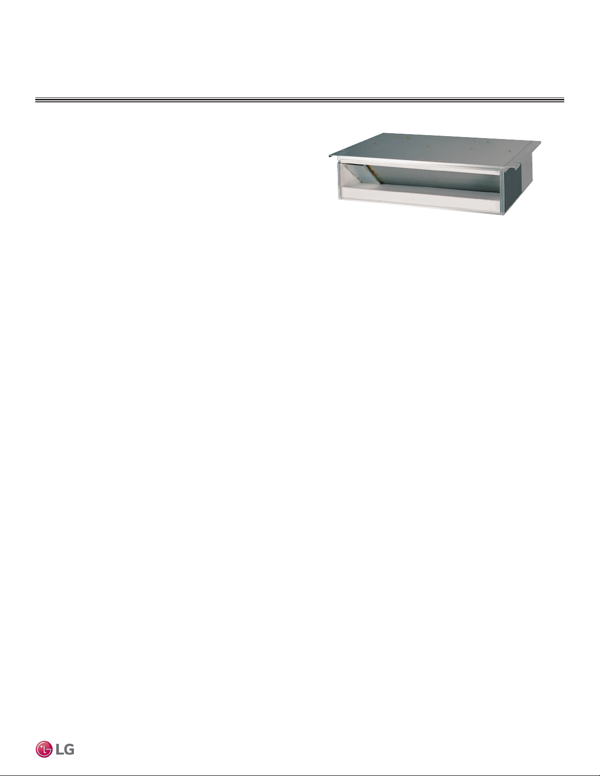
DUCT (LOW STATIC) INDOOR UNITS
MULTI
F
MAX
MULTI
F
Mechanical Specications and Features
Ceiling-Concealed Duct (Low Static)
Indoor Unit
General
All LG indoor units are factory assembled, wired, piped, and provided with a control circuit board, fan, and motor. Ceiling-Concealed
Duct (Low Static) units have a sound rating no higher than 36 dB(A)
as tested per KSA0701 ISO Standard 3745, and are designed for
low-static pressure up to 0.20″WG.
Coil
Indoor unit coils are factory built and are comprised of aluminum fins
mechanically bonded to copper tubing. Each unit has two rows of
coils, which are pressure tested at the factory. Each unit is provided
with a factory installed condensate drain pan below the coil.
Refrigerant System
System is designed for use with R410A refrigerant. The refrigeration
circuit is pressure-tested at the factory and shipped with a holding
charge of helium gas. Refrigerant pipe connections are 45° flare,
and all refrigerant lines from the outdoor unit to the indoor units must
be field insulated.
Electrical
Each indoor unit is designed to operate using 208–230/60/1 power
with voltage variances of ±10%.
Casing
The case has a low profile design with a maximum height of 7.5
inches designed to mount fully concealed above a finished ceiling in
as little as 8 inches vertical space. Casing is manufactured of galvanized steel plate, and provided with hanger brackets designed to
support the weight on four corners. Unit has a front horizontal supply
air discharge outlet, and one rear horizontal return air inlet; unit is
also field-convertible for a rear bottom return.
Fan Assembly and Control
The units have at least two direct-drive, Sirocco fans made of
high strength ABS HT-700 polymeric resin that are statically and
dynamically balanced. The fans are mounted on a common brushless digitally controlled (BLDC) motor with permanently lubricated
and sealed ball bearings. The fan / motor assembly is mounted on
vibration-attenuating rubber grommets. Fan speed is controlled using
a microprocessor-based direct digital control algorithm. The indoor
fan has Low, Med, High, and Auto settings for Cooling mode; and
Figure 95: Ceiling-Concealed Duct (Low Static) Indoor Unit.
has Low, Med, High, and Auto settings for Heating mode. Each of the
settings can be field-adjusted from the factory setting (RPM / ESP).
The Auto setting adjusts the fan speed based on the difference
between the controller set-point and space temperature.
Air Filter
Return air is filtered with a factory-supplied, removable, washable
filter accessible from the rear of the indoor unit.
Microprocessor Control
The unit is provided with an integrated control panel to communicate
with the outdoor unit. All unit operation parameters are stored in nonvolatile memory residing on the unit microprocessor. The microprocessor controls space temperature through using the value provided
by the temperature sensor within the indoor unit. The microprocessor
control will activate indoor unit operation when the indoor room temperature falls below or rises above a setpoint temperature, at which
point, a signal is sent to the outdoor unit to begin the appropriate
mode. The microprocessor will also provide self-diagnostics and auto
restart functions. A field-supplied four-wire power / communications
cable must be installed to connect the indoor unit(s) to the outdoor
unit.
Controls
The indoor unit is supplied with an LG wired controller. Communication between the indoor units and the outdoor unit is accomplished
through 18 AWG, four-core, stranded and shielded power / communication cable.
Condensate Lift/Pump
The indoor unit is provided with an externally mounted, factory
installed and wired condensate lift/pump capable of providing a minimum 27.5 inch lift from the bottom surface of the unit. Drain pump
has a safety switch to shut off the indoor unit if the condensate rises
too high in the drain pan.
Ceiling-Concealed Duct (Low Static)
Features
• Inverter (Variable speed fan)
• External mounted drain pump
• Control lock function
• Auto operation
• Auto restart operation
• Dehumidification function
• Two thermistor control
• External static pressure control
Due to our policy of continuous product innovation, some specications may change without notication.
©LG Electronics U.S.A., Inc., Englewood Cliffs, NJ. All rights reserved. “LG” is a registered trademark of LG Corp.
• Self-diagnostics function
• Group control
• Wired thermostat included
DUCT (LOW STATIC) | 73
Page 74

DUCT (LOW STATIC) INDOOR UNITS
MULTI
F
MAX
MULTI
F
General Data / Specications
Table 34: Multi F Ceiling-Concealed Low-Static Ducted Indoor Unit General Data.
Model Name LDN097HV4 LDN127HV4 LMDN186HV
Nominal Cooling Capacity (Btu/h)
Nominal Heating Capacity (Btu/h)
1
1
Operating Range
Cooling (°F WB)
Heating (°F DB)
Fan
Type
Motor Output (W) x Qty.
Motor/Drive
Airflow Rate CFM (H/M/L)
Factory Set External Static Pressure (in. wg)
Max. External Static Pressure (in. wg)
Unit Data
Refrigerant Type
2
Refrigerant Control
Power Supply V, Ø, Hz3
Rated Amps (A)
Sound Pressure Level ±3 dB(A) (H/M/L)4
Dimensions (W x H x D, in.)
27-9/16 x 7-15/32 x 27-9/16 35-7/16 x 7-15/32 x 27-9/16
Net Unit Weight (lbs.)
Shipping Weight (lbs.)
Power Wiring / Communications Cable (No. x AWG)5
Heat Exchanger (Row x Column x Fin / inch) x Number
Piping
Liquid (in.)
Vapor (in.)
Drain O.D. / I.D. (in.)
1
Nominal capacity is rated 0 ft. above sea level with corresponding refrigerant piping length in
Multi F and Multi F MAX Indoor Unit Engineering Manual
accordance with standard length of each outdoor unit and a 0 ft. level difference between outdoor and
indoor units. All capacities are net with a combination ratio between 95 – 105%.
Nominal cooling capacity rating obtained with air entering the indoor unit at 80ºF dry bulb (DB) and 67ºF
wet bulb (WB) and outdoor ambient conditions of 95ºF dry bulb (DB) and 75ºF wet bulb (WB).
Nominal heating capacity rating obtained with air entering the indoor unit at 70ºF dry bulb (DB) and 60ºF
wet bulb (WB) and outdoor ambient conditions of 47ºF dry bulb (DB) and 43ºF wet bulb (WB).
2
This unit comes with a dry helium charge.
9,000 12,000 18,000
10,400 13,800 20,800
19 x 1 5 x 1, 19 x 1
Brushless Digitally Controlled / Direct
318 / 247 / 194 353 / 300 / 247 530 / 441 / 353
0.40 0.80
30 / 26 / 23 31 / 28 / 27 36 / 34 / 31
39 51
46 60 57
(2 x 11 x 14) x 1 (2 x 11 x 18) x 1
3/8 1/2
3
Acceptable operating voltage: 187V-253V.
4
Sound pressure levels are tested in an anechoic chamber under ISO Standard 3745 and are the
same in both cooling and heating mode. These values can increase due to ambient conditions during
operation.
5
All power wiring / communications cable to the IDUs be minimum 18 AWG, 4-conductor, stranded,
shielded or unshielded (if shielded, must be grounded to chassis at ODU only) and must comply with
applicable local and national codes.
57-77
59-81
Sirocco
0.10
0.20
R410A
EEV
208-230, 1, 60
4 x 18
1/4
1-1/4, 1
74 | D UCT (LOW STATIC)
Due to our policy of continuous product innovation, some specications may change without notication.
©LG Electronics U.S.A., Inc., Englewood Cliffs, NJ. All rights reserved. “LG” is a registered trademark of LG Corp.
Page 75

DUCT (LOW STATIC) INDOOR UNITS
MULTI
F
MAX
MULTI
F
Figure 96:LDN097HV4, LDN127HV4, and LMDN186HV Dimensions.
Dimensions
Ceiling-Concealed Duct (Low Static)
Due to our policy of continuous product innovation, some specications may change without notication.
©LG Electronics U.S.A., Inc., Englewood Cliffs, NJ. All rights reserved. “LG” is a registered trademark of LG Corp.
DUCT (LOW STATIC) | 75
Page 76

DUCT (LOW STATIC) INDOOR UNITS
MULTI
F
MAX
MULTI
F
Cooling Capacity Table
Table 35: Multi F Ceiling-Concealed Duct (Low Static) Indoor Units Cooling Capacity Table.
Model No. /
Nominal Capacity
of Indoor Unit
(Btu/h)
LDN097HV4
9,000
LDN127HV4
12,000
Multi F and Multi F MAX Indoor Unit Engineering Manual
TC = Total Capacity (kBtu/h).
SHC: Sensible Heat Capacity (kBtu/h).
Nominal capacity as rated 0 ft. above sea level and a 0 ft. level difference between outdoor and indoor units. Corresponding refrigerant piping length is accordance with standard length of each outdoor unit.
Nominal cooling capacity rating obtained with air entering the indoor unit at 80ºF dry bulb (DB) and 67ºF wet bulb (WB), and outdoor ambient conditions of 95ºF dry bulb (DB) and 75ºF wet bulb (WB).
The shaded table columns and rows indicate reference data. When operating at this temperature, these values can be different if the system is not running consistently.
Outdoor Air
Temp.
(°F DB)
14 8.82 7.55 9.37 7.98 9.92 7.72 10.31 7.89 11.01 7.95 11.56 8.10
20 8.82 7.61 9.36 8.04 9.91 7.78 10.31 7.95 11.01 8.01 11.55 8.17
25 8.81 7.67 9.36 8.10 9.90 7.84 10.30 8.01 11.00 8.08 11.54 8.23
30 8.80 7.73 9.35 8.16 9.90 7.90 10.29 8.07 10.99 8.14 11.54 8.29
35 8.80 7.79 9.34 8.22 9.89 7.96 10.28 8.13 10.98 8.20 11.53 8.36
40 8.79 7.84 9.33 8.29 9.88 8.02 10.27 8.19 10.97 8.26 11.52 8.42
45 8.78 7.90 9.33 8.35 9.87 8.08 10.27 8.25 10.96 8.32 11.51 8.48
50 8.78 7.96 9.32 8.41 9.87 8.14 10.26 8.31 10.96 8.38 11.50 8.54
55 8.77 8.02 9.31 8.47 9.86 8.20 10.25 8.38 10.95 8.45 11.49 8.61
60 8.76 8.08 9.31 8.53 9.85 8.26 10.24 8.44 10.94 8.51 11.48 8.67
65 8.76 8.14 9.30 8.59 9.84 8.32 10.24 8.50 10.93 8.57 11.47 8.73
70 8.75 8.19 9.29 8.66 9.84 8.38 10.23 8.56 10.92 8.63 11.47 8.79
75 8.54 8.06 9.08 8.52 9.62 8.26 10.01 8.44 10.71 8.53 11.25 8.69
80 8.33 7.92 8.87 8.39 9.41 8.14 9.80 8.33 10.49 8.42 11.03 8.59
85 8.12 7.78 8.66 8.25 9.20 8.02 9.59 8.20 10.28 8.30 10.82 8.48
90 7.91 7.63 8.45 8.10 8.99 7.89 9.37 8.08 10.06 8.19 10.60 8.37
95 7.68 7.55 8.22 8.03 8.75 7.83 9.00 7.90 9.83 8.14 10.36 8.34
100 7.50 7.35 8.03 7.83 8.57 7.64 8.88 7.78 9.64 7.97 10.17 8.16
105 7.31 7.15 7.84 7.63 8.38 7.45 8.77 7.66 9.45 7.79 9.99 7.99
110 7.12 6.90 7.66 7.38 8.19 7.22 8.58 7.43 9.26 7.57 9.80 7.77
115 6.94 6.69 7.47 7.17 8.01 7.03 8.39 7.24 9.08 7.39 9.61 7.60
118 6.82 6.65 7.36 7.13 7.89 7.00 8.28 7.21 8.96 7.37 9.50 7.58
122 6.79 6.63 7.32 7.11 7.86 6.98 8.24 7.19 8.93 7.36 9.46 7.57
14 11.76 9.94 12.49 10.50 13.22 10.17 13.75 10.38 14.69 10.47 15.42 10.67
20 11.75 10.02 12.48 10.58 13.21 10.25 13.74 10.46 14.67 10.55 15.40 10.75
25 11.75 10.09 12.48 10.66 13.20 10.33 13.73 10.54 14.66 10.63 15.39 10.83
30 11.74 10.17 12.47 10.75 13.19 10.40 13.72 10.62 14.65 10.71 15.38 10.92
35 11.73 10.25 12.46 10.83 13.18 10.48 13.71 10.70 14.64 10.79 15.37 11.00
40 11.72 10.33 12.45 10.91 13.17 10.56 13.70 10.79 14.63 10.88 15.36 11.08
45 11.71 10.40 12.44 10.99 13.16 10.64 13.69 10.87 14.62 10.96 15.35 11.16
50 11.70 10.48 12.43 11.07 13.15 10.72 13.68 10.95 14.61 11.04 15.33 11.25
55 11.69 10.56 12.42 11.15 13.14 10.80 13.67 11.03 14.60 11.12 15.32 11.33
60 11.68 10.63 12.41 11.23 13.13 10.88 13.66 11.11 14.59 11.20 15.31 11.41
65 11.67 10.71 12.40 11.31 13.12 10.96 13.65 11.19 14.57 11.28 15.30 11.49
70 11.66 10.79 12.39 11.40 13.11 11.03 13.64 11.27 14.56 11.36 15.29 11.58
75 11.38 10.61 12.11 11.22 12.83 10.88 13.35 11.12 14.27 11.22 15.00 11.45
80 11.10 10.43 11.82 11.05 12.55 10.72 13.07 10.96 13.99 11.08 14.71 11.31
85 10.83 10.24 11.54 10.86 12.26 10.55 12.78 10.80 13.70 10.93 14.42 11.17
90 10.55 10.04 11.26 10.67 11.98 10.38 12.50 10.63 13.42 10.78 14.13 11.02
95 10.25 9.94 10.96 10.57 11.67 10.30 12.00 10.40 13.10 10.72 13.81 10.97
100 10.00 9.67 10.71 10.31 11.42 10.06 11.84 10.24 12.85 10.49 13.56 10.75
105 9.75 9.41 10.46 10.04 11.17 9.81 11.69 10.08 12.60 10.26 13.31 10.52
110 9.50 9.09 10.21 9.72 10.92 9.51 11.44 9.78 12.35 9.97 13.07 10.24
115 9.25 8.81 9.96 9.44 10.67 9.26 11.19 9.53 12.10 9.73 12.82 10.00
118 9.10 8.75 9.81 9.39 10.52 9.21 11.04 9.49 11.95 9.70 12.67 9.98
122 9.05 8.73 9.76 9.37 10.48 9.19 10.99 9.47 11.90 9.69 12.62 9.97
68 / 57 73 / 61 77 / 64 80 / 67 86 / 72 90 / 75
TC SHC TC SHC TC SHC TC SHC TC SHC TC SHC
Indoor Air Temp. °F DB / °F WB
76 | DUCT (LOW STATIC)
Due to our policy of continuous product innovation, some specications may change without notication.
©LG Electronics U.S.A., Inc., Englewood Cliffs, NJ. All rights reserved. “LG” is a registered trademark of LG Corp.
Page 77

DUCT (LOW STATIC) INDOOR UNITS
MULTI
F
MAX
MULTI
F
Cooling Capacity Table
Table 36: Multi F Ceiling-Concealed Duct (Low Static) Indoor Units Cooling Capacity Table (continued).
Model No. /
Nominal Capacity
of Indoor Unit
(Btu/h)
LMDN186HV
18,000
TC = Total Capacity (kBtu/h).
SHC: Sensible Heat Capacity (kBtu/h).
Nominal capacity as rated 0 ft. above sea level and a 0 ft. level difference between outdoor and indoor units. Corresponding refrigerant piping length is accordance with standard length of each outdoor unit.
Nominal cooling capacity rating obtained with air entering the indoor unit at 80ºF dry bulb (DB) and 67ºF wet bulb (WB), and outdoor ambient conditions of 95ºF dry bulb (DB) and 75ºF wet bulb (WB).
The shaded table columns and rows indicate reference data. When operating at this temperature, these values can be different if the system is not running consistently.
Outdoor Air
Temp.
(°F DB)
14 17.65 13.09 18.74 13.83 19.84 13.39 20.63 13.67 22.03 13.79 23.12 14.05
20 17.63 13.20 18.73 13.94 19.82 13.50 20.61 13.78 22.01 13.90 23.11 14.16
25 17.62 13.30 18.71 14.05 19.81 13.60 20.60 13.89 22.00 14.01 23.09 14.27
30 17.60 13.40 18.70 14.16 19.79 13.71 20.58 13.99 21.98 14.11 23.07 14.38
35 17.59 13.50 18.68 14.26 19.78 13.81 20.57 14.10 21.96 14.22 23.05 14.49
40 17.58 13.60 18.67 14.37 19.76 13.91 20.55 14.21 21.94 14.33 23.04 14.60
45 17.56 13.71 18.66 14.48 19.75 14.02 20.53 14.31 21.93 14.43 23.02 14.71
50 17.55 13.81 18.64 14.58 19.73 14.12 20.52 14.42 21.91 14.54 23.00 14.82
55 17.54 13.91 18.63 14.69 19.72 14.23 20.50 14.52 21.89 14.65 22.98 14.92
60 17.52 14.01 18.61 14.80 19.70 14.33 20.49 14.63 21.88 14.75 22.97 15.03
65 17.51 14.11 18.60 14.90 19.69 14.43 20.47 14.74 21.86 14.86 22.95 15.14
70 17.50 14.21 18.58 15.01 19.67 14.53 20.46 14.84 21.84 14.97 22.93 15.25
75 17.08 13.98 18.16 14.78 19.24 14.33 20.03 14.64 21.41 14.78 22.50 15.08
80 16.66 13.74 17.74 14.55 18.82 14.12 19.60 14.44 20.98 14.60 22.06 14.90
85 16.24 13.49 17.32 14.30 18.40 13.90 19.17 14.23 20.55 14.40 21.63 14.71
90 15.82 13.23 16.90 14.06 17.97 13.68 18.75 14.01 20.12 14.20 21.20 14.52
95 15.37 13.09 16.44 13.93 17.51 13.57 18.00 13.70 19.65 14.12 20.72 14.46
100 14.99 12.74 16.06 13.58 17.13 13.25 17.77 13.49 19.28 13.82 20.35 14.16
105 14.62 12.39 15.69 13.23 16.76 12.93 17.53 13.28 18.90 13.52 19.97 13.86
110 14.24 11.97 15.32 12.80 16.39 12.53 17.16 12.88 18.53 13.13 19.60 13.48
115 13.87 11.61 14.94 12.44 16.01 12.19 16.79 12.55 18.15 12.82 19.22 13.18
118 13.65 11.53 14.72 12.36 15.79 12.13 16.56 12.50 17.93 12.77 19.00 13.14
122 13.57 11.50 14.64 12.34 15.71 12.11 16.49 12.48 17.85 12.76 18.92 13.13
68 / 57 73 / 61 77 / 64 80 / 67 86 / 72 90 / 75
TC SHC TC SHC TC SHC TC SHC TC SHC TC SHC
Indoor Air Temp. °F DB / °F WB
Ceiling-Concealed Duct (Low Static)
Due to our policy of continuous product innovation, some specications may change without notication.
©LG Electronics U.S.A., Inc., Englewood Cliffs, NJ. All rights reserved. “LG” is a registered trademark of LG Corp.
DUCT (LOW STATIC) | 77
Page 78

DUCT (LOW STATIC) INDOOR UNITS
MULTI
F
MAX
MULTI
F
Heating Capacity Table
Table 37: Multi F Ceiling-Concealed Duct (Low Static) Indoor Units Heating Capacity Table.
Model No. /
Nominal Capacity of
Indoor Unit
(Btu/h)
LDN097HV4
9,000
LDN127HV4
12,000
LMDN186HV
18,000
Multi F and Multi F MAX Indoor Unit Engineering Manual
TC = Total Capacity (kBtu/h).
Nominal capacity as rated 0 ft. above sea level and a 0 ft. level difference between outdoor and indoor units. Corresponding refrigerant piping length is accordance with standard length of each outdoor unit.
Nominal heating capacity rating obtained with air entering the indoor unit at 70ºF dry bulb (DB) and 60ºF wet bulb (WB), and outdoor ambient conditions of 47ºF dry bulb (DB) and 43ºF wet bulb (WB).
Outdoor Air Temp. Indoor Air Temp. °F DB
61 64 68 70 72 75
°F DB °F WB
0 -0.4 5.35 5.28 5.23 5.20 5.12 4.90
5 4.5 6.03 5.95 5.90 5.88 5.80 5.58
10 9 6.71 6.63 6.58 6.56 6.48 6.26
17 15 7.61 7.54 7.49 7.46 7.39 7.14
20 19 7.95 7.88 7.83 7.80 7.72 7.46
25 23 8.52 8.44 8.39 8.37 8.29 7.99
30 28 9.01 8.93 8.88 8.86 8.78 8.52
35 32 9.50 9.42 9.37 9.34 9.27 9.04
40 36 9.94 9.86 9.81 9.78 9.71 9.48
45 41 10.37 10.30 10.25 10.22 10.15 9.92
47 43 10.55 10.48 10.43 10.40 10.32 10.10
50 46 10.72 10.64 10.59 10.57 10.49 10.24
55 51 11.00 10.93 10.88 10.85 10.78 10.48
60 56 11.00 10.93 10.88 10.85 10.78 10.52
63 59 11.00 10.93 10.88 10.85 10.78 10.55
68 64 11.00 10.93 10.88 10.85 10.78 10.60
0 -0.4 7.10 7.00 6.93 6.90 6.80 6.50
5 4.5 8.00 7.90 7.83 7.80 7.70 7.40
10 9 8.90 8.80 8.73 8.70 8.60 8.30
17 15 10.10 10.00 9.93 9.90 9.80 9.48
20 19 10.55 10.45 10.38 10.35 10.25 9.90
25 23 11.30 11.20 11.13 11.10 11.00 10.60
30 28 11.95 11.85 11.78 11.75 11.65 11.30
35 32 12.60 12.50 12.43 12.40 12.30 12.00
40 36 13.18 13.08 13.02 12.98 12.88 12.58
45 41 13.77 13.67 13.60 13.57 13.47 13.17
47 43 14.00 13.90 13.83 13.80 13.70 13.40
50 46 14.23 14.13 14.06 14.03 13.93 13.59
55 51 14.60 14.50 14.43 14.40 14.30 13.90
60 56 14.60 14.50 14.43 14.40 14.30 13.96
63 59 14.60 14.50 14.43 14.40 14.30 14.00
68 64 14.60 14.50 14.43 14.40 14.30 14.06
0 -0.4 10.70 10.55 10.45 10.40 10.25 9.80
5 4.5 12.06 11.91 11.81 11.76 11.61 11.15
10 9 13.41 13.26 13.16 13.11 12.96 12.51
17 15 15.22 15.07 14.97 14.92 14.77 14.29
20 19 15.90 15.75 15.65 15.60 15.45 14.92
25 23 17.03 16.88 16.78 16.73 16.58 15.98
30 28 18.01 17.86 17.76 17.71 17.56 17.03
35 32 18.99 18.84 18.74 18.69 18.54 18.09
40 36 19.87 19.72 19.62 19.57 19.42 18.97
45 41 20.75 20.60 20.50 20.45 20.30 19.85
47 43 21.10 20.95 20.85 20.80 20.65 20.20
50 46 21.44 21.29 21.19 21.14 20.99 20.48
55 51 22.01 21.86 21.75 21.70 21.55 20.95
60 56 22.01 21.86 21.75 21.70 21.55 21.04
63 59 22.01 21.86 21.75 21.70 21.55 21.10
68 64 22.01 21.86 21.75 21.70 21.55 21.20
TC TC TC TC TC TC
78 | DUCT (LOW STATIC)
Due to our policy of continuous product innovation, some specications may change without notication.
©LG Electronics U.S.A., Inc., Englewood Cliffs, NJ. All rights reserved. “LG” is a registered trademark of LG Corp.
Page 79

DUCT (LOW STATIC) INDOOR UNITS
MULTI
F
MAX
MULTI
F
Table 38: Multi F Ceiling-Concealed Duct (Low Static) External Static Pressure Setting Values Table.
Static Pressure (in. wg) 0.0 0.04 0.08 0.12 0.16 0.20
External Static Pressure
Model No. / Nominal Capacity
of Indoor Unit (Btu/h)
LDN097HV4
9,000
LDN127HV4
12,000
LMDN186HV
18,000
• To get the desired air flow and external static pressure combination, use the setting value from the table. Using a setting value other
than that listed in the table will not provide the desired combination.
• Table data is based at 230V. Air flow rate varies according to voltage fluctuation.
Airflow Rate / CFM Setting Value
High 318 98 103 108 116 123 130
Mid 247 82 88 94 102 110 118
Low 194 69 76 83 91 99 109
High 353 95 99 104 109 116 124
Mid 300 86 91 96 101 108 11 6
Low 247 78 82 87 93 100 108
High 530 123 125 129 134 141 145
Mid 441 109 11 2 117 123 129 136
Low 353 95 99 104 109 11 6 124
Ceiling-Concealed Duct (Low Static)
Due to our policy of continuous product innovation, some specications may change without notication.
©LG Electronics U.S.A., Inc., Englewood Cliffs, NJ. All rights reserved. “LG” is a registered trademark of LG Corp.
DUCT (LOW STATIC) | 79
Page 80

DUCT (LOW STATIC) INDOOR UNITS
4.9 ft.
Ceiling
6.6 ft.
Microphone
Octave Band Center Frequency (Hz)
Octave Band Sound Pressure Level (0dB = 20μPa)
10
20
30
40
50
60
70
80
63 125 250 500 1000 2000 4000 8000
NC-15
NC-20
NC-25
NC-30
NC-35
NC-40
NC-45
NC-50
NC-55
NC-60
NC-65
Approximat e
Hearing
Threshold
LMDN186HV
Octave Band Sound Pressure Level (0dB = 20μPa)
Octave Band Sound Pressure Level (0dB = 20μPa)
LDN097HV4LDN127HV4
MULTI
F
MAX
MULTI
F
Acoustic Data
Figure 97: Sound Pressure Level Measurement Location.
Figure 98: Sound Pressure Level Diagrams.
• Measurements taken with no attenuation and units operating at full
load normal operating condition.
• Sound level will vary depending on a range of factors such as
construction (acoustic absorption coefficient) of particular area in
which the equipment is installed.
• Sound power levels are measured in dB(A)±3.
• Tested in anechoic chamber per ISO Standard 3745.
Table 39:Sound Pressure Levels (dB[A]).
Sound Pressure Levels (dB[A]) (Cooling and Heating)
Model No.
LDN097HV4
LDN127HV4
High Fan Speed
30 26 23
31 28 27
Medium Fan
Speed
Low Fan Speed
LMDN186HV 36 34 31
80
70
60
50
40
Multi F and Multi F MAX Indoor Unit Engineering Manual
80 | DUCT (LOW STATIC)
30
20
Approximate
Hearing
Threshold
10
63 125 250 500 1000 2000 4000 8000
Octave Band Center Frequency (Hz)
NC-65
NC-60
NC-55
NC-50
NC-45
NC-40
NC-35
NC-30
NC-25
NC-20
NC-15
Due to our policy of continuous product innovation, some specications may change without notication.
©LG Electronics U.S.A., Inc., Englewood Cliffs, NJ. All rights reserved. “LG” is a registered trademark of LG Corp.
80
70
60
50
40
30
20
10
Approximate
Hearing
Threshold
63 125 250 500 1000 2000 4000 8000
Octave Band Center Frequency (Hz)
NC-65
NC-60
NC-55
NC-50
NC-45
NC-40
NC-35
NC-30
NC-25
NC-20
NC-15
Page 81
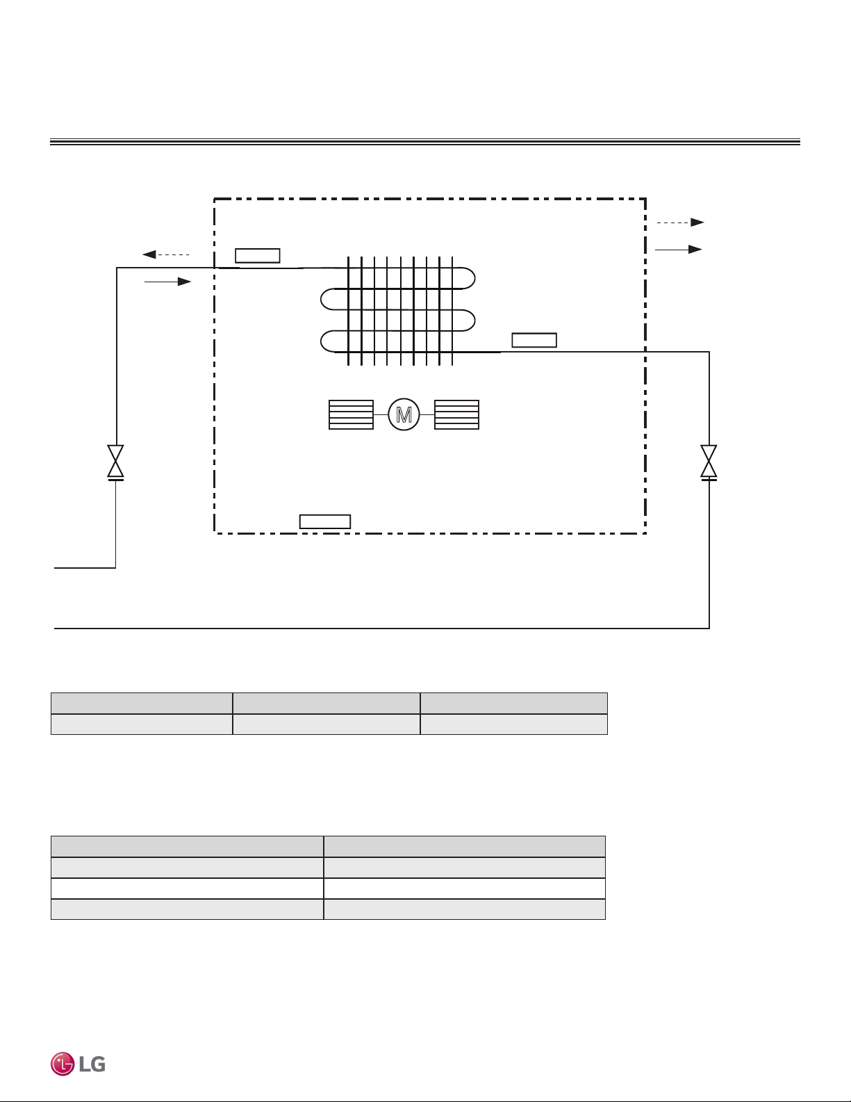
Figure 99: LDN097HV4 Refrigerant Flow Diagram.
Indoor Unit
: Cooling
: Heating
M
Sirocco Fan
Indoor Air
Temperature
Thermistor
Evaporator
Outlet
Temperature
Thermistor
Evaporator
Inlet
Temperature
Thermistor
MULTI
F
MAX
MULTI
F
DUCT (LOW STATIC) INDOOR UNITS
Refrigerant Flow Diagrams
Ceiling-Concealed Duct (Low Static)
Table 40: Multi F Ceiling-Concealed Duct (Low Static) LDN097HV4 Indoor Unit Refrigerant Pipe Connection Port Diameters.
Table 41: Multi F Ceiling-Concealed Duct (Low Static) LDN097HV4 Indoor Unit Thermistor Details.
Model No. Vapor (inch) Liquid (inch)
LDN097HV4 Ø3/8 Ø1/4
Description (Based on Cooling Mode) PCB Connector
Indoor Air Temperature Thermistor CN-ROOM
Evaporator Inlet Temperature Thermistor CN-PIPE/IN
Evaporator Outlet Temperature Thermistor CN-PIPE/OUT
Due to our policy of continuous product innovation, some specications may change without notication.
©LG Electronics U.S.A., Inc., Englewood Cliffs, NJ. All rights reserved. “LG” is a registered trademark of LG Corp.
DUCT (LOW STATIC) | 81
Page 82

DUCT (LOW STATIC) INDOOR UNITS
Indoor Unit
: Cooling
: Heating
MM
Sirocco Fan
Indoor Air
Temperature
Thermistor
Evaporator
Outlet
Temperature
Thermistor
Evaporator
Inlet
Temperature
Thermistor
MULTI
F
MAX
MULTI
F
Refrigerant Flow Diagrams
Figure 100:LDN127HV4 and LMDN186HV Refrigerant Flow Diagram.
Table 42: Multi F Ceiling-Concealed Duct (Low Static) LDN127HV4 and LMDN186HV Indoor Unit Refrigerant
Pipe Connection Port Diameters.
Model No. Vapor (inch) Liquid (inch)
LDN127HV4 Ø3/8
LMDN186HV Ø1/2
Multi F and Multi F MAX Indoor Unit Engineering Manual
Table 43: Multi F Ceiling-Concealed Duct (Low Static) LDN127HV4 and LMDN186HV Indoor Unit Thermistor Details.
Description (Based on Cooling Mode) PCB Connector
Indoor Air Temperature Thermistor CN-ROOM
Evaporator Inlet Temperature Thermistor CN-PIPE/IN
Evaporator Outlet Temperature Thermistor CN-PIPE/OUT
82 | DUCT (LOW STATIC)
Due to our policy of continuous product innovation, some specications may change without notication.
©LG Electronics U.S.A., Inc., Englewood Cliffs, NJ. All rights reserved. “LG” is a registered trademark of LG Corp.
Ø1/4
Page 83

DUCT (LOW STATIC) INDOOR UNITS
MULTI
F
MAX
MULTI
F
Wiring Diagram
Figure 101:Multi F Ceiling-Concealed Duct (Low Static) LDN097HV4, LDN127HV4, and LMDN186HV Indoor Units Wiring Diagram.
Ceiling-Concealed Duct (Low Static)
Due to our policy of continuous product innovation, some specications may change without notication.
©LG Electronics U.S.A., Inc., Englewood Cliffs, NJ. All rights reserved. “LG” is a registered trademark of LG Corp.
DUCT (LOW STATIC) | 83
Page 84

DUCT (LOW STATIC) INDOOR UNITS
WARNING
MULTI
F
MAX
MULTI
F
Factory Supplied Parts and Materials
Factory Supplied Parts
Table 44: Parts Table.
Part Quantity Image Part Quantity Image
Drain Hose One (1) Zip Ties Four (4)
Washers for
Metal Clamp Two (2)
Insulation for
Fittings
1
Simple Mode Controllers for the ceiling-concealed duct (low static) indoor units are also referenced by Model No. PQRCVCL0QW.
One (1) Set
For Vapor Piping For Liquid Piping
Hanging
Brackets
Simple
Controller
with Mode
Selection
(AKB72955816)
Eight (8)
One (1)
1
Factory Supplied Materials
• Owner’s Manual
• Installation Manual
Installation work must be performed by trained personnel and in accordance with national wiring standards and all local or other applicable codes.
Improper installation can result in re, electric shock, physical injury, or death.
Multi F and Multi F MAX Indoor Unit Engineering Manual
Required Tools
• Level
• Screwdriver
• Electric drill
• Hole core drill
• Flaring tool set
• Torque wrenches
• Hexagonal wrench
• Gas-leak detector
• Thermometer
Note:
Read all instructions before installing this product. Become familiar with the unit’s components and connections, and the order of installation. Incorrect
installation can degrade or prevent proper operation.
84 | DUCT (LOW STATIC)
Due to our policy of continuous product innovation, some specications may change without notication.
©LG Electronics U.S.A., Inc., Englewood Cliffs, NJ. All rights reserved. “LG” is a registered trademark of LG Corp.
Page 85

DUCT (LOW STATIC) INDOOR UNITS
Access Opening
(
23-5/8
x
23-5/8
)
Control box
H = ≤25/32
• "H" dimension is necessary to ensure a slope is included for
condensate drainage.
Side view
23-5/8
23-5/8
(Unit : Inch)
(Unit : Inch)
Top view
MULTI
F
MAX
MULTI
F
Installation and Best Layout Practices
Selecting the Best Location
Do’s
• Place the unit where air circulation will not be blocked.
• Place the unit where drainage can be obtained easily.
• Place the unit where noise prevention is taken into consideration.
• Ensure there is sufcient strength to bear the load of the indoor unit.
• Ensure there is sufficient maintenance space.
• Locate the indoor unit in a location that is level, and where it can be easily
connected to the outdoor unit / branch distribution unit.
Don’ts
• Do not install the unit near a heat or steam source, or where considerable
amounts of oil, iron powder, or flour are used.
• Do not install the unit where sulfuric acid and flammable or corrosive gases
are generated, vented into, or stored.
• Do not install the unit near high-frequency generators.
• Do not install the unit near a doorway.
The unit may be damaged, may malfunction, and / or will not operate
as designed if installed in any of the conditions listed.
Installing in an Area Exposed to Unconditioned Air
In some installation applications, areas(floors, walls) in some rooms may be exposed to unconditioned air (room may be above or next to an unheated garage
or storeroom). To countermeasure:
• Verify that carpet is or will be installed (carpet may increase the temperature
by three degrees).
• Add insulation between the floor joists.
• Install radiant heat or another type of heating system to the floor.
Figure 102:General Installation Guidelines.
Figure 103:Service / Access Panel Dimensions.
A (Min)
B (Min)
Ceiling-Concealed Duct (Low Static)
Installing in an Area with High Humidity Levels
If the environment is prone to humidity levels of 80% or more (near the ocean,
lakes, etc.) or where steam could collect in the plenum:
• Install additional insulation to the indoor unit (glass wool insulation >13/32
inches thick).
• Install additional insulation to the refrigerant piping (insulation >13/16 inches
thick).
• Seal all gaps between the indoor unit and the ceiling tiles (make the area air
tight) so that humidity does not transfer from the plenum to the conditioned
space. Also, add a ceiling grille for ventilation.
If the unit is installed near a body of water, certain components are at risk of being
corroded. Appropriate anti-corrosion methods should be taken for the unit and all
components.
Table 45:General Access Panel Dimensions.
Model / Capacity (Btu/h)
LDN097HV4 / 9,000
LDN127HV4 / 12,000
LMDN186HV / 18,000
Due to our policy of continuous product innovation, some specications may change without notication.
©LG Electronics U.S.A., Inc., Englewood Cliffs, NJ. All rights reserved. “LG” is a registered trademark of LG Corp.
Ceiling
Service Space
A
B
Dimensions (in.)
A B
31-1/2
31-1/2
DUCT (LOW STATIC) | 85
39-3/8
Page 86

Indoor Unit s
Air Filter
Air Outlet
Air Outlet
Air Filter
Back Panel
Back Panel
DUCT (LOW STATIC) INDOOR UNITS
C
E
G
D
F
I
A
J
B
H
Drainage hole
MULTI
F
MAX
MULTI
F
Installation and Best Layout Practices
Duct (Low Static) Indoor Units can be installed in two ways:
Figure 104:Air inlet from the back of the indoor
unit.
Table 46:Indoor Unit Bolt Location Dimensions.
Model / Capacity (Btu/h)
LDN097HV4 / 9,000 28-27/32 30-13/32
LDN127HV4 / 12,000
LMDN186HV / 18,000
36-23/32 38-9/32 33-27/32 35-7/16
Figure 105:Air inlet from the bottom of the
indoor unit.
A B C D E F G H I J
Table 47:Indoor Unit Bolt Locations.
Dimensions (in.)
24-23/32 27-9/16 1-13/32 7-15/32 25/32
25-31/32
27-9/16
6-3/32
Preparing the Installation Area and Hanging the Indoor Unit Frame
1. Select and mark the area for the suspension or console bolts
(use embedded inserts or anchor bolts in new buildings, and
hole-in-anchors in older buildings).
2. Drill the holes.
3. Add the set-anchor and the plate washer to the bolts (bolts
should be at least 13/32 inches in diameter), and then insert the
bolts into the installation area.
Figure 106:Preparing the Installation Area.
Figure 107:Console Bolt Options.
4. Add the plate washer, spring washer, and nut to secure the bolts
into the installation area.
5. Position the indoor unit installation plates onto the bolts. Secure
using nuts, plate washers, and spring washers. Adjust for level as
necessary.
Figure 108:Hanging the Indoor Unit.
Multi F and Multi F MAX Indoor Unit Engineering Manual
Install a canvas duct to the air outlet and air inlet so that vibration from the indoor unit does not carry
to the duct or ceiling. Also, add insulation to the interior of the duct, and apply anti-vibration to the
suspension bolts.
M10 Nut
M10 SP. washer
M10 washer
M10 washer
M10 SP. washer
M10 Nut
X 4
X 4
X 4
X 4
X 4
X 4
(Field
supplied)
(Field
supplied)
86 | DUCT (LOW STATIC)
• Unit must be installed correctly.
• Tighten the nuts and bolts to prevent the unit from falling.
Due to our policy of continuous product innovation, some specications may change without notication.
©LG Electronics U.S.A., Inc., Englewood Cliffs, NJ. All rights reserved. “LG” is a registered trademark of LG Corp.
Page 87
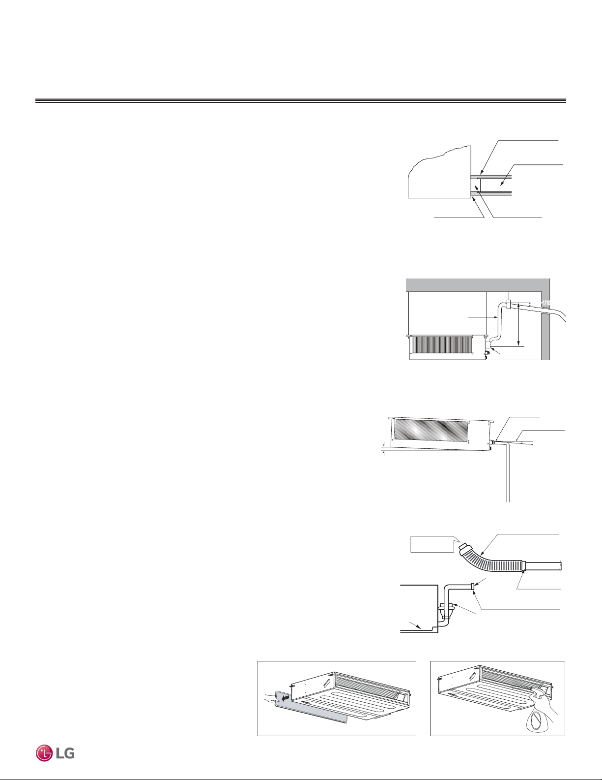
DUCT (LOW STATIC) INDOOR UNITS
Angle ≥ 1/50~1/100
Approx 3/32~5/32 inches
Drain hose
Insulation
≤27-9/16 inch
Drain Pipe
1/50~1/1001/50~1/100
Drain Pump
Pour Water
Drain Pump
Drain Pan
Flexible drain hose
(accessory)
Field-Installed
Drain Piping
Glue the Joint
Drain
Port
Drain Hose Connection
Use the clip (accessory)
Indoor Unit
MULTI
F
MAX
MULTI
F
Installation and Best Layout Practices
Installing the Drain System
• Drain piping must have downward gradient of at least 1/50 to 1/100; to prevent reverse flow,
slope should not be straight up and down.
• Do not damage the drain port on the indoor unit when connecting the field-supplied drain
piping.
• Drain piping specifications:
- Indoor Unit Drain Connection: 1-1/4 inch outside diameter.
- Field-Supplied Drain Piping: Polyvinyl chloride piping with 1-inch inside diameter and pipe
fittings.
Ducted (low static) indoor units have two options for condensate drainage: Using the factory-installed drain pump, or using a gravity drain.
Using the Drain Pump
• Maximum drain lift is 27-9/16 inches, therefore, the drain piping should be placed below
the maximum lift height.
• Field-installed drain piping must have downward gradient of at least 1/50 to 1/100; to
prevent reverse flow, slope should not be straight up and down.
Using the Gravity Drain
Field-drain piping must have downward gradient of at least 1/50 to 1/100; to prevent
reverse flow, slope should not be straight up and down.
Figure 109:Drain Connection.
(Field Supplied)
Drain Pipe
(Field Supplied)
Indoor Unit
Drain HoleClose Any Gaps
Figure 110:Indoor Unit Using Drain Pump.
Pump location may be different on the indoor unit.
Figure 111:Indoor Unit Using Gravity Drain.
Ceiling-Concealed Duct (Low Static)
Checking the Drain Pump
The unit uses a drain pump to remove condensate. The pump must be tested before the
system operates.
• Connect the flexible drain hose to the field-installed drain piping; leave it as is until the
test is complete.
• Pour water into the flexible drain hose and check for leaks.
• After power wiring installation is complete, operate the drain pump to see if it sounds
and functions properly.
• After the test is complete, connect the flexible drain hose to the indoor unit drain port.
Checking the Drainage System
1. Remove the air filter.
2. Check the drainage.
• Spray water on the evaporator.
• Verify that water flows through the indoor unit drain
hose without leaking.
Figure 112:Checking the Drain Pump.
Figure 113:Checking the Drainage System.
Due to our policy of continuous product innovation, some specications may change without notication.
©LG Electronics U.S.A., Inc., Englewood Cliffs, NJ. All rights reserved. “LG” is a registered trademark of LG Corp.
Pump location may be different
on the indoor unit.
DUCT (LOW STATIC) | 87
Page 88
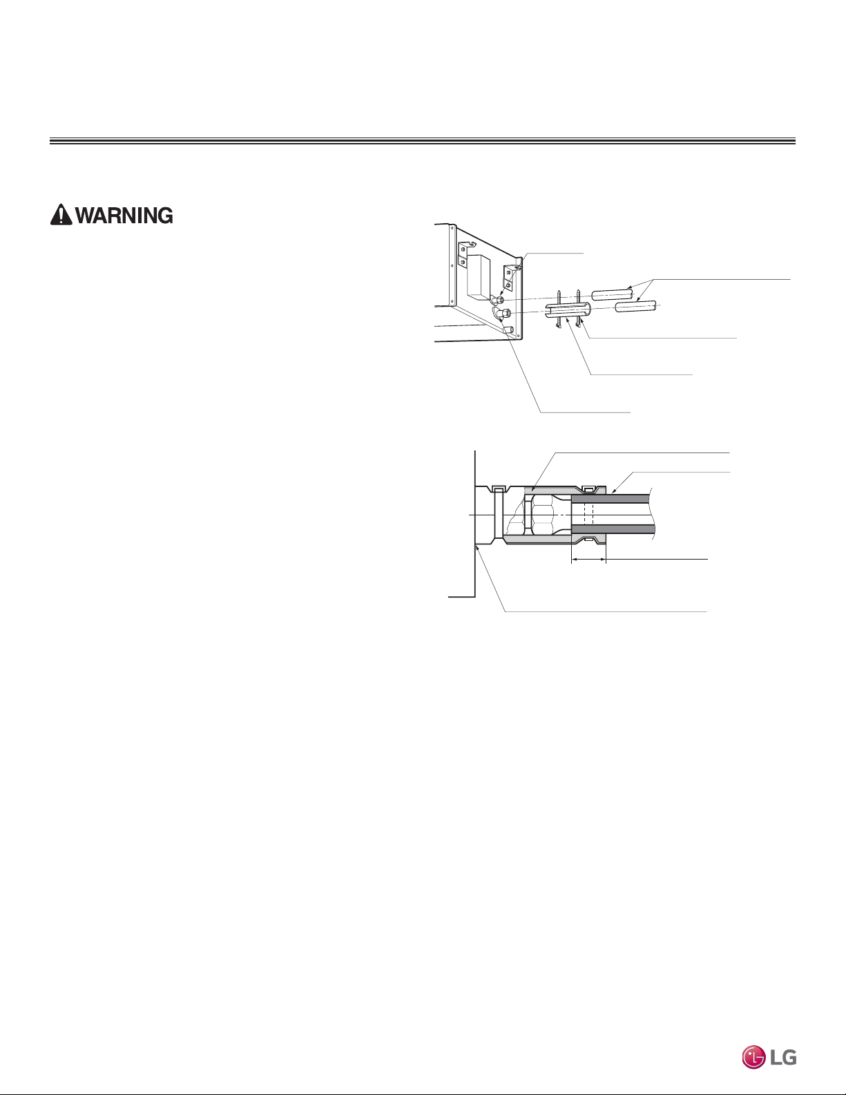
DUCT (LOW STATIC) INDOOR UNITS
MULTI
F
MAX
MULTI
F
Installation and Best Layout Practices
Insulating the Refrigerant and Drain Piping
Figure 114:Insulating the Piping.
Ensure all piping is insulated. Exposed piping can cause burns
if touched.
Refrigerant Piping Insulation
Field-installed vapor and liquid refrigerant piping lines must be
properly and completely covered in insulation (up to the indoor unit
piping connections). Any exposed piping may generate condensate
or will cause burns if touched. Insulation for this field-installed refrigerant piping must have a minimum heat resistance of 248°F.
Duct (low static) indoor units have been tested under and meet the
requirements of the “KS Conditions.” If the indoor unit is installed
and is operated at an extended period in a highly humid environment
(dew point temperature >73°F), however, condensate will form. To
prevent this phenomenon, install adiabatic glass wool insulation with
a thickness or 13/32 to 13/16 inches thick. Also, install glass wool
insulation on all indoor unit that are located in the ceiling plenum.
Drain Piping Insulation
Drain piping must have insulation a minimum of 7/32 inches thick.
Liquid Piping
Connection
Clamp for Insulation
(Field-Supplied)
Insulation
(Field-Supplied)
Vapor Piping Connection
Insulation for Refrigerant Piping
(Field-Supplied)
Ensure no gaps are present.
Insulation for Refrigerant Piping
(Field-Supplied)
Insulation for Field-Installed Piping
(Field-Supplied)
Overlap the Insulation at the
Connection
Multi F and Multi F MAX Indoor Unit Engineering Manual
88 | DUCT (LOW STATIC)
Due to our policy of continuous product innovation, some specications may change without notication.
©LG Electronics U.S.A., Inc., Englewood Cliffs, NJ. All rights reserved. “LG” is a registered trademark of LG Corp.
Page 89

DUCT (LOW STATIC) INDOOR UNITS
Indoor Unit Terminal Block
1(L) 2(N)
GND
3
Outdoor Unit Terminal Block or
Branch Distribution Unit Terminal Block
(Multi F MAX Systems Only)
GND
GRN /
YLW
BR
BL
RD
3 or S
Lock nut
Conduit
mounting
plate
Conduit
MULTI
F
MAX
MULTI
F
Installation and Best Layout Practices
Power Wiring / Communications Cable Guidelines
• Follow manufacturer’s circuit diagrams in the technical manuals.
• Confirm power source specifications.
• Confirm that the electrical capacity is sufficient.
• Starting current must be maintained ±10 percent of the rated current marked on the outdoor unit name plate.
• Confirm cable thickness specifications.
• It is recommended that a circuit breaker is installed, especially if conditions could become wet or moist.
• Include a disconnect in the power wiring system, add an air gap contact separation of at least 1/8 inch in each active (phase) conductor.
• Loose wiring may cause unit to malfunction, overheat, and catch fire, resulting in severe injury or death.
Note:
• Terminal screws may become loose during transport. Properly tighten the terminal connections during installation.
A voltage drop may cause the following problems:
• Magnetic switch vibration, fuse breaks, or disturbance to the normal function of an overload protection device.
• Compressor will not receive the proper starting current.
Connecting the Power Wiring and Communications Cable
1. Insert the power wiring / communications cable from the outdoor unit or branch distribution unit (Multi F MAX systems only)
through the side of the indoor unit. Pass the wiring through the
designated access holes to prevent damage. To prevent electromagnetic interference and product malfunction, leave a space
between the power wiring and communications cable outside of
the indoor unit.
2. Connect each wire to its appropriate terminal on the indoor unit
control board. Verify that the color and terminal numbers from
the outdoor unit or branch distribution unit (Multi F MAX systems
only) wiring match the color and terminal numbers on the indoor
unit.
3. Secure the power wiring / communications cable with the cable
restraint.
Figure 115:Indoor Unit to Outdoor Unit / Branch Distribution Unit
(Multi F MAX systems only) Power Wiring / Communications Cable
Connections.
Ceiling-Concealed Duct (Low Static)
4. Screw the steel clamp to the inside of the control panel.
• Place the wiring / cables in the clamp and tighten the plastic clamp to an open surface of the control panel.
• When clamping, do not apply force to the wiring connections.
• Neatly arrange the wiring, do not catch the wiring in the electric box cover, and ensure the cover firmly closes.
5. Fill in any gaps around the wiring access hole with sealant to prevent foreign particles from entering the indoor unit.
Using a Conduit
1. Remove the rubber stopper on the indoor unit. Pass the power
wiring / communications cable through the conduit, the conduit
mounting plate, and to the control panel of the indoor unit.
2. Connect the power wiring / communications cable to the indoor
unit terminal block.
3. Screw the conduit mounting plate to the indoor unit.
4. Tighten the conduit and the conduit mounting plate together.
Due to our policy of continuous product innovation, some specications may change without notication.
©LG Electronics U.S.A., Inc., Englewood Cliffs, NJ. All rights reserved. “LG” is a registered trademark of LG Corp.
Figure 116:Exterior View of Conduit Installation.
DUCT (LOW STATIC) | 89
Page 90

Indoor Unit Terminal Block
1(L) 2(N)
GND
3
Outdoor Unit Terminal Block or
Branch Distribution Unit Terminal Block
(Multi F MAX Systems Only)
GND
GRN /
YLW
BR
BL
RD
3 or S
CN-REMO
YL
RD BK
Comm.
12V
Power
Ground
DUCT (LOW STATIC) INDOOR UNITS
TEMP
FA N
SPEED
OPER
MODE
Operation Display
Panel
Temperature Control
Button
Fan Speed Button
On/Off Button
Mode Selection
Check Button
Verify the connectors are properly inserted.
C/BOX Cable (Plug type)
Extension cable
To Indoor Unit
CN-REMO
Terminal
TEMP
FAN
SPEED
OPER
MODE
MULTI
F
MAX
MULTI
F
Installation and Best Layout Practices
Controller Options
Ceiling-concealed duct (low static) indoor units include an LG-supplied wired controller
(AKB72955816)1, but other optional LG-supplied wired controllers are available. The
wireless handheld controller (Model No. PQWRHQ0FDB) is also an optional
accessory with use of the wired controller.
• Operation Display Panel: Displays operation conditions.
• Temperature Control Button: Sets desired temperature.
• Fan Speed Button: Sets desired fan speed.
• On / Off Button: Turns system operation on and off.
• Mode Selection Check Button: Selects the operation mode: Cooling, Heating, Auto,
Dry (Dehumidification), or Fan.
Each function will display on the LED for about three (3) seconds when the power is rst cycled on.
1
Simple Mode Controllers for the ceiling-concealed duct (low static) indoor units are also referenced by Model No. PQRCVCL0QW.
Wired Controller Connections
Controllers can connect to the indoor unit in one of two different
ways.
1. LG Wired Remote Extension Cable with Molex plug (PZCWRC1;
sold separately) that connects to the CN-REMO terminal on the
indoor unit PCB.
Figure 118:PZCWRC1 LG Wired Remote Extension Cable.
Wired Controller
Figure 117:AKB729558161 Wired Controller.
2. Field-supplied controller cable that connects to the indoor unit
terminal block (must be at least UL2547 or UL1007, 22 AWG,
two-core, one-shield core, at least FT-6 rated if local electric and
building codes require plenum cable usage).
Multi F and Multi F MAX Indoor Unit Engineering Manual
When using eld-supplied controller cable, make sure to connect
the yellow to yellow (communications wire), red to red (12V power
wire), and black to black (ground wire) terminals from the remote
controller to the indoor unit terminal blocks.
90 | DUCT (LOW STATIC)
©LG Electronics U.S.A., Inc., Englewood Cliffs, NJ. All rights reserved. “LG” is a registered trademark of LG Corp.
Due to our policy of continuous product innovation, some specications may change without notication.
Figure 119:Wired Controller Connections on the Indoor Unit
Terminal Block.
Page 91
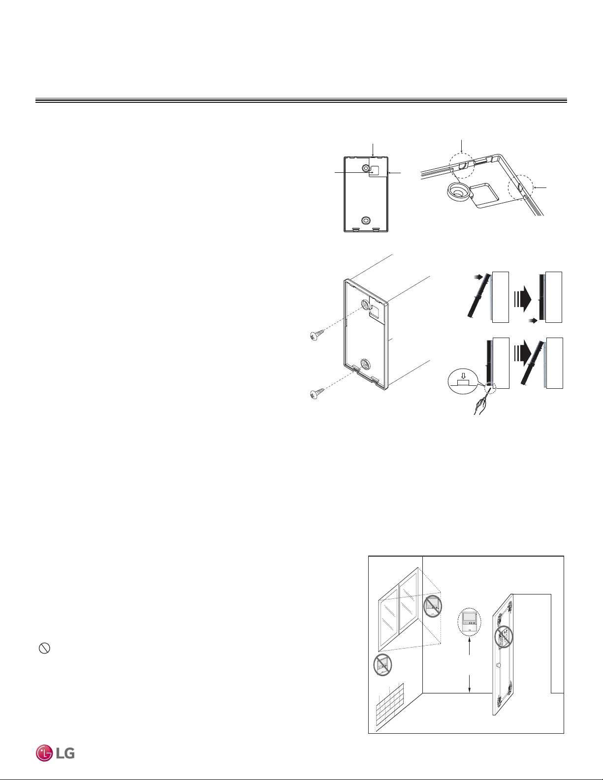
DUCT (LOW STATIC) INDOOR UNITS
Top
Wall Wa ll
Wall Wall
Installing the Controller
Removing the Controller
4 to 5 feet
above the floor
NO
NO
NO
YES
Remote Controller
TEMP
Remote Controller
TEMP
Re
m
ot
e
C
o
n
t
r
ol
l
er
TEMP
MULTI
F
MAX
MULTI
F
Installation and Best Layout Practices
Hanging the Wired Controller
1. The controller wiring / cable can be installed in one of three direc-
tions: top, back, or on the right side. If top or right side installation
is desired, remove cable guide grooves on the controller, and
then position wiring / cable on applicable side.
2. Choose and mark the area of installation, and then screw the wall
plate into place (using the provided parts). Install the controller
wall plate to fit the electrical box if one is present. Ensure that no
gaps exist between the wall plate and the wall itself.
3. Arrange wiring / cables so as not to interfere with the controller
circuitry. Position the wired controller on the wall plate. Snap into
place by pressing the bottom part of the wired controller onto
the wall plate. Make sure that no gaps exist between the wired
controller and the wall plate on all sides.
4. To remove wired controller from the wall plate, insert a screw-
driver into the two holes at the bottom. Twist screwdriver to
release controller. Do not damage the controller components
when removing.
Figure 120:Removing the Cable Guide Grooves.
Top
Back
Figure 121:Attaching the Wall Plate.
Right
Side
Figure 122: Installing / Removing
the Controller.
Right
Side
Ceiling-Concealed Duct (Low Static)
Assigning the Thermistor for Temperature Detection
Each indoor unit includes a return air thermistor assigned to sense the temperature. If a wired controller is installed, there is a choice of
sensing temperature with either the indoor unit return air thermistor or the thermistor in the wired controller. It is also an option to set both
thermistors to sense temperature so that indoor unit bases its operation on the first thermistor to reach the designated temperature differential. For applicable indoor units, an optional Remote Temperature Sensor can be used in lieu of the return air thermistor—either alone or in
conjunction with a wired controller thermistor as previously described.
Figure 123:Proper Location for the Wired Controller.
Wired Controller Placement
Wired controllers include a sensor to detect room temperature. To maintain comfort
levels in the conditioned space, the wired controller must be installed in a location
away from direct sunlight, high humidity, and where it could be directly exposed to
cold air. Controller must be installed four (4) to five (5) feet above the floor where its
LED display can be read easily, in an area with good air circulation, and where it can
detect an average room temperature.
Do not install the wired controller near or in:
• Drafts or dead spots behind doors and in corners
• Hot or cold air from ducts
• Radiant heat from the sun or appliances
• Concealed pipes and chimneys
• An area where temperatures are uncontrolled, such as an outside wall
Due to our policy of continuous product innovation, some specications may change without notication.
©LG Electronics U.S.A., Inc., Englewood Cliffs, NJ. All rights reserved. “LG” is a registered trademark of LG Corp.
DUCT (LOW STATIC) | 91
Page 92

DUCT (LOW STATIC) INDOOR UNITS
TEM P
FA N
SPEED
OPER
MODE
MULTI
F
MAX
MULTI
F
Installation and Best Layout Practices
External Static Pressure Control
To provide a required air flow rate that accounts for the external static pressure change, follow the steps
below.
1. To access system installer setting mode, press and hold the temperature increase and mode selection
buttons simultaneously for approximately three (3) seconds. Choose setting code value “06” by pressing the mode selection button.
2. Use the temperature increase and decrease buttons to select the
desired setting value.
Setting Values
01 : V-H
02 : F-H
03 : V-L
04 : F-L
3. Press the on / off button to save the established settings.
4. To deactivate system installer setting mode after the settings have been established, press and hold
the temperature increase and mode selection check buttons simultaneously for approximately three
(3) seconds. If a button is not pressed for more than 25 seconds, the system installer setting mode
will automatically deactivate.
Table 48:Static Pressure Setting Table.
Pressure Selection
01 V-H Variable High
02 F-H Fixed High
03 V-L Variable Low
04 F-L Fixed Low
Function
Zone State External Static Pressure Standard Value
Figure 124:Select Code and
Set Value.
Code
Set Value
Figure 125:Controller External
Static Pressure Setting Display.
• Select the position after verifying duct work and the external static pressure of the indoor unit.
• Factory set to pressure selection F-H.
Multi F and Multi F MAX Indoor Unit Engineering Manual
92 | DUCT (LOW STATIC)
Due to our policy of continuous product innovation, some specications may change without notication.
©LG Electronics U.S.A., Inc., Englewood Cliffs, NJ. All rights reserved. “LG” is a registered trademark of LG Corp.
Page 93

DUCT (LOW STATIC) INDOOR UNITS
TEMP
FA N
SPEED
OPER
MODE
MULTI
F
MAX
MULTI
F
Installation and Best Layout Practices
Assigning Air Flow
To assign an air flow for each fan speed, follow the steps below.
1. To access system installer setting mode, press and hold the temperature increase and mode selection
buttons simultaneously for approximately three (3) seconds. Choose setting code value “03” by pressing the mode selection button.
2. Use the fan speed button to select the desired fan speed. ( Lo→Med→Hi will display on the LED).
3. Use the temperature increase and decrease buttons to select the desired external static
pressure setting value (thereby assigning the respective airflow). External static pressure value range:
0~255; the value will display near the lower right corner of the LED.
4. Press the on / off button to save the established settings.
5. To deactivate system installer setting mode after the settings have been established, press and hold
the temperature increase and mode selection check buttons simultaneously for approximately three
(3) seconds. If a button is not pressed for more than 25 seconds, the system installer setting mode
will automatically deactivate.
• A certified technician must set the external static pressure value(s). If the external static pressure is set incorrectly, the system may
malfunction.
• Do not alter the external static pressure value that corresponds to each air flow level.
• External static pressure value can vary depending on the indoor unit.
• If by pressing the fan speed button during external static pressure setup, the fan speed is raised to the next level, the air flow value of
the previous fan speed will be maintained (external static pressure setting value is saved).
Figure 126:Controller External
Static Pressure Setting Display.
Ceiling-Concealed Duct (Low Static)
Due to our policy of continuous product innovation, some specications may change without notication.
©LG Electronics U.S.A., Inc., Englewood Cliffs, NJ. All rights reserved. “LG” is a registered trademark of LG Corp.
DUCT (LOW STATIC) | 93
Page 94

CEILING-CONCEALED
DUCT (HIGH STATIC)
INDOOR UNIT DATA
“Mechanical Specifications” on page 95
“General Data / Specifications” on page 96
“Dimensions” on page 97
“Cooling Capacity Table” on page 98
“Heating Capacity Table” on page 99
“External Static Pressure” on page 100
“Acoustic Data” on page 100
“Refrigerant Flow Diagrams” on page 101
“Wiring Diagram” on page 102
“Factory Supplied Parts and Materials” on page 103
“Installation and Best Layout Practices” on page 104
Page 95

MULTI
F
MAX
MULTI
F
DUCT (HIGH STATIC) INDOOR UNITS
Mechanical Specications and Features
Ceiling-Concealed Duct (High Static)
Indoor Unit
General
All LG indoor units are factory assembled, wired, piped, and provided
with a control circuit board, fan, and motor. Ceiling-Concealed Duct
(High Static) units are designed for high-speed air volume against an
external static pressure up to 0.78″WG for the 24,000 Btu/h model;
up to 0.55″WG for the 36,000 Btu/h model.
Coil
Indoor unit coils are factory built and are comprised of aluminum fins
mechanically bonded to copper tubing. Each unit has two rows of
coils, which are pressure tested at the factory. Each unit is provided
with a factory installed condensate drain pan below the coil.
Refrigerant System
System is designed for use with R410A refrigerant. The refrigeration
circuit is pressure-tested at the factory and shipped with a holding
charge of helium gas. Refrigerant pipe connections are 45° flare,
and all refrigerant lines from the outdoor unit to the indoor units must
be field insulated.
Electrical
Each indoor unit is designed to operate using 208–230/60/1 power
with voltage variances of ±10%.
Casing
The casing is designed to mount fully concealed above a finished
ceiling. Casing is manufactured of galvanized steel plate. Cold surfaces of the unit are covered internally with a coated polystyrene insulating material, and covered externally with sheet insulation made
of ethylene propylene diene monomer (M-Class) (EPDM). External
insulation is plenum rated and conforms to ASTM Standard D-1418.
Hanger brackets are included on the casing to support the weight on
four corners. Unit has a front horizontal supply air discharge outlet,
and one dedicated rear horizontal return air inlet.
Fan Assembly and Control
The units have two direct-drive, Sirocco fans made of high strength
ABS GP-2200 polymeric resin that are statically and dynamically
balanced. The fans are mounted on a common brushless digitally
controlled (BLDC) motor with permanently lubricated and sealed
ball bearings. The fan / motor assembly is mounted on vibration-attenuating rubber grommets. Fan speed is controlled using a microprocessor-based direct digital control algorithm. The indoor fan has
Low, Med, High, and Auto settings for Cooling mode; and has Low,
Figure 127: Ceiling-Concealed Duct (High Static) Indoor Unit.
Med, High, and Auto settings for Heating mode. Each of the settings
can be field-adjusted from the factory setting (RPM / ESP). The Auto
setting adjusts the fan speed based on the difference between the
controller setpoint and space temperature.
Air Filter
Return air is filtered with a factory-supplied, removable, washable
filter accessible from the rear of the indoor unit. High efficiency air
filter options include a return filter box and an LG / Dynamic supplied
air cleaner (both sold separately).
Microprocessor Control
The unit is provided with an integrated control panel to communicate
with the outdoor unit. All unit operation parameters are stored in nonvolatile memory resident on the unit microprocessor. The microprocessor controls space temperature through using the value provided
by the temperature sensor within the indoor unit. The microprocessor
control will activate indoor unit operation when the indoor room temperature falls below or rises above a setpoint temperature, at which
point, a signal is sent to the outdoor unit to begin the appropriate
mode. The microprocessor will also provide self-diagnostics and auto
restart functions. A field-supplied four-wire power / communications
cable must be installed to connect the indoor unit(s) to the outdoor
unit.
Controls
The indoor unit is supplied with an LG wired controller. Communication between the indoor units and the outdoor unit is accomplished
through 18 AWG, four-core, stranded and shielded power / communication cable.
Condensate Lift/Pump
The indoor unit is provided with a factory installed and wired internal
condensate lift/pump capable of providing a minimum 27.5 inch lift
from the bottom surface of the unit. Drain pump has a safety switch
to shut off the indoor unit if the condensate rises too high in the drain
pan.
Ceiling-Concealed Duct (High Static)
Features
• Inverter (Variable speed fan)
• Internal drain pump
• Control lock function
• Auto operation
• Auto restart operation
• Dehumidifying function
• Two thermistor control
• External static pressure control
Due to our policy of continuous product innovation, some specications may change without notication.
©LG Electronics U.S.A., Inc., Englewood Cliffs, NJ. All rights reserved. “LG” is a registered trademark of LG Corp.
• Group control
• Self-diagnostics function
• Wired thermostat included
DUCT (HIGH STATIC) | 95
Page 96
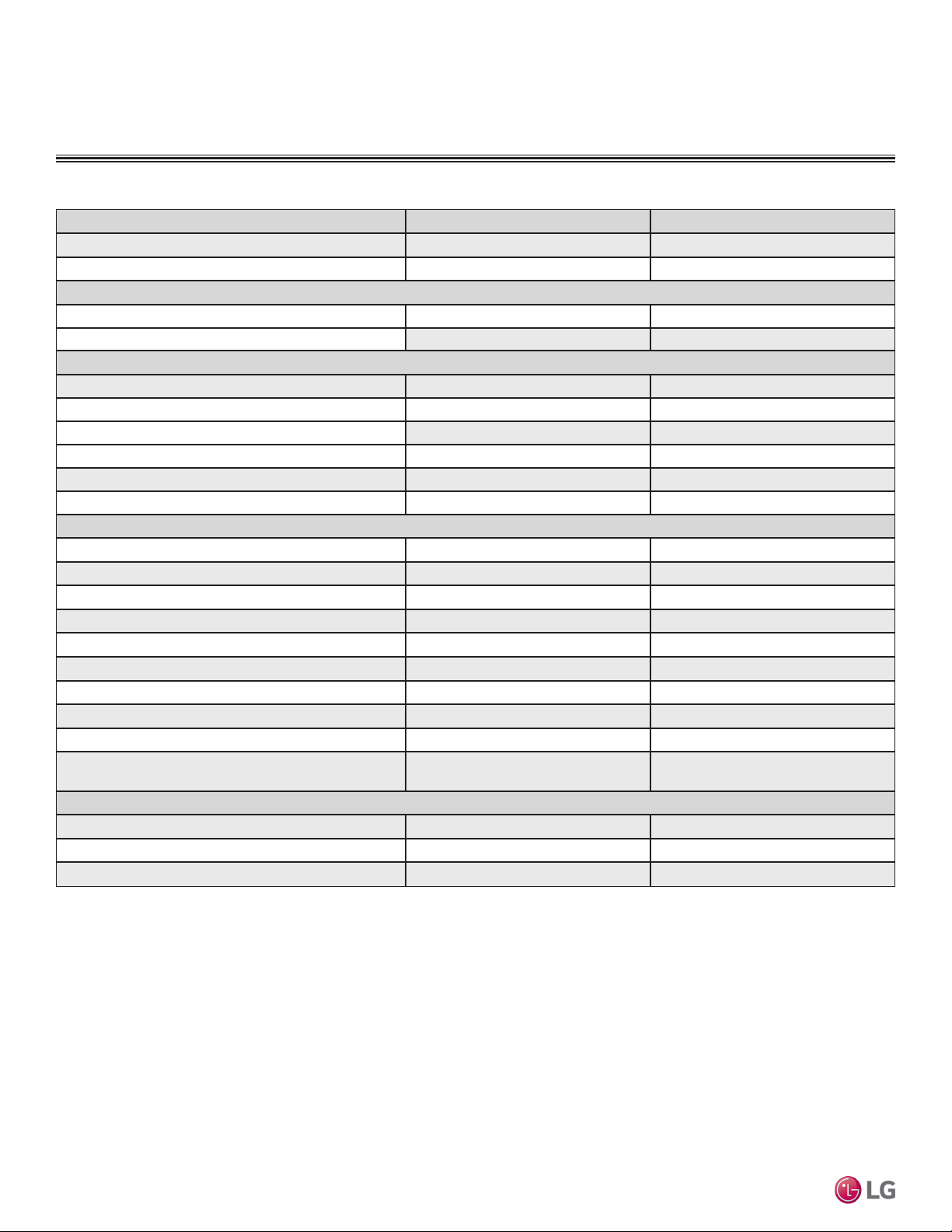
MULTI
F
MAX
MULTI
F
DUCT (HIGH STATIC) INDOOR UNITS
General Data / Specications
Table 49: Multi F Ceiling-Concealed High-Static Ducted Indoor Unit General Data.
Model Name LMHN240HV LMHN360HV
Nominal Cooling Capacity (Btu/h)
Nominal Heating Capacity (Btu/h)
1
1
Operating Range
Cooling (°F WB)
Heating (°F DB)
Fan
Type
Motor Output (W) x Qty.
Motor/Drive
Brushless Digitally Controlled / Direct Brushless Digitally Controlled / Direct
Factory Set Airflow Rate CFM (H/M/L)
Factory Set External Static Pressure (in. wg)
Maximum External Static Pressure (in. wg)
Unit Data
Refrigerant Type
2
Refrigerant Control
Power Supply V, Ø, Hz3
Rated Amps (A)
Sound Pressure Level (Standard Mode) ±3 dB(A) H/M/L)4
Dimensions (W x H x D, in.)
46-17/32 x 11-23/32 x 17-23/32 46-17/32 x 11-23/32 x 17-23/32
Net Unit Weight (lbs.)
Shipping Weight (lbs.)
Power Wiring / Communications Cable (No. x AWG)5
Heat Exchanger
(Row x Column x Fin / inch) x Number
Piping
Liquid (in.)
Vapor (in.)
Drain O.D. / I.D. (in.)
Multi F and Multi F MAX Indoor Unit Engineering Manual
1
Nominal capacity is rated 0 ft. above sea level with corresponding refrigerant piping length in
accordance with standard length of each outdoor unit and a 0 ft. level difference between outdoor and
indoor units. All capacities are net with a combination ratio between 95 – 105%.
Nominal cooling capacity rating obtained with air entering the indoor unit at 80ºF dry bulb (DB) and 67ºF
wet bulb (WB) and outdoor ambient conditions of 95ºF dry bulb (DB) and 75ºF wet bulb (WB).
Nominal heating capacity rating obtained with air entering the indoor unit at 70ºF dry bulb (DB) and 60ºF
wet bulb (WB) and outdoor ambient conditions of 47ºF dry bulb (DB) and 43ºF wet bulb (WB).
2
This unit comes with a dry helium charge.
24,000 36,000
27,000 40,000
57-77 57-77
59-81 59-81
Sirocco Sirocco
154 x 1 350 x 1
688 / 618 / 530 1,130 / 953 / 706
0.39 0.39
0.78 0.55
R410A R410A
EEV EEV
208-230, 1, 60 208-230, 1, 60
0.9 1.4
37 / 36 / 35 44 / 42 / 40
80 91
91 101
4 x 18 4 x 18
(2 x 12 x 21) x 1 (3 x 12 x 21) x 1
1/4 3/8
1/2 5/8
1-1/4, 1 1-1/4, 1
3
Acceptable operating voltage: 187V-253V.
4
Sound pressure levels are tested in an anechoic chamber under ISO Standard 3745 and are the
same in both cooling and heating mode. These values can increase due to ambient conditions during
operation.
5
All power wiring / communications cable to the IDUs be minimum 18 AWG, 4-conductor, stranded,
shielded or unshielded (if shielded, must be grounded to chassis at ODU only) and must comply with
applicable local and national codes.
96 | DUCT (HIGH STATIC)
Due to our policy of continuous product innovation, some specications may change without notication.
©LG Electronics U.S.A., Inc., Englewood Cliffs, NJ. All rights reserved. “LG” is a registered trademark of LG Corp.
Page 97

MULTI
F
MAX
MULTI
F
DUCT (HIGH STATIC) INDOOR UNITS
Figure 128: LMHN240HV and LMHN360HV Dimensions.
Dimensions
Ceiling-Concealed Duct (High Static)
Due to our policy of continuous product innovation, some specications may change without notication.
©LG Electronics U.S.A., Inc., Englewood Cliffs, NJ. All rights reserved. “LG” is a registered trademark of LG Corp.
DUCT (HIGH STATIC) | 97
Page 98

MULTI
F
MAX
MULTI
F
DUCT (HIGH STATIC) INDOOR UNITS
Cooling Capacity Table
Table 50:Multi F Ceiling-Concealed Duct (High Static) Indoor Units Cooling Capacity Table.
Model No. /
Nominal Capacity
of Indoor Unit
(Btu/h)
LMHN240HV
24,000
LMHN360HV
36,000
Multi F and Multi F MAX Indoor Unit Engineering Manual
TC = Total Capacity (kBtu/h).
SHC: Sensible Heat Capacity (kBtu/h).
Nominal capacity as rated 0 ft. above sea level and a 0 ft. level difference between outdoor and indoor units. Corresponding refrigerant piping length is accordance with standard length of each outdoor unit.
Nominal cooling capacity rating obtained with air entering the indoor unit at 80ºF dry bulb (DB) and 67ºF wet bulb (WB), and outdoor ambient conditions of 95ºF dry bulb (DB) and 75ºF wet bulb (WB).
The shaded table columns and rows indicate reference data. When operating at this temperature, these values can be different if the system is not running consistently.
Outdoor Air
Temp.
(°F DB)
14 23.53 17.66 24.99 18.66 26.45 18.07 27.50 18.45 29.37 18.60 30.83 18.95
20 23.51 17.80 24.97 18.80 26.43 18.21 27.48 18.59 29.35 18.75 30.81 19.10
25 23.49 17.94 24.95 18.95 26.41 18.35 27.46 18.73 29.33 18.89 30.79 19.25
30 23.47 18.08 24.93 19.09 26.39 18.49 27.44 18.88 29.30 19.04 30.76 19.40
35 23.46 18.21 24.91 19.24 26.37 18.63 27.42 19.02 29.28 19.18 30.74 19.54
40 23.44 18.35 24.89 19.38 26.35 18.77 27.40 19.16 29.26 19.33 30.72 19.69
45 23.42 18.49 24.87 19.53 26.33 18.91 27.38 19.31 29.24 19.47 30.69 19.84
50 23.40 18.62 24.85 19.67 26.31 19.05 27.36 19.45 29.21 19.61 30.67 19.99
55 23.38 18.76 24.84 19.82 26.29 19.19 27.34 19.59 29.19 19.76 30.64 20.13
60 23.37 18.90 24.82 19.96 26.27 19.33 27.32 19.73 29.17 19.90 30.62 20.28
65 23.35 19.03 24.80 20.10 26.25 19.47 27.29 19.88 29.15 20.04 30.60 20.42
70 23.33 19.17 24.78 20.25 26.23 19.61 27.27 20.02 29.13 20.19 30.57 20.57
75 22.77 18.85 24.21 19.94 25.66 19.33 26.70 19.75 28.55 19.94 29.99 20.34
80 22.21 18.53 23.65 19.63 25.09 19.05 26.13 19.48 27.97 19.69 29.42 20.10
85 21.65 18.19 23.09 19.30 24.53 18.75 25.57 19.19 27.40 19.43 28.84 19.84
90 21.09 17.85 22.53 18.96 23.96 18.45 25.00 18.90 26.83 19.15 28.27 19.59
95 20.49 17.66 21.92 18.79 23.35 18.31 24.00 18.48 26.20 19.05 27.63 19.50
100 19.99 17.19 21.42 18.31 22.85 17.87 23.69 18.19 25.70 18.64 27.13 19.10
105 19.49 16.71 20.92 17.84 22.35 17.43 23.38 17.91 25.20 18.23 26.63 18.70
110 18.99 16.14 20.42 17.26 21.85 16.90 22.88 17.37 24.70 17.71 26.13 18.19
115 18.49 15.66 19.92 16.78 21.35 16.45 22.38 16.93 24.20 17.29 25.63 17.77
118 18.19 15.55 19.62 16.68 21.05 16.36 22.08 16.86 23.90 17.23 25.33 17.72
122 18.10 15.51 19.52 16.64 20.95 16.34 21.98 16.83 23.81 17.21 25.23 17.71
14 35.29 25.46 37.48 26.90 39.67 26.04 41.26 26.59 44.06 26.81 46.25 27.32
20 35.26 25.66 37.45 27.11 39.64 26.25 41.23 26.80 44.02 27.02 46.21 27.54
25 35.24 25.86 37.43 27.32 39.61 26.45 41.19 27.01 43.99 27.23 46.18 27.75
30 35.21 26.06 37.40 27.53 39.58 26.65 41.16 27.21 43.96 27.44 46.14 27.96
35 35.18 26.25 37.37 27.73 39.55 26.85 41.13 27.42 43.92 27.65 46.11 28.17
40 35.16 26.45 37.34 27.94 39.52 27.06 41.10 27.63 43.89 27.86 46.07 28.39
45 35.13 26.65 37.31 28.15 39.49 27.26 41.07 27.83 43.86 28.07 46.04 28.60
50 35.10 26.85 37.28 28.36 39.46 27.46 41.04 28.04 43.82 28.27 46.00 28.81
55 35.08 27.04 37.25 28.57 39.43 27.66 41.01 28.24 43.79 28.48 45.97 29.02
60 35.05 27.24 37.23 28.78 39.40 27.86 40.97 28.45 43.76 28.69 45.93 29.23
65 35.02 27.44 37.20 28.98 39.37 28.06 40.94 28.65 43.72 28.90 45.90 29.44
70 34.99 27.63 37.17 29.19 39.34 28.26 40.91 28.86 43.69 29.10 45.86 29.65
75 34.15 27.18 36.32 28.75 38.49 27.87 40.05 28.47 42.82 28.75 44.99 29.32
80 33.31 26.71 35.47 28.29 37.64 27.46 39.20 28.08 41.96 28.39 44.12 28.97
85 32.48 26.23 34.63 27.82 36.79 27.03 38.35 27.66 41.10 28.00 43.26 28.61
90 31.64 25.73 33.79 27.33 35.94 26.59 37.50 27.24 40.25 27.61 42.40 28.23
95 30.74 25.46 32.88 27.09 35.02 26.39 36.00 26.64 39.30 27.46 41.44 28.11
100 29.99 24.78 32.13 26.40 34.27 25.76 35.53 26.23 38.55 26.87 40.69 27.53
105 29.24 24.10 31.38 25.72 33.52 25.13 35.07 25.82 37.80 26.28 39.94 26.96
110 28.49 23.27 30.63 24.89 32.77 24.36 34.32 25.04 37.05 25.54 39.20 26.22
115 27.74 22.58 29.88 24.19 32.02 23.71 33.57 24.41 36.31 24.93 38.45 25.62
118 27.29 22.41 29.43 24.04 31.57 23.59 33.12 24.30 35.86 24.84 38.00 25.55
122 27.14 22.36 29.28 23.99 31.43 23.55 32.97 24.26 35.71 24.81 37.85 25.53
68 / 57 73 / 61 77 / 64 80 / 67 86 / 72 90 / 75
TC SHC TC SHC TC SHC TC SHC TC SHC TC SHC
Indoor Air Temp. °F DB / °F WB
98 | DUCT (HIGH STATIC)
Due to our policy of continuous product innovation, some specications may change without notication.
©LG Electronics U.S.A., Inc., Englewood Cliffs, NJ. All rights reserved. “LG” is a registered trademark of LG Corp.
Page 99

MULTI
F
MAX
MULTI
F
DUCT (HIGH STATIC) INDOOR UNITS
Heating Capacity Table
Table 51:Multi F Ceiling-Concealed Duct (High Static) Indoor Units Heating Capacity Table.
Model No. /
Nominal Capacity
of Indoor Unit
(Btu/h)
LMHN240HV
24,000
LMHN360HV
36,000
TC = Total Capacity (kBtu/h).
Nominal capacity as rated 0 ft. above sea level and a 0 ft. level difference between outdoor and indoor units. Corresponding refrigerant piping length is accordance with standard length of each outdoor unit.
Nominal heating capacity rating obtained with air entering the indoor unit at 70ºF dry bulb (DB) and 60ºF wet bulb (WB), and outdoor ambient conditions of 47ºF dry bulb (DB) and 43ºF wet bulb (WB).
Outdoor Air Temp. Indoor Air Temp. °F DB
°F DB °F WB
0 -0.4 13.89 13.70 13.57 13.50 13.30 12.72
5 4.5 15.65 15.46 15.33 15.26 15.07 14.48
10 9 17.41 17.22 17.09 17.02 16.83 16.24
17 15 19.76 19.57 19.43 19.37 19.17 18.55
20 19 20.64 20.45 20.32 20.25 20.05 19.37
25 23 22.11 21.91 21.78 21.72 21.52 20.74
30 28 23.38 23.18 23.05 22.99 22.79 22.11
35 32 24.65 24.46 24.33 24.26 24.07 23.48
40 36 25.79 25.60 25.47 25.40 25.21 24.62
45 41 26.93 26.74 26.61 26.54 26.35 25.76
47 43 27.39 27.20 27.07 27.00 26.80 26.22
50 46 27.83 27.64 27.51 27.44 27.24 26.58
55 51 28.57 28.37 28.24 28.17 27.98 27.20
60 56 28.57 28.37 28.24 28.17 27.98 27.32
63 59 28.57 28.37 28.24 28.17 27.98 27.39
68 64 28.57 28.37 28.24 28.17 27.98 27.51
0 -0.4 20.58 20.29 20.10 20.00 19.71 18.84
5 4.5 23.19 22.90 22.71 22.61 22.32 21.45
10 9 25.80 25.51 25.31 25.22 24.93 24.06
17 15 29.28 28.99 28.79 28.70 28.41 27.48
20 19 30.58 30.29 30.10 30.00 29.71 28.70
25 23 32.75 32.46 32.27 32.17 31.88 30.72
30 28 34.64 34.35 34.15 34.06 33.77 32.75
35 32 36.52 36.23 36.04 35.94 35.65 34.78
40 36 38.21 37.92 37.73 37.63 37.34 36.47
45 41 39.90 39.61 39.42 39.32 39.03 38.16
47 43 40.58 40.29 40.10 40.00 39.71 38.84
50 46 41.23 40.94 40.75 40.65 40.36 39.38
55 51 42.32 42.03 41.84 41.74 41.45 40.29
60 56 42.32 42.03 41.84 41.74 41.45 40.47
63 59 42.32 42.03 41.84 41.74 41.45 40.58
68 64 42.32 42.03 41.84 41.74 41.45 40.76
61 64 68 70 72 75
TC TC TC TC TC TC
Ceiling-Concealed Duct (High Static)
Due to our policy of continuous product innovation, some specications may change without notication.
©LG Electronics U.S.A., Inc., Englewood Cliffs, NJ. All rights reserved. “LG” is a registered trademark of LG Corp.
DUCT (HIGH STATIC) | 99
Page 100
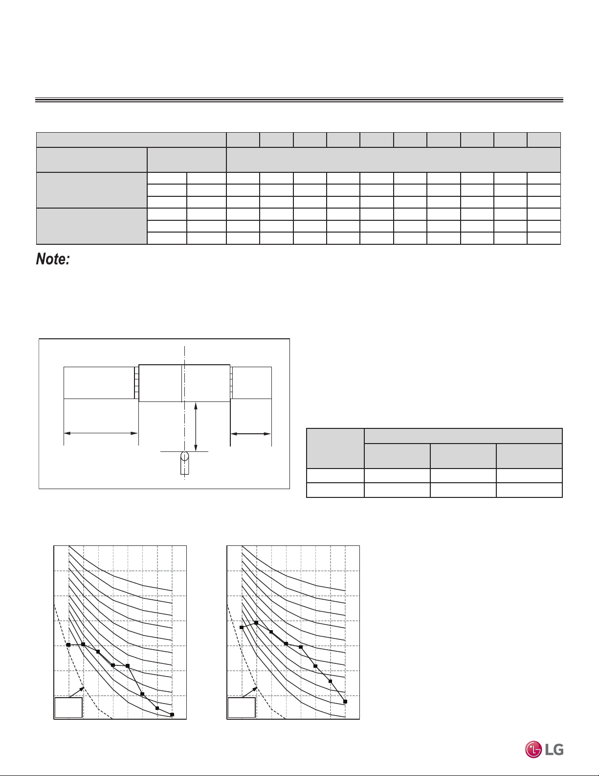
MULTI
F
MAX
MULTI
F
DUCT (HIGH STATIC) INDOOR UNITS
4.9 ft.
6.6 ft.
3.3 ft.
DUCT
DISCHARGE SUCTION
DUCT
Octave Band Sound Pressure Level (0dB = 20μPa)
10
20
30
40
50
60
70
80
Approximate
Hearing
Threshold
Octave Band Center Frequency (Hz)
Octave Band Sound Pressure Level (0dB = 20μPa)
10
20
30
40
50
60
70
80
63 125 250 500 1000 2000 4000 8000
Octave Band Center Frequency (Hz)
63 125 250 500 1000 2000 4000 8000
NC-15
NC-20
NC-25
NC-30
NC-35
NC-40
NC-45
NC-50
NC-55
NC-60
NC-65
NC-15
NC-20
NC-25
NC-30
NC-35
NC-40
NC-45
NC-50
NC-55
NC-60
NC-65
Approximate
Hearing
Threshold
LMHN240HV LMHN360HV
External Static Pressure / Acoustic Data
Table 52:Multi F Ceiling-Concealed Duct (High Static) External Static Pressure Setting Values Table.
Static Pressure (in. wg) 0.1 0.16 0.23 0.31 0.39 0.47 0.55 0.62 0.70 0.78
Model No. / Nominal Capacity
of Indoor Unit (Btu/h)
LMHN240HV
24,000
LMHN360HV
36,000
• To get the desired air flow and external static pressure combination, use the setting value from the table. Using a setting value other
than that listed in the table will not provide the desired combination.
• Table data is based at 230V. Air flow rate varies according to voltage fluctuation.
Airflow Rate / CFM Setting Value (in. wg)
High 688 82 92 103 113 122 131 140 147 154 160
Mid 618 78 89 99 110 119 128 137 144 151 157
Low 530 73 86 96 107 116 125 134 141 148 154
High 1,130 - 124 133 140 148 154 160 - - -
Mid 953 - 112 122 130 137 145 152 - - -
Low 706 - 97 107 117 125 133 141 - - -
Figure 129: Sound Pressure Level Measurement Location.
• Measurements taken with no attenuation and units operating at full
load normal operating condition.
• Sound level will vary depending on a range of factors such as
construction (acoustic absorption coefficient) of particular area in
which the equipment is installed.
• Sound power levels are measured in dB(A)±3.
• Tested in anechoic chamber per ISO Standard 3745.
Table 53:Sound Pressure Levels (dB[A]).
Model No.
LMHN240HV 37 36 35
LMHN360HV 44 42 40
Figure 130: Sound Pressure Level Diagrams.
Multi F and Multi F MAX Indoor Unit Engineering Manual
Sound Pressure Levels (dB[A]) (Cooling and Heating)
High Fan Speed
Medium Fan
Speed
Low Fan Speed
100 | DUCT (HIGH STATIC)
Due to our policy of continuous product innovation, some specications may change without notication.
©LG Electronics U.S.A., Inc., Englewood Cliffs, NJ. All rights reserved. “LG” is a registered trademark of LG Corp.
 Loading...