

Page 1

Please read this manual carefully before operating your set and retain it for future reference.
E-View
Multi Air Conditioner
A4UW30GFH0 [LMU300HHV] / A3UW24GFH0 [LMU240HHV]
A2UW18GFH0 [LMU180HHV]
P/NO : MFL67452453
SERVICE MANUAL
AIR
CONDITIONER
CONFIDENTIAL
Any reproduction, duplication, distribution (including by way of email, facsimile or other electronic means), publication,
modification, copying or transmission of this Service Manual is STRICTLY PROHIBITED unless you have obtained the prior
written consent of the LG Electronics entity from which you received this Service Manual. The material covered by this
prohibition includes, without limitation, any text, graphics or logos in this Service Manual.
Copyright © 2017 LG Electronics Inc. All rights reserved. Only training and service purposes.
Page 2
- 2 -
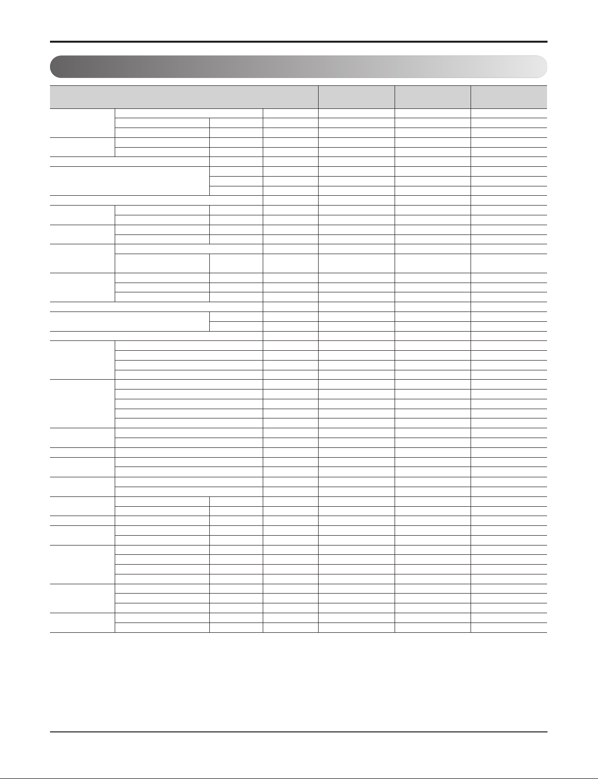
1. Specification
Note:
1. All data are based on the following conditions:
- Cooling Temperature : Indoor 26.7°C(80°F) DB / 19.4°C(66.9°F) WB
Outdoor 35°C(95°F) DB / 23.9°C(75°F) WB
- Heating Temperature : Indoor 21.1°C(70°F) DB / 15.6°C(60.1°F) WB
Outdoor 8.3°C(46.9°F) DB / 6.1°C(43°F) WB
- Piping Length : Interconnected Pipe Length = 5 m (16.4 ft)
- Difference Limit of Elevation (Outdoor ~ Indoor Unit) is Zero.
2.
Wiring cable size must comply with the applicable local and national code.
3. Due to our policy of innovation some specifications may be changed without
notification.
4. Sound Level Values are measured at Anechoic chamber.
Therefore, these values can be increased(maximum 3dB(A)) owing to ambient conditions during opration.
** : The unit could be operated on the followig temperature range only when Low
Ambient Kit installed.
- Cooling : Outdoor Temperature -20°C(-4°F) ~ -10°C(14°F) DB
Model Name
A2UW18GFH0
[LMU180HHV]
A3UW24GFH0
[LMU240HHV]
A4UW30GFH0
[LMU300HHV]
Capacity
Nominal Btu/h Class
18,000 24,000 30,000
Cooling Min~Rated~Max Btu/h
8400~18000~19980 8400~24000~30000 8400~28400~34080
Heating Min~Rated~Max Btu/h
10248~22000~24000 10248~26000~31200 10248~28600~41600
Power Input
Cooling Min~Rated~Max kW
0.87~1.33~1.92 0.93~1.78~2.63 0.94~2.27~3.47
Heating Min~Rated~Max kW
1.24~2.20~3.29 1.25~2.12~3.47 1.29~2.32~3.55
EER/COP Non Ducted -
13.5/2.9 13.5/3.6 12.5/3.6
SEER/HSPF
Non Ducted -
21.0/10.0 21.0/10.7 20.0 / 11.0
Mixed -
19.25/9.5 19.0/9.85 18.75/10.25
Ducted -
17.5/9.0 17.0/9.0 17.5/9.5
Power Supply V, Ø, Hz
208/230, 1, 60 208/230, 1, 60 208/230, 1, 60
Running Current
Cooling Min~Rated~Max A
4.1~6.1~8.7 4.2~7.8~11.9 4.0~10.2~16.7
Heating Min~Rated~Max A
5.6~9.8~14.9 4.8~9.9~14.9 4.2~10.9~15.9
Starting Current
Cooling Max A
- - -
Heating Max A
- - -
Wiring Connections
Power Supply Cable (Included Earth) No. x AWG
3C x 12 3C x 12 3C x 12
Power and Communication Cable
(Included Earth)
Outdoor ~ BD Unit No. x AWG
- - -
Combination
Sum of Indoor Units Capacity Max kBth/h
24 33 40
Number of Indoor Units Max EA
2 3 4
Number of BD Units Max EA
- - -
Casing Color -
Warm Gray Warm Gray Warm Gray
Dimensions
W x H x D mm
950 x 834 x 330 950 x 834 x 330 950 x 834 x 330
W x H x D inch
37-13/32 x 32-27/32 x 13 37-13/32 x 32-27/32 x 13 37-13/32 x 32-27/32 x 13
New Weight kg(lbs)
67 (147.7) 69 (152.1) 69 (152.1)
Compressor
Type -
Twin Rotary Twin Rotary Twin Rotary
Model Model x No.
GJT325M X 1 GJT325M X 1 GJT325M X 1
Motor Type -
BLDC BLDC BLDC
Motor Output W x No.
- - -
Refrigerant
Type -
R410A R410A R410A
Precharged Amount g (oz)
2,800 (98.8) 3,200 (112.8) 3,200 (112.8)
Chargeless-Pipe Length m (ft)
15 (49.2) 22.5 (73.8) 30 (98.4)
Additional Charging Volume g/m (oz/ft)
20 (0.22) 20 (0.22) 20 (0.22)
contorl -
Electronic Expansion Valve Electronic Expansion Valve Electronic Expansion Valve
Refrigerant Oil
Type -
FVC68D FVC68D FVC68D
Charged volume cc x No.
950 x 1 950 x 1 950 x 1
Heat Exchanger (Row x Column x Fins per inch) x No. -
(3 x 38 x 16) x 1 (3 x 38 x 16) x 1 (3 x 38 x 16) x 1
Fan
Type -
Propeller Propeller Propeller
Air Flow Rate m3/min(ft3/min) x No.
65 (2,295) 65 (2,295) 65 (2,295)
Fan Motor
Type -
BLDC BLDC BLDC
Output W x No.
124.2 x 1 124.2 x 1 124.2 x 1
Sound Pressure Level
Cooling Rated dB(A)
50 52 52
Heating Rated dB(A)
54 55 55
Sound Power Level Cooling Rated dB(A)
- - -
Piping Connections
Liquid Outer Dia. mm(inch)
Ø6.35 (1/4) Ø6.35 (1/4) Ø6.35 (1/4)
Gas Outer Dia. mm(inch)
Ø9.52 (3/8) Ø9.52 (3/8) Ø9.52 (3/8)
Piping Length
Total Piping Max. m (ft)
50 (164) 75 (246.1) 75 (246.1)
Main Piping Max. m (ft)
- - -
Total Branch Piping Max. m (ft)
- - -
Each Branch Piping Max. m (ft)
25 (82.0) 25 (82.0) 25 (82.0)
Maximum Height
Difference
Outdoor Unit ~ Indoor Unit Max. m (ft)
15 (49.2) 15 (49.2) 15 (49.2)
Indoor Unit ~ Indoor Unit Max. m (ft)
7.5 (24.6) 7.5 (24.6) 7.5 (24.6)
BD Unit ~ Indoor Unit Max. m (ft)
- - -
Operation Range
(Outdoor Temperature)
Cooling Min. ~ Max. ℃ DB(℉ DB)
-20(-4)** ~ 48(118) -20(-4)** ~ 48(118) -20(-4)** ~ 48(118)
Heating Min. ~ Max. ℃ DB(℉ DB)
-25 (-13) ~ 24 (75) -25 (-13) ~ 24 (75) -25 (-13) ~ 24 (75)
Page 3
- 3 -
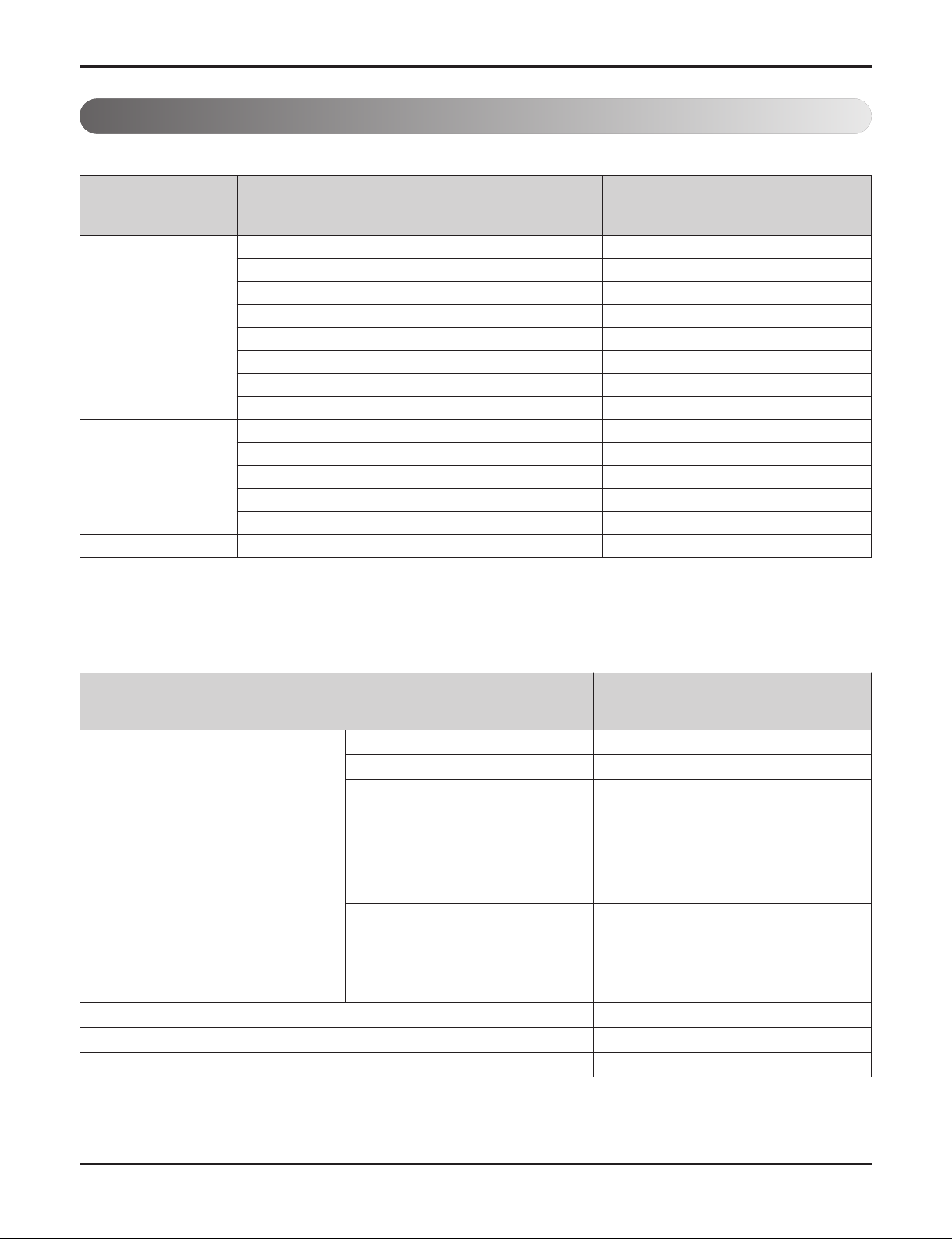
2. List of Functions & Accessory
Note :
O : Applied, × : Not applied
2.2 List of Accessory
2.1 List of Functions
Note :
O : Applied, × : Not applied
Accessory model name : Installed at field, ordered and purchased separately by the corresponding model name, supplied with separate package.
Category Functions
A4UW30GFH0[LMU300HHV]
A3UW24GFH0[LMU240HHV]
A2UW18GFH0[LMU180HHV]
Reliability
Defrost/Deicing
O
High pressure switch
X
Low pressure switch
X
Phase protection
X
Restart delay (3-minutes)
O
Self diagnosis
O
Soft start
O
Test function
X
Convenience
Night Silent Operation
O
Wiring Error Check
O
Peak Control
O
Mode Lock
O
Forced Cooling Operation (Outdoor Unit)
O
Network function Network soluation(LGAP)
O
Device
A4UW30GFH0[LMU300HHV]
A3UW24GFH0[LMU240HHV]
A2UW18GFH0[LMU180HHV]
Central Controller
AC Ez (Simple Controller) PQCSZ250S0
AC Ez Touch PACEZA000
AC Smart IV PACS4B000
ACP IV PACP4B000
AC Manager IV PACM4B000
PI485 PMNFP14A0/PMNFP14A1
BNU (Building Network Unit)
LONWORKS Gateway PLNWKB000
BACnet Gateway PQNFB17C0
Installation
Y branch X
Header branch X
Air Guide X
PDI (power distribution indicator) PQNUD1S00
ODU Dry Contact X
Low Ambient Kit O (Logical operation)
Page 4
- 4 -
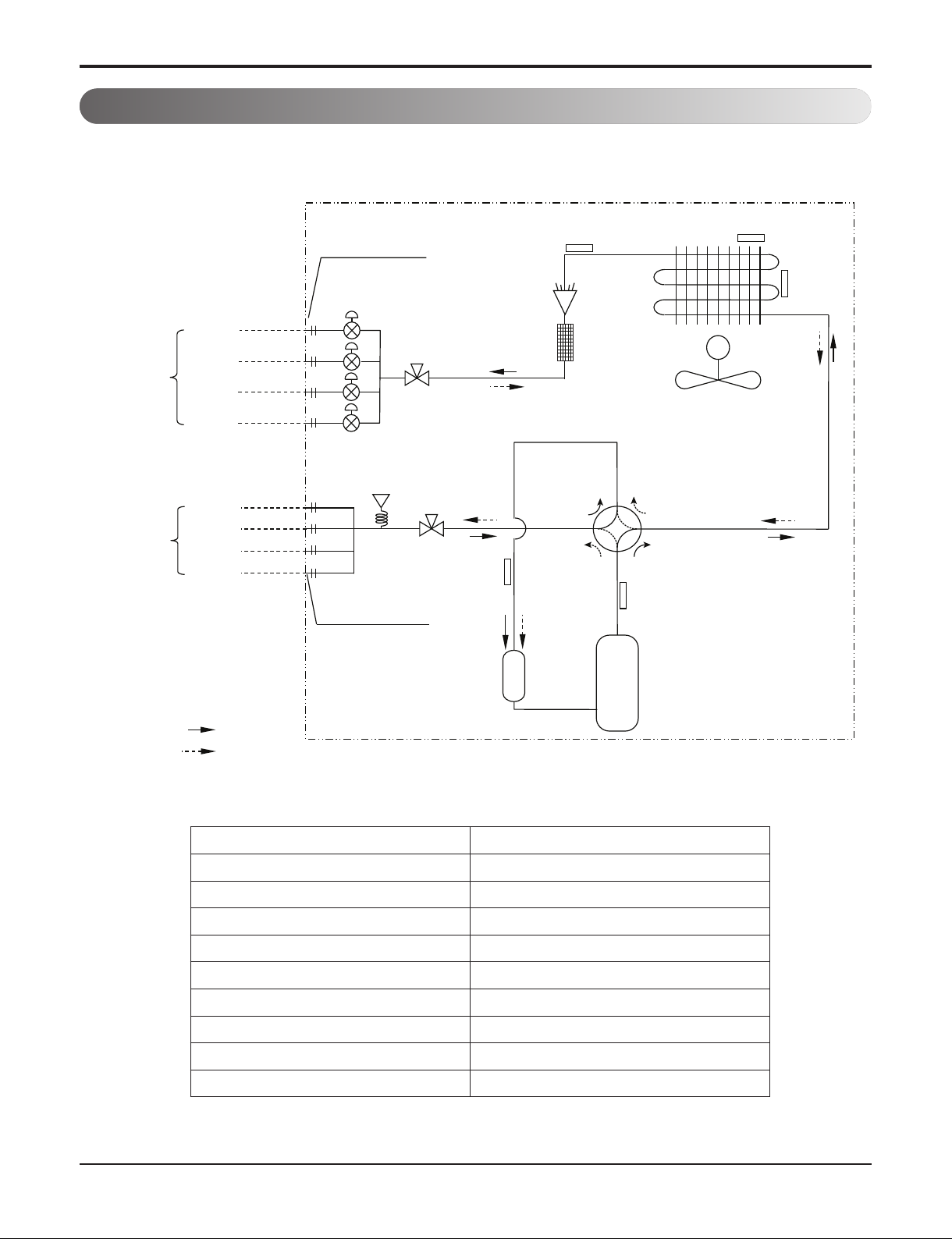
3. Piping Diagrams
PCB Connector Description
CN_MID_BR Cond Middle Pipe
CN_DISCHARGE_BK Discharge Pipe
CN_C_PIPE_VI Cond Out Pipe
CN_SUCTION_GR Suction Pipe
CN_AIR_YL Air
CN_H_PRESS_RD Pressure Sensor
CN_H_GAS_BK Hot Gas Valve
CN_4WAY_YL 4WAY valve
CN_HEATER_BL Base pan heater
3.1 30k
ROOM A
ROOM B
Field Piping
Liquid(Ø6.35)
Field Piping
Gas(Ø9.52)
ROOM C
ROOM D
ROOM A
ROOM B
ROOM C
ROOM D
Outdoor Unit
Ø 6.35
Flare Connection
Electronic
Expansion
Valve
Main SVC V/V
Pressure
Sensor
Ø9.52
Flare Connection
Main SVC V/V
Suction
Temperature
Thermistor
Condenser Out
Temperature
Thermistor
Inlet Air
Temperature
Thermistor
Discharge
Temperature
Thermistor
M
Condensing
Temperature
Thermistor
Accumulator
: Cooling
: Heating
Inverter
Compressor
Page 5
- 5 -
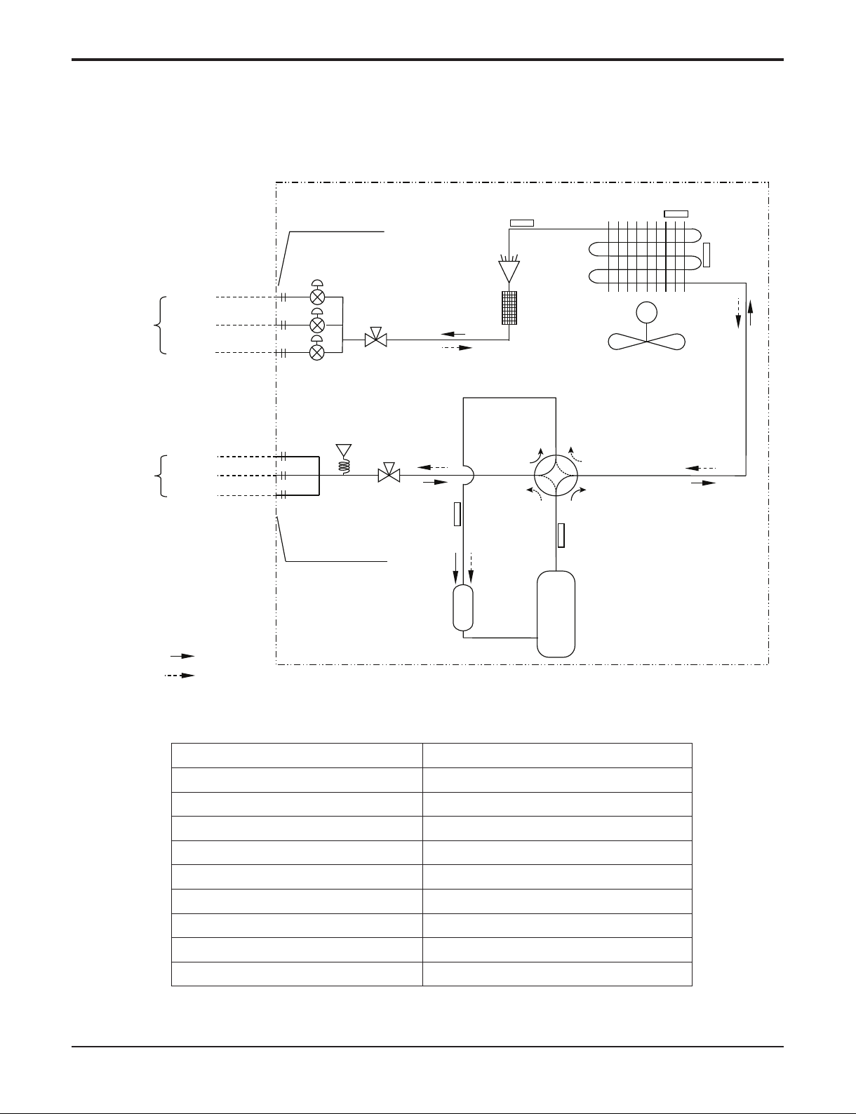
PCB Connector Description
CN_MID_BR Cond Middle Pipe
CN_DISCHARGE_BK Discharge Pipe
CN_C_PIPE_VI Cond Out Pipe
CN_SUCTION_GR Suction Pipe
CN_AIR_YL Air
CN_H_PRESS_RD Pressure Sensor
CN_H_GAS_BK Hot Gas Valve
CN_4WAY_YL 4WAY valve
CN_HEATER_BL Base pan heater
3.2 24k
Field Piping
Liquid(Ø6.35)
Field Piping
Gas(Ø9.52)
ROOM A
ROOM B
ROOM C
ROOM A
ROOM B
ROOM C
Outdoor Unit
Ø 6.35
Flare Connection
Electronic
Expansion
Valve
Main SVC V/V
Pressure
Sensor
Ø9.52
Flare Connection
Main SVC V/V
Suction
Temperature
Thermistor
Condenser Out
Temperature
Thermistor
Inlet Air
Temperature
Thermistor
Discharge
Temperature
Thermistor
M
Condensing
Temperature
Thermistor
Accumulator
: Cooling
: Heating
Inverter
Compressor
Page 6

- 6 -
PCB Connector Description
CN_MID_BR Cond Middle Pipe
CN_DISCHARGE_BK Discharge Pipe
CN_C_PIPE_VI Cond Out Pipe
CN_SUCTION_GR Suction Pipe
CN_AIR_YL Air
CN_H_PRESS_RD Pressure Sensor
CN_H_GAS_BK Hot Gas Valve
CN_4WAY_YL 4WAY valve
CN_HEATER_BL Base pan heater
3.3 18k
Field Piping
Liquid(Ø6.35)
Field Piping
Gas(Ø9.52)
ROOM A
ROOM B
ROOM A
ROOM B
Outdoor Unit
Ø 6.35
Flare Connection
Electronic
Expansion
Valve
Main SVC V/V
Pressure
Sensor
Ø9.52
Flare Connection
Main SVC V/V
Suction
Temperature
Thermistor
Condenser Out
Temperature
Thermistor
Inlet Air
Temperature
Thermistor
Discharge
Temperature
Thermistor
M
Condensing
Temperature
Thermistor
Accumulator
: Cooling
: Heating
Inverter
Compressor
Page 7

- 7 -
4. Wiring Diagrams
4.1 30k
Page 8

- 8 -
4.2 24k
Page 9

- 9 -
4.3 18k
Page 10

- 10 -
INV PCB
CN-UVW
CN-C_PIPE CN-SUCTION
CN-AIR
CN-LGMV
CN-MID
CN-BLDC
SW1
CN-DISCHARGE
CN-H_PRESS
CN-EEV4
CN-EEV3
CN-EEV2
CN-POWER
CN-EEV1
REACTOR_OUT2
REACTOR_IN
REACTOR_OUT1
CN-HEATER2
CN-H_GAS
CN-4WAY
Page 11

- 11 -
5. Exploded View
Location No. Description Sensor Information Housing Color
263230A Thermistor(CN_DISCHA_BK) Discharge Pipe Black
263230B Thermistor(CN_SUCTION_GR) Suction Pipe Green
263230C Thermistor(CN_C_PIPE_VI) Cond Out Pipe Violet
263230D Thermistor(CN_MID_BR) Cond Middle Pipe Brown
263230E Thermistor(CN_AIR_YL) Air Yellow
165000 CN_H_PRESS_RD Pressure Sensor Red
5.1 30k
137213C
447910
435512
554031
435300
437212
559010
437211
349480
546810
549610
237202
430410
137213A
152503
552202
268711A
W6631
552116
561410
W6200
554160
550140
268711B
165000
661400A
661400B
661400C
661400D
W49810
263230A
552203A
552203B
552200B
552115
137213B
W4986A
552113
W4986B
435301
263230D
263230E
W6640A
W6640B
263230B
649950
263230C
Page 12

- 12 -
Location No. Description Sensor Information Housing Color
263230A Thermistor(CN_DISCHA_BK) Discharge Pipe Black
263230B Thermistor(CN_SUCTION_GR) Suction Pipe Green
263230C Thermistor(CN_C_PIPE_VI) Cond Out Pipe Violet
263230D Thermistor(CN_MID_BR) Cond Middle Pipe Brown
263230E Thermistor(CN_AIR_YL) Air Yellow
165000 CN_H_PRESS_RD Pressure Sensor Red
5.2 24k
137213C
447910
435512
554031
435300
437212
559010
437211
349480
546810
549610
237202
430410
137213A
152503
552202
268711A
W6631
552116
561410
W6200
554160
550140
268711B
165000
661400A
661400B
661400C
W49810
263230A
552203A
552203B
552200B
552115
137213B
W4986A
552113
W4986B
435301
263230D
263230E
W6640A
W6640B
263230B
649950
263230C
Page 13

- 13 -
Location No. Description Sensor Information Housing Color
263230A Thermistor(CN_DISCHA_BK) Discharge Pipe Black
263230B Thermistor(CN_SUCTION_GR) Suction Pipe Green
263230C Thermistor(CN_C_PIPE_VI) Cond Out Pipe Violet
263230D Thermistor(CN_MID_BR) Cond Middle Pipe Brown
263230E Thermistor(CN_AIR_YL) Air Yellow
165000 CN_H_PRESS_RD Pressure Sensor Red
5.3 18k
137213C
447910
435512
554031
435300
437212
559010
437211
349480
546810
549610
237202
430410
137213A
152503
552202
268711A
W6631
552116
561410
W6200
554160
550140
268711B
165000
661400A
661400B
W49810
263230A
552203A
552203B
552200B
552115
137213B
W4986A
552113
W4986B
435301
263230D
263230E
W6640A
W6640B
263230B
649950
263230C
Page 14

 Loading...