

LG LFX25973 Series, LFX28979 SERIES Service Manual
REFRIGERATOR
SERVICE MANUAL
CAUTION
BEFORE SERVICING THE UNIT,
READ THE SAFETY PRECAUTIONS IN THIS MANUAL.
MODEL : LFX25973**
COLOR : STAINLESS(ST)
WESTERN BLACK
SUPER WHITE

CONTENTS
1. SPECIFICATIONS ............................................................................................................................................ 3
2. PARTS IDENTIFICATION ................................................................................................................................ 4
3. DISASSEMBLY ........................................................................................................................................... 5-16
REMOVING AND REPLACING REFRIGERATOR DOORS ............................................................................ 5
DOOR ............................................................................................................................................................... 6
DOOR ALIGNMENT ........................................................................................................................................ 7
FAN AND FAN MOTOR(EVAPORATOR) ....................................................................................................... 7
DEFROST CONTROL ASSEMBLY ................................................................................................................. 7
LAMP ............................................................................................................................................................... 8
MULTI DUCT ................................................................................................................................................... 8
MAIN PWB........................................................................................................................................................ 8
DISPENSER .................................................................................................................................................... 9
DISPLAY PCB ................................................................................................................................................. 9
ICE BUTTON ASSEMBLY ............................................................................................................................... 9
WATER BUTTON ASSMEBLY ........................................................................................................................ 9
ICE COMPARTMENT DOOR REPLACEMENT .............................................................................................. 9
ICEMAKER REPLACEMENT ........................................................................................................................ 10
SUB PWB FOR WORKING DISPENSER ..................................................................................................... 10
CAP DUCT MOTOR REPLACEMENT ........................................................................................................... 11
HOW TO REMOVE THE ICE BIN ................................................................................................................. 12
HOW TO INSERT THE ICE BIN .................................................................................................................... 12
HOW TO REMOVE AND REINSTALL THE PULLOUT DRAWER .......................................................... 13-14
WATER VALVE DISASSEMBLY METHOD .................................................................................................. 15
FAN AND FAN MOTOR DISASSEMBLY METHOD ...................................................................................... 15
FREEZER DRAWER ..................................................................................................................................... 16
4. ADJUSTMENT ............................................................................................................................................... 17
COMPRESSOR ............................................................................................................................................. 17
5. CIRCUIT DIAGRAM ....................................................................................................................................... 18
6. TROUBLESHOOTING ...............................................................................................................................19-20
ERROR CODE SUMMARY .......................................................................................................................19-20
7. PCB PICTURE .......................................................................................................................................... 21-22
MAIN PCB ...................................................................................................................................................... 21
DISPLAY PCB & SUB PCB .......................................................................................................................... 22
8. TROUBLESHOOTING WITH ERROR DISPLAY ..................................................................................... 23-31
9. TROUBLESHOOTING WITHOUT ERROR DISPLAY .............................................................................. 32-40
10. REFERENCE .......................................................................................................................................... 41-44
11. COMPONENT TESTING INFORMATION .............................................................................................. 45-53
12. COMPRESSOR TROUBLESHOOTING.................................................................................................. 54-65
13. OPERATION PRINCIPLE AND REPAIR METHOD OF ICEMAKER (ICE ROOM) ................................ 66-69
14. OPERATION PRINCIPLE AND REPAIR METHOD OF ICEMAKER (FREEZER ROOM) ..................... 70-73
15. DESCRIPTION OF FUNCTION & CIRCUIT OF MICOM ....................................................................... 74-77
FUNCTION ............................................................................................................................................. 74-77
16. EXPLODED VIEW ...................................................................................................................................... 1-7
SAFETY PRECAUTIONS
Please read the following instructions before servicing your
refrigerator.
1. Unplug the power before handling any elctrical
componets.
2. Check the rated current, voltage, and capacity.
3. Take caution not to get water near any electrical
components.
4. Use exact replacement parts.
5. Remove any objects from the top prior to tilting the
product.
- 2 -
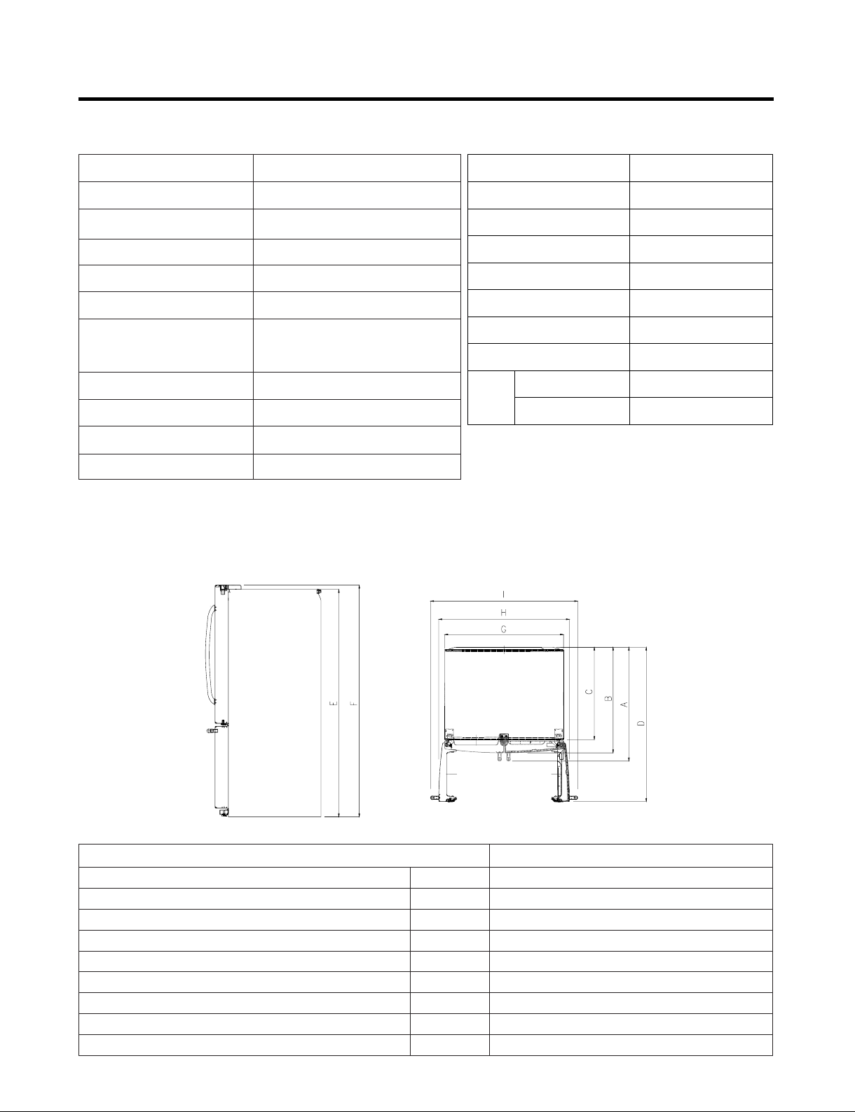
1. SPECIFICATIONS
25 cu. ft
ITEMS SPECIFICATIONS
DOOR DESIGN
DIMENSIONS (inches)
NET WEIGHT (pounds)
COOLING SYSTEM
TEMPERATURE CONTROL
DEFROSTING SYSTEM
DOOR FINISH
HANDLE TYPE
INNER CASE
INSULATION
DIMENSIONS
Side Rounded
35 3/4X 34 1/4X 69 3/4(WXDXH) 25cu.ft
308.65 (25cu.ft)
Fan Cooling
Micom Control
Full Automatic
Heater Defrost
PCM, Stainless
Bar
ABS Resin
Polyurethane Foam
ITEMS SPECIFICATIONS
VEGETABLE TRAY
COMPRESSOR
EVAPORATOR
CONDENSER
REFRIGERANT
LUBRICATING OIL
DEFROSTING DEVICE
REFRIGERATOR
LAMP
FREEZER
Opaque Drawer Type
Linear
Fin Tube Type
Spiral Condenser
R-134a (145g)
FREOLα8G (180 ml)
SHEATH HEATER
LED Module(21)
Bulb Lamp
Description LMX25973**
Depth w/ Handles
Depth w/o Handles
Depth w/o Door
Depth (Total with Door Open)
Height to Top of Case
Height to Top of Door Hinge
Width
Width (door open 90 deg. w/o handle)
Width (door open 90 deg. w/ handle)
- 3 -
A
B
C
D
E
F
G
H
I
34 1/4 in.
31 3/4 in.
27 7/8 in.
46 1/2 in.
68 3/8 in.
69 3/4 in.
35 3/4 in.
39 1/4 in.
44 1/4 in.
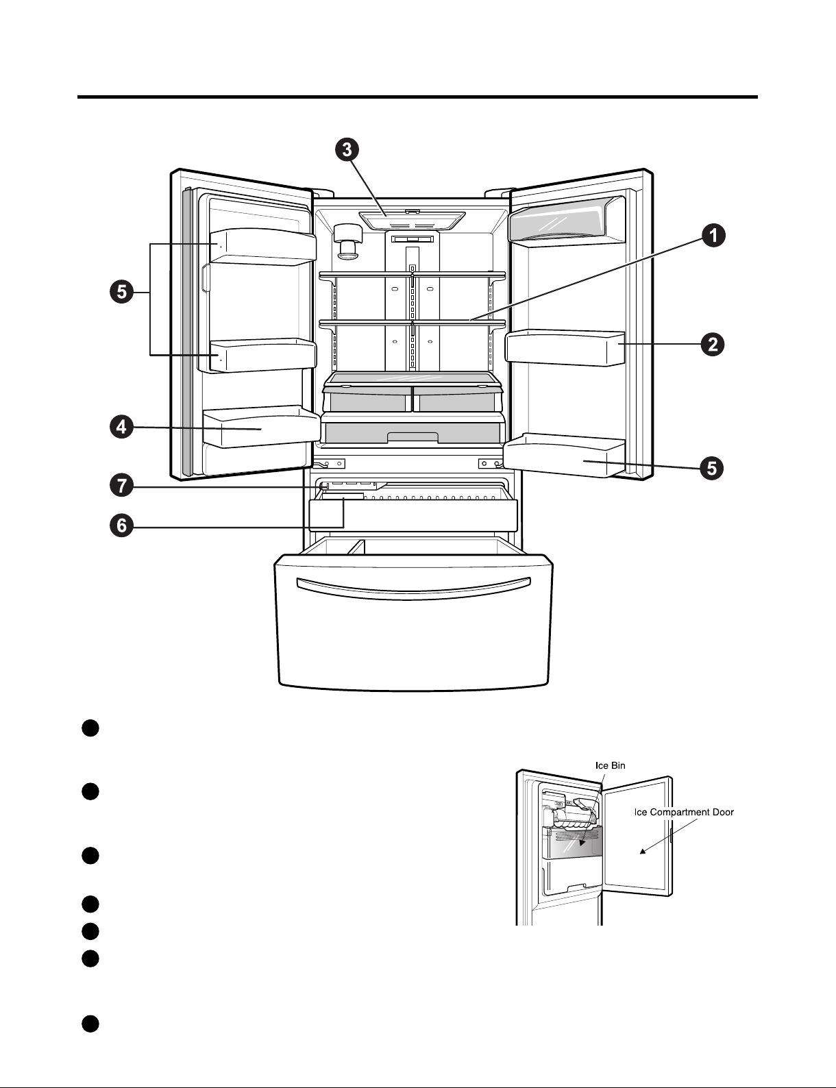
2. PARTS IDENTIFICATION
ADJUSTABLE REFRIGERATOR SHELVING
1
The refrigerator compartment shelves are adjustable to allow
flexibility for storage needs.
GALLON STORAGE BINS
2
Two interchangeable bins can be arranged to suit your
storage needs.
LED INTERIOR LAMPS
3
Refrigerator interior is lit by the LED array.
CAN STORAGE BIN
4
FIXED DOOR BINS
5
REMOVABLE ICE STORAGE BIN
6
The ice storage bin can be removed to fill ice buckets,
coolers, or pitchers
Auto Icemaker
7
- 4 -
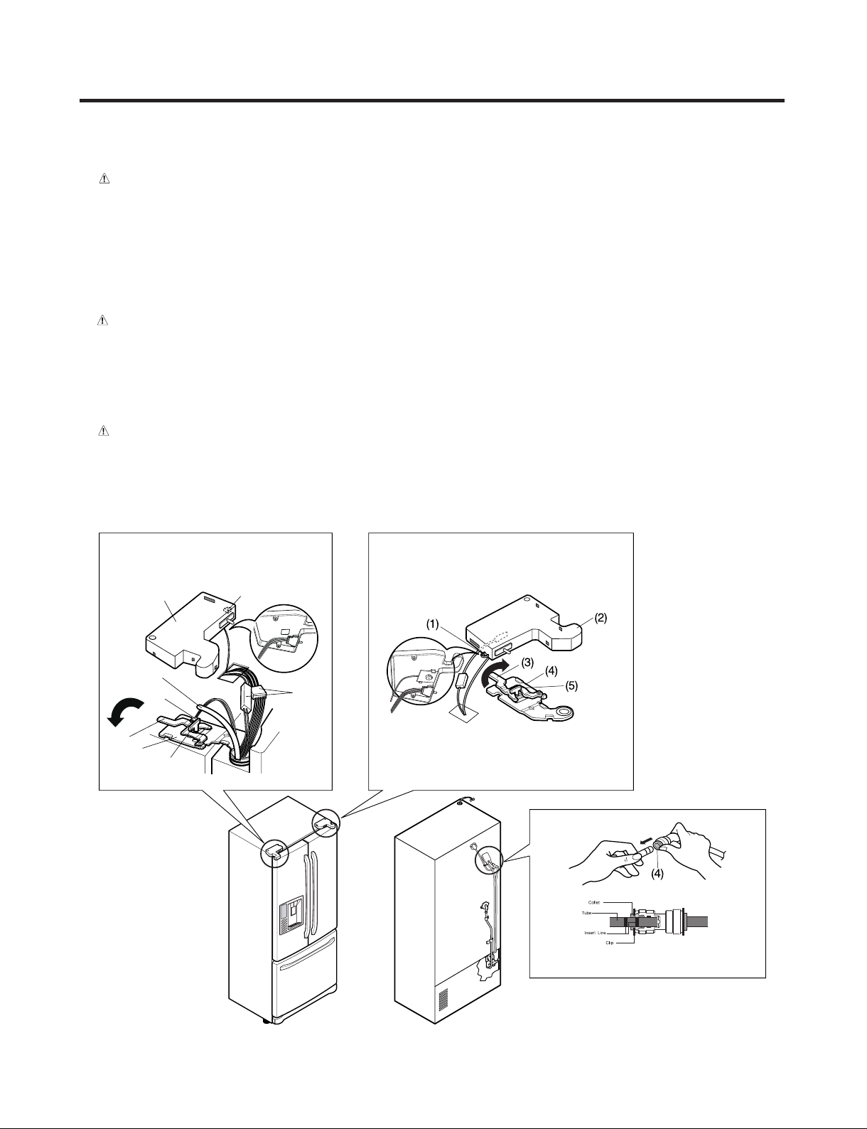
3. DISASSEMBLY
(1)
(2)
(4)
(3)
(6)
(7)
(8)
(5)
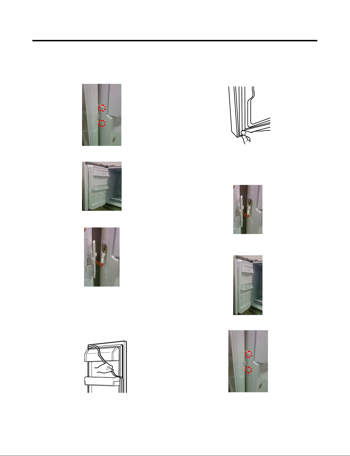
3-1 REMOVING AND REPLACING REFRIGERATOR DOORS
●
Removing Refrigerator Door
CAUTION : Before you begin, unplug the refrigerator. Remove food and bins from doors.
▶
Left Door -FIG. 2
1. Disconnect water supply tube by pushing back on the disconnect ring (4).-FIG. 1
2. Open door. Loosen top hinge cover screw (1).
Use flat tip screwdriver to pry back hooks on front underside of cover (2). Lift up cover.
3. Disconnect door switch wire harness. Remove cover.
4. Pull out the tube(3).
5. Disconnect the two wire harnesses (4). Remove the grounding screw (5).
6. Rotate hinge lever (6) counterclockwise. Lift top hinge (7) free of hinge lever latch (8).
CAUTION : When lifting hinge free of latch, be careful that door does not fall forward.
7. Place door, inside facing up, down onto a non-scratching surface.
▶
Right Door -FIG. 3
1. Open door. Loosen top hinge cover screw (1). Lift up cover (2).
2. Disconnect door switch wire harness. Remove cover.
3. Rotate hinge lever (3) clockwise. Lift top hinge (4) free of hinge lever latch (5).
4. Lift door from middle hinge pin and remove door.
CAUTION : When lifting hinge free of latch, be careful that door does not fall forward.
5. Place door, inside facing up, down onto a non-scratching surface.
Figure 2 Figure 3
Figure 1
- 5 -
3-2 DOOR
●
Pillar Removal
1. Remove 2 screws.
2. Lift pillar up carefully.
3. Disconnect wire harness.
●
Door Gasket Replacement
1. Insert gasket into channel
Press gasket into channels on the four remaining
sides of door.
●
Pillar Replacement
1. Connect wire harness.
●
Door Gasket Removal
1. Remove gasket
Pull gasket free from gasket channel on the four
remaining sides of door.
2. Insert pillar into channel.
Inserting pillar assy’ into bracket, door
3. Assemble 2 screws.
- 6 -
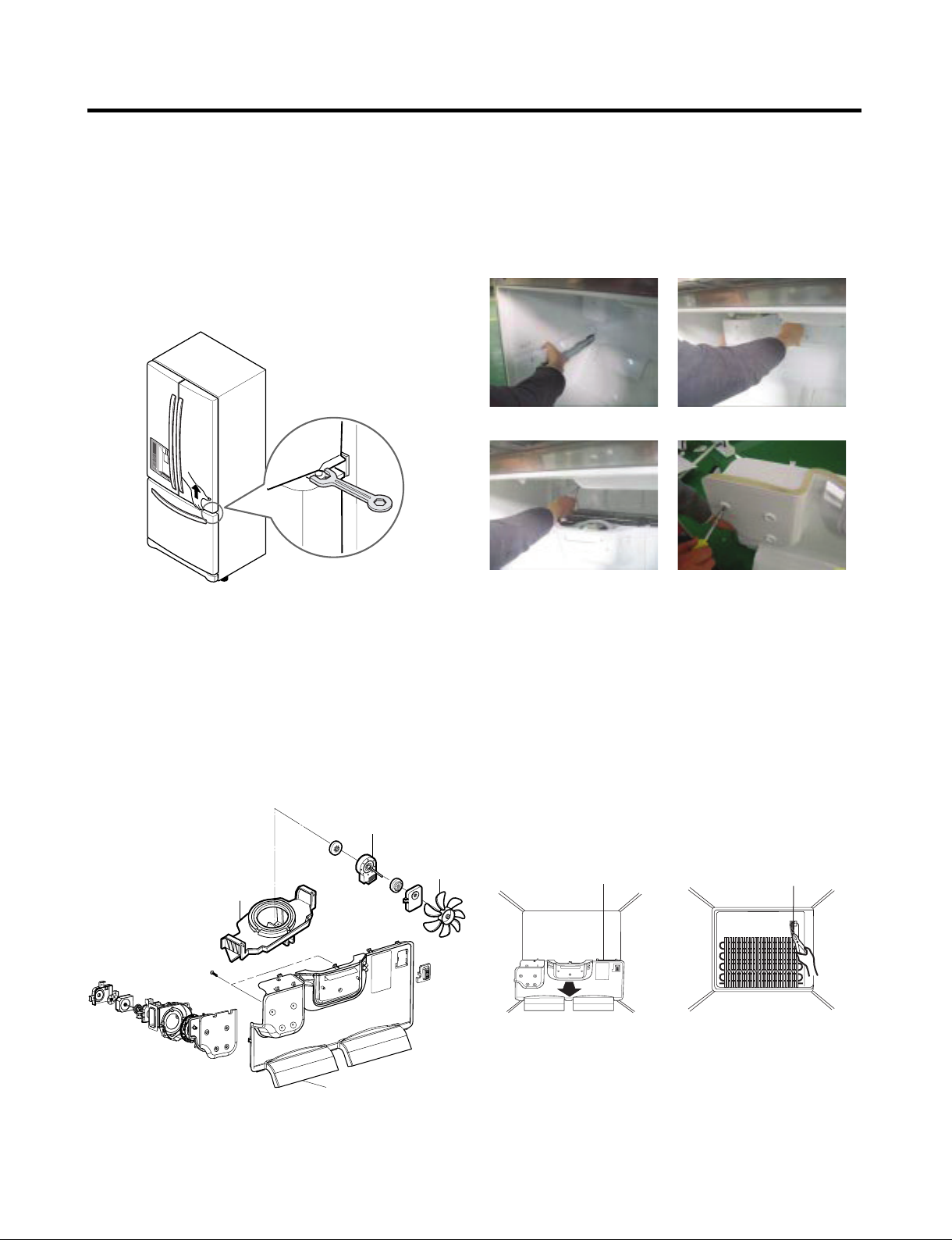
3-3 DOOR ALIGNMENT
If the space between your doors is uneven, follow the
instructions below to align the doors:
Remove the Base Grillie. Turn the leveling legs (CCW) to
raise or (CW) to lower the height of the front of the
refrigerator by using flat blade screw driver or 11/32"
wrench. Use the wrench (Included with the User Manual) to
adjust the bolt in the door hinge to adjust the height. (CCW
to raise or CW to lower the height.)
* Ice Fan Scroll Assembly Replacement
1) Remove the plastic guide for slides on left side by
unscrewing phillips head screws.
2) Pull the grille forward as shown in the second picture.
3) Disconnect wire harness of the grille.
4) Remove the scroll assembly by loosening all screws.
(1) (2)
(3) (4)
3-4 FAN AND FAN MOTOR(EVAPORATOR)
1. Remove the freezer shelf.
2. Remove the plastic guide for slides on left side by
unscrewing phillips head screws.
3. Remove the grille by removing one screw and pulling the
grille forward.
4. Remove the Fan Motor assembly by loosening 2 screws
and disassembling the shroud.
5. Pull out the fan and separate the Fan Motor and Bracket.
FAN MOTOR
BRACKET
MOTOR
Ice fan assembly
FAN
3-5 DEFROST CONTROL ASSEMBLY
Defrost Control assembly consists of Defrost Sensor and
FUSE-M.
The Defrost Sensor works to defrost automatically. It is
attached to the metal side of the Evaporator and senses its
temperature. At 46°F (8°C), it turns the Defrost Heater off.
Fuse-M is a safety device for preventing over-heating of the
Heater when defrosting.
1. Pull out the grille assembly. (Figure 4)
2. Separate the connector with the Defrost Control
assembly and replace the Defrost Control assembly after
cutting the Tie Wrap. (Figure 5)
GRILLE ASSEMBLY
Figure 4 Figure 5
DEFROST-CONTROL
ASSEMBLY
GRILLE
- 7 -
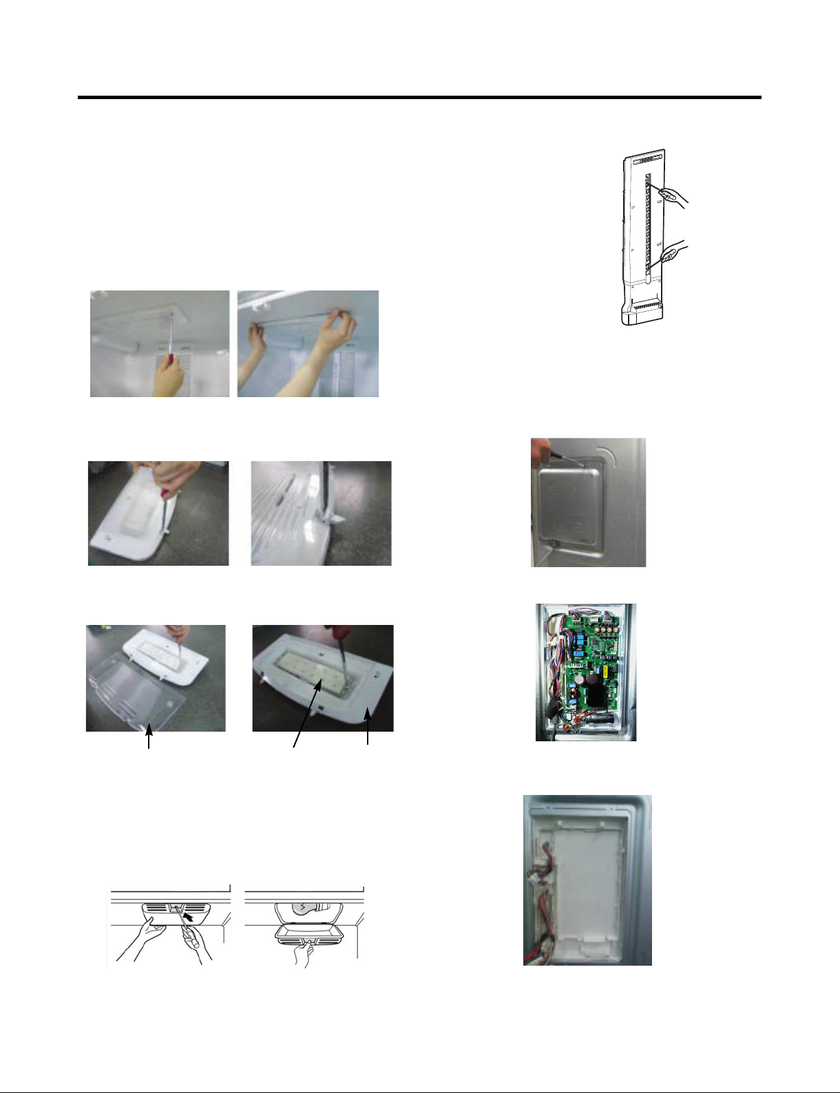
3-6 LAMP
Unplug Refrigerator, or disconnect power at the circuit
breaker.
If necessary, remove top shelf or shelves.
3-6-1 Refrigerator Compartment Lamp
1) Release 2 screws.
2) Hold both ends with your both hands and pull it
downward to remove it.
3) Use a flat tool as shown below to remove the cover
lamp.
3-7 MULTI DUCT
1. Remove the upper and
lower Caps by using a
flat screwdriver, and
remove 2 screws.
(Figure 6)
2. Disconnect the lead wire
on the bottom position.
Figure 6
3-8 MAIN PWB
1) Loosen 3 screws on the PWB cover.
4) As shown below, use a flat tool to remove the cover
lamp.
Cover, Lamp
3-6-2 Freezer Compartment Lamp
1. Unplug refrigerator power cord from outlet.
2. Remove screw with driver.
3. Grasp the cover Lamp, pull the cover downward.
LED, Assembly Case Lamp
2) Remove the PWB cover
3) Disconnect wire harness and replace the main PWB in
the reverse order of removal.
- 8 -
3-9 DISPENSER
1) Pull out the drain 2) Hold the inner side of
cover dispenser with
both hands at the handle
side to pull it out forward.
3) If nozzle is interfered with button,
push and pull out the bottom of
button.
CAUTION: When replacing the dispensor cover in the
reverse order of removal, be careful that the lead wire
does not come out and the water tube is not pinched by
the dispensor.
4) Remove the
connected part
of Lead wire.
3-11 ICE BUTTON ASSEMBLY
1) Remove the screw fixing the button lever.
2) Push the spring from the hanging hook to remove it.
3) Apply some pressure to the rib in
button in
Button Lever
direction.
direction and lift the
3-12 WATER BUTTON ASSMEBLY
1) Remove screws.
2) Grasp the Button assembly and lift up.
Button Lever
3-10 DISPLAY PCB
As shown below, remove 1 case PCB fixing screw.
Remove the display PCB fixing screw.
Case, PCB Display PCB
3-13 ICE COMPARTMENT DOOR REPLACEMENT
1) Loosen the front screw as shown in the picture.
2) Lift up the hinge with one hand.
3) Pull out the Ice Compartment Door with the other hand.
hinge
- 9 -
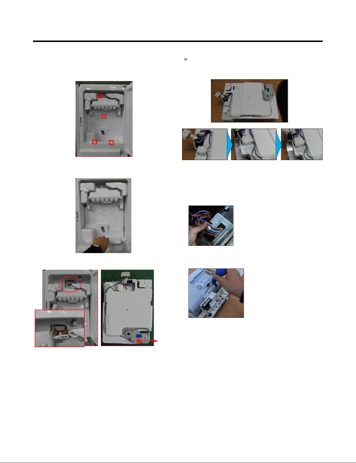
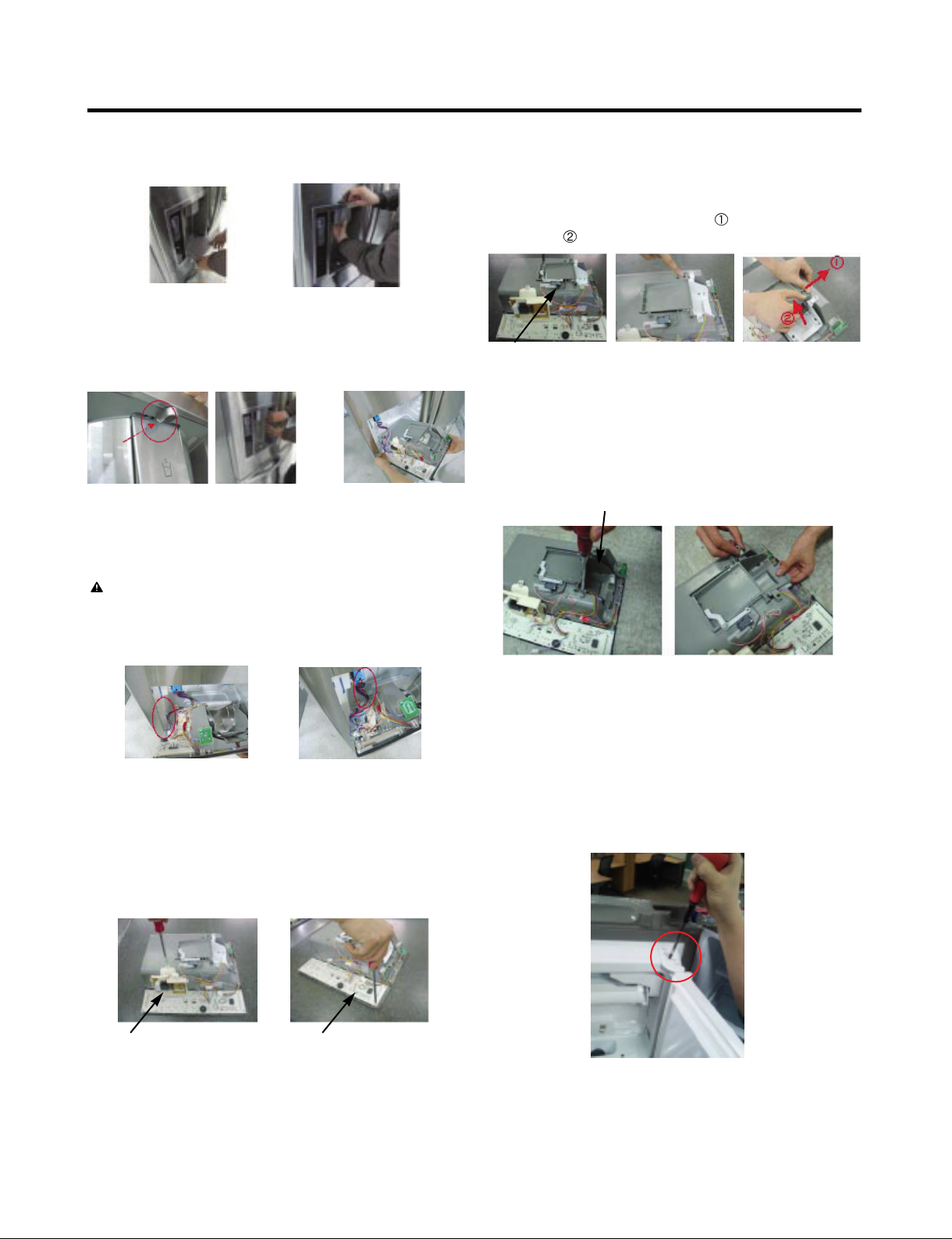
3-14 ICEMAKER REPLACEMENT
1) Remove the stainless screws marked in the picture
below.
2) Grasp the bottom of motor cover assembly and pull it out
slowly.
Caution: Check to see if the housing is stuck to mold and
taped. If the housing is not on its original position, it will
disturb Cover, motor to be positioned to the unit.
3-15 SUB PWB FOR WORKING DISPENSER
1) Disconnect the wire harness.
3) Disconnect wire harness from wall of compartment.
2) Loosen the screw on the sub PWB and replace the sub
PWB in the reverse order of removal.
In-door
motor
- 10 -
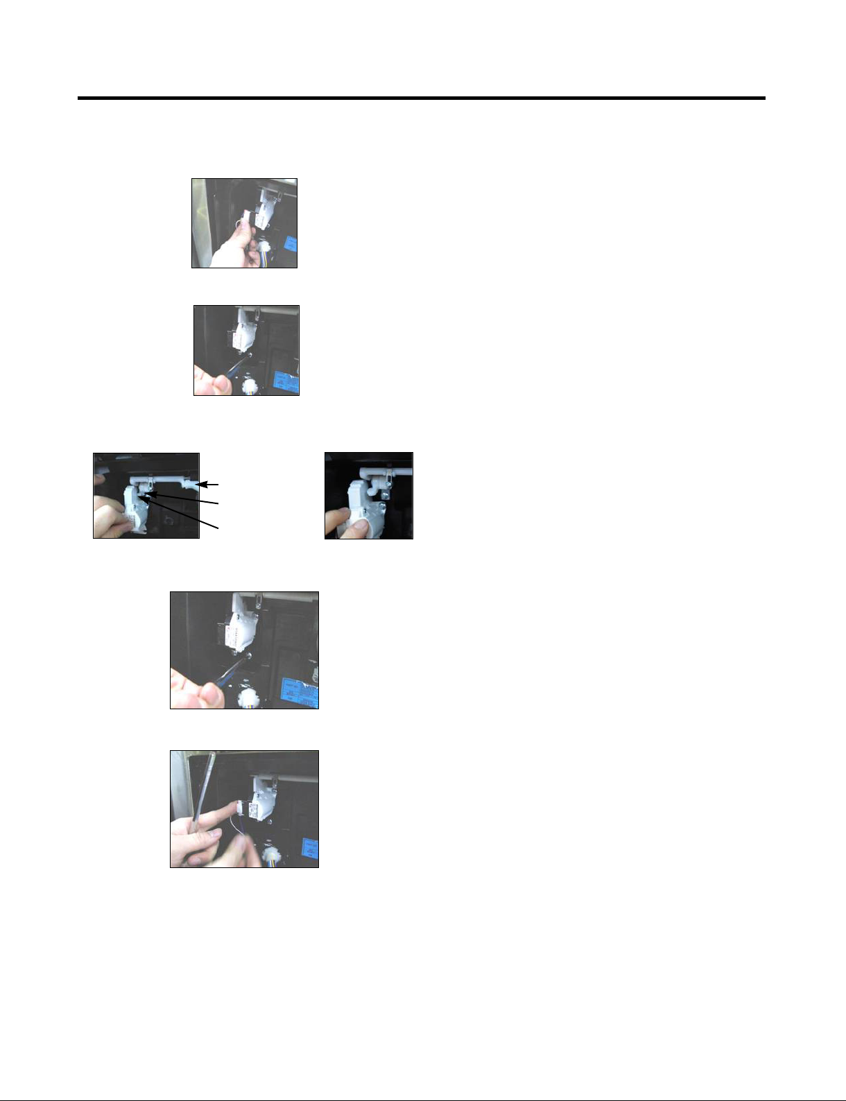
3-16 CAP DUCT MOTOR REPLACEMENT
1) Separate the Housing of the Cap Duct Motor.
2) Unscrew 3 screws to disassemble the motor.
3) When replacing to a new Motor, always check position of
the Duct Door and Link to install the Motor.
Duct Door
Link
Cap Duct Motor
NG Position
4) Assemble on the screws.
5) Connect the Housing.
- 11 -
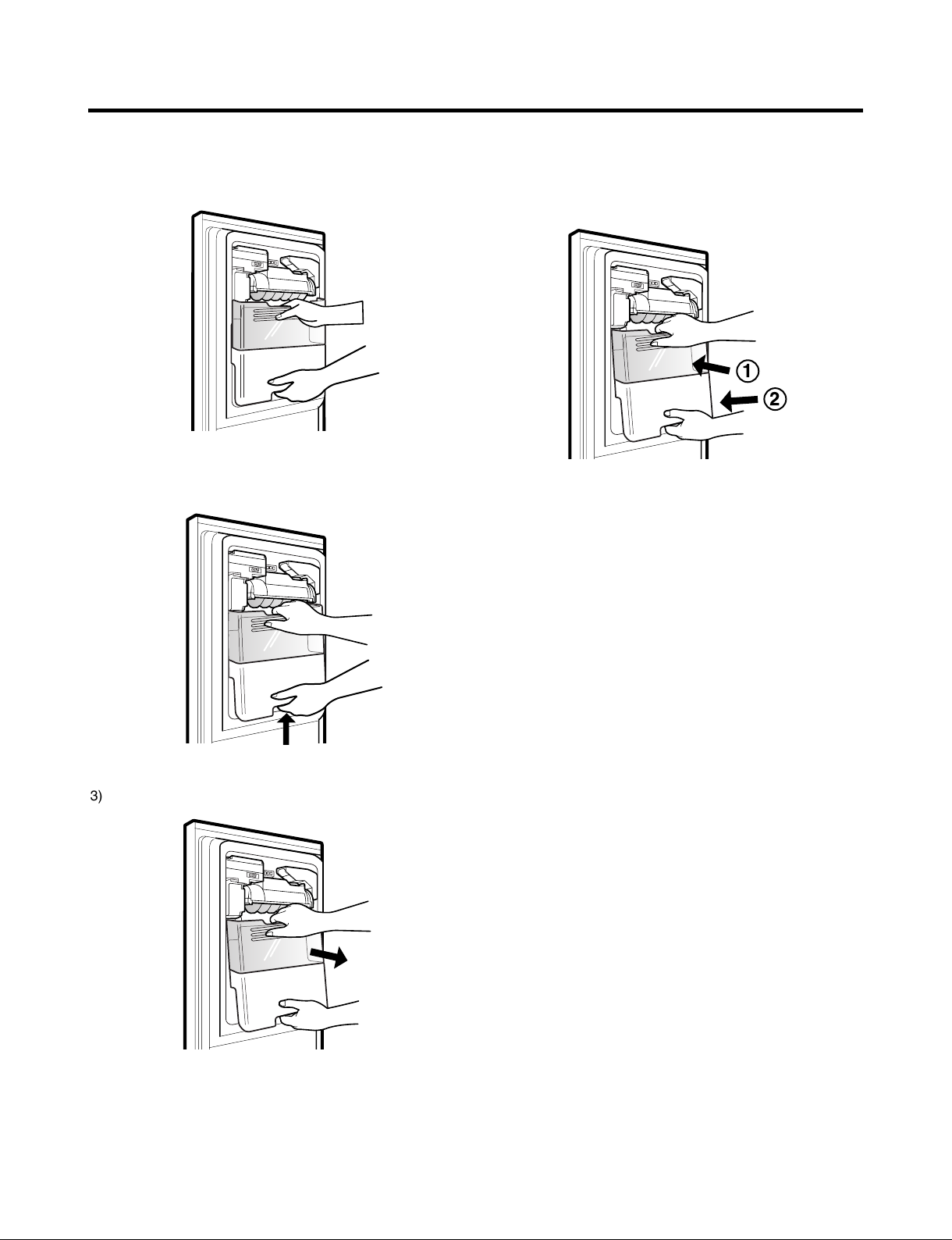
3-17 HOW TO REMOVE THE ICE BIN
1) Grip the handles, as shown in the picture.
2) Lift the lower part slightly.
3-18 HOW TO INSERT THE ICE BIN
1) Insert the Ice Bin, slightly tilting it to avoid touching the
Icemaker. (Especially, Ice-Detecting Sensor)
3) Take the Ice Bin out slowly.
- 12 -
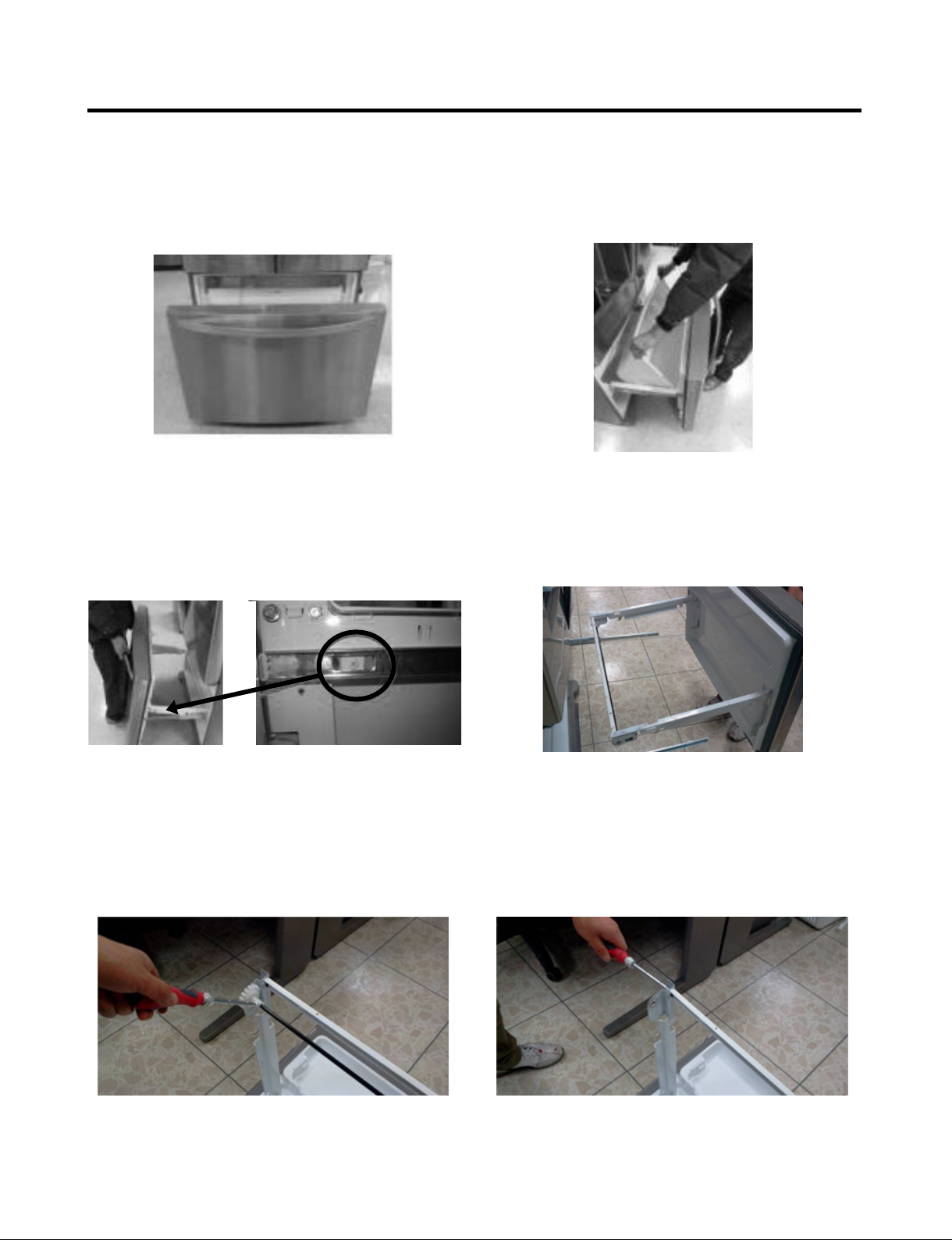
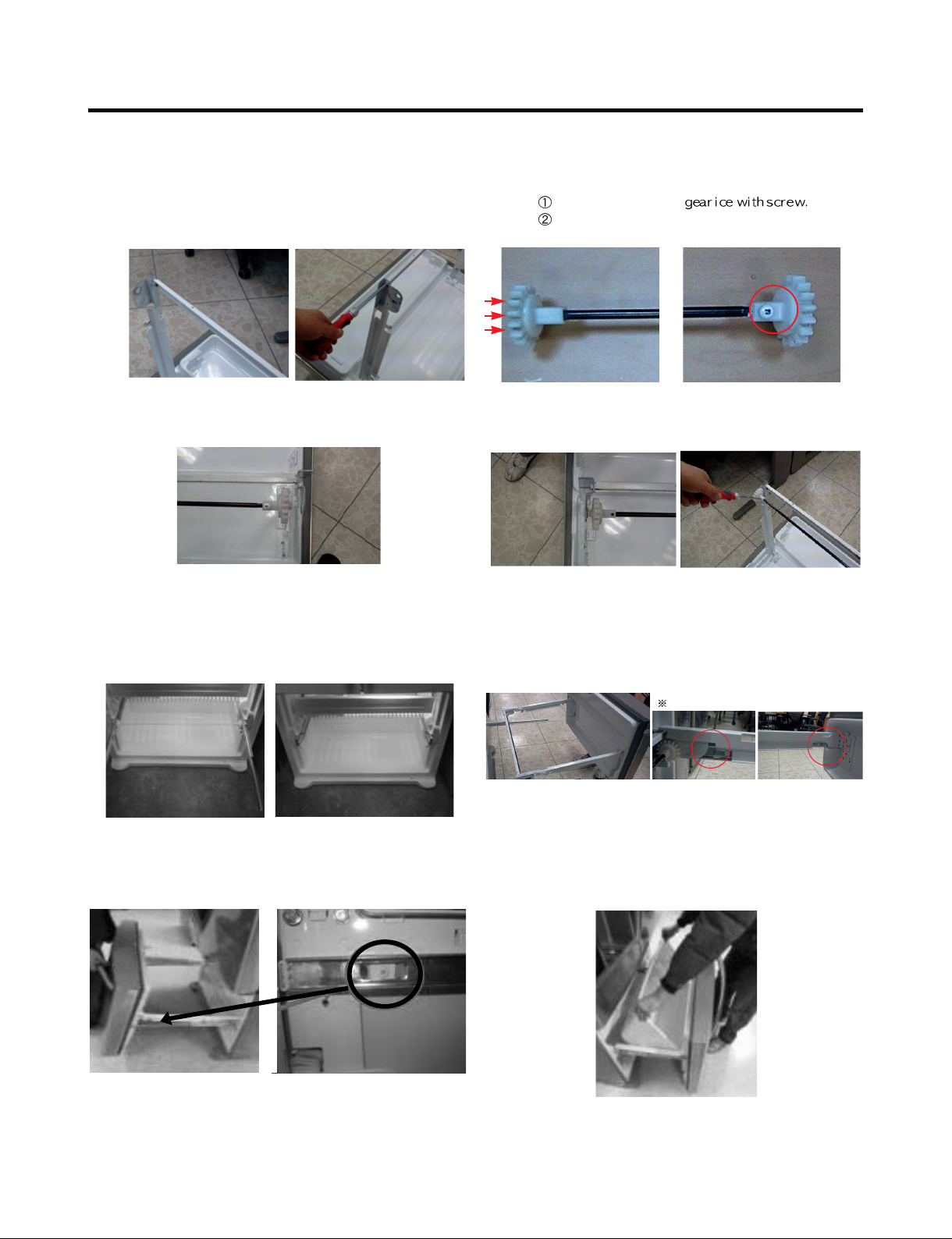
3-19 HOW TO REMOVE AND REINSTALL THE PULLOUT DRAWER
3-19-1 Follow Steps to Remove
Step 1) Open the freezer door.
Step 3) Remove the two screws from the guide rails (one
from each side).
Step 2) Remove the lower basket.
Step 4) Removal of the freezer door is done by lifting
clear of the rail support.Fully extend both rails.
Step 5) Remove only 1 screw of gear ice, and disassemble
the bar and gear ice
Step 6) Remove 2 screws of both side of supporter covers
tv and disassemble the supporter cover tv.
- 13 -
3-19-2 Follow Steps to Reinstall
Step 1) Insert both side of supporter cover tv into connector
rails, and then screw them.
Step 3) Put gear ice assembled with the bar by screw into
connector rail’s hole.
Step 5) The rail system will align itself by pushing the rails
all the way into the freezer section.
Pull the rails back out to full extension.
Step 2) Assemble a bar and
Push the otherside of the gear to inside of the bar.
Step 4) Insert opposite gear ice into connector rail and
screwthem
Step 6) Reinstall the freezer door by inserting the rail tabs
into the guide rail.
Step 7) Reinstall the two screws into the guide rails
(one from each side).
Assemble them like as pictures
Step 8) Reinstall the lower basket, and close the freezer
door.
- 14 -
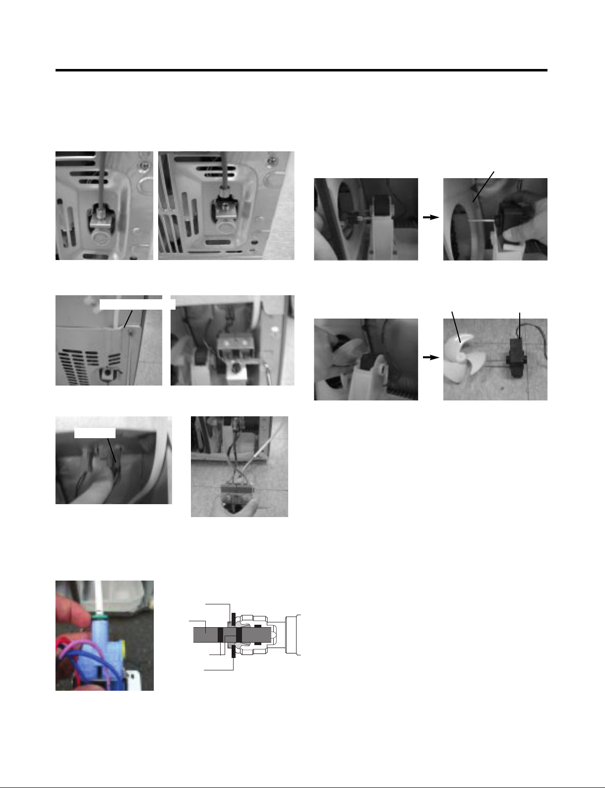
3-20 WATER VALVE DISASSEMBLY METHOD
1) Turn off the water. Then separate the water line from the
valve.
3-21 FAN AND FAN MOTOR DISASSEMBLY
METHOD
1) Using a short screwdriver, loosen one SCREW in DRAIN
PIPE ASSEMBLY and one connected to the MOTOR
COVER.
MOTOR COVER
2) Separate the Cover Back M/C and Valve Screw.
Cover Back M/C
3) Separate the housing and pull out the valve.
Housing
4) Lay a dry towel on the floor and get ready to spill water
from the water filter. Pull out the Cilp. Then press the
collet to separate the tube from the connector and pour
out the water until emptied.
2) Pull and separate the FAN ASSEMBLY and MOTOR
turning counterclockwise based on the MOTOR SHAFT.
FAN ASSEMBLY
The assembly is in the reverse order of the disassembly
and take special care for the following details.
1. Be careful not to bend the tube during assembly.
2. Press the WATER DISPENSER button until water pours
out and check for leakage in the CONNECTOR TUBE (It
differs by the water pressure but usually takes about 2
minutes until water pours out.)
MOTOR
Collet
Tube
Insert Line
Clip
- 15 -
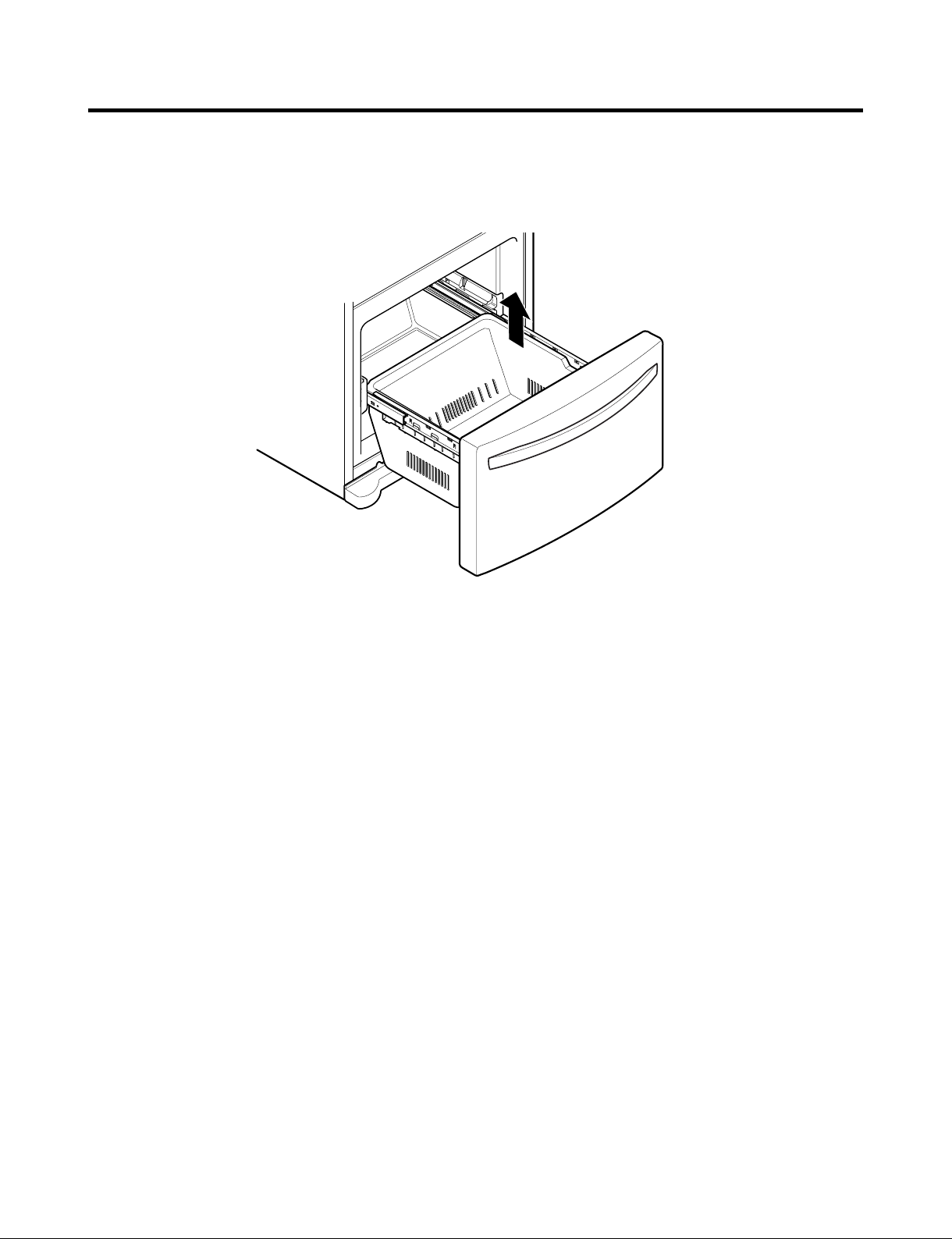
3-22 FREEZER DRAWER
To remove the freezer drawer, pull the drawer open to full extension. Remove the lower DuraBase ®basket by lifting the
basket from the rail system.
- 16 -
4. ADJUSTMENT
4-1 COMPRESSOR
4-1-1 Role
The compressor intakes low temperature and low pressure
gas from the evaporator of the refrigerator and compresses
this gas to high-temperature and high-pressure gas. It then
delivers the gas to the condenser.
4-1-2 Note for Usage
(1) Be careful not to allow over-voltage and over-current.
(2) Do not drop or handle carelessly.
(3) Keep away from any liquid.
If liquid such as oil or water enters the Cover PTC
Compressor may fail due to breakdown of their
insulating capabilities.
(4) Always use the Parts designed for the compressor and
make sure it is properly attached to the compressor.
Parts may appear physically identical but could have
different electrical ratings. Replace parts by part number
and model number. Use only approved substitute parts.
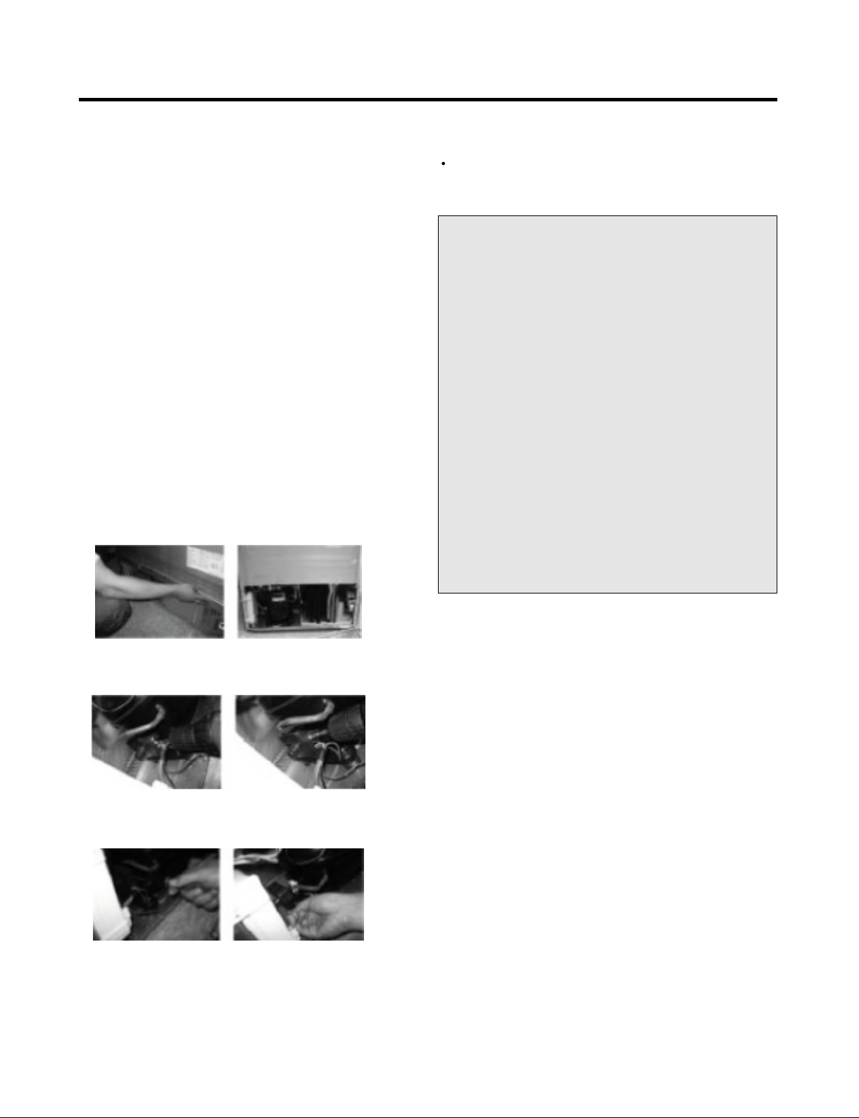
4-1-3 Remove the cover PTC
4-1-4 Compressor protection logic
Since linear Comp conducts linear reciprocating motion,
we have protection logic for compressor, motor and PCB
as the below.
- Stroke Trip
During the operation, if stroke is above the target value,
decrease the target volt by 3V.
- Current Trip
Current trip is set in order to protect compressor
mechanical part and drive from the overcurrent that might
arise during the operation.
Check the current for every 416.7㎲ and if the Trip
exceeds 1.86Arms more than three times at Comp ON,
forcibly stop and restart six minutes later.
- Lock Piston Trip
If stroke is under 5mm even if the current is more than
14Arms, Take it as ‘piston lock’ and restart after 2’30” of
Comp OFF. Check the current and stroke for every
416.7㎲ and if the condition fits more than three times at
Comp ON, The Lock Point Trip occurs.
- IPM fault Trip
It occurs if FO signal received from IPM is LOW. For
every 416.7㎲, check whether FO signal is LOW. The trip
occurs if it is found three times during the five
periods(83ms).
(1) Remove the Cover Back M/C
(2) Loosen two screws on comp base
(3) Use a L-shaped flap tool to pry off the cover
(4) Assembly in reverse order of disassembly
- 17 -
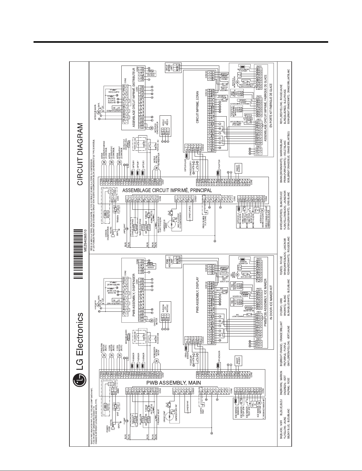
5. CIRCUIT DIAGRAM
- 18 -
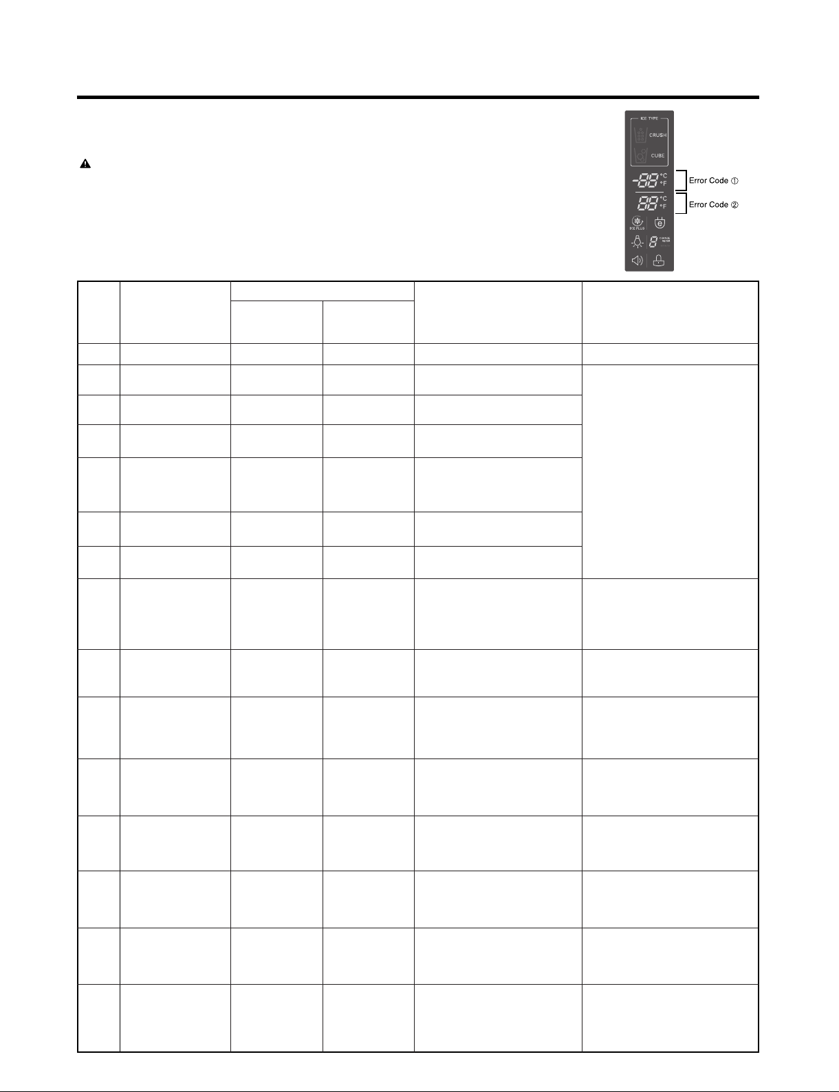
6. TROUBLESHOOTING
6-1 ERROR CODE SUMMARY
WARNING: When you check the Resistance values,
be sure to turn off the power.
And wait for the voltage-discharge sufficiently.
NOTE) 3 hours before the error : Press the Ice Plus button and Freezer button simultaneously
3 hours after the error : All errors, except for "Er rt", "Er SS",
"Er IS(except for Icing sensor)", "Er gF", "Er It" error, are displayed.
"Er IS" which is displayed without input of user is the error of Icing Sensor.
Error Display
Error Detection
NO
1 Normality None Normal operation of Display
2
3
4
5
6
7
8
9
Category
Freezer Sensor
Error
Refrigerator
Sensor Error
Defrosting
Sensor Error
Icing Sensor
Error
Pantry sensor
error
Room Temp
Sensor Error
Ice maker kit
defect
Flow
Meter(Sensor)
Defect
Freezer
Temperature
(Error code
Er FS
Er rS
Er dS
Er IS
Er SS
Er rt
Er It
Er gF
Refrigerator
Temperature
①)
(Error code ②)
Error Generation Factors Remark
Short or Disconnection
of Freezer Sensor
Short or Disconnection
of Refrigerator Sensor
Short or Disconnection
of Defrosting Sensor
Short or disconnection of
the sensor about Ice maker
(Icing sensor, Ice maker
sensor)
Short or Disconnection
of Pantry Sensor
Short or Disconnectoin of
Room temp.sensor
Other Electric system error
such as moter, gear, Hall IC,
operation circuit within I/M kit
Error of flow meter or water
input or low water pressure
Check each sensor and its
connector.
When the ice does not drop
even when the I/M Test S/W
is pressed
(same as model applied
Twisting Ice Maker before)
Error of flow meter or water
input or low water pressure or
flow meter connection
10 Poor Defrosting Er dH
11
12
13
14
15
Abnormality of
BLDC FAN Motor
for Ice Making
Abnormality of
BLDC FAN Motor
for Freezer
Abnormality of
BLDC FAN
MOTOR For
Refrigerator
Abnormality of
BLDC FAN Motor
for Mechanic
Room
Communication
Error
Er IF
Er FF
Er rF
Er CF
Er CO
Even though it is passed
1 hour since then Defrosting,
if Defrosting sensor is not
over 46°F(8°C), it is caused
It is caused when feedback
signal isn’t over 65 seconds
during BLDC FAN motor
operating
It is caused when feedback
signal isn’t over 65 seconds
during BLDC FAN motor
operating
It is caused when feedback
signal isn’t over 65 seconds
during BLDC FAN motor
operating
It is caused when feedback
signal isn’t over 65 seconds
during BLDC FAN motor
operating
Communication Error
between Micom of Main PCB
and Display Micom
- 19 -
Temperature Fuse
Disconnection, Heater
disconnection, DRAIN Jam,
Poor Relay for Heater
Poor BLDC Motor connection,
DRIVE IC, and TR
Poor BLDC Motor connection,
DRIVE IC, and TR
Poor BLDC Motor connection,
DRIVE IC, and TR
Poor BLDC Motor connection,
DRIVE IC, and TR
Poor Communication
connection,Poor TR of
Transmitter and Receiver
Tx/Rx between display and
main board.
NO
Error Detection
Category
Error Display
Freezer
Temperature
(Error code
Refrigerator
Temperature
①)
(Error code ②)
Error Generation Factors
Remark
16
17
18
19
Freezer Shelf
Sensor Error
Freezer Shelf Ice
maker kit defect
Refrigerator Shelf
Icing Sensor Error
Refrigerator Shelf
Ice maker kit
Icing
defect
Er Id
Er IU
Er IS
Er It
Short or disconnection of the
sensor about freezer shelf
Ice maker (Icing sensor, Ice
maker sensor)
Other Electric system error
such as motor, gear, Hall IC,
operation circuit with in
freezer shelf I/M Kit
Short or disconnection of the
sensor about refrigerator
shelf Ice maker (Icing
sensor, Ice maker senseor)
Other Electric system error
such as motor, gear, Hall IC,
operation circuit with in
Check each sensor at it’s
connector.
When the ice does not drop
even when the freezer shelf
I/M Test S/W is pressed
Check each sensor at it’s
connector
When the ice dose not drop
even when the refrigerator
shelf I/M Test S/W is
- 20 -
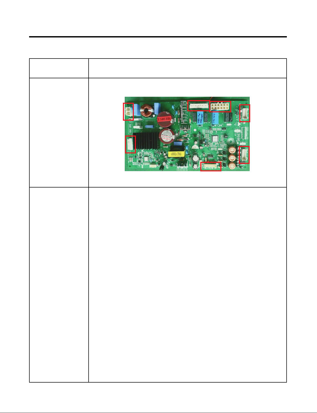
7. PCB PICTURE
7-1 MAIN PCB
P/No & MFG
EBR73304220
(2011.07~)
CON1
CON201
Picture
CON2
CON3
CON5
CON7
CON4
- 21 -
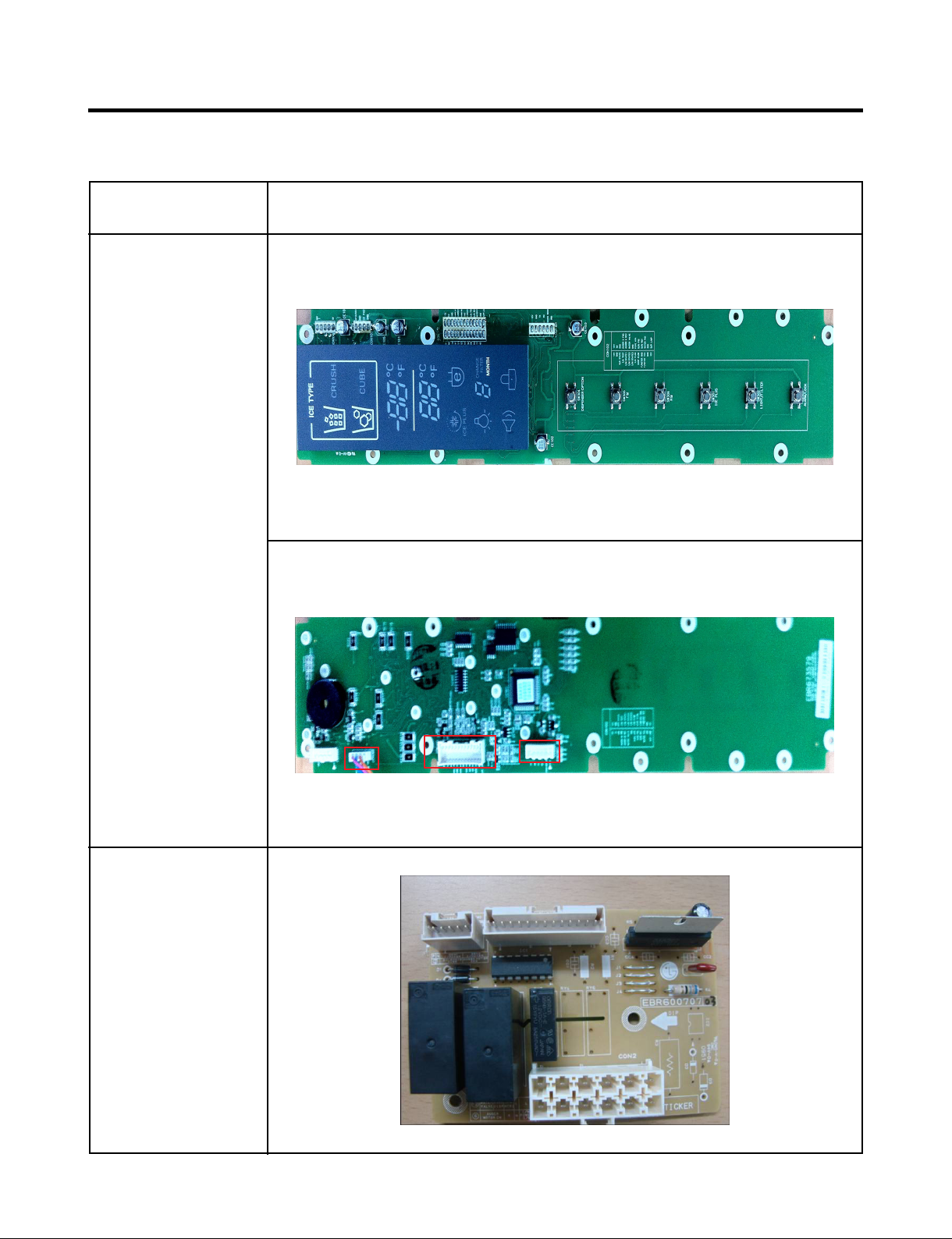
7-2 DISPLAY PCB & SUB PCB
P/No
Display PCB
EBR67357902
(2011.03~)
Picture
Sub PCB
EBR60070707
(2011.03~)
CON103 CON102
- 22 -
CON101
CON2
8.
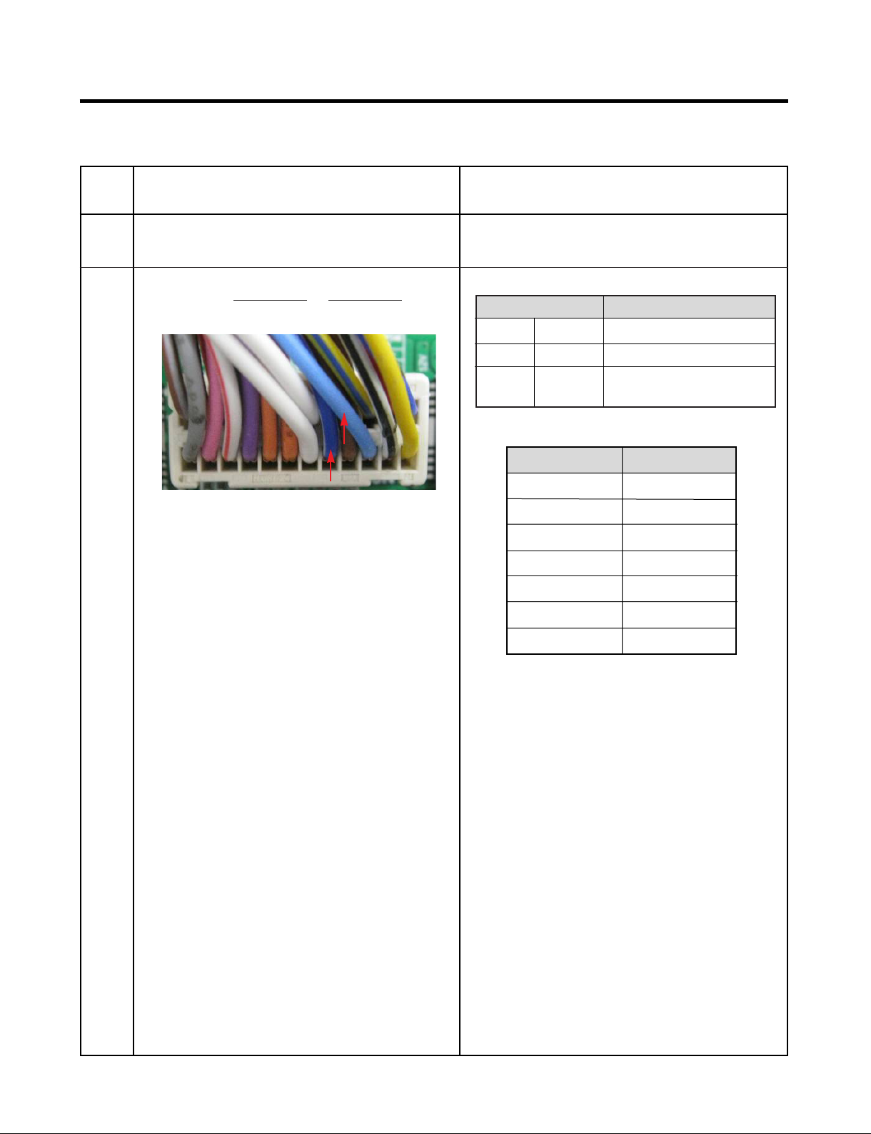
8-1 Freezer Sensor Error (Er FS)
TROUBLESHOOTING WITH ERROR DISPLAY
No
1
2
Checking flow
Check for a loose connection.
Check the Blue/White
CON7 on the main PCB
to Blue/White at
<CON7>
Result & SVC Action
Result SVC Action
Ω
0
OFF
Other
(1) To (2)
-22°F / -30°C
-13°F / -25°C
-4°F / -20°C
5°F / -15°C
14°F / -10°C
Short
Open
Normal
<Temperature table-1>
Change the sensor
Replace the refrigerator
Check the Temp and
resistance (Table-1)
Result
40 ㏀
30 ㏀
23 ㏀
17 ㏀
13 ㏀
23°F / -5°C
32°F / 0°C
※
The sensor is determined by
the temperature.
For example, 23㏀ indicates -4°F.
10 ㏀
8 ㏀
- 23 -
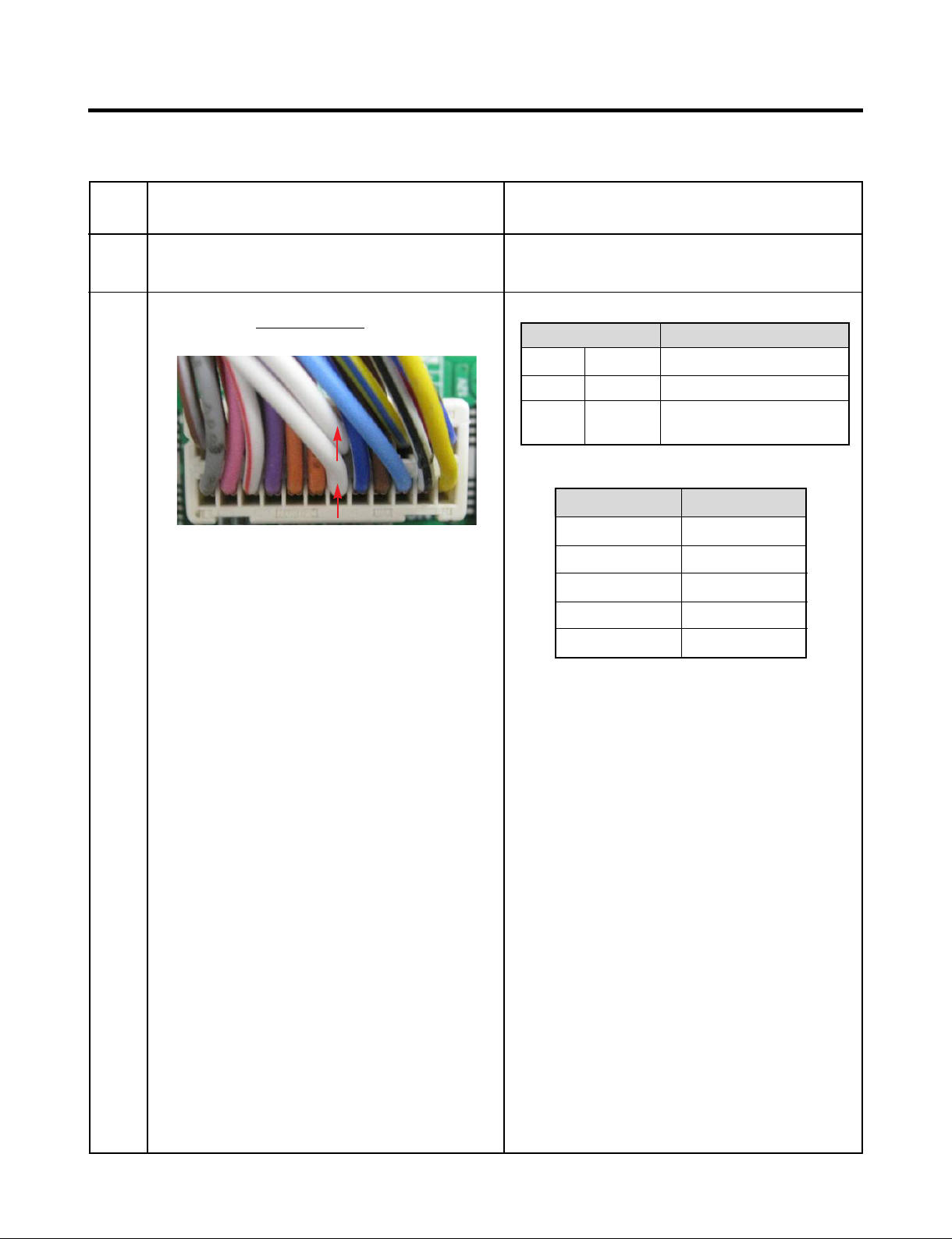
8-2 Refrigerator Sensor Error (Er rS)
No
1
2
Checking flow
Check for a loose connection.
Check the White to White
CON7 on the main PCB
<CON7>
at
Result & SVC Action
Result SVC Action
Ω
0
OFF
Other
Short
Open
Normal
<Temperature table-2>
(1) To (2)
23°F / -5°C
32°F / 0°C
41°F / 5°C
50°F / 10°C
59°F / 15°C
Change the sensor
Replace the refrigerator
Check the Temp and
resistance (Table-2)
Result
38 ㏀
30 ㏀
24 ㏀
19.5 ㏀
16 ㏀
※
The sensor is determined by
the temperature.
For example, 30㏀ indicates 32°F.
- 24 -
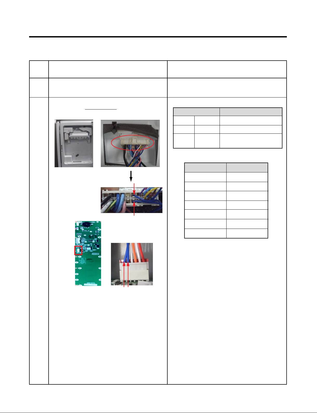
8-3 Icing Sensor Error (Er IS)
No
1
2
Checking flow
Check for a loose connection.
Check the Blue to Blue.
Result & SVC Action
Result SVC Action
Ω
0
OFF
Other
(1) To (2)
-22°F / -30°C
-13°F / -25°C
-4°F / -20°C
5°F / -15°C
14°F / -10°C
Short
Open
Normal
<Temperature table-1>
Change the sensor
Replace the refrigerator
Check the Temp and
resistance (Table-1)
Result
40 ㏀
30 ㏀
23 ㏀
17 ㏀
13 ㏀
CON101
23°F / -5°C
32°F / 0°C
※
The sensor is determined by
the temperature.
For example, 23㏀ indicates -4°F.
<CON101><Display>
10 ㏀
8 ㏀
- 25 -
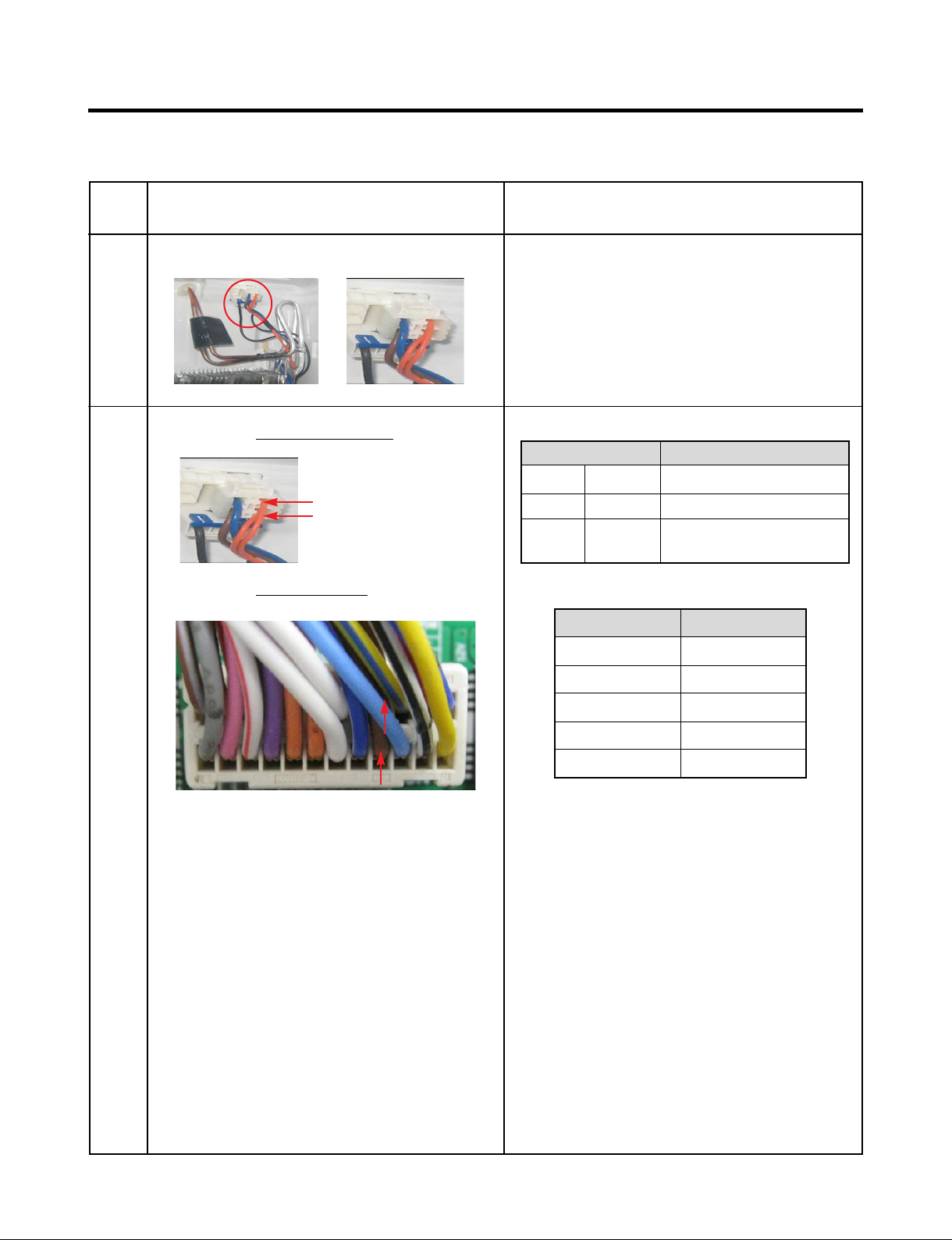
8-4 Defrost Sensor Error (F dS)
No
1
2
Checking flow
Check for a loose connection.
Check the Orange to Orange.
Check the Brown to Brown at
CON7 on the main PCB
Result & SVC Action
Result SVC Action
Ω
0
OFF
Other
Short
Open
Normal
<Temperature table-3>
(1) To (2)
23°F / -5°C
Change the sensor
Replace the refrigerator
Check the Temp and
resistance (Table-3)
Result
38 ㏀
<CON7>
32°F / 0°C
41°F / 5°C
50°F / 10°C
59°F / 15°C
※
The sensor is determined by
the temperature.
For example, 30㏀ indicates 32°F.
30 ㏀
24 ㏀
19.5 ㏀
16 ㏀
- 26 -
 Loading...