

LG LFX28977ST/01, LFX28977WB/01, LFX28977SW/01, LMX28987 SERIES Service Manual
REFRIGERATOR
SERVICE MANUAL
CAUTION
BEFORE SERVICING THE UNIT,
READ THE SAFETY PRECAUTIONS IN THIS MANUAL.
MODEL :
LFX28977ST /01
LFX28977WB /01
LFX28977SW /01
ENC(Engineering Change Number)
LFX28977 /01
Loc No. SPECIFICATIONS
503F
120A
409E
405J
319C
319A
Cover Assembly, Lamp
Duct Assembly, Multi
LED Assembly
LED Assembly
Guide, Fan
Tray, Drip
- 2 -

CONTENTS
SAFETY PRECAUTIONS ....................................................................................................................................................... 2
1. SPECIFICATIONS ............................................................................................................................................................. 3
2. PARTS IDENTIFICATION ................................................................................................................................................. 4
3. DISASSEMBLY ............................................................................................................................................................ 5-17
REMOVING AND REPLACING REFRIGERATOR DOORS ............................................................................................. 5
DOOR ............................................................................................................................................................................. 6-7
DOOR ALIGNMENT .......................................................................................................................................................... 7
FAN AND FAN MOTOR(Evaporator) ................................................................................................................................. 7
DEFROST CONTROL ASSEMBLY ................................................................................................................................... 8
LAMP ................................................................................................................................................................................. 8
MULTI DUCT ..................................................................................................................................................................... 9
MAIN PWB ..........................................................................................................................................................................9
DISPLAY PCB ....................................................................................................................................................................9
ICE BUTTON ASSEMBLY ..................................................................................................................................................9
FUNNEL REPLACEMENT ..................................................................................................................................................9
WATER BUTTON ASSMEBLY .........................................................................................................................................10
DUCT DOOR REPLACEMENT ........................................................................................................................................10
ICE CORNER DOOR REPLACEMENT ............................................................................................................................10
ICEMAKER ASSEMBLY ...................................................................................................................................................10
SUB PWB FOR WORKING DISPENSER ........................................................................................................................11
CAP DUCT MOTOR REPLACEMENT .............................................................................................................................11
AUGER MOTOR COVER .................................................................................................................................................12
HOW TO REMOVE A ICE BIN HOW TO REMOVE A ICE BIN.........................................................................................13
HOW TO INSERT A ICE BIN ............................................................................................................................................13
HOW TO REMOVE AND REINSTALL THE PULLOUT DRAWER ..............................................................................14-15
WATER VALVE DISASSEMBLY METHOD .....................................................................................................................16
FAN AND FAN MOTOR DISASSEMBLY METHOD .........................................................................................................16
PULL OUT DRAWER .......................................................................................................................................................17
4. ADJUSTMENT ........................................................................................................................................................... 18-19
COMPRESSOR ............................................................................................................................................................... 18
Introduction of E-Linear Compressor ...........................................................................................................................18-20
5. CIRCUIT DIAGRAM ........................................................................................................................................................ 21
6. TROUBLESHOOTING ................................................................................................................................................ 22-52
Error Code Summary ....................................................................................................................................................... 22
Troubleshooting With Error.......................................................................................................................................... 23-35
Troubleshooting Else .................................................................................................................................................. 36-54
7. COMPONENT TESTING INFORMATION .................................................................................................................. 55-63
8. TRBOUBLESHOOTING ............................................................................................................................................. 64-68
9. OPERATION PRINCIPLE AND REPAIR METHOD OF ICEMAKER ........................................................................ 69-71
10. DESCRIPTION OF FUNCTION & CIRCUIT OF MICOM ........................................................................................... 72-76
11. EXPLODED VIEW & REPLACEMENT PARTS LIST
SAFETY PRECAUTIONS
Please read the following instructions before servicing your
refrigerator.
1. Unplug the power before handling any elctrical
componets.
2. Check the rated current, voltage, and capacity.
3. Take caution not to get water near any electrical
components.
4. Use exact replacement parts.
5. Remove any objects from the top prior to tilting the
product.
- 3 -
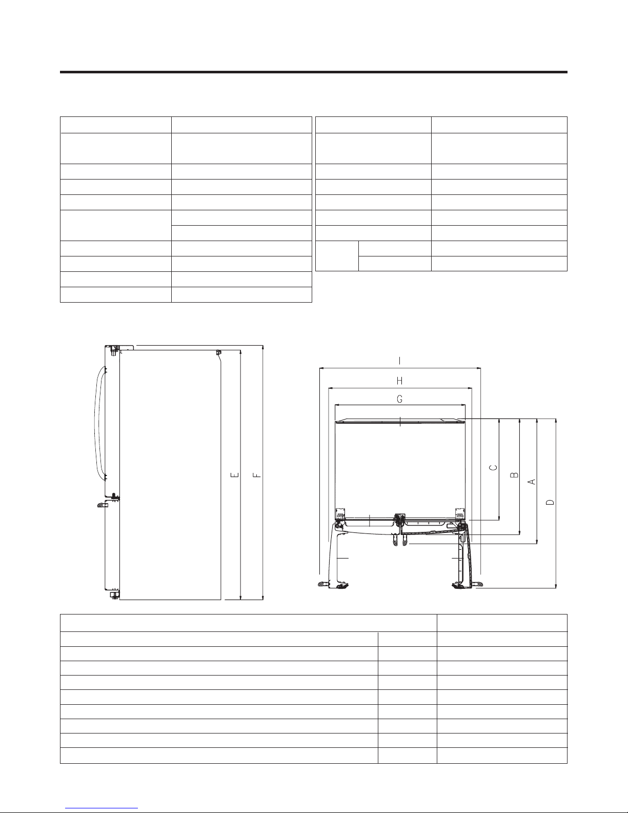
1. SPECIFICATIONS
28 cu.ft.
ITEMS
DOOR DESIGN
DIMENSIONS (inches)
NET WEIGHT (pounds)
COOLING SYSTEM
TEMPERATURE CONTROL
DEFROSTING SYSTEM
DOOR FINISH
HANDLE TYPE
INNER CASE
INSULATION
DIMENSIONS
SPECIFICATIONS
Side Rounded
3
35
/4 X 35 3/8 X 69 3/4 (WXDXH) 28cu.ft.
324(28cu.ft.)
Fan Cooling
Micom Control
Full Automatic
Heater Defrost
Embossed Metal, VCM, Stainless
Bar
ABS Resin
Polyurethane Foam
ITEMS
VEGETABLE TRAY
COMPRESSOR
EVAPORATOR
CONDENSER
REFRIGERANT
LUBRICATING OIL
DEFROSTING DEVICE
LAMP
REFRIGERATOR
FREEZER
SPECIFICATIONS
Clear Drawer Type
Linear
Fin Tube Type
Wire Condenser
R-134a (140 g)
ISO10 (280 ml)
SHEATH HEATER
LED Module(24)
LED Module(12)
Depth w/ Handles
Depth w/ Handles
Depth w/ o Door
Depth (Total with Door Open)
Height to Top of Case
Height to Top of Door Hinge
Width
Width (door open 90 deg. w/o handle)
Width (door open 90 deg. w/ handle)
Description LFX28977** /01
A
B
C
D
E
F
G
H
I
35 3/8 in
32 7/8 in
29 in
47 5/8 in
68 3/8 in
69 3/4 in
35 3/4 in
39 1/4 in
44 1/4 in
- 4 -
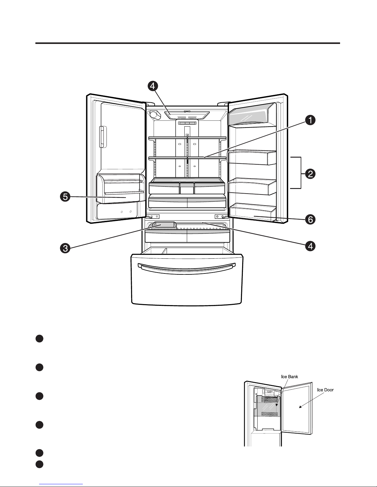
2. PARTS IDENTIFICATION
ADJUSTABLE REFRIGERATOR SHELVING
1
The refrigerator compartment shelves are adjustable to
allow flexibility for storage needs.
GALLON STORAGE BINS
2
Three interchangeable bins can be arranged to suit your
storage needs.
REMOVABLE ICE STORAGE BIN
3
The ice storage bin can be removed to fill ice buckets,
coolers, or pitchers.
LED INTERIOR LAMPS
4
Two separate LED arrays light the freezer and
refrigerator interiors.
5
SHORT N’TALL BIN
6
FIXED DOOR BIN
- 5 -
3. DISASSEMBLY
Correct
Incorrect
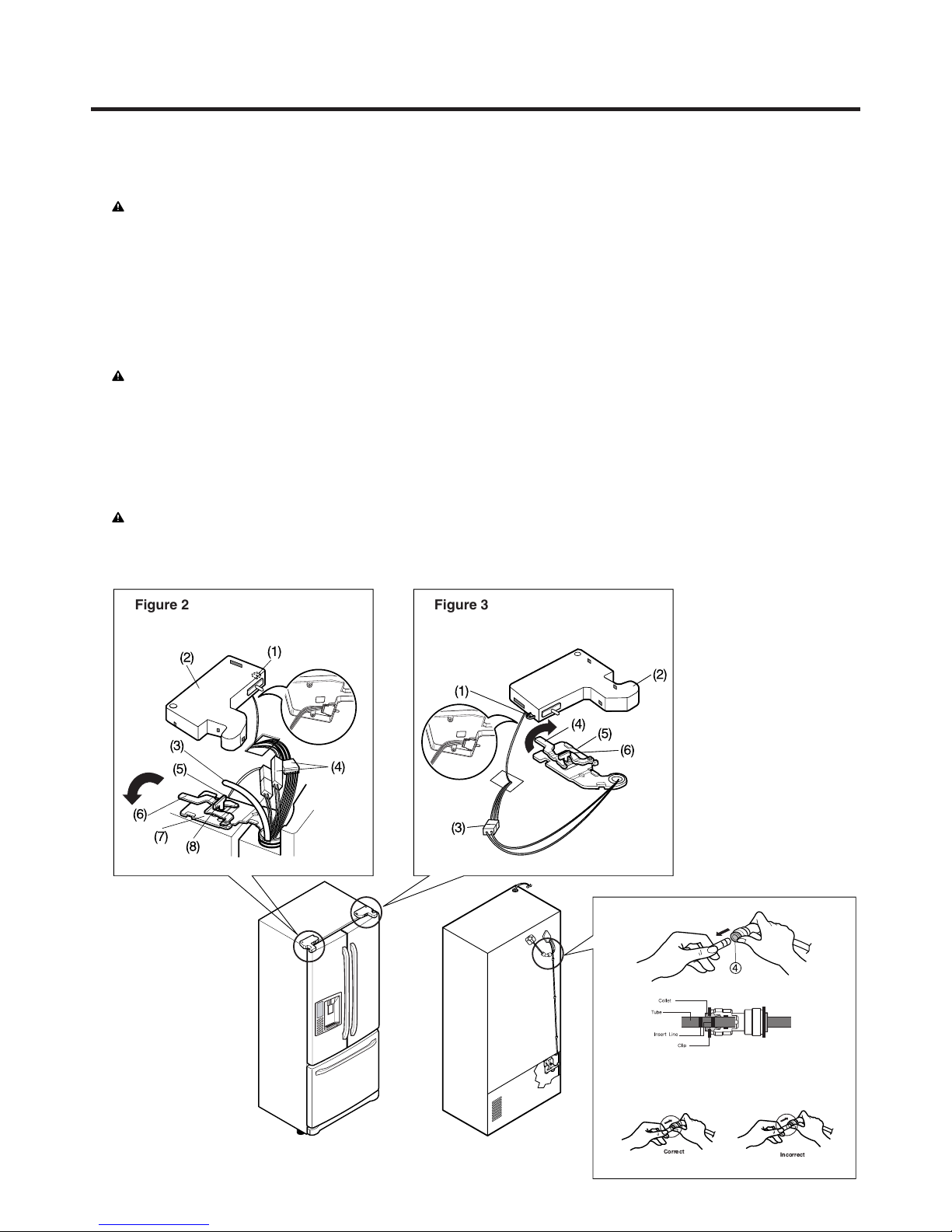
3-1 REMOVING AND REPLACING REFRIGERATOR DOORS
●
Removing Refrigerator Door
CAUTION: Before you begin, unplug the refrigerator. Remove food and bins from doors.
▶
Left Door -FIG. 2
1. Disconnect water supply tube by pushing back on the disconnect ring (4).-FIG. 1
2. Open door. Loosen top hinge cover screw (1).
Use flat tip screwdriver to pry back hooks on front underside of cover (3). Lift up cover.
3. Disconnect door switch wire harness (2). Remove cover.
4. Pull out the tube.
5. Disconnect the three wire harnesses (5). Remove the grounding screw (6).
6. Rotate hinge lever (7) counterclockwise. Lift top hinge (8) free of hinge lever latch (9).
CAUTION: When lifting hinge free of latch, be careful that door does not fall forward.
7. Place door, inside facing up, down onto a non-scratching surface.
▶
Right Door -FIG. 3
1. Open door. Loosen top hinge cover screw (1). Lift up cover (3).
2. Disconnect door switch wire harness (2). Remove cover.
3. Disconnect wire harness (5).
4. Rotate hinge lever (6) clockwise. Lift top hinge (7) free of hinge lever latch (8).
CAUTION: When lifting hinge free of latch, be careful that door does not fall forward.
5. Lift door up from middle hinge pin (9) door.
6. Place door, inside facing up, down onto a non-scratching surface.
Figure 2 Figure 3
Figure 1
1) Insert the tube until you can see only one of
the lines printed on the tube.
2) After inserting, pull the tube to ascertain that
it is secure.
3) Assemble clip.
- 6 -
3-2 DOOR
●
Door Gasket Removal
1. Remove door frame cover
Starting at top of cover and working down, snap cover
out and away from door.
●
Door Gasket Replacement
1. Insert gasket bracket clips
1) Insert gasket bracket edge beneath door frame edge.
2) Turn upper gasket bracket spring so that the spring
ends are in the door channel.
3) Push in clip until you hear it snap securely into place.
Frame Cover
Handle
Figure 1
2. Remove gasket bracket clips
There are two clips on each door. Start bracket removal
near one of the middle clips.
1) Pull gasket back to expose gasket bracket clip and
door frame.
2) Insert a flat tip screwdriver into seam between gasket
bracket and door frame and pry back until clips snap
out.
3) Continue prying back along seam until all clips snap
out.
Gasket
Door
Bracket Clip
Frame
Gasket
Bracket Clip
Spring
Door
Frame
Correct Incorrect
Figure 4
4) Push in remaining clip until you hear it snap securely
into place.
Note: Make sure that no part of gasket bracket edge
protrudes from beneath door frame edge.
2. Insert gasket into channel
1) Snap gasket assembly into the door bracket.
<Inserting the Gasket Assembly into the Bracket Door>
Flat Tip
Screwdriver
3. Remove gasket
Pull gasket free from gasket channel on the three
remaining sides of door.
Gasket
Bracket
Figure 2
Figure 3
- 7 -
Incorrect
Correct
Figure 5
2) Press gasket into channels on the three remaining
sides of door.
3. Replace door frame cover
Starting at top of cover and working down, snap cover
back into door.
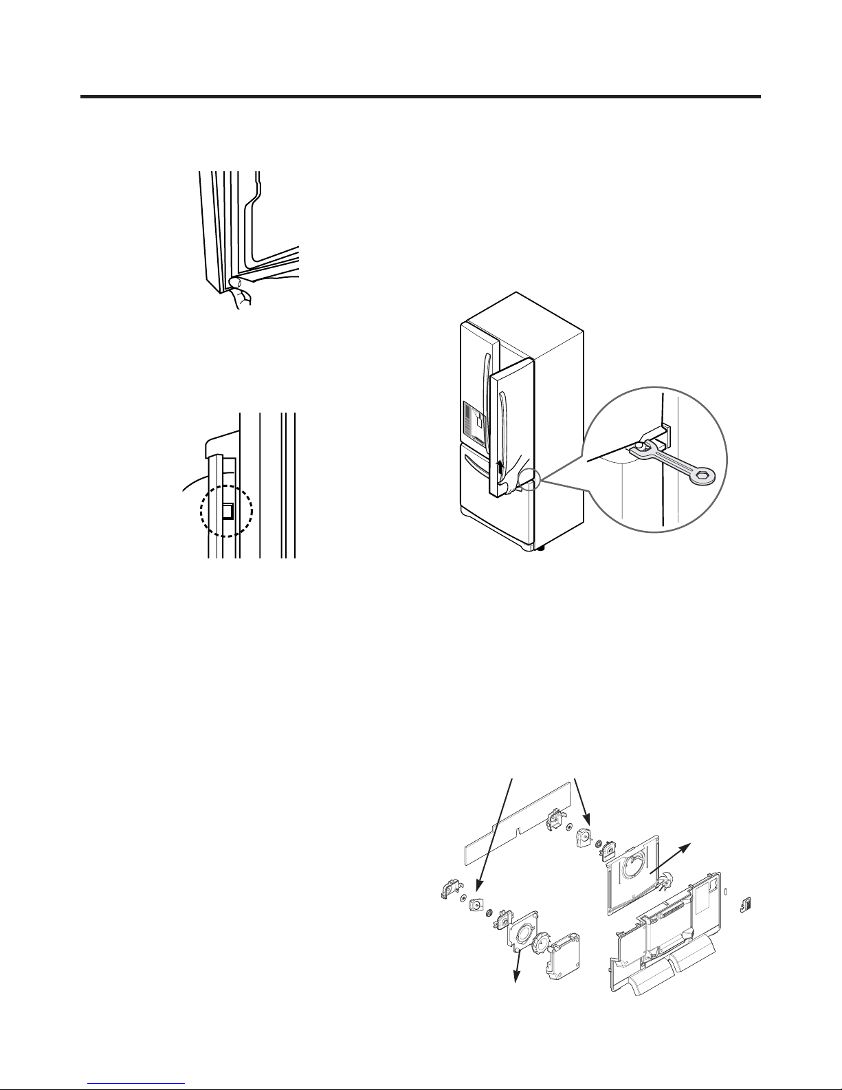
3-3 Door Alignment
If the space between your doors is uneven, follow the
instructions below to align the doors:
Remove the Base Grillie. Turn the leveling legs (CCW) to
raise or (CW) to lower the height of the front of the
refrigerator by using flat blade screw driver or 11/32"
wrench. Use the wrench (Included with the User Manual) to
adjust the bolt in the door hinge to adjust the height. (CCW
to raise or CW to lower the height.)
Figure 6
Figure 7
Figure 8
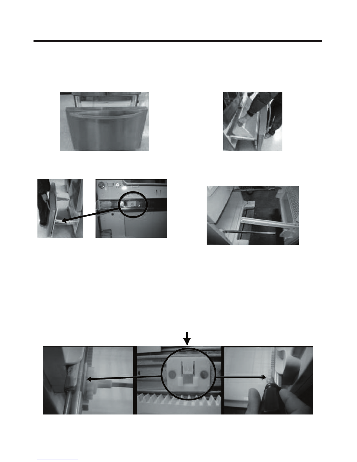
3-4 FAN AND FAN MOTOR(EVAPORATOR)
1. Remove the freezer drawer. (If your refrigerator has an
icemaker, remove the icemaker first)
2. Remove the plastic guide for slides on left side by
unscrewing phillips head screws.
3. Remove the grille by removing four screws and pulling
the grille forward.
4. Remove the Fan Motor assembly by loosening 3 screws
and disassembling the shroud.
5. Pull out the fan and separate the Fan Motor and Bracket.
FAN MOTOR
Shroud
- 8 -
BRACKET
MOTOR
Figure 9

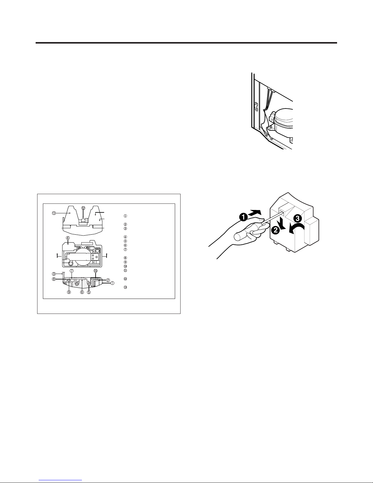
* Ice Fan Scroll Assembly Replacement
1) Remove the plastic guide for slides on left side by
unscrewing phillips head screws.
2) Pull out the cover sensor to disassemble using tools
shown in the figure.
3) Pull out the cover grille to disassemble using tools
shown in the figure.
4) Put your hand into the inside of grille to disassemble
shown in the figure.
5) Disconnect wire harness of the grille
6) Remove the scroll assembly by loosening all screws
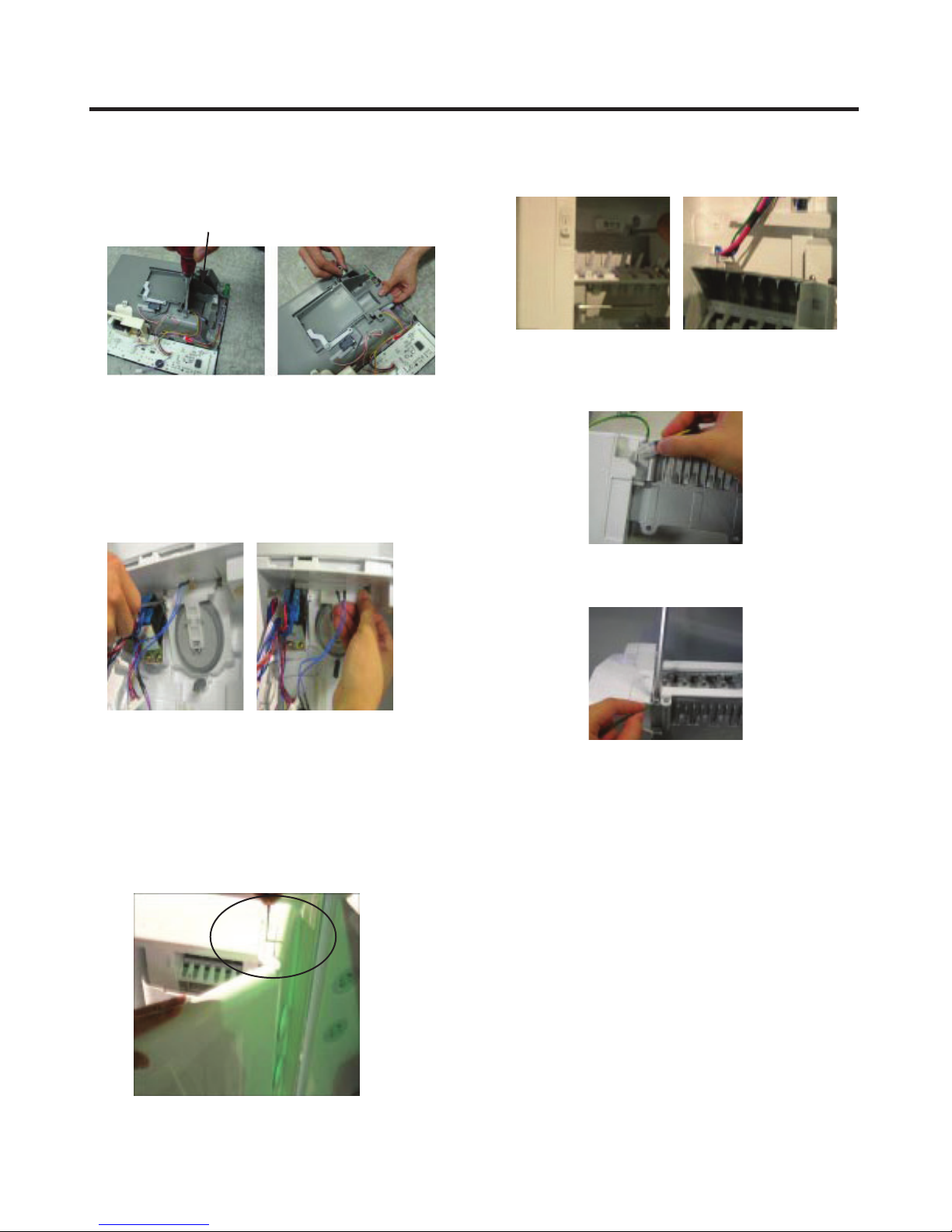
3-6 LAMP
Unplug Refrigerator, or disconnect power at the circuit
breaker.
If necessary, remove top shelf or shelves.
3-6-1 Refrigerator Compartment Lamp
1) Release 2 screws.
2) Hold both ends with your both hands and pull it
downward to remove it.
Figure 12
(1) (2)
(3) (4)
(5) (6)
3-5 DEFROST CONTROL ASSEMBLY
Defrost Control assembly consists of Defrost Sensor and
FUSE-M.
The Defrost Sensor works to defrost automatically. It is
attached to the metal side of the Evaporator and senses its
temperature. At 46F(8°C), it turns the Defrost Heater off.
Fuse-M is a safety device for preventing over-heating of
the Heater when defrosting.
1. Pull out the grille assembly. (Figure 10)
2. Separate the connector with the Defrost Control
assembly and replace the Defrost Control assembly after
cutting the Tie Wrap. (Figure 11)
GRILLE ASSEMBLY
DEFROST-CONTROL
ASSEMBLY
3) To remove the case lamp and cover lamp, release
another 2 screws as following picture.
3) Use a flat tool as shown below to remove the cover
lamp.
Figure 13
4) To remove the LED Assembly, open the Hook part to pull
it out as shown in the following picture.
Case, lamp
Cover, lamp
3-6-2 Freezer Compartment Lamp
1. Unplug refrigerator power cord form outlet.
2. Remove screw with driver.
3. Grasp the cover Lamp, pull the cover downward.
LED, Assembly
Figure 14
Figure 10
Figure 11
Figure 15
- 9 -
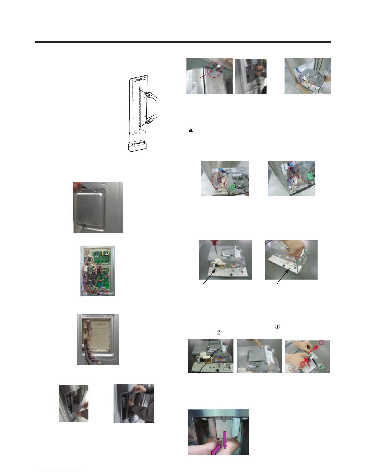
3-7 MULTI DUCT
1. Remove the upper and
lower Caps by using a
flat screwdriver, and
remove 2 screws.
(Figure 16)
2. Disconnect the lead wire
on the bottom position.
3-8 MAIN PWB
1) Loosen the 3 screws on the PWB cover.
2) Remove the PWB cover
Figure 16
3) If nozzle is interfered with button,
push and pull out the bottom of
button.
CAUTION: When replacing the dispensor cover in the
reverse order of removal, be careful that the lead wire
does not come out and the water tube is not pinched by
the dispensor.
4) Rmove the
connected part
of Lead wire.
3-10 DISPLAY PCB
As shown below, remove 1 case PCB fixing screw.
Remove the display PCB fixing screw.
3) Disconnect wire harness and replace the main PWB in
the reverse order of removal.
3-9 DISPENSER
1) Pull out the darin 2) Hold the inner side of
cover dispenser with
both hands at the handle
side to pull it out forward.
Case, PCB
Display PCB
3-11 ICE BUTTON ASSEMBLY
1) Remove the screw fixing the button lever.
2) Push the spring from the hanging hook to remove it.
3) Apply some pressure to the rib in
button in
Button Lever
direction.
direction and lift the
3-12 FUNNEL REPLACEMENT
Pull down and forward.
- 10 -
3-13 WATER BUTTON ASSMEBLY
1) Romove screws.
2) Grasp the Button assembly and lift up.
Button Lever
3-14 DUCT DOOR REPLACEMENT
1) Pull up and out on the dispenser cover to remove.
2) Disconnect the wire harness.
3) Remove the funnel
4) Replace in reverse order.
3-16 ICEMAKER ASSEMBLY
1) Loosen two screws as shown in the first picture.
2) Disconnect the wire harness & ground screw replace
theIcemaker assembly in the reverse order of removal.
3) It separates a ground connection screw.
3-15 ICE CORNER DOOR REPLACEMENT
1) Loosen the front screw as shown in the picture.
2) Lift up the hinge with one hand.
3) Pull out the Ice Corner Door with the other hand.
hinge
- 11 -- 11 -
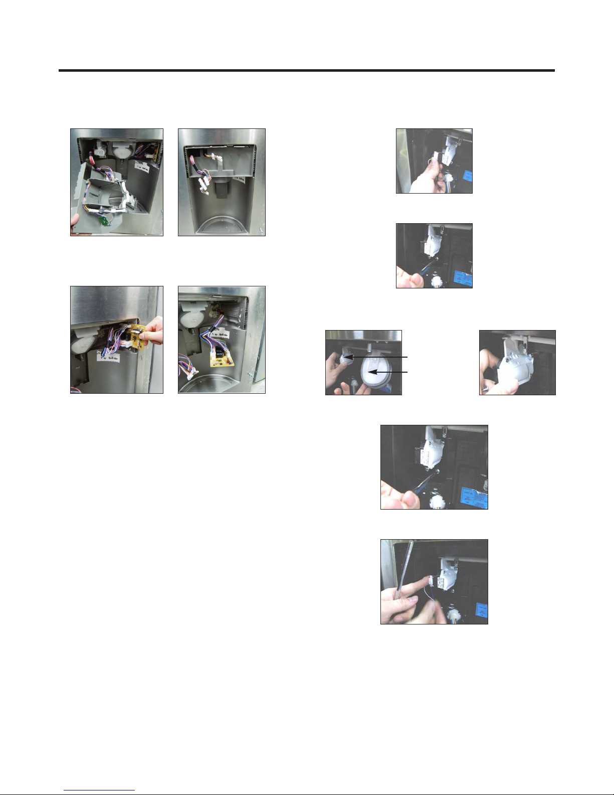
3-17 SUB PWB FOR WORKING DISPENSER
1) Loosen the screw on the sub PWB.
2) Pull the sub PWB down.
3) Disconnect the wire harness and replace the sub PWB in
the reverse order of removal.
3-18 CAP DUCT MOTOR REPLACEMENT
1) Separate the Housing of the Cap Duct Motor.
2) Unscrew 3 screws to disassemble the motor.
3) When replacing to a new Motor, always hold the Duct
Door with your hand to install the Motor.
Cap Duct Motor
Duct Door
4) Assemble on the screws.
5) Contract the Housing.
- 11 -
- 12 -
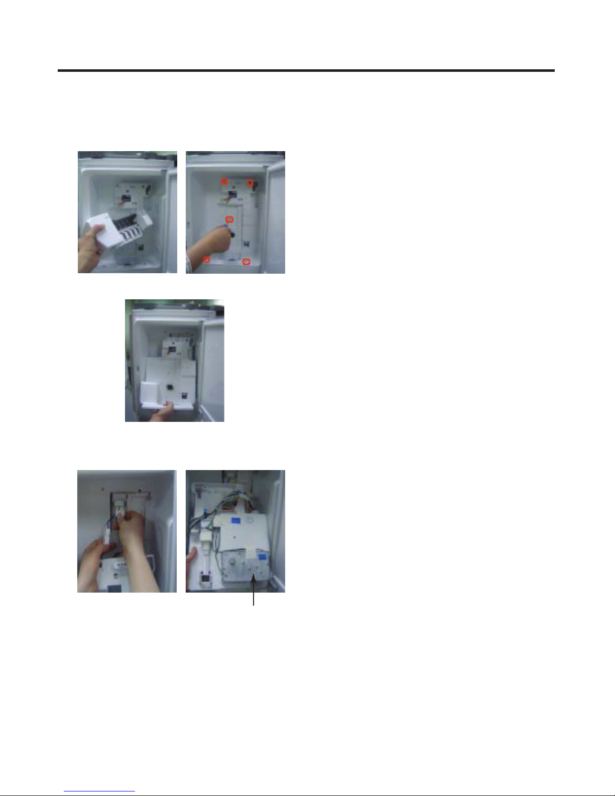
3-19 AUGER MOTOR COVER
1) After removing the icemaker remove the (5) stainless
screws holding the auger motor cover, shown in the
picutres below.
2) Grip the bottom of motor cover assembly and pull out it.
3) Disconnect wire harness of motor cover assembly.
There is a auger motor on the back, as shown in the
picture.
Auger Motor
- 13 -
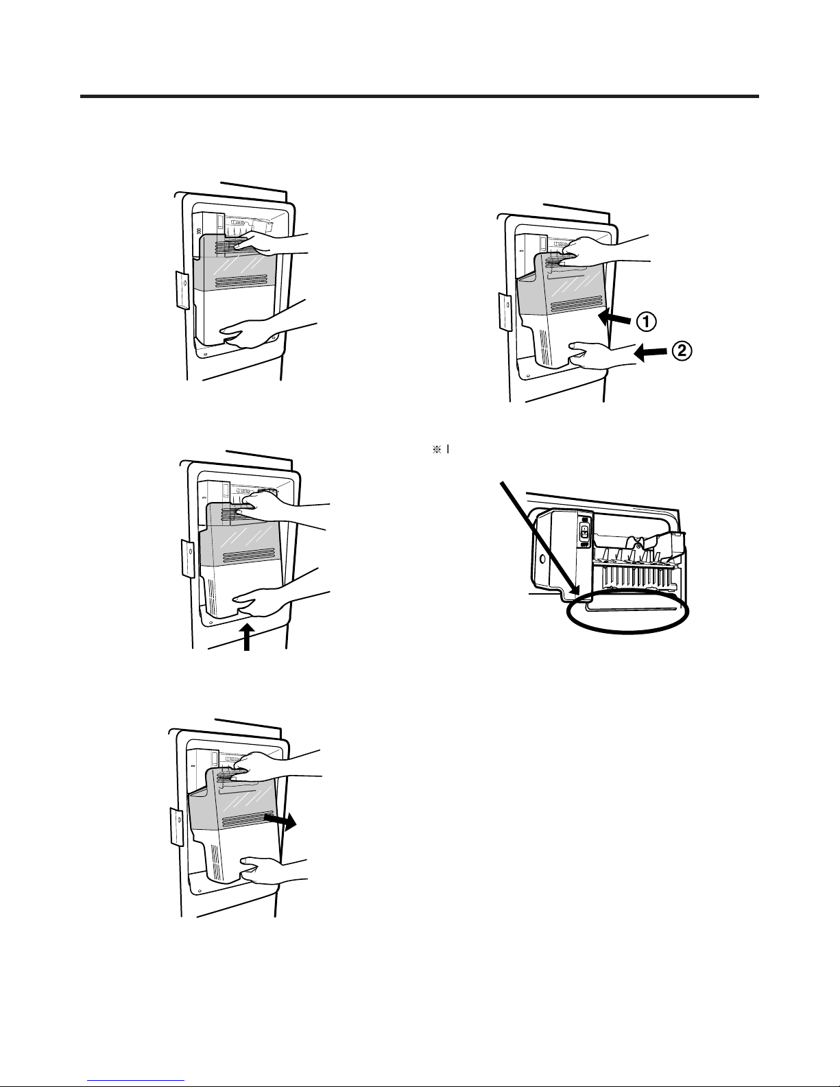
3-20 HOW TO REMOVE A ICE BIN
1) Grip the handles, as shown in the picture.
2) Lift the lower part slightly.
3-21 HOW TO INSERT A ICE BIN
1) Insert the Ice Bin, slightly tilting it to avoid touching the
Icemaker. (especially, icemaker lever)
※ Insert the ice bin carefully avoid contacting the automatic
shut off arm.
3) Take the Ice Bin out slowly.
- 14 -
3-22 HOW TO REMOVE AND REINSTALL THE PULLOUT DRAWER
3-22-1 Follow Steps to Remove
Step 1) Open the freezer door. Step 2) Remove the lower basket.
Step 3) Remove the two screws from the guide rails
(one from each side).
Step 5) First: Remove the gear from the left side first by releasing the tab behind the gear, place a screwdriver between the
gear and the tab and pull up on the gear.
Second: Remove the center rail.
Third: Remove the gear from the right side by following the same steps for the left side.
Step 4) Lift the freezer door up to unhook it from the rail
support and remove.
Pull both rails to full extension.
NOTE: THIS TAB MUST BE PUSHED IN TO RELEASE THE GEAR.
- 15 -

3-22-2 Follow Steps to Reinstall
Step 1) Reinstall the right side gear into the clip.
Step 2) Insert the rail into the right side gear. Gears do not
need to be perpendicular to each other.
Step 4) The rail system will align itself by pushing the rails
all the way into the freezer section.
Pull the rails back out to full extension.
Step 3) Insert the rail into the left side gear, and insert the
gear into the clip.
Step 5) Reinstall the freezer door by inserting the rail tabs
into the guide rail.
Step 6) Reinstall the two screws into the guide rails
(one from each side).
Step 7) Reinstall the lower basket, and close the freezer
door.
- 16 -
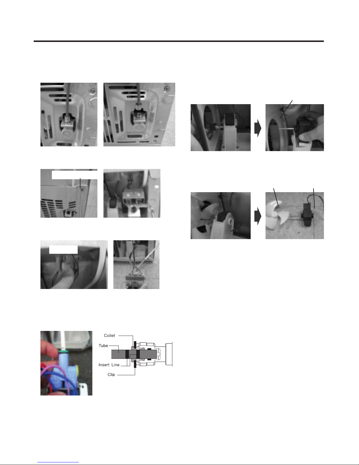
3-23. WATER VALVE DISASSEMBLY METHOD
1) Turn off the water. Then separate the water line from the
valve.
3-24. FAN AND FAN MOTOR DISASSEMBLY
METHOD
1) Using a short screwdriver, loosen one SCREW in DRAIN
PIPE ASSEMBLY and one connected to the MOTOR
COVER.
MOTOR COVER
2) Separate the Mechanical Cover and Valve Screw.
Mechanical Cover
3) Separate the housing and pull out the valve.
Housing
4) Lay a dry towel on the floor and get ready to spill water
from the water filter. Pull out the Cilp. Then press te
collet to separate the tube from the connector and pour
out the water until emptied.
2) Pull and separate the FAN ASSEMBLY and MOTOR
turning counterclockwise based on the MOTOR SHAFT.
FAN ASSEMBLY MOTOR
The assembly is in the reverse order of the disassembly
and take special care for the following details.
1. Be careful not to bend the tube during assembly.
2. Press the WATER DISPENSER button until water pours
out and check for leakage in the CONNECTOR TUBE (It
differs by the water pressure but usually takes about 2
minutes until water pours out.)
- 17 -
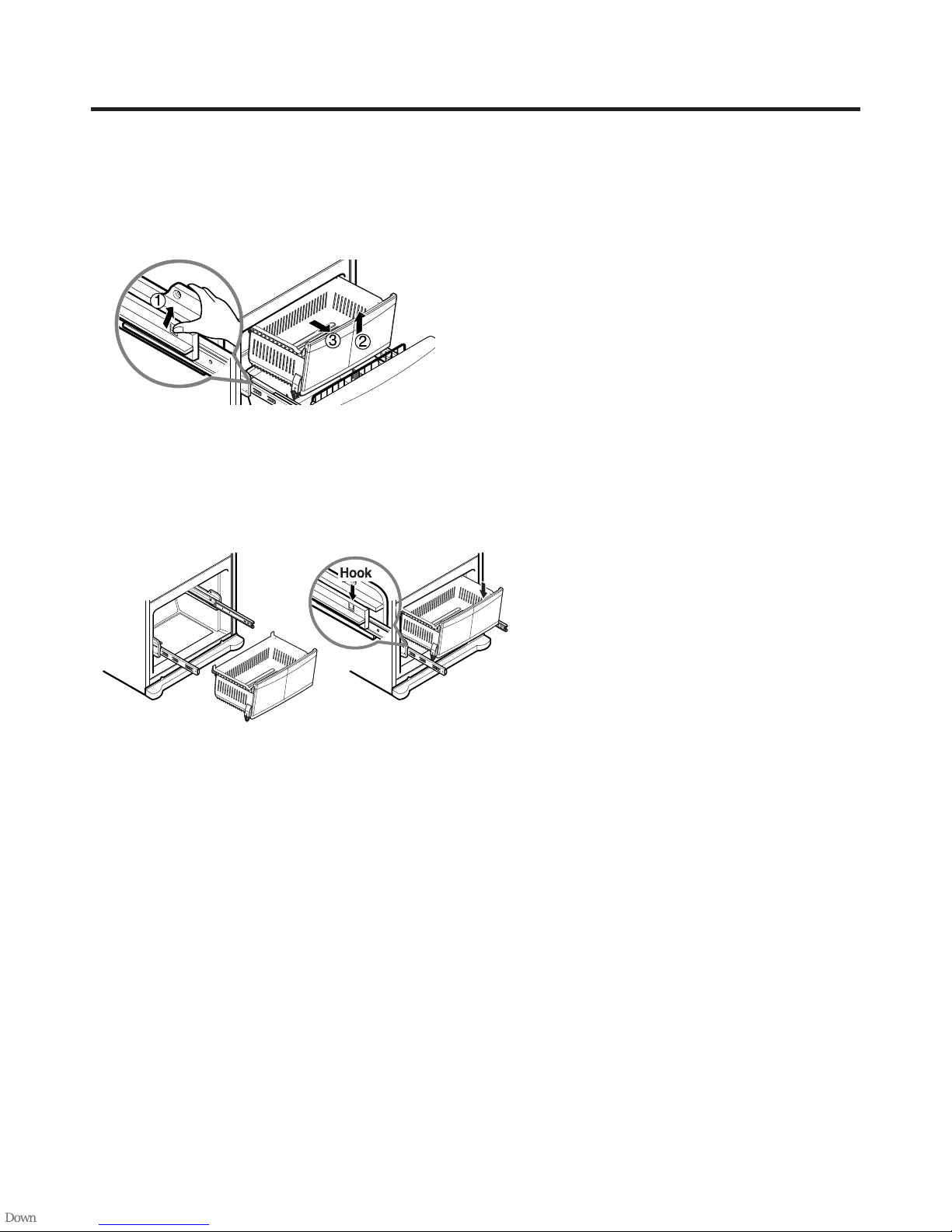
3-25 PULL OUT DRAWER
Hook
To separate the drawer, push the front left and right hooks
in ① direction to pull up and remove.
Then gently lift the gear part of rear left and right side of the
drawer and pull it out in ③ direction.
To install, reposition the gear part of rear left and right side
of the drawer after pulling out both rails as much as
possible, and gently push down both left and right side
while checking the hook on the front part.
- 18 -
4. ADJUSTMENT
PTC STARTER
SEALED
TERMINAL
COMPRESSOR
MOTOR
C
M
S
M
3
6
5
S
N
L1
OVERLOAD PROTECTOR
Resistance Starter Capacitor Running
PTC
22
4-1 COMPRESSOR
4-1-1 Role
The compressor intakes low temperature and low pressure
gas from the evaporator of the refrigerator and compresses
this gas to high-temperature and high-pressure gas. It then
delivers the gas to the condenser.
4-1-2 Composition
The compressor includes overload protection. The PTC
starter and OLP (overload protector) are attached to the
outside of the compressor. Since the compressor is
manufactured to tolerances of 1 micron and is hermetically
sealed in a dust and moisture-free environment, use
extreme caution when performing repairs.
4-1-3 Note for usage
(1) Be careful not to allow over-voltage and over-current.
(2) If compressor is dropped or handled carelessly, poor
operation and noise may result.
(3) Use proper electric components appropriate to the
Particular Compressor in your product.
(4) Keep Compressor dry.
If the Compressor gets wet (in the rain or a damp
environment) and rust forms in the pin of the Hermetic
Terminal, poor operation and contact may result.
(5) When replacing the Compressor, be careful that dust,
humidity, and soldering flux don’t contaminate the inside
of the compressor. Dust, humidity, and solder flux
contaminate the cylinder and may cause noise,
improper operation or even cause it to lock up.
4-2-3 PTC-Applied Circuit Diagram
●
Starting Method for the Motor
4-2-4 Motor Restarting and PTC Cooling
(1) It requires approximately 5 minutes for the pressure to
equalize before the compressor can restart.
(2) The PTC device generates heat during operation.
Therefore, it must be allowed to cool before the
compressor can restart.
4-2-5 Relation of PTC-Starter and OLP
(1) If the compressor attempts to restart before the PTC
device is cooled, the PTC device will allow current to
flow only to the main winding.
(2) The OLP will open because of the over current
condition. This same process will continue (3 to 5 times)
when the compressor attempts to restart until the PTC
device has cooled. The correct OLP must be properly
attached to prevent damage to the compressor.
Parts may appear physically identical but could have
different electrical ratings. Replace parts by part number
and model number. Use only approved substitute parts.
4-2 PTC-STARTER
4-2-1 Composition of PTC-Starter
(1) PTC (Positive Temperature Coefficient) is a no-contact
semiconductor starting device which uses ceramic
material consisting of BaTiO3.
(2) The higher the temperature is, the higher the resistance
value. These features are used as a starting device for
the Motor.
4-2-2 Role of PTC-Starter
(1) The PTC is attached to the Sealed Compressor and is
used for starting the Compressor Motor.
(2) The compressor is a single-phase induction motor.
The starting operation, the PTC allows current flow to
both the start winding and main winding.
4-2-6 Note for Using the PTC-Starter
(1) Be careful not to allow over-voltage and over-current.
(2) Do not drop or handle carelessly.
(3) Keep away from any liquid.
If liquid such as oil or water enters the PTC, PTC
materials may fail due to breakdown of their insulating
capabilities.
(4) If the exterior of the PTC is damaged, the resistance
value may be altered. This can cause damage to the
compressor and result in a no-start or hard-to-start
condition.
(5) Always use the PTC designed for the compressor and
make sure it is properly attached to the compressor.
Parts may appear physically identical but could have
different electrical ratings. Replace parts by part number
and model number. Use only approved substitute parts.
- 19 -
4-3 OLP (OVERLOAD PROTECTOR)
4-3-1 Definition of OLP
(1) OLP (OVERLOAD PROTECTOR) is attached to the
Compressor and protects the Motor by opening the
circuit to the Motor if the temperature rises and
activating the bimetal spring in the OLP.
(2) When high current flows to the Compressor motor, the
Bimetal works by heating the heater inside the OLP, and
the OLP protects the Motor by cutting off the current
flowing to the Compressor Motor.
4-3-2 Role of the OLP
(1) The OLP is attached to the Sealed Compressor used for
the Refrigerator. It prevents the Motor Coil from being
started in the Compressor.
(2) For normal operation of the OLP, do not turn the Adjust
Screw of the OLP in any way.
4-4 TO REMOVE THE COVER PTC
(1) Remove the Cover Back M/C.
(2) Disconnect two housing upper side of comp connected
in.
(3) Loosen two screws on comp base.
(OVERLOAD PROTECTOR cross section)
Customer part
number
12345678
Lot code/
date code
Physical
termination
part number
Electrical
characteristics
part number
330 FBYY -S1 BOX98
Part
No. Name
Base, phenolic
(UL 94 V-0 rated)
Movable arm support, plated steel
Stationary contact support,
plated steel
Heater support, plated steel
Heater, resistance alloy
Disc, thermostatic alloy
Movable arm, spring temper
copper alloy
Contact, movable, silver on copper
Contact, stationary, silver on copper
Slug, plated steel
Cover, polyester
(UL 94 V -0 rated)
Pin connector, plated copper alloy
(To engage 2.33/2.66 mm dia. pin)
Quick-connect terminal, brass,
conforms to UL 310, MEMA
DC-2, DIN 46344
Figure 19
(1) Remove the Cover Back M/C.
(2) Disconnect two housing upper side of comp connected
in.
(3) Loosen two screws on comp base.
- 20 -
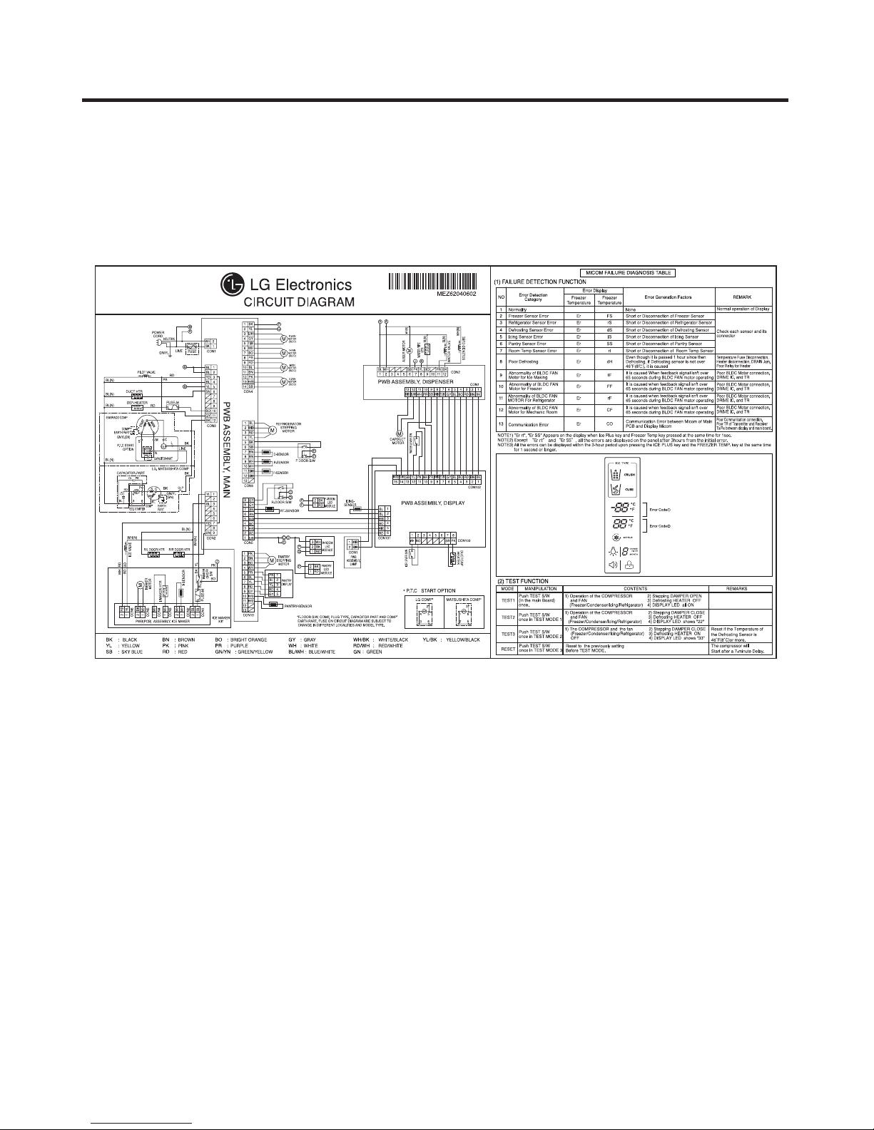
5. CIRCUIT DIAGRAM
- 21 -
6. TROUBLESHOOTING
6-1. Error Code Summary
WARNING: When you check the Resistance values, be sure to turn off the power.
And wait for the voltage-discharge sufficiently.
NOTE) 3 hours before the error : Press the Ice Plus button and Freezer button simultaneously
3 hours after the error : All errors, except for "Er rt" "Er SS" error, are displayed.
Error Detection
NO
1
Freezer Sensor
2
3
4
5
6
7
8
Poor Defrosting Er dH
Abnormality of
BLDC FAN Motor
9
for Ice Making
Error Display
Category
Normality None
Error
Refrigerator
Sensor Error
Defrosting
Sensor Error
Icing Sensor
Error
Pantry sensor
error
Room Temp
Sensor Error
Freezer
Temperature
Er FS
Er rS
Er dS
Er IS
Er SS
Er rt
Er IF
Refrigerator
Temperature
Error Generation Factors Remark
Short or Disconnection
of Freezer Sensor
Short or Disconnection
of Refrigerator Sensor
Short or Disconnection
of Defrosting Sensor
Short or Disconnection
of Icing Sensor
Short or Disconnection
of Pantry Sensor
Short or Disconnectoin of
Room temp.sensor
Even though it is passed
1 hour since then Defrosting,
if Defrosting sensor is not
over 46°F(8°C), it is caused
It is caused when feedback
signal isn’t over 65 seconds
during BLDC FAN motor
operating
Normal operation of Display
Check each sensor and its
connector.
Temperature Fuse
Disconnection, Heater
disconnection, DRAIN Jam,
Poor Relay for Heater
Poor BLDC Motor connection,
DRIVE IC, and TR
Abnormality of
BLDC FAN Motor
10
11
12
13
for Freezer
Abnormality of
BLDC FAN
MOTOR For
Refrigerator
Abnormality of
BLDC FAN Motor
for Mechanic
Room
Communication
Error
Er FF
Er rF
Er CF
Er CO
It is caused when feedback
signal isn’t over 65 seconds
during BLDC FAN motor
operating
It is caused when feedback
signal isn’t over 65 seconds
during BLDC FAN motor
operating
It is caused when feedback
signal isn’t over 65 seconds
during BLDC FAN motor
operating
Communication Error
between Micom of Main PCB
and Display Micom
- 22 -
Poor BLDC Motor connection,
DRIVE IC, and TR
Poor BLDC Motor connection,
DRIVE IC, and TR
Poor BLDC Motor connection,
DRIVE IC, and TR
Poor Communication
connection,Poor TR of
Transmitter and Receiver
Tx/Rx between display and
main board.
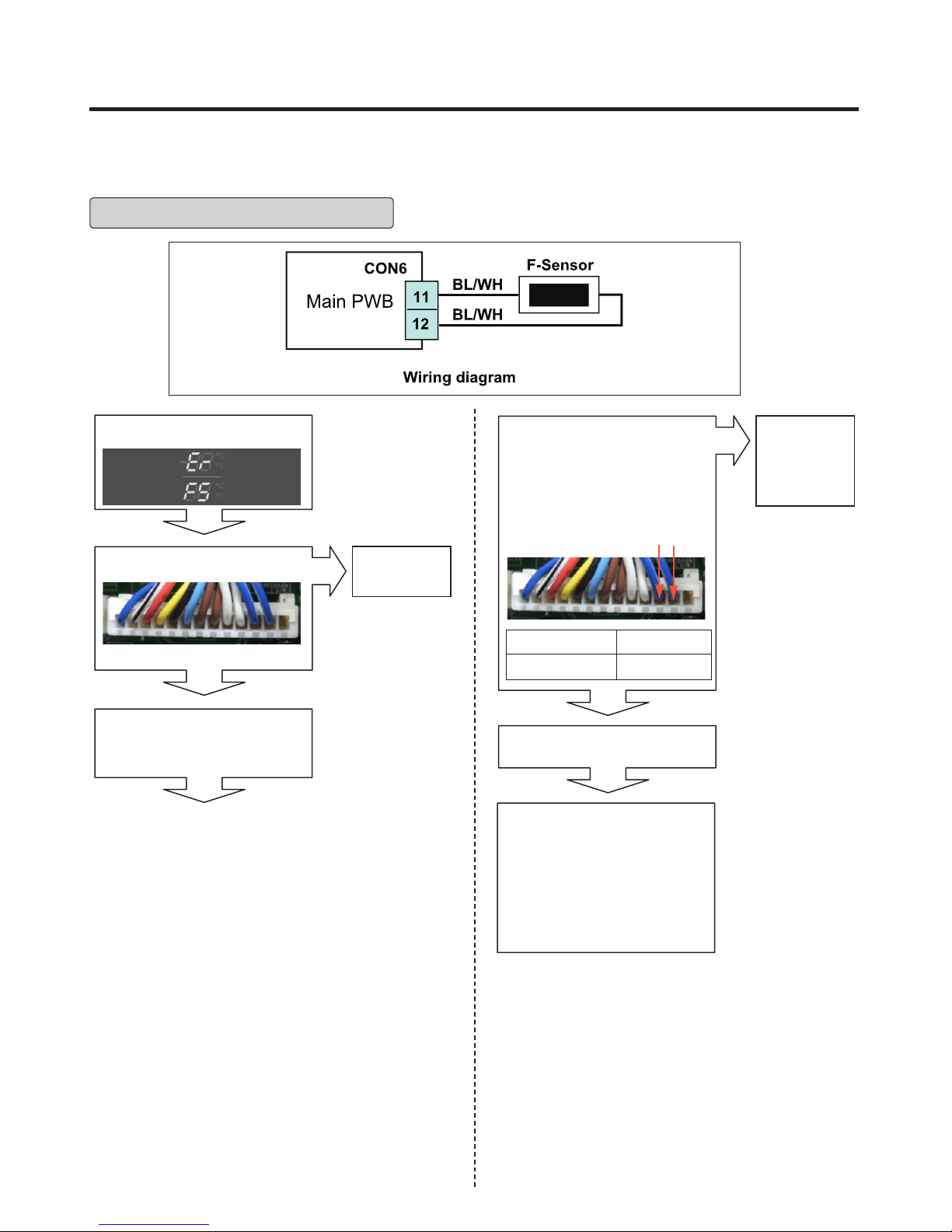
6-2. Troubleshooting With Error
Freezer Sensor Error
Is Er-FS displayed?
Yes
Is the connection loose?
No
Power Off
Tip : To protection of MICOM
Yes
Reconnect
Disconnect CON6 and
measure the value. Is
resistance value between
pins 11 & 12 of CON6 as
below? (BL/WH to BL/WH)
pin11 pin12
Test Point
Pin11 to pin12
Reconnect CON6 and Power
ON
If the ER-FS appears when
you press FREEZER key and
ICE PLUS Key at the same
time, Replace the main PWB.
(Position No:500A)
Otherwise, explain to the
customer!
Result
1.4 ~ 120 ㏀
Yes
No
Replace
F-sensor
(Position
No : 610C)
- 23 -
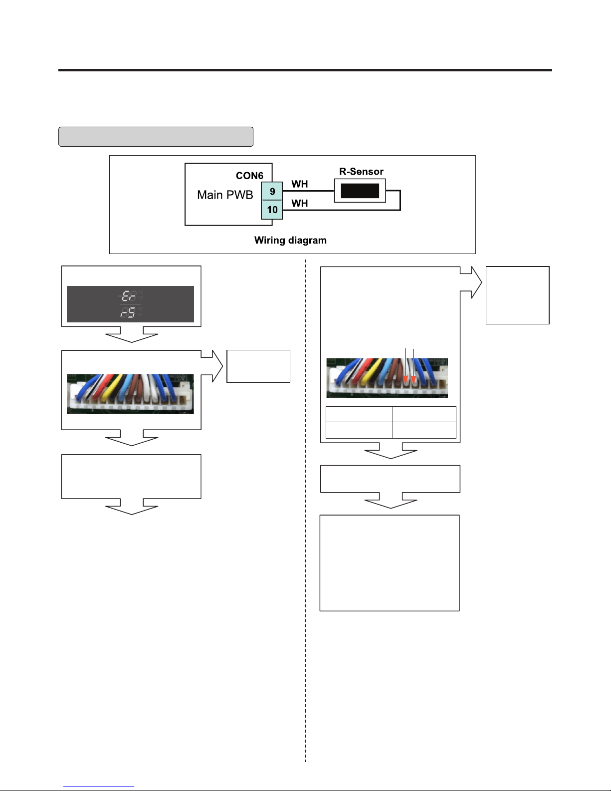
Refrigerator Sensor Error
Is Er-rS displayed?
Yes
Is the connection loose?
No
Power Off
Tip : To protection of MICOM
Yes
Reconnect
Disconnect CON6 and
measure the value. Is
resistance value between
pins 9 & 10 of CON6 as
below? (WH to WH)
pin9 pin10
Test Point
Pin9 to pin10
Reconnect CON6 and Power
ON
If the ER-rS appears when
you press FREEZER key and
ICE PLUS Key at the same
time, Replace the main PWB.
(Position No : 500A)
Otherwise, explain to the
customer!
Result
6 ~ 300 ㏀
Yes
No
Replace
R-sensor
(Position
No : 610B)
- 24 -
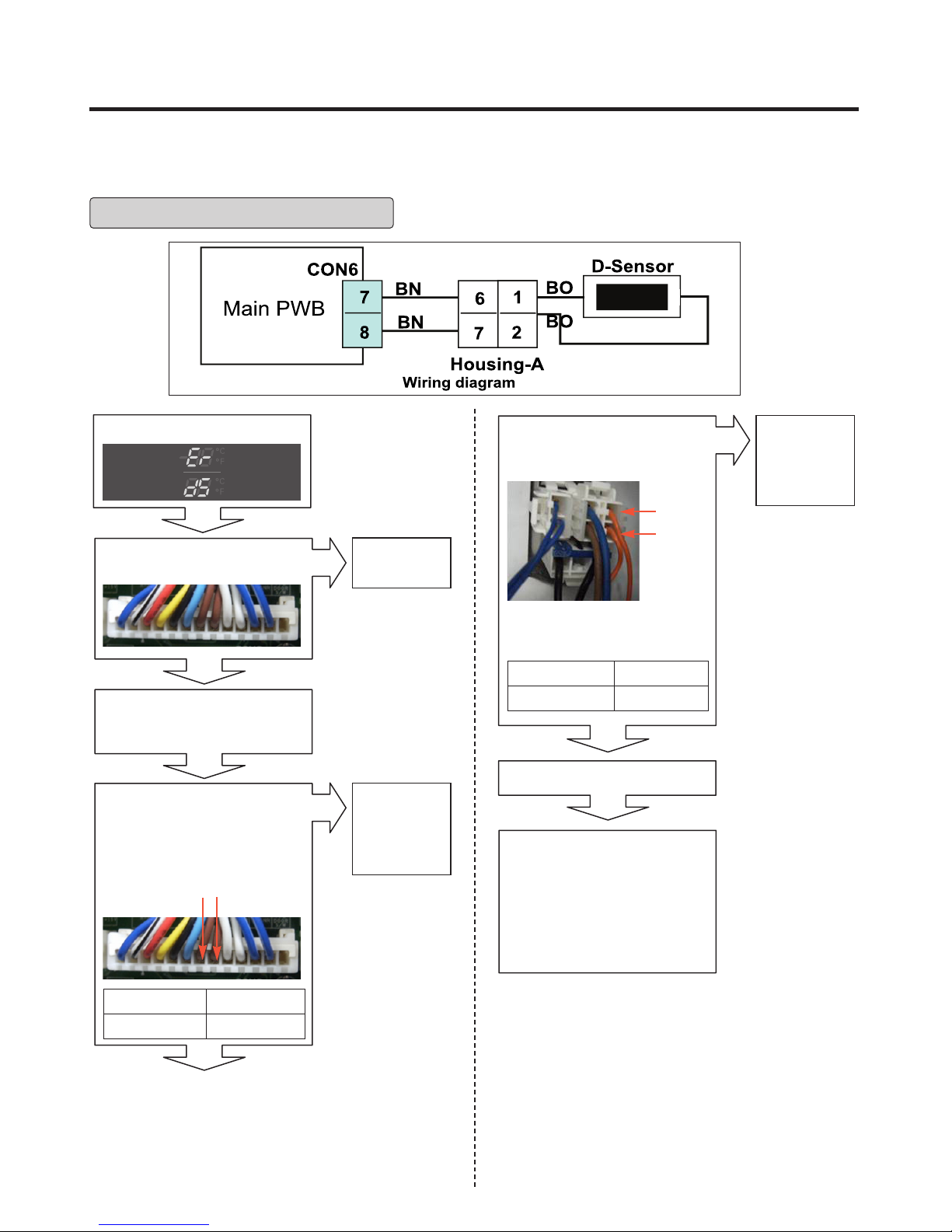
Defrost Sensor Error
Is Er-dS displayed?
Yes
Is the connection loose?
No
Power Off
Tip : To protection of MICOM
Disconnect CON6 and
measure the value. Is
resistance value between
pins 7 & 8 of CON6 as
below? (BN to BN)
pin7
pin8
Yes
No
Reconnect
Replace
D-sensor
(Position
No : 400A)
Is resistance value between
pins 1 & 2 of Housing- A as
below? (BO to BO)
pin1
pin2
Checking Open or Short
of wire
Test Point
Pin1 To pin2
Result
6 ~ 300 ㏀
Yes
Reconnect and Power ON
If the ER-dS appears when
you press FREEZER key and
ICE PLUS Key at the same
time, Replace the main
PWB.(Position No : 500A)
Otherwise, explain to the
customer!
No
Replace
D-sensor
(Position
No :400A)
Test Point
Pin7 to pin8
Result
6 ~ 300 ㏀
Yes
- 25 -
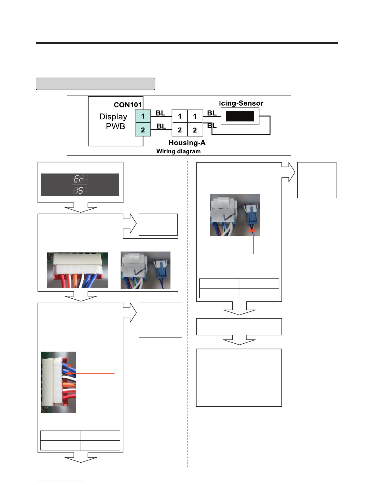
Icing Room Sensor Error
Is Er-IS displayed?
Yes
Is the connection loose?
Display PWB
No
Disconnect CON101 and
measure the value. Is
resistance value between
pins 1 & 2 of CON101 as
below? (BL to BL)
Yes
Inner of Icing door
No
Reconnect
Replace the
Icing-Sensor
(Position
No : 600B)
Is resistance value between
pins 1 & 2 of Housing- A as
below? (BL to BL)
pin1 BL
Checking Open or Short
of wire
Test Point
(1) To (2)
Yes
Reconnect and Power ON
pin2 BL
Result
1.4 ~ 120 ㏀
No
Replace the
Icing-Sensor
(Position
No : 600B)
pin1 BL
pin2 BL
Icing room Sensor Resistance
Test Point
pin1 To pin2
Result
1.4 ~ 120 ㏀
Yes
If the ER-IS appears when
you press FREEZER key and
ICE PLUS Key at the same
time, Replace Display PWB.
(Position No : 501A)
Otherwise, explain to the
customer!
- 26 -
 Loading...