

LG LFX25961 Service Manual
REFRIGERATOR
SERVICE MANUAL
CAUTION
BEFORE SERVICING THE UNIT,
READ THE SAFETY PRECAUTIONS IN THIS MANUAL.
MODEL : LFX25961**
COLOR : STAINLESS (ST)
ILLUMINA (AV)
WESTERN BLACK (SB)
SUPER WHITE (SW)

CONTENTS
SAFETY PRECAUTIONS ....................................................................................................................................................... 2
1. SPECIFICATIONS ............................................................................................................................................................. 3
2. PARTS IDENTIFICATION ................................................................................................................................................. 4
3. DISASSEMBLY ............................................................................................................................................................ 5-14
REMOVING AND REPLACING REFRIGERATOR DOORS ............................................................................................. 5
DOOR ............................................................................................................................................................................. 6-7
DOOR ALIGNMENT ........................................................................................................................................................... 7
FAN AND FAN MOTOR(EVAPORATOR) ......................................................................................................................... 7
DEFROST CONTROL ASSEMBLY ................................................................................................................................... 8
LAMP ................................................................................................................................................................................. 8
MULTI DUCT ..................................................................................................................................................................... 9
MAIN PWB ..........................................................................................................................................................................9
DISPENSER .......................................................................................................................................................................9
DISPLAY PWB REPLACEMENT ....................................................................................................................................... 9
SUB PWB FOR DISPENSER .......................................................................................................................................... 10
DUCT DOOR REPLACEMENT ........................................................................................................................................10
ICE CORNER DOOR REPLACEMENT ............................................................................................................................10
ICEMAKER ASSEMBLY ...................................................................................................................................................10
AUGER MOTOR COVER ................................................................................................................................................ 11
HOW TO REMOVE A DOOR ICE BIN ............................................................................................................................ 12
HOW TO INSERT A DOOR ICE BIN ................................................................................................................................12
HOW TO REMOVE AND REINSTALL THE PULLOUT DRAWER ............................................................................. 13-14
WARWE VALVE DISASSEMBLY METHOD ....................................................................................................................15
FAN AND FAN MOTOR DISASSEMBLY METHOD..........................................................................................................15
PULL OUT DRAWER ........................................................................................................................................................16
4. ADJUSTMENT ........................................................................................................................................................... 17-18
COMPRESSOR ............................................................................................................................................................... 17
PTC-STARTER ................................................................................................................................................................ 17
OLP(OVERLOAD PROTECTOR) .................................................................................................................................... 18
TO REMOVE THE COVER PTC ..................................................................................................................................... 18
5. CIRCUIT DIAGRAM ........................................................................................................................................................ 19
6. TROUBLESHOOTING ............................................................................................................................................... 20-24
7. OPERATION PRINCIPLE AND REPAIR METHOD OF ICEMAKER ........................................................................ 25-27
8. DESCRIPTION OF FUNCTION & CIRCUITS OF MICON ......................................................................................... 28-43
9. EXPLODED VIEW & REPLACEMENT PARTS LIST ................................................................................................ 44-50
SAFETY PRECAUTIONS
Please read the following instructions before servicing your
refrigerator.
1. Unplug the power before handling any elctrical componets.
2. Check the rated current, voltage, and capacity.
3. Take caution not to get water near any electrical components.
4. Use exact replacement parts.
5. Remove any objects from the top prior to tilting the product.
- 2 -
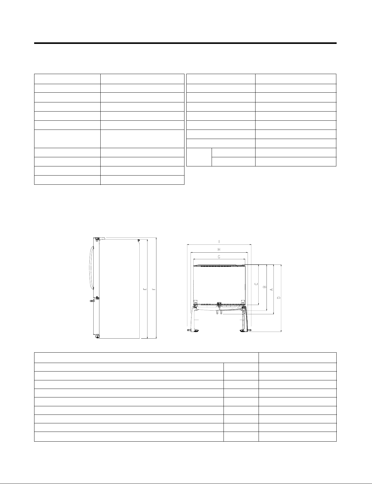
1. SPECIFICATIONS
25 cu.ft.
ITEMS
DOOR DESIGN
DIMENSIONS (inches)
NET WEIGHT (pounds)
COOLING SYSTEM
TEMPERATURE CONTROL
DEFROSTING SYSTEM
DOOR FINISH
HANDLE TYPE
INNER CASE
INSULATION
DIMENSIONS
SPECIFICATIONS
Side Rounded
3
35
/4 X 34 1/4 X 69 3/4 (WXDXH) 25cu.ft
324.18 (25cu.ft)
Fan Cooling
Micom Control
Full Automatic
Heater Defrost
Embossed Metal, VCM, Stainless
Bar
ABS Resin
Polyurethane Foam
ITEMS
VEGETABLE TRAY
COMPRESSOR
EVAPORATOR
CONDENSER
REFRIGERANT
LUBRICATING OIL
DEFROSTING DEVICE
LAMP
REFRIGERATOR
FREEZER
SPECIFICATIONS
Opaque Drawer Type
Recipro
Fin Tube Type
Wire Condenser
R-134a (145 g)
ISO10 (280 ml)
SHEATH HEATER
60W (2EA)
60W (1EA)
Depth w/ Handles
Depth w/o Handles
Depth w/o Door
Depth (Total with Door Open)
Height to Top of Case
Height to Top of Door Hinge
Width
Width (door open 90 deg. w/o handle)
Width (door open 90 deg. w/ handle)
Description LFX25961**/02
A
B
C
D
E
F
G
H
I
34 1/4 in.
31 3/4 in.
27 7/8 in.
46 1 /2 in.
68 3/8 in.
69 3/4 in.
35 3/4 in.
39/1/4 in.
44 1/4 in.
- 3 -
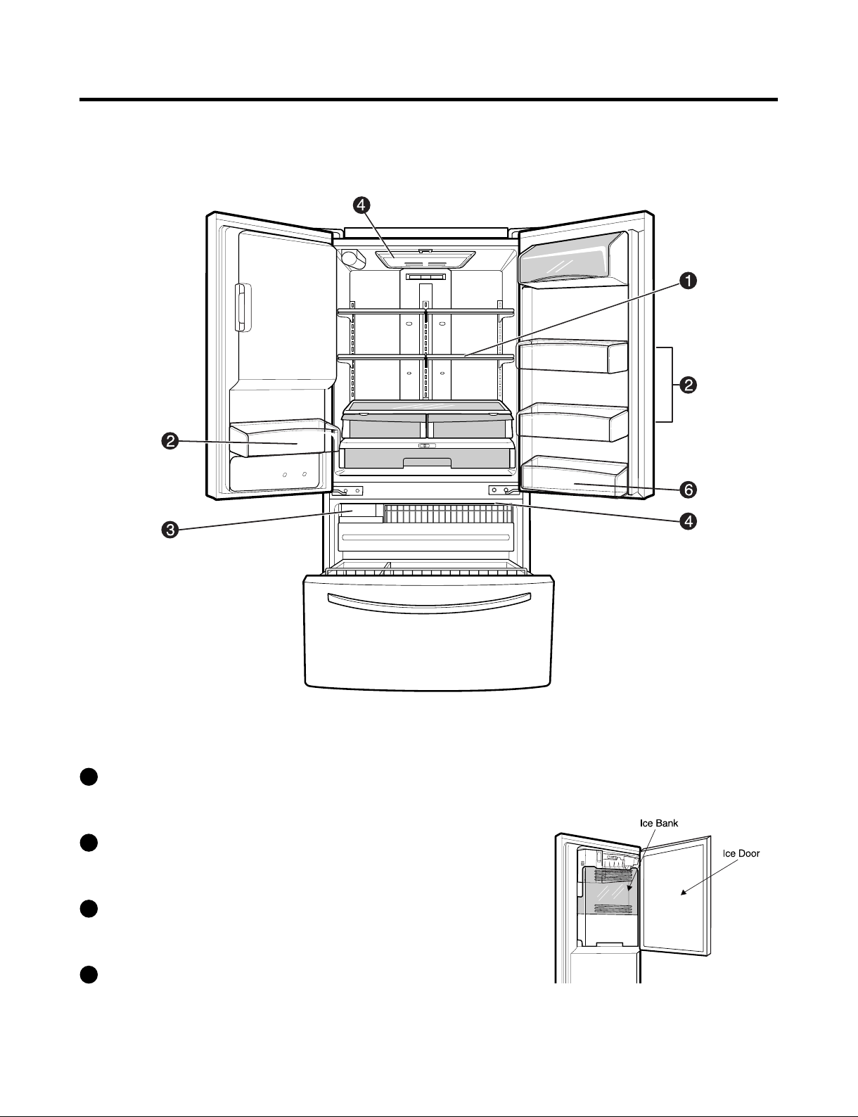
2. PARTS IDENTIFICATION
ADJUSTABLE REFRIGERATOR SHELVING
1
The refrigerator compartment shelves are adjustable to
allow flexibility for storage needs.
MODULAR DOOR BINS
2
Three interchangeable bins can be arranged to suit your
storage needs.
REMOVABLE ICE STORAGE BIN
3
The ice storage bin can be removed to fill ice buckets,
coolers,or pitchers.
INTERIOR LAMPS
4
- 4 -
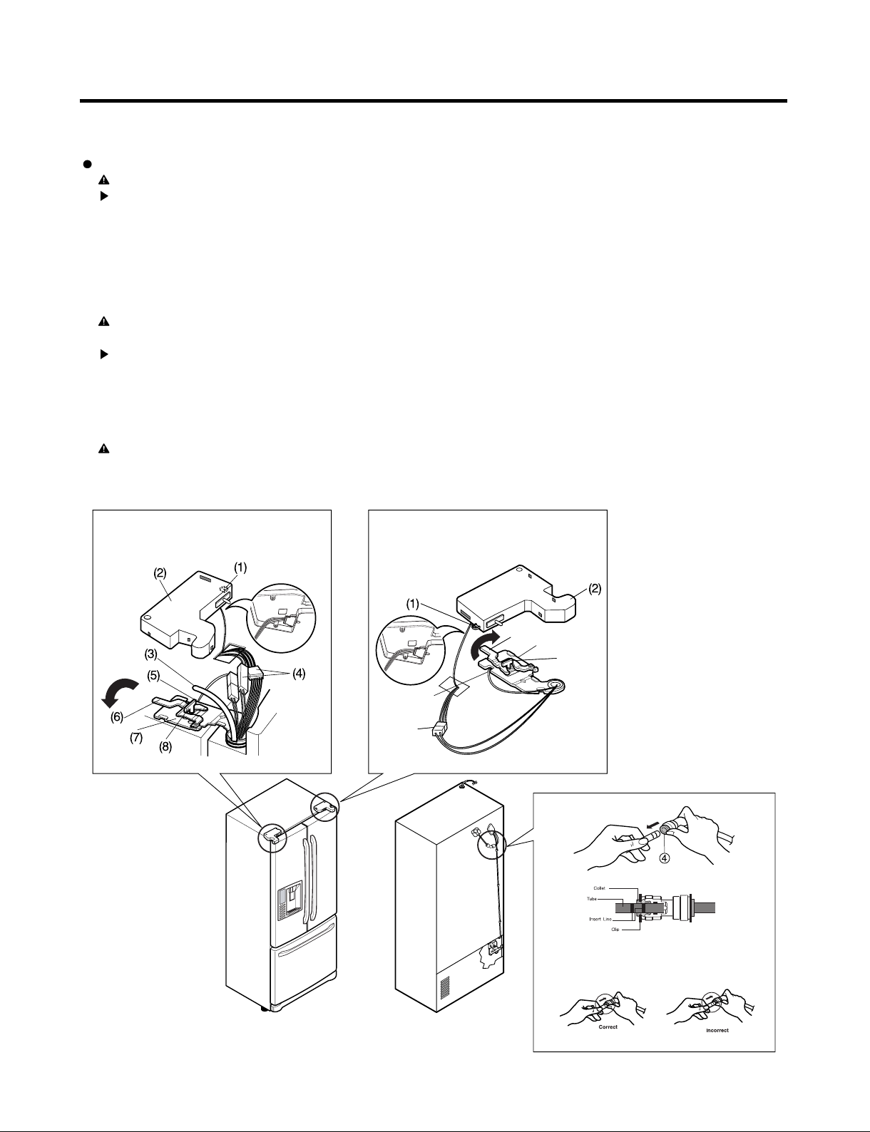
3. DISASSEMBLY
(5)
(6)
(7)
(4)
(3)
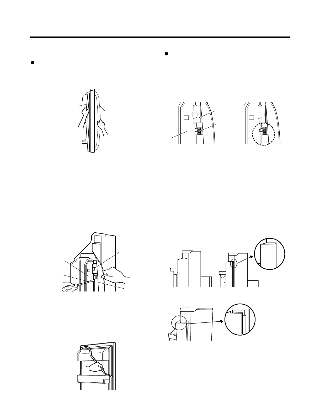
3-1 REMOVING AND REPLACING REFRIGERATOR DOORS
Removing Refrigerator Door
CAUTION : Before you begin, unplug the refrigerator. Remove food and bins from doors.
Left Door -FIG. 2
1. Disconnect water supply tube by pushing back on the disconnect ring (4).-FIG. 1
2. Open door. Loosen top hinge cover screw (1).
Use flat tip screwdriver to pry back hooks on front underside of cover (3). Lift up cover.
3. Disconnect door switch wire harness (2).
4. Pull out the tube..
5. Disconnect the three wire harnesses (5). Remove the grounding screw (6).
6. Rotate hinge lever (7) counterclockwise. Lift top hinge (8) free of hinge lever latch (9).
CAUTION : When lifting hinge free of latch, be careful that door does not fall forward.
7. Place door, inside facing up, down onto a non-scratching surface.
Right Door -FIG. 3
1. Open door. Loosen top hinge cover screw (1). Lift up cover (2).
2. Disconnect door switch wire harness. Remove cover.
3. Disconnect wire harness (3).
4. Remove the grounding screw (4).
5. Rotate hinge lever (5) clockwise. Lift top hinge (6) free of hinge lever latch (7).
CAUTION : When lifting hinge free of latch, be careful that door does not fall forward.
6. Lift door up from middle hinge pin door.
7. Place door, inside facing up, down onto a non-scratching surface.
Figure 2 Figure 3
Figure 1
- 5 -
1)Insert the tube until you can see only one of the lines
printed on the tube.
2)After inserting, pull the tube to ascertain that it is secure.
3)Assemble clip.
3-2 DOOR
Removing Refrigerator Door
1. Remove door frame cover
Starting at top of cover and working down, snap cover
out and away from door.
Door Gasket Replacement
1. Insert gasket bracket clips
1) Insert gasket bracket edge beneath door frame edge.
2) Turn upper gasket bracket spring so that the spring
ends are in the door channel.
3) Push in clip until you hear it snap securely into place.
Frame Cover
Handle
Figure 1
2. Remove gasket bracket clips
There are two clips on each door. Start bracket removal
near one of the middle clips.
1) Pull gasket back to expose gasket bracket clip and
door frame.
2) Insert a flat tip screwdriver into seam between gasket
bracket and door frame and pry back until clips snap
out.
3) Continue prying back along seam until all clips snap
out.
Gasket
Door
Frame
Bracket Clip
Gasket
Bracket Clip
Spring
Door
Frame
4) Push in remaining clip until you hear it snap securely
Note: Make sure that no part of gasket bracket edge
2. Insert gasket into channel
1) Snap gasket assembly into the door bracket.
<Inserting the Gasket Assembly into the Bracket Door>
Correct Incorrect
Figure 4
into place.
protrudes from beneath door frame edge.
Flat Tip
Screwdriver
3. Remove gasket
Pull gasket free from gasket channel on the three
remaining sides of door.
Gasket
Bracket
Figure 2
Figure 3
Correct
Figure 5
Incorrect
- 6 -
2) Press gasket into channels on the three remaining sides
of door.
Figure 6
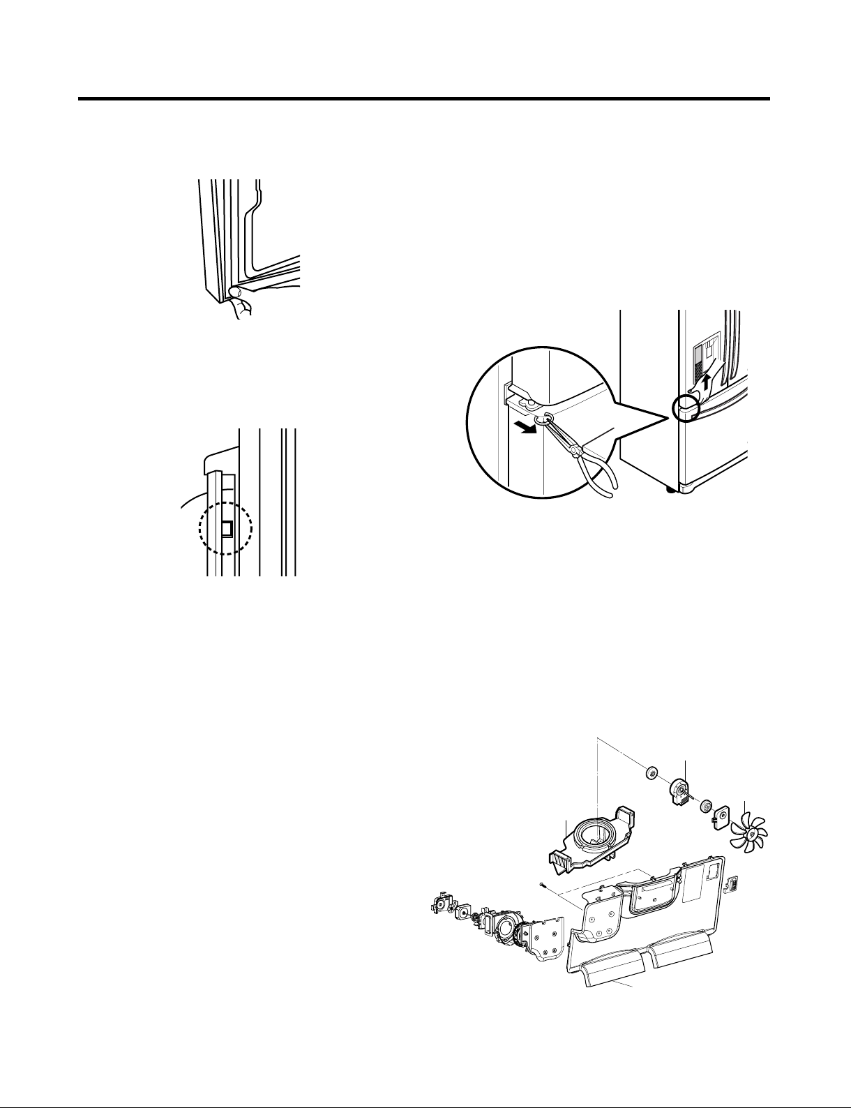
3. Replace door frame cover
Starting at top of cover and working down, snap cover
back into door.
3-4 DOOR ALIGNMENT
If the space between your doors is uneven, follow the
instructions below to align the doors:
1. With one hand, lift up the door you want to raise at
middle hinge.
2. With other hand, use pliers to insert snap ring as shown.
3. Insert additional snap rings until the doors are aligned. 3.
(Three snap rings are provided with unit.)
Figure 8
Figure 7
3-5 FAN AND FAN MOTOR(EVAPORATOR)
1. Remove the freezer shelf. (If your refrigerator has an
icemaker, remove the icemaker first)
2. Remove the plastic guide for slides on left side by
unscrewing phillips head screws.
3. Remove the grille by removing one screw and pulling the
grille forward.
4. Remove the Fan Motor assembly by loosening 2 screws
and disassembling the shroud.
5. Pull out the fan and separate the Fan Motor and Bracket.
FAN MOTOR
BRACKET
MOTOR
FAN
- 7 -
GRILLE
CAUTION
DO NOT ATTEMPT TO REMOVE THE MULLION :
REFRIGERANT LINES!
Figure 9
* Ice Fan Scroll Assembly Replacement
1) Remove the plastic guide for slides on left side by
unscrewing phillips head screws.
2) Pull the grille forward as shown in the second picture.
3) Disconnect wire harness of the grille.
4) Remove the scroll assembly by loosening all screws.
(1) (2)
(3) (4)
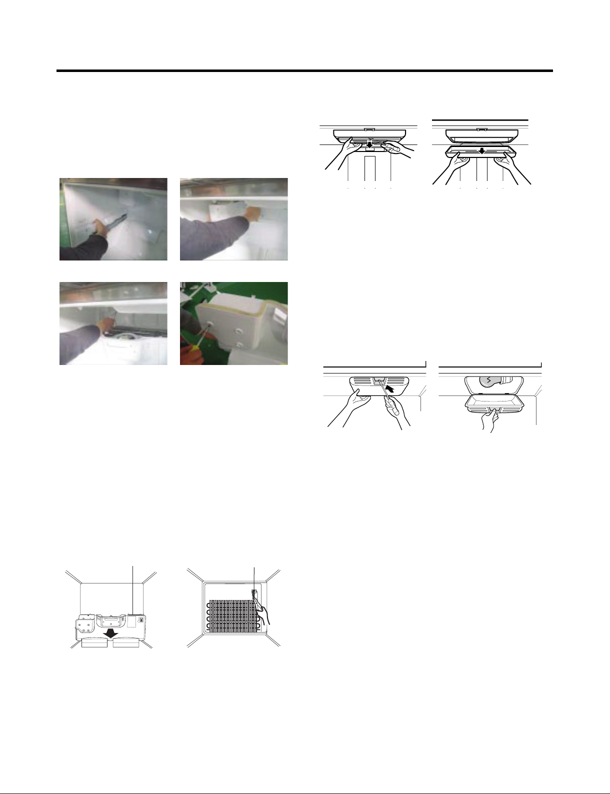
3-7 LAMP
Figure 12
3-7-1 Refrigerator Compartment Lamp
1. Unplug Refrigerator, or disconnect power at the circuit
breaker.
2. If necessary, remove top shelf or shelves.
3. Using a flat instrument, gently pry the cover loose in the
front as shown. (Figure12) Rotate downward to remove
rear tabs.
4. Make sure the bulbs are cool to the touch.
Turn bulbs counterclockwise to remove.
5. Assemble in reverse order by snapping the Lamp Cover
in, engaging the rear tabs followed by the front tabs.
(Max. 60 W-2EA)
3-6 DEFROST CONTROL ASSEMBLY
Defrost Control assembly consists of Defrost Sensor and
FUSE-M.
The Defrost Sensor works to defrost automatically. It is
attached to the metal side of the Evaporator and senses its
temperature. At 46°F (8°C), it turns the Defrost Heater off.
Fuse-M is a safety device for preventing over-heating of the
Heater when defrosting.
1. Pull out the grille assembly. (Figure 10)
2. Separate the connector with the Defrost Control
assembly and replace the Defrost Control assembly after
cutting the Tie Wrap. (Figure 11)
GRILLE ASSEMBLY
Figure 10 Figure 11
DEFROST-CONTROL
ASSEMBLY
Figure 13
3-7-2 Freezer Compartment Lamp
1. Unplug refrigerator power cord form outlet.
2. Pull light bulb cover down to remove.(Figure13)
3. Remove old bulb. Replace with 60-watt appliance bulb.
4. Insert tabs on back of cover into slots in freezer ceiling.
Push cover up to snap front into place.
- 8 -
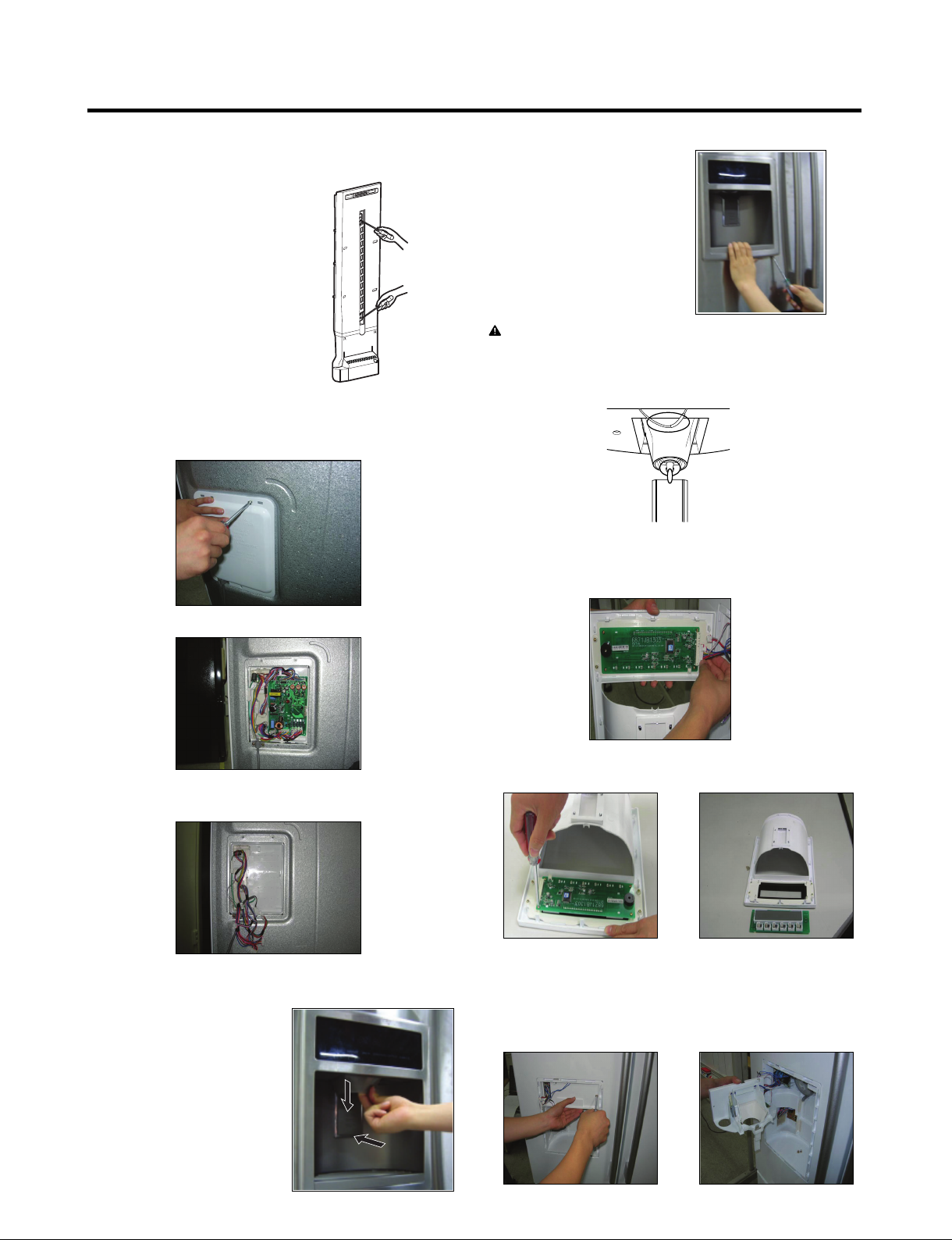
3-8 MULTI DUCT
1. Remove the upper and
lower Caps by using a
flat screwdriver, and
remove 2 screws. (Figure
15)
2. Disconnect the lead wire
on the bottom position.
3-9 MAIN PWB
1) Loosen the 3 screws on the PWB cover.
Figure 15
2) Remove display frame
assembly by making a gap
between a display frame
assembly and door with a
flat blade screwdriver and
pulling it forward. The cover
dispenser is attached with a
hook.
CAUTION: When replacing the dispenser cover in the
reverse order of removal, be careful that the lead wire
does not come out and the water tube is not pinched by
the dispenser cover, as shown in the picture below.
3-11 DISPLAY PWB REPLACEMENT
1) Pull up and out on the dispenser cover to remove.
2) Remove the PWB cover
3) Disconnect wire harness and replace the main PWB in
the reverse order of removal.
3-10 DISPENSER
1) Disconnect funnel and
button assembly by
pulling down and
forward.
2) Follow the steps in the pictures
3-12 FUNNEL REPLACEMENT
1) Pull up and out on the dispenser cover to remove.
2) Disconnect the wire harness.
3) Replace in reverse order.
- 9 -
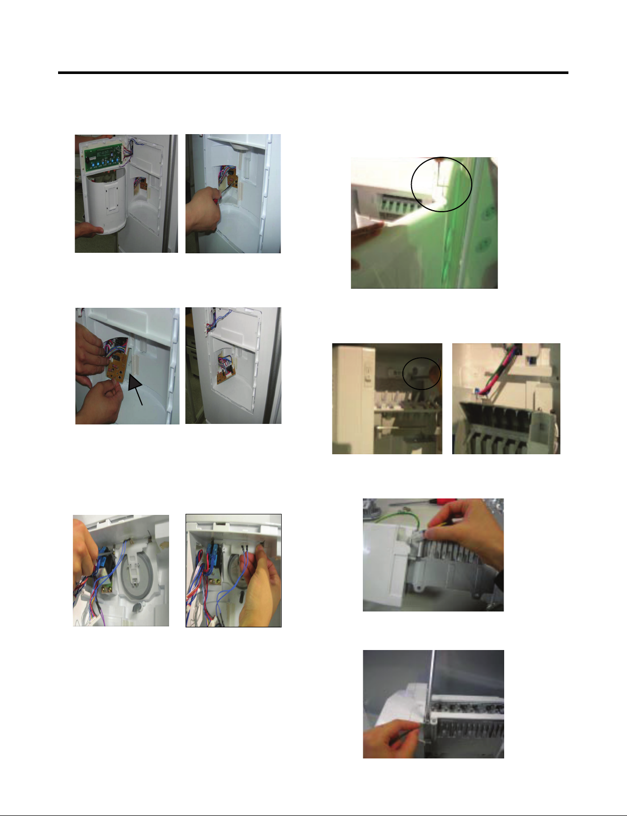
3-13 SUB PWB FOR WORKING DISPENSER
1) Loosen the screw on the sub PWB.
2) Pull the sub PWB down.
3) Disconnect the wire harness and replace the sub PWB in
the reverse order of removal.
3-15 ICE CORNER DOOR REPLACEMENT
1) Loosen the front screw as shown in the picture.
2) Lift up the hinge with one hand.
3) Pull out the Ice Corner Door with the other hand.
hinge
3-16 ICEMAKER ASSEMBLY
1) Loosen two screws as shown in the first picture.
3-14 DUCT DOOR REPLACEMENT
1) Pull up and out on the dispenser cover to remove.
2) Disconnect the wire harness.
3) Remove the funnel
4) Replace in reverse order.
2) Disconnect the wire harness & ground screw replace
theIcemaker assembly in the reverse order of removal.
3) It separates a ground connection screw.
- 10 -- 10 -
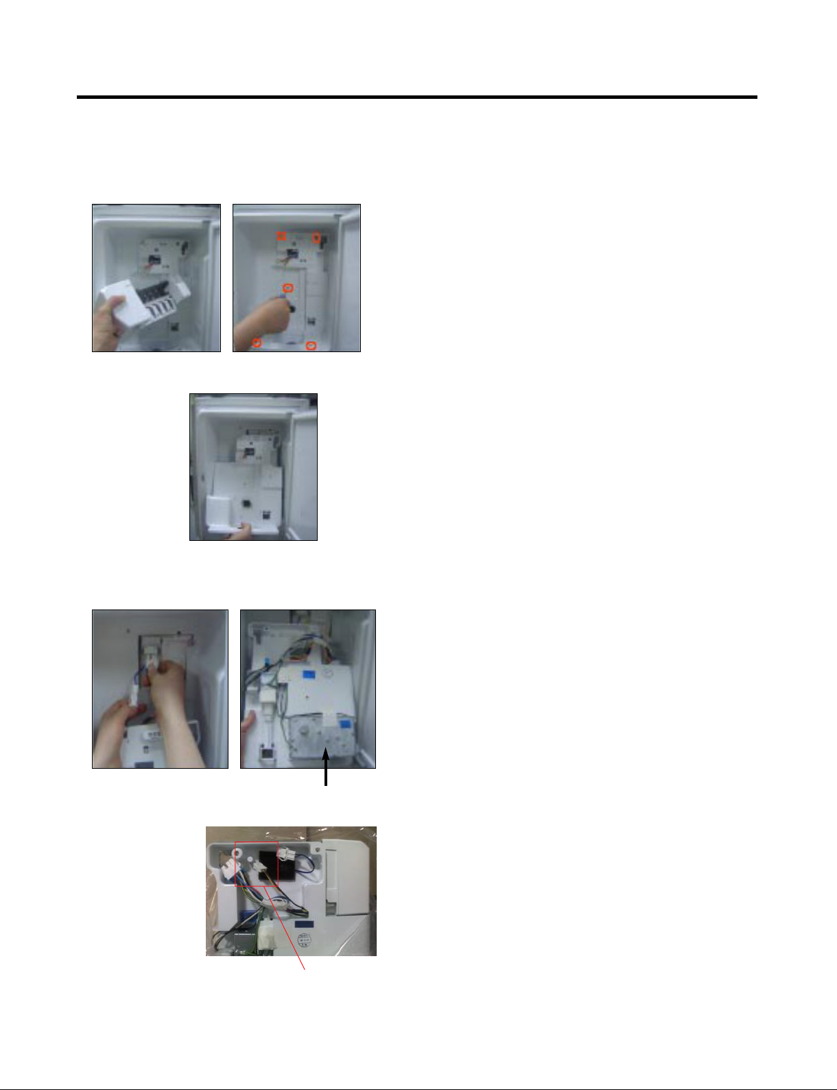
3-16 AUGER MOTOR COVER
1) After removing the icemaker remove the (5) stainless
screws holding the auger motor cover, shown in the
picutres below.
2) Grip the bottom of motor cover assembly and pull out it.
3) Disconnect wire harness of motor cover assembly.
There is a auger motor on the back, as shown in the
picture.
Auger Motor
Icemaker Power &
Full detection Signal
- 11 -
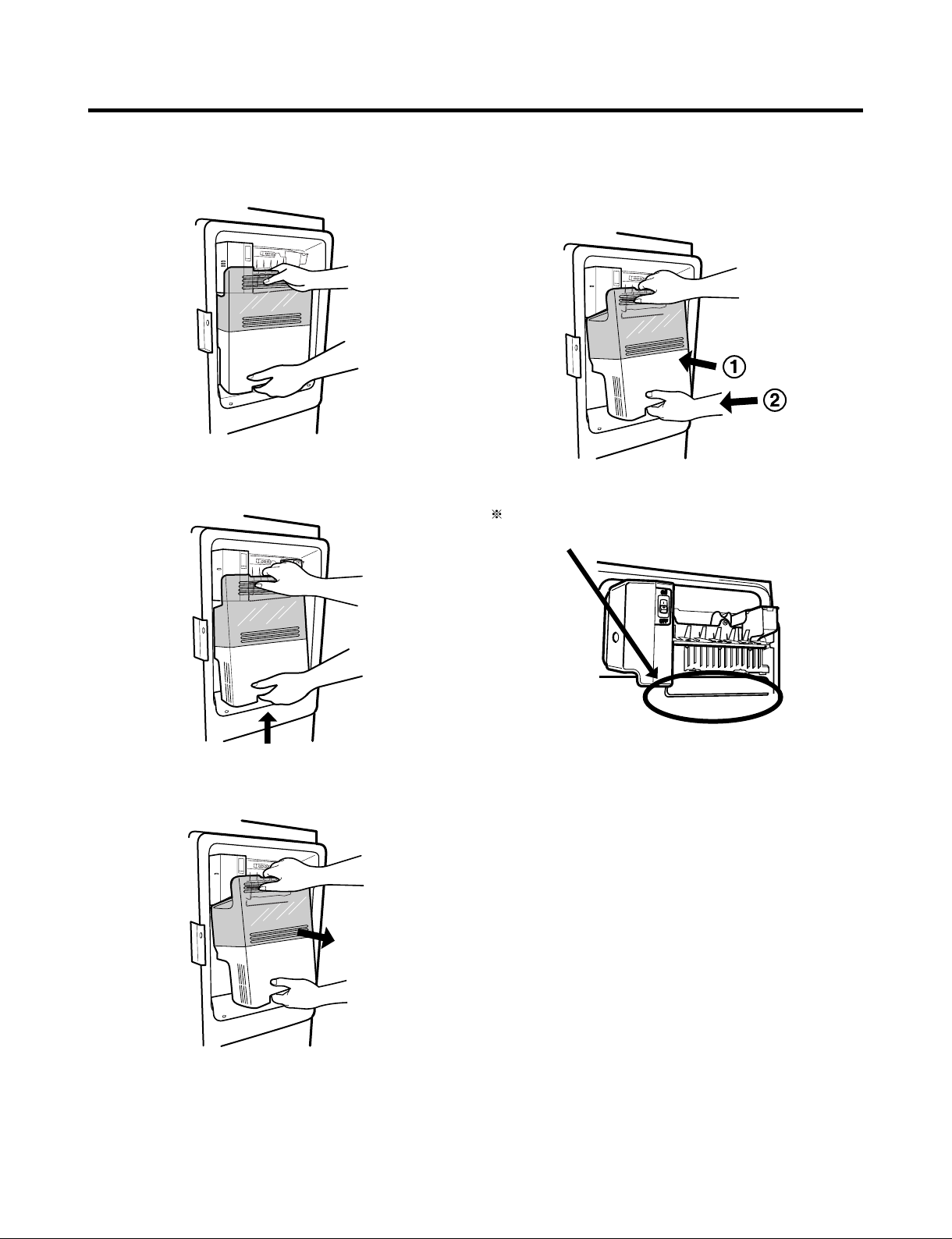
3-17 HOW TO REMOVE A DOOR ICE BIN
1) Grip the handles, as shown in the picture.
2) Lift the lower part slightly.
3-18 HOW TO INSERT A DOOR ICE BIN
1) Insert the Ice Bin, slightly tilting it to avoid touching the
Icemaker. (especially, ice maker lever)
Insert the ice bucket carefully avoid contacting the
automatic shut off arm.
3) Take the Ice Bin out slowly.
- 12 -
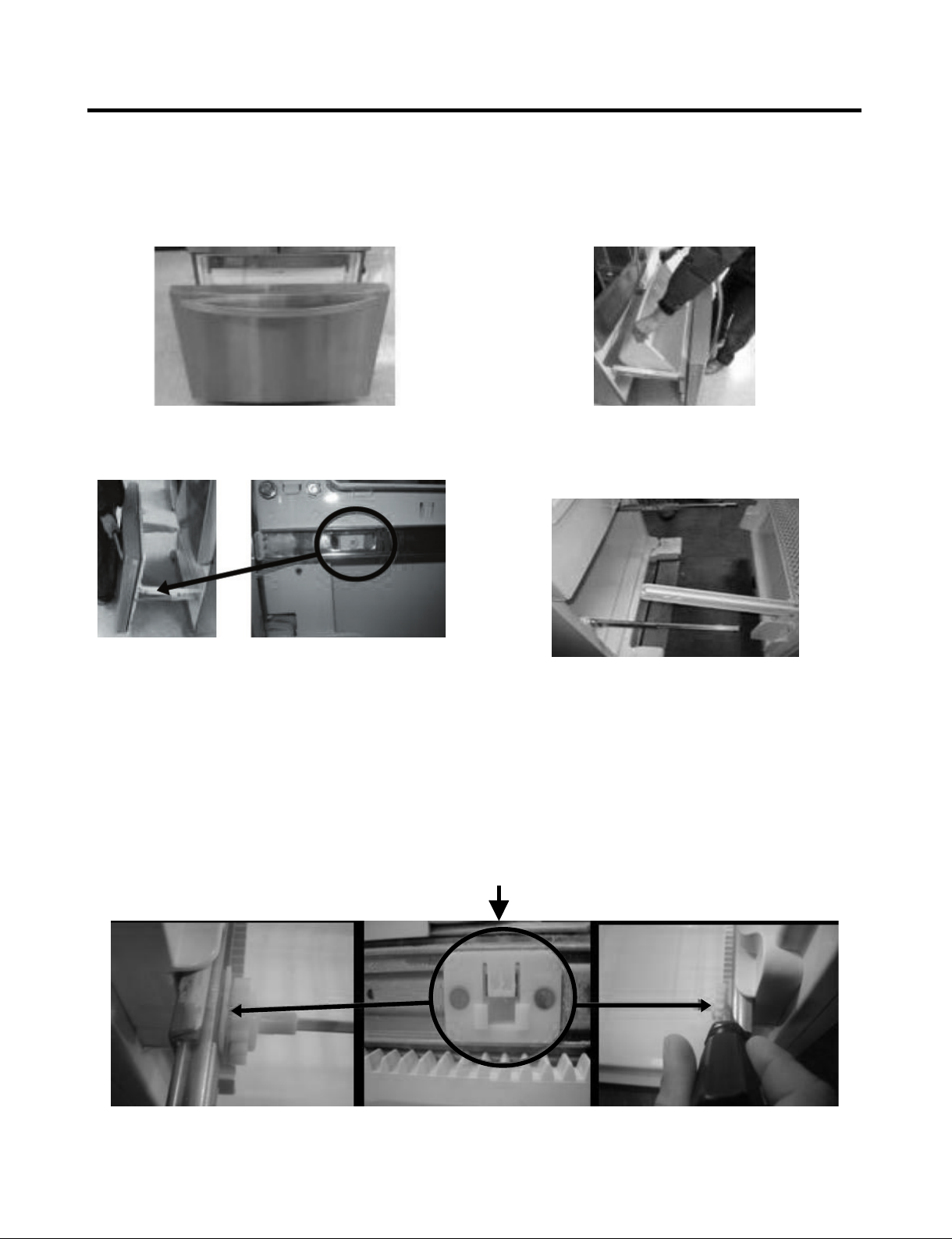
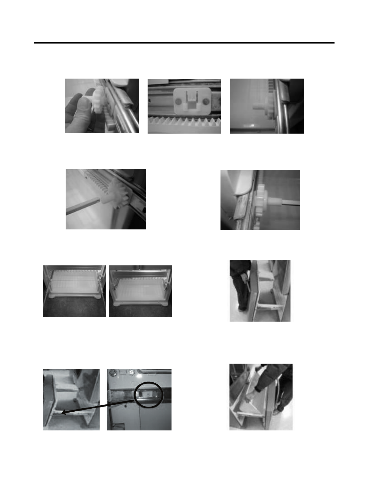
3-19 HOW TO REMOVE AND REINSTALL THE PULLOUT DRAWER
3-19-1 Follow Steps to Remove
Step 1) Open the freezer door. Step 2) Remove the lower basket.
Step 3) Remove the two screws from the guide rails (one
from each side).
Step 5) First: Remove the gear from the left side first by releasing the tab behind the gear, place a screwdriver between the
gear and the tab and pull up on the gear.
Second: Remove the center rail.
Third: Remove the gear from the right side by following the same steps for the left side.
Step 4) Lift the freezer door up to unhook it from the rail
support and remove.
Pull both rails to full extension.
NOTE: THIS TAB MUST BE PUSHED IN TO RELEASE THE GEAR.
- 13 -
3-19-2 Follow Steps to Reinstall
Step 1) Reinstall the right side gear into the clip.
Step 2) Insert the rail into the right side gear. Gears do not
need to be perpendicular to each other.
Step 4) The rail system will align itself by pushing the rails
all the way into the freezer section.
Pull the rails back out to full extension.
Step 3) Insert the rail into the left side gear, and insert the
gear into the clip.
Step 5) Reinstall the freezer door by inserting the rail tabs
into the guide rail.
Step 6) Reinstall the two screws into the guide rails
(one from each side).
Step 7) Reinstall the lower basket, and close the freezer
door.
- 14 -
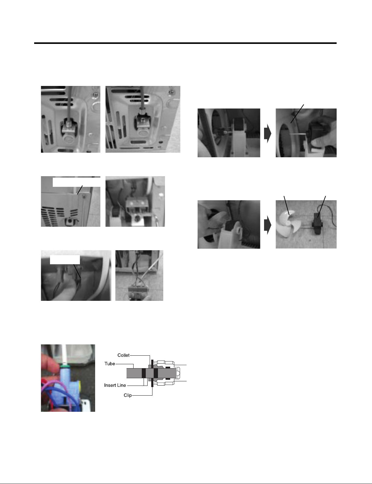
3-20 WATER VALVE DISASSEMBLY METHOD
1) Turn off the water. Then separate the water line from the
valve.
3-21 FAN AND FAN MOTOR DISASSEMBLY
METHOD
1) Using a short screwdriver, loosen one SCREW in DRAIN
PIPE ASSEMBLY and one connected to the MOTOR
COVER.
MOTOR COVER
2) Separate the Mechanical Cover and Valve Screw.
Mechanical Cover
3) Separate the housing and pull out the valve.
Housing
4) Lay a dry towel on the floor and get ready to spill water
from the water filter. Pull out the Cilp. Then press te
collet to separate the tube from the connector and pour
out the water until emptied.
2) Pull and separate the FAN ASSEMBLY and MOTOR
turning counterclockwise based on the MOTOR SHAFT.
FAN ASSEMBLY MOTOR
The assembly is in the reverse order of the disassembly
and take special care for the following details.
1. Be careful not to bend the tube during assembly.
2. Press the WATER DISPENSER button until water pours
out and check for leakage in the CONNECTOR TUBE
(It differs by the water pressure but usually takes about 2
minutes until water pours out.)
- 15 -
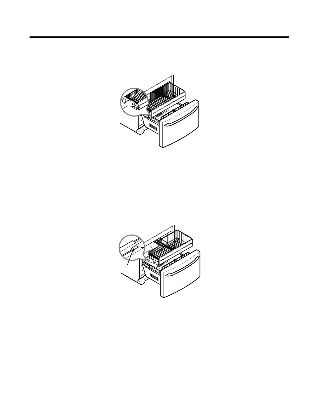
3-22 PULL OUT DRAWER
To remove the drawer, push the tabs located on the front inside surface of each rail. Next, gently lift the rear left and right
sides of the drawer and pull it out.
To reinstall, pull out both rails to full extension. Insert the end of rib in the bracket at left and right. Making sure that the
guides at the front are lined up properly, gently push down on both sides.
Bracket
- 16 -
 Loading...