

LG LFX21960ST, LFX25960xx Training Manual

LG TRAINING MANUAL
LG TRAINING MANUAL
French Door Refrigerator - Fall 2007
Models:
LFX21960ST
LFX25960xx

REFRIGERATOR
Customer Service (and Part Sales) (800) 243-0000
Technical Support (and Part Sales) (800) 243-0000
USA Website us.lgservice.com
Customer Service Website us.lgservice.com
B2B Service Website biz.lgservice.com
LG CS Academy lgcsacademy.com
This manual was current at the time of publication; however, all information contained herein is subject to
change. When ordering parts, always order by model number and serial number. If the part has been changed,
the newer part will be provided.
Published by LG Technical Support
Service
LFX21960ST/LFX25960xx Page 2 of 75 TRAINING MANUAL

REFRIGERATOR SAFETY
IMPORTANT SAFETY NOTICE
The information in this training manual is intended for use by persons possessing an adequate background
in electrical equipment, electronic devices, and mechanical systems. In any attempt to repair a major
appliance, personal injury and property damage can result. The manufacturer or seller maintains no liability
for the interpretation of this information, nor can it assume any liability in conjunction with its use. When
servicing this product, under no circumstances should the original design be modified or altered without
permission from LG Electronics. Unauthorized modifications will not only void the warranty, but may lead to
property damage or user injury. If wires, screws, clips, straps, nuts, or washers used to complete a ground
path are removed for service, they must be returned to their original positions and properly fastened.
Always unplug the product before servicing. Do not touch metal parts in the freezer with wet hands. Unload
the refrigerator before moving it. Servicers should be CFC certified.
CAUTION
To avoid personal injury, disconnect the power before servicing this product. If electrical power is required
for diagnosis or test purposes, disconnect the power immediately after performing the necessary checks.
Also be aware that many household appliances present a weight hazard. At least tw o people should be
involved in the installation or servicing of such devices. Failure to consider the weight of an appliance could
result in physical injury. Wear protective gloves when handling the evaporator coil to prevent cuts.
REFRIGERANT
Use eye protective wear when soldering or brazing. Remember that refrigerant escaping will freeze the
surface of the eye, causing irreparable blindness. Servicers working on the sealed system must be properly
trained and certified to handle refrigerants. Use of the proper tools is critical to proper repairs. Refrigerant
must be recovered using an approved recovery device.
ESD NOTICE
Some of the electronic in appliances are electrostatic discharge (ESD) sensitive. ESD can weaken or
damage the electronics in these appliances in a manner that renders them inoperative or reduces the time
until their next failure. Connect an ESD wrist strap to a ground connection point or unpainted metal in the
appliance. Alternatively, you can touch your finger repeatedly to a ground connection point or unpainted
metal in the appliance. Before removing a replacement part from its package, touch the anti-static bag to a
ground connection point or unpainted metal in the appliance. Handle the electronic control assembly by its
edges only. When repackaging a failed electronic control assembly in an anti-static bag, observe these
same precautions.
REGULATORY INFORMATION
This equipment has been tested and found to comply with the limits for a Class B digital device, pursuant to
Part 15 if the FCC Rules. These limits are designed to provide reasonable protection against harmful
interference when the equipment is operated in a residential installation. This equipment generates, uses,
and can radiate radio frequency energy, and, if not installed and used in accordance with the instruction
manual, may cause harmful interference to radio communications. However, there is no guarantee that
interference will not occur in a particular installation. If this equipment does cause harmful interference to
radio or television reception, which can be determined by turning the equipment off and on, the user is
encouraged to try to correct the interference by one or more of the following measures: Reorient or relocate
the receiving antenna; Increase the separation between the equipment and the receiver; Connect the
equipment to an outlet on a different circuit than that to which the receiver is connected; or consult the
dealer or an experienced radio/TV technician for help.
COMPLIANCE
The responsible party for this device’s compliance is LG Electronics Alabama, Inc.; 201 James Record Road,
Huntsville, AL 35813.
LFX21960ST/LFX25960xx Page 3 of 75 TRAINING MANUAL

REFRIGERATOR CONTENTS
CONTENTS
SAFETY, CAUTIONS, and WARNINGS 3
CONTENTS 4
INTRODUCTION 7
Specifications 8
Features 9
Warranty 10
INSTALLATION 11
Unpacking 12
Installation
Evening the Doors 13
Base Grille (Kick Plate) 14
Door Handles 14
Door Removal 14
Water Line Connection 15
OPERATION 16
Controls 16
Ice Plus 16
Dispenser Lock 16
Filter Reset 16
DISASSEMBLY 17
Refrigerator Door Removal 17
Freezer Door Removal 18
Freezer Door Replacement 19
Door Frame Removal 20
Door Gasket Clip Release 20
Door Gasket Replacement 22
Door Gasket Clip Replacement 22
Door Frame Replacement 23
Dispenser 24
Filter 24
Freezer Fan and Motor 25
Ice Room Fan 25
Defrost Control Assembly 26
Refrigerator Lamp 26
Freezer Lamp 27
LFX21960ST/LFX25960xx Page 4 of 75 TRAINING MANUAL

REFRIGERATOR CONTENTS
CONTENTS, continued
ICEMAKER 28
Theory of Operation 28
Icemaker Functions (modes) 29
Function Test 30
Error Codes 30
COMPRESSOR 31
PTC Starter (Positive Temperature Coefficient) 32
OLP (Overload Protector) 33
TROUBLESHOOTING 35
Compressor and Electrical Components 37
PTC and OLP 38
Other Electrical Components 39
Service Diagnosis Chart 40
Refrigeration Cycle 41
Sealed System 42
LED Test 43
Test Mode 43
ERROR CODES (Defect Diagnosis) 44
MICOM CIRCUITS AND FUNCTIONS 45
Display Defaults (OF or OC, Lock, Filter) 45
Ice Plus 46
Lamp Auto Off 46
Door Open Alarm 47
Buzzer 47
Defrost Mode 47
Initialization Sequence 48
Demo Mode 48
LFX21960ST/LFX25960xx Page 5 of 75 TRAINING MANUAL

REFRIGERATOR CONTENTS
CONTENTS, continued
PCB CIRCUITS 49
Power Circuit 49
Oscillator Circuit 50
Reset Circuit 50
Load Drive Circuit 51
Freezer Fan Motor Drive Circuit 51
Door Open Detection Circuit 52
Temperature Sensor Circuit 52
Refrigerator Damper Circuit 53
Dispenser Input Circuit 53
Temperature Compensation Circuit 53
Temperature Compensation Table 54
Freezer Sensor Resistance Specification 54
Display Light and Button Circuit 55
SCHEMATICS 56
Circuit Diagram 56
Main Board Layout 57
Main Board Parts List
Display Board Schematic 59
Display Board Parts Layout 60
Display Board Parts List 60
EXPLODED VIEWS 61
Case Parts 61
Freezer Parts 62
Refrigerator Parts 63
Door Parts 64
Ice and Water Parts 65
Icemaker Parts 66
Dispenser Parts 67
PARTS LIST 68
NOTES 75
APPENDICES 78
58
LFX21960ST/LFX25960xx Page 6 of 75 TRAINING MANUAL

REFRIGERATOR INTRODUCTION
INTRODUCTION
The French Door (three-door) Refrigerator is basically similar to a regular door
refrigerator. The refrigeration portion, the freezer, the shelves, and the controls
are the same; the difference is that the French Door model has 2 narrow doors
hinged on either side of the refrigerator and opening independently from the
center. The doors are not interchangeable or reversible, but they can be removed
if necessary for moving the refrigerator through doorways. Some models include
a water dispenser in the left door and/or a tilt-out freezer door. The freezer door
is easily removed.
This training manual covers installation, operation, testing, diagnosis, and repair.
There is a special section for Tips & Tricks to make the job easier. Full
schematics and parts lists are included.
Drawings and photos are used for explanation. Additionally, many of these topics
are covered in video training available via Internet at LG CS Academy.
(http://www.lgcsacademy.com)
LFX21960ST/LFX25960xx Page 7 of 75 TRAINING MANUAL
REFRIGERATOR SPECIFICATIONS
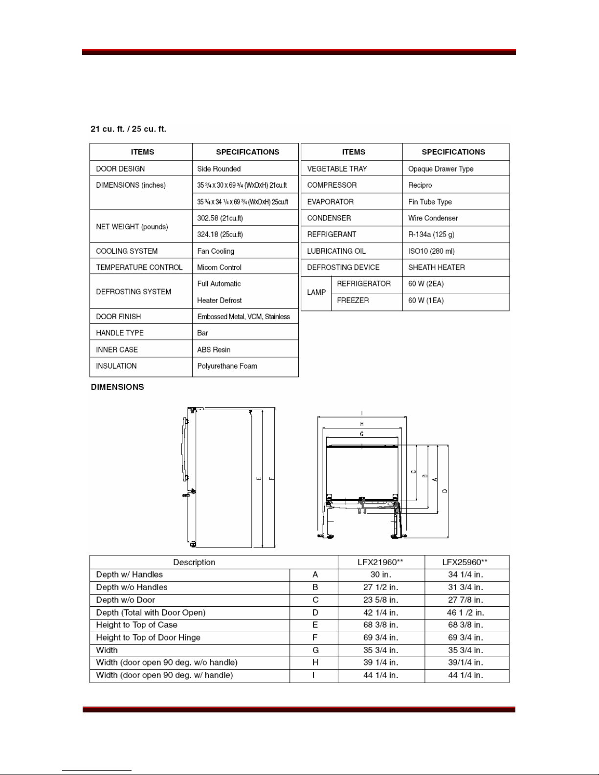
SPECIFICATIONS
LFX21960ST/LFX25960xx Page 8 of 75 TRAINING MANUAL
REFRIGERATOR SPECIFICATIONS
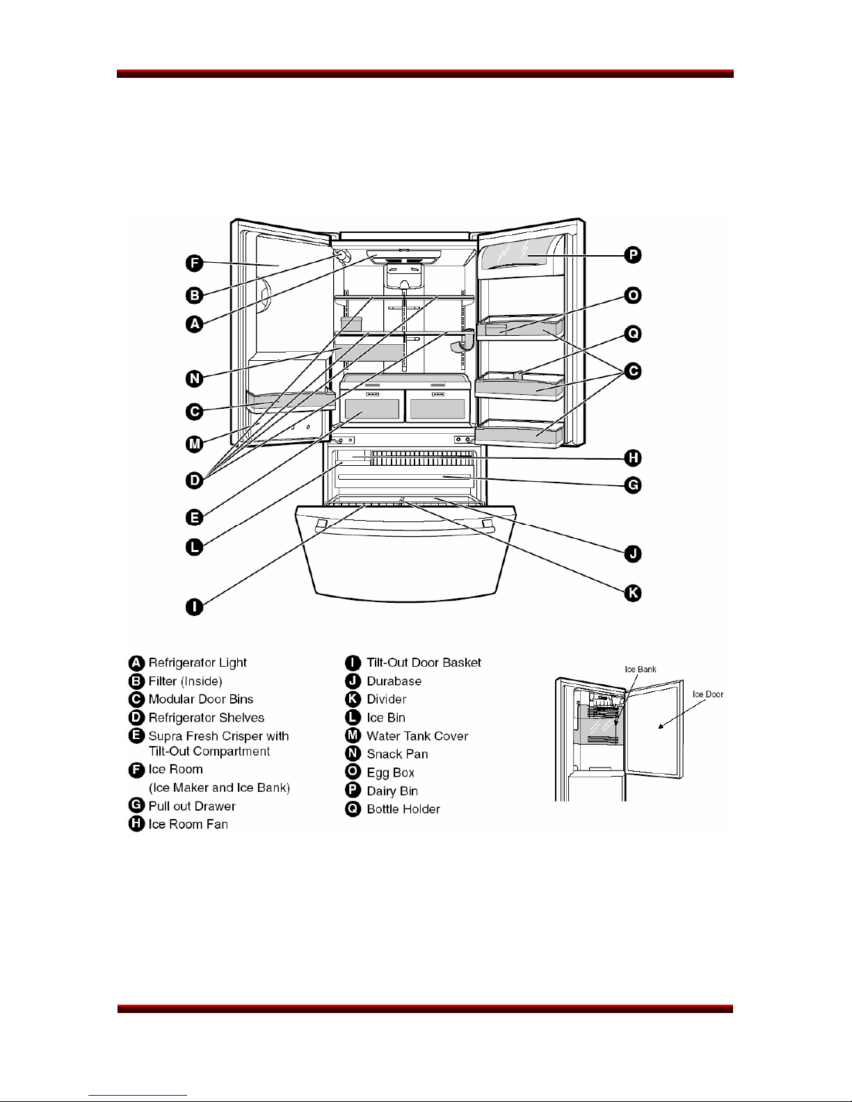
FEATURES
LFX21960ST/LFX25960xx Page 9 of 75 TRAINING MANUAL
REFRIGERATOR WARRANTY
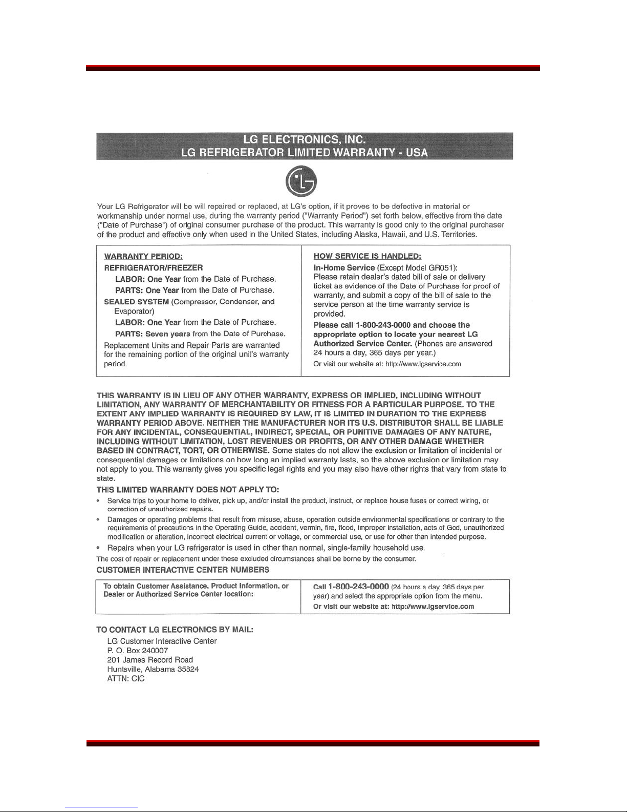
WARRANTY
(May vary by model)
LFX21960ST/LFX25960xx Page 10 of 75 TRAINING MANUAL

REFRIGERATOR INSTALLATION
INSTALLATION
Installation is relatively straight-forward.
• Use at least two people to move and install this refrigerator.
• Do not lay the refrigerator on its side to store or transport it.
• Leave the refrigerator in the factory packaging until it is delivered to the
place of installation.
• Unbox and unpack the refrigerator. Make sure no small parts or
accessories are thrown away in the packing.
• Make sure the leveling legs are in the highest position before moving.
(See page 13.)
• Do not roll the refrigerator across pavement, gravel, or rough surfaces.
The wheels will be damaged and will, in turn, damage the customer’s floor.
• Roll the refrigerator to the installation area. If you have to remove the
doors, there is a section in the manual covering that. (See pages 20-21.)
Be cautious to avoid damaging the refrigerator or the flooring!
• Connect the water line, if applicable. Turn on the water and check for
leaks. There is a section in this manual covering that. (See page 15.)
• Roll the refrigerator into place.
• Level the refrigerator by lowering the leveling legs and taking the weight
off the front rollers. The doors can be evened using this same procedure.
(See page 13.)
• Install the lower cover (kick plate or base grille). (See page 14.)
• Plug in the refrigerator.
• Install all the shelves, door bins, and accessories in the desired places.
Set the desired temperature.
• Allow 24 hours for the refrigerator to cool down, stabilize its temperature,
and begin making ice.
LFX21960ST/LFX25960xx Page 11 of 75 TRAINING MANUAL

REFRIGERATOR INSTALLATION
UNPACKING
Leave the refrigerator in its box and packaging until it is at the installation area.
Remove the box and any shipping tape and temporary labels. DO NOT
REMOVE the serial number label or any WARNING labels.
After cutting the straps, lift the box off over the top of the refrigerator. This is
usually easier outdoors, where there is sufficient vertical clearance.
To remove any tape residue, rub it with your finger. If that doesn’t roll it up, rub it
with a couple of drops of dishwashing liquid and wipe it off with a damp towel.
DO NOT USE sharp instruments, rubbing alcohol, flammable liquids, solvents, or
abrasive cleaners.
The shelves are installed in the shipping position at the factory. After removing all
the cardboard and shipping materials, the customer can arrange the shelves
according to his personal preference.
INSTALLATION
While most kitchens have a place already designed for a refrigerator, we remind
you not to install the refrigerator near a heat source, a damp spot, or in bright
sunlight. The refrigerator is designed to be installed in an area where the ambient
temperature is between 55° F and 110° F (13° C and 43° C). If the ambient
temperature is outside this specification, the refrigerator’s performance may be
affected adversely.
Connect the water line. (See page 15.) Turn on the water and check for leaks
before pushing the refrigerator into position.
To avoid vibration, the refrigerator must be level. After rolling the refrigerator into
position, lower the leveling legs to take the weight off the front wheels and level
the refrigerator.
Turn the feet with a screwdriver to raise
or lower the front of the refrigerator.
The large hole visible is for the type of
base grille that presses into place
instead of being attached with screws.
The feet are also used to align the
doors so they hang evenly.
(See next page.)
LFX21960ST/LFX25960xx Page 12 of 75 TRAINING MANUAL
REFRIGERATOR INSTALLATION
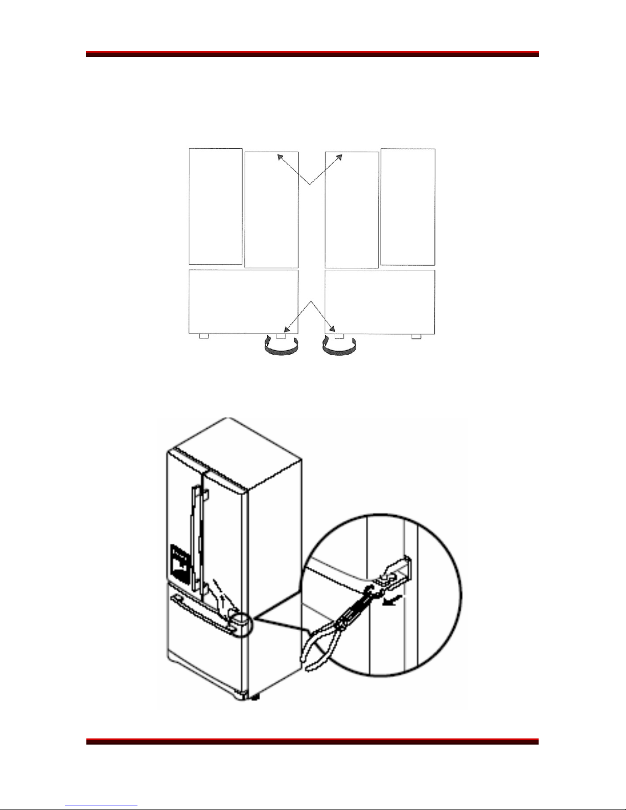
EVENING THE DOORS
Use the leveling feet to make the doors hang evenly. If one side of the
refrigerator is lower, the doors will hang crookedly.
Turn the leg under the lower door clockwise to raise that side. If there is not
sufficient adjustment, it may be necessary to use up to three snap rings as shims
on the lower hinge pin. Three snap rings are provided with the refrigerator.
LFX21960ST/LFX25960xx Page 13 of 75 TRAINING MANUAL
REFRIGERATOR INSTALLATION
BASE GRILLE (Kick Plate)
Install the base grille (kick plate). Open
the freezer door, put the grille into
place, and attach it with the screws
provided. Some models may have a
grille that is pressed into place and
held by two plastic pegs.
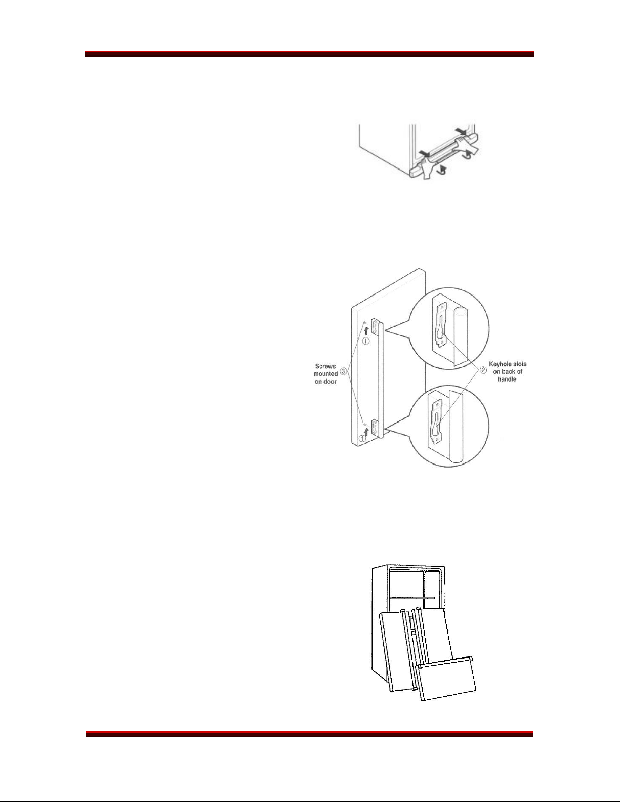
DOOR HANDLES
The door handles are attached by a
bracket at each end of the handle.
The bracket has a keyhole slot on
the back to fit over the bolts in the
door and slide into place.
Slide the door handle UP to remove it,
DOWN to replace it.
The freezer door handle works in a
similar manner. Slide it RIGHT to
remove it, LEFT to replace it. If it is
necessary to remove the doors to get
the refrigerator into the house, see the
DOOR REMOVAL section on pages
20-21.
DOOR REMOVAL
Child entrapment and suffocation are
not things of the past. Junked or
abandoned refrigerators are
dangerous. If you must scrap a
refrigerator, recover the refrigerant and
permanently remove the doors. Leave
the shelves in place so children cannot
crawl in to play. Dispose of the
scrapped product by an
environmentally acceptable method.
LFX21960ST/LFX25960xx Page 14 of 75 TRAINING MANUAL

REFRIGERATOR INSTALLATION
WATER LINE CONNECTION
Before connecting the water to the refrigerator, be sure the water is turned off
and the refrigerator is unplugged.
Connect the water line to the
water valve on the back of the
refrigerator. The connection is a
standard 1/4 inch fitting that will
accept either a compression fitting
or one of the many braided,
reinforced hoses available for this
purpose at most hardware stores.
LFX21960ST/LFX25960xx Page 15 of 75 TRAINING MANUAL

OPERATION
REFRIGERATOR
OPERATION
CONTROLS
The temperature in the freezer and the refrigerator can be set independently of
one another. LG recommends setting the refrigerator at 37° F (3° C) and the
freezer at 0° F (-18° C). Leave the refrigerator at this setting for 24 hours to allow
the temperature to stabilize, then adjust the temperature as desired.
The refrigerator temperature can be set between 32° F (0° C) and 47° F (8° C).
The freezer temperature can be set between -6° F (-21° C) and 8° F (-13° C).
ICE PLUS
Pressing the ICE PLUS button activates that feature and turns on the LED for 24
hours. During that time, the cooling speed of the freezer and ice production will
be intensified.
DISPENSER LOCK
PRESS and HOLD the LOCK button for 3 seconds to lock or unlock the
dispenser. When locked, the dispenser will not operate and the display will be off.
The dispenser will not operate if any door is open.
FILTER RESET
When the FILTER RESET LED lights, it is time to change the water filter. PRESS
and HOLD the FILTER RESET button to turn the LED off. The filter should be
changed every six months, and more often if necessary.
LFX21960ST/LFX25960xx Page 16 of 75 TRAINING MANUAL
REFRIGERATOR DISASSEMBLY
DISASSEMBLY
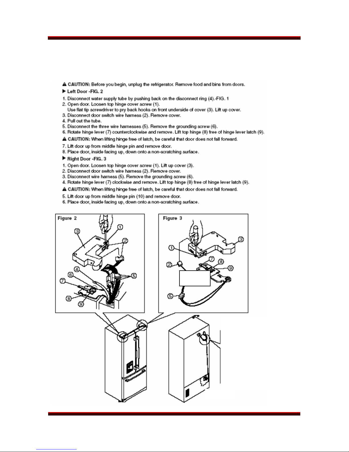
REFRIGERATOR DOOR REMOVAL
Figure 1
LFX21960ST/LFX25960xx Page 17 of 78 TRAINING MANUAL
REFRIGERATOR DISASSEMBLY
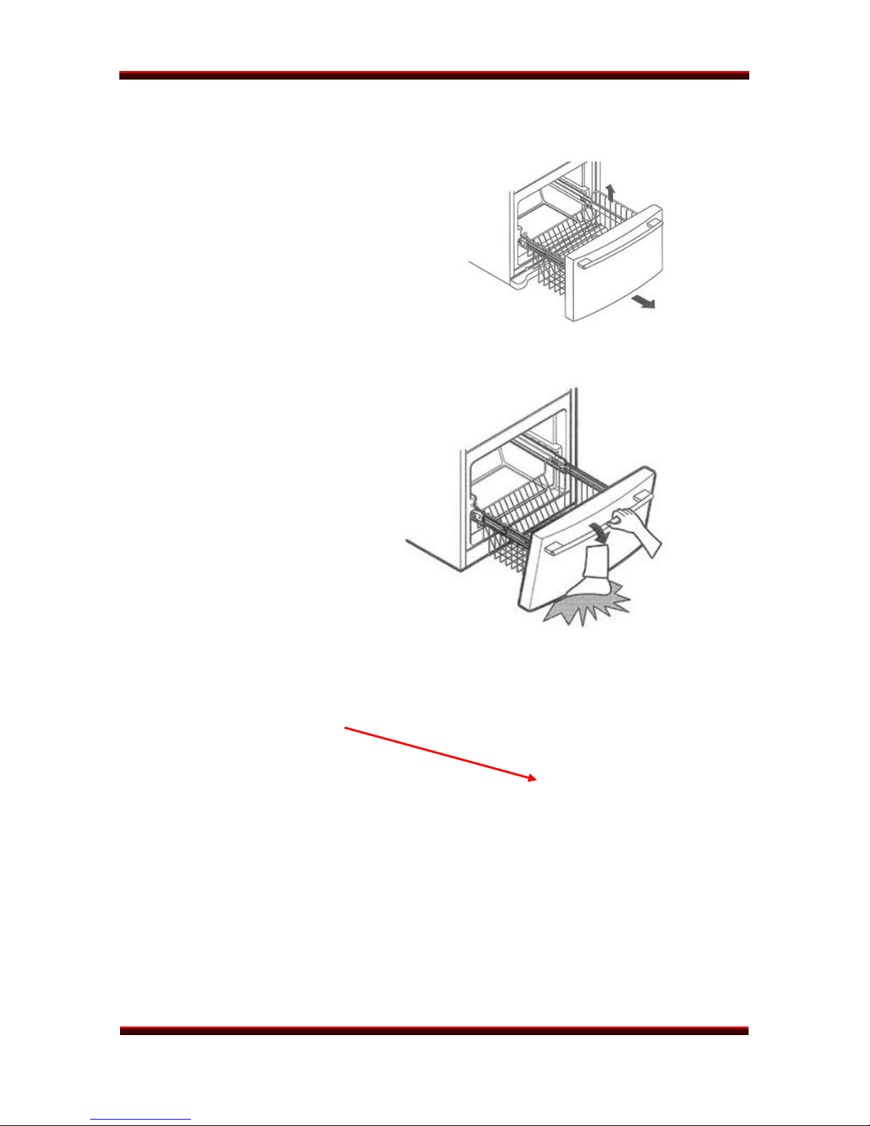
FREEZER DOOR REMOVAL
The freezer door is simple to
remove and replace.
Pull the drawer all the way out.
Lift the basket out.
Remove the screw from both
rails.
Lift the top of the door to unhook
the door supports from the rail.
Then lift the door to remove it.
DO NOT HOLD the door by the
handle. Be careful when setting
the drawer down to avoid injury
to floor or feet.
Alternate method – The freezer
door can be removed by tilting it
out and then raising the clips as
shown (one clip on each side).
LFX21960ST/LFX25960xx Page 18 of 75 TRAINING MANUAL

REFRIGERATOR DISASSEMBLY
FREEZER DOOR REPLACEMENT
Pull the rails all the way out.
Hook the door on the rail tabs, lower the door into place, and tighten the
screw.
Put the basket in and pull it all the way toward the door.
CAUTION!
Be careful removing the doors. They are heavier than you might expect, and
dropping them could damage the doors or cause personal injury.
To prevent accidental child or pet entrapment or suffocation, DO NOT allow them
to play inside the freezer drawer.
DO NOT sit or stand on the freezer door. It may tip over and cause severe injury
or damage.
LFX21960ST/LFX25960xx Page 19 of 75 TRAINING MANUAL
REFRIGERATOR DISASSEMBLY
DOOR FRAME COVER REMOVAL
LFX21960ST/LFX25960xx Page 20 of 75 TRAINING MANUAL
REFRIGERATOR DISASSEMBLY
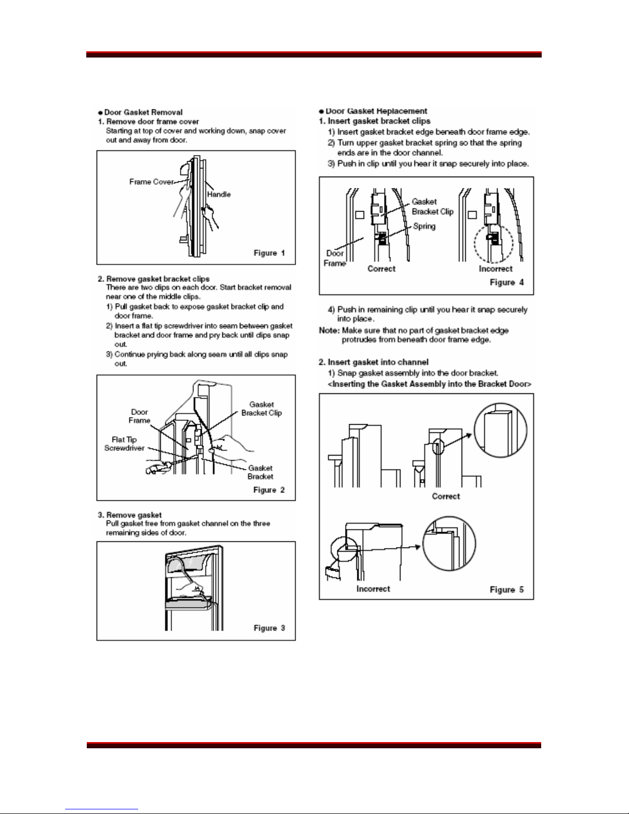
Removal of gasket clips. The other door is just the opposite. The tabs fit into a
rectangular recess in the door and are held by a retaining clip on each side.
Press the clip inward with a small screwdriver, as shown in the photo, to release
the clips. They can be re-installed in the same manner.
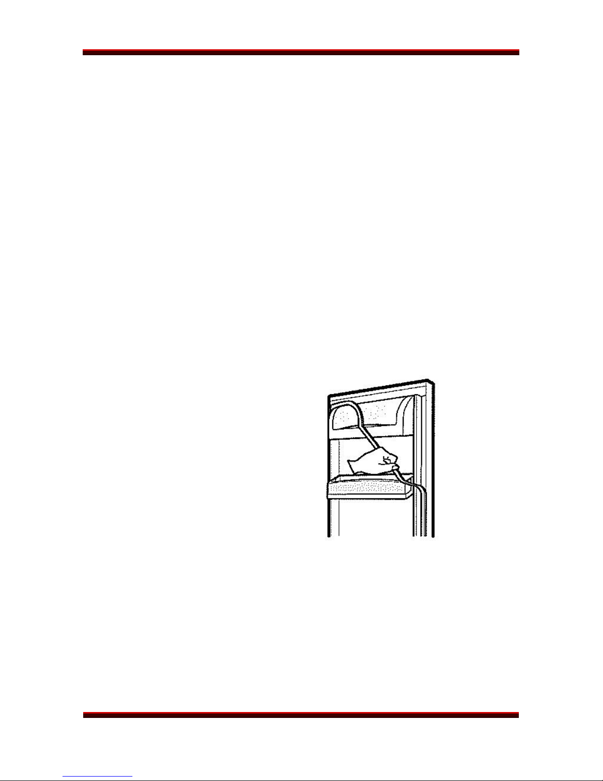
Removing the gasket is easy after the clips are released.
Start at the top corner on the side
where the door edges meet. Pull the
gasket out of the channel from top to
bottom, holding the top to keep it from
falling. Continue across the bottom, up
the side, and back across the top of the
door until the gasket is free.
LFX21960ST/LFX25960xx Page 21 of 75 TRAINING MANUAL
REFRIGERATOR DISASSEMBLY
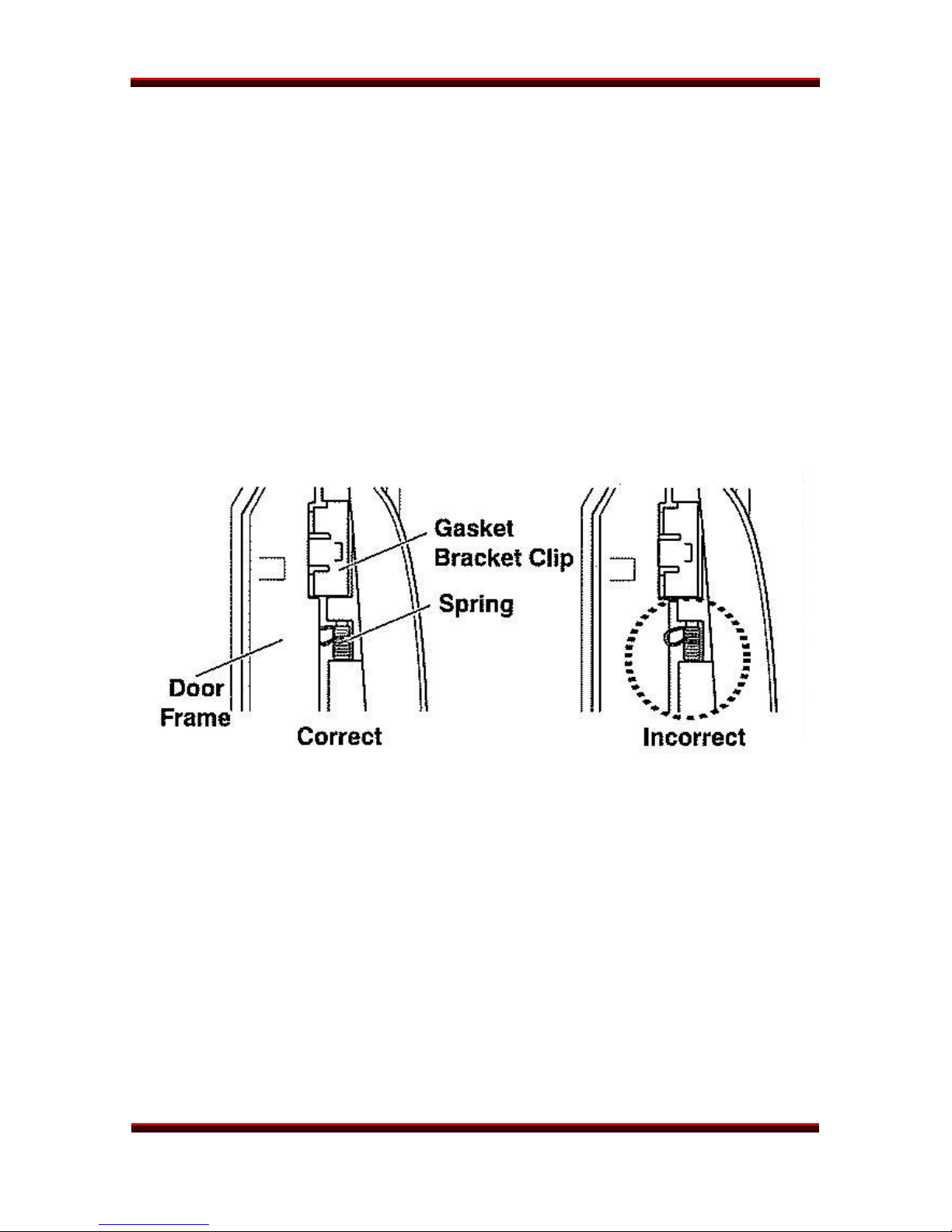
DOOR GASKET REPLACEMENT
1. Insert the gasket bracket edge under the door frame edge.
2. Position the upper gasket bracket spring so both ends are in the door
channel. (See drawing, below.)
3. Push the clip in until you feel it snap firmly into place.
4. Replace the remaining clips the same way.
Make certain no part of the bracket protrudes at the frame edge.
DOOR GASKET BRACKET AND CLIP PLACEMENT
5. Insert the gasket into the channel and slide it all the way down the bracket.
(This is easier when you start it from the top and work toward the bottom.)
LFX21960ST/LFX25960xx Page 22 of 75 TRAINING MANUAL

REFRIGERATOR DISASSEMBLY
6. Press the remaining three sides of the gasket into the groove.
DOOR FRAME COVER REPLACEMENT
Press the door
frame cover into
place, starting at the
top and working
down. Be careful to
avoid breaking the
plastic tabs.
LFX21960ST/LFX25960xx Page 23 of 75 TRAINING MANUAL
REFRIGERATOR DISASSEMBLY
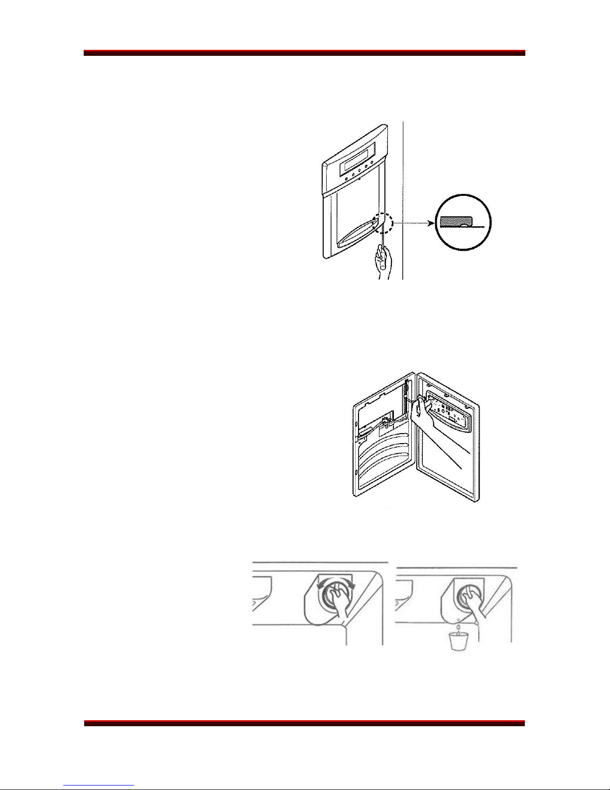
DISPENSER
1. Use a flat tip screwdriver to pry
the dispenser cover away from
the face of the door. Pry out at
the bottom; the dispenser folds
out at the top.
2. Pry gently to disengage the
plastic hooks without breaking
them off.
HINT: Put a small piece of tape
below the dispenser to avoid
scratching the finish.
3. Separate the connector before
pulling the dispenser away.
4. Replacement is the reverse of
these steps.
FILTER
Twist the filter
counterclockwise to remove
it. Insert the new filter and
twist it clockwise until it
clicks into place.
Put a cup under the hole at
the rear of the filter holder
to catch the drip when the
filter is removed.
LFX21960ST/LFX25960xx Page 24 of 75 TRAINING MANUAL
REFRIGERATOR DISASSEMBLY
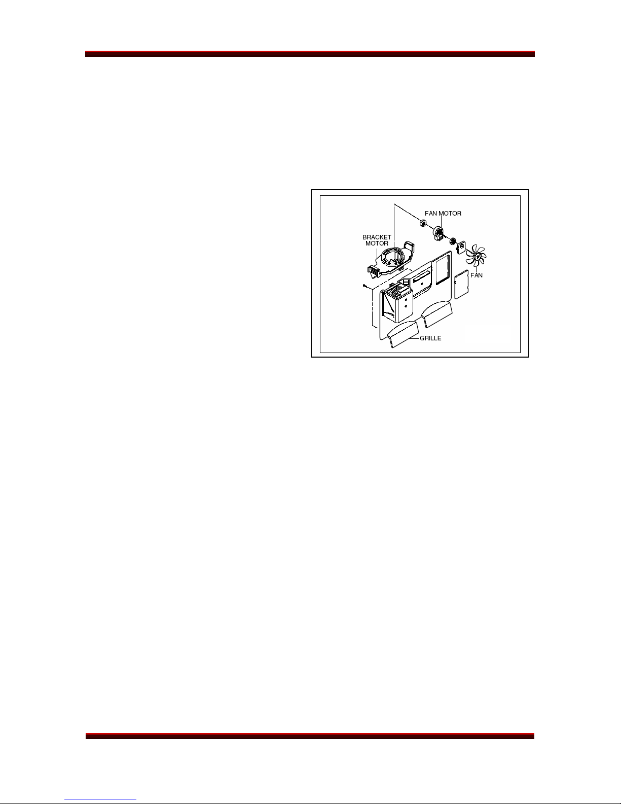
FREEZER FAN AND MOTOR
1. Open the freezer. It may be
easier to work on the freezer
fan and motor if you remove
the freezer door first.
(See page 21.)
2. Remove the icemaker.
3 Remove the screws that hold
the plastic guide on the left
side of the freezer.
4. Remove the screw in the
access panel of the grille.
5. Remove two screws to take off
the fan bracket and motor as an
assembly.
6. Pull the fan blade off the shaft
and remove the motor from the
bracket.
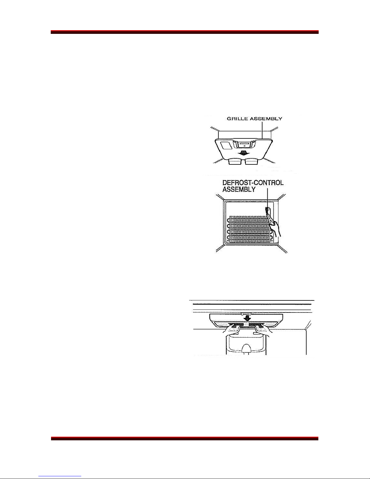
ICE ROOM FAN
1. Remove the grille (steps 1–4 above).
2. Disconnect the wire harness from the grille.
3. Remove the fan assembly by removing two screws.
LFX21960ST/LFX25960xx Page 25 of 75 TRAINING MANUAL
REFRIGERATOR DISASSEMBLY
DEFROST CONTROL ASSEMBLY
The defrost control assembly consists of a defrost sensor and a fuse. The sensor
detects the temperature of the defrost heater and turns it off when it reaches 8° C
(46° F). The thermo-fuse is a safety device to prevent overheating of the defrost
heater at 72° C (162° F). The entire unit is sealed in plastic and must be replaced
as an assembly because it is not repairable.
1. Unplug the refrigerator before
working on it.
2. Remove the freezer grille, as
described above, to expose the
evaporator coil.
3. Cut the cable tie and remove the
defrost control assembly.
4. Separate the connector to
remove and replace the defrost
control.
5. Replace the cable tie to hold the
control assembly in place.
REFRIGERATOR LAMP
1. Unplug the refrigerator before
working on it.
2. Remove the refrigerator shelves
for easier access.
3. Press the tabs on both ends of
the lamp shield to release it.
4. Unscrew the bulb(s) and
replace. Use a 60-watt bulb
maximum.
5. Replace the lamp shield and the
tabs will click into place.
LFX21960ST/LFX25960xx Page 26 of 75 TRAINING MANUAL
REFRIGERATOR DISASSEMBLY
FREEZER LAMP
1. Unplug the refrigerator before
working on it.
2. Removing the shelves should
not be necessary.
3. Unscrew the bulb(s) and
replace. Use a 60-watt bulb
maximum.
4. Replace the lamp shield and the
tabs will click into place.
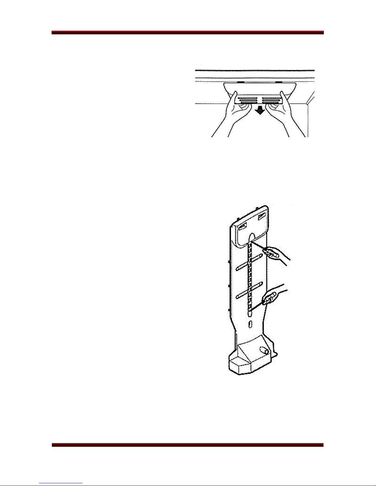
MULTI DUCT
1. Remove the upper and lower
caps using a small screwdriver.
2. Remove the two screws holding
the duct in place.
3. Pull the duct away from the back
of the refrigerator from the top.
4. Disconnect the lead wire at the
bottom of the duct before pulling
the duct out any farther.
5. Replacement is the reverse of
disassembly.
LFX21960ST/LFX25960xx Page 27 of 75 TRAINING MANUAL

REFRIGERATOR ICEMAKER
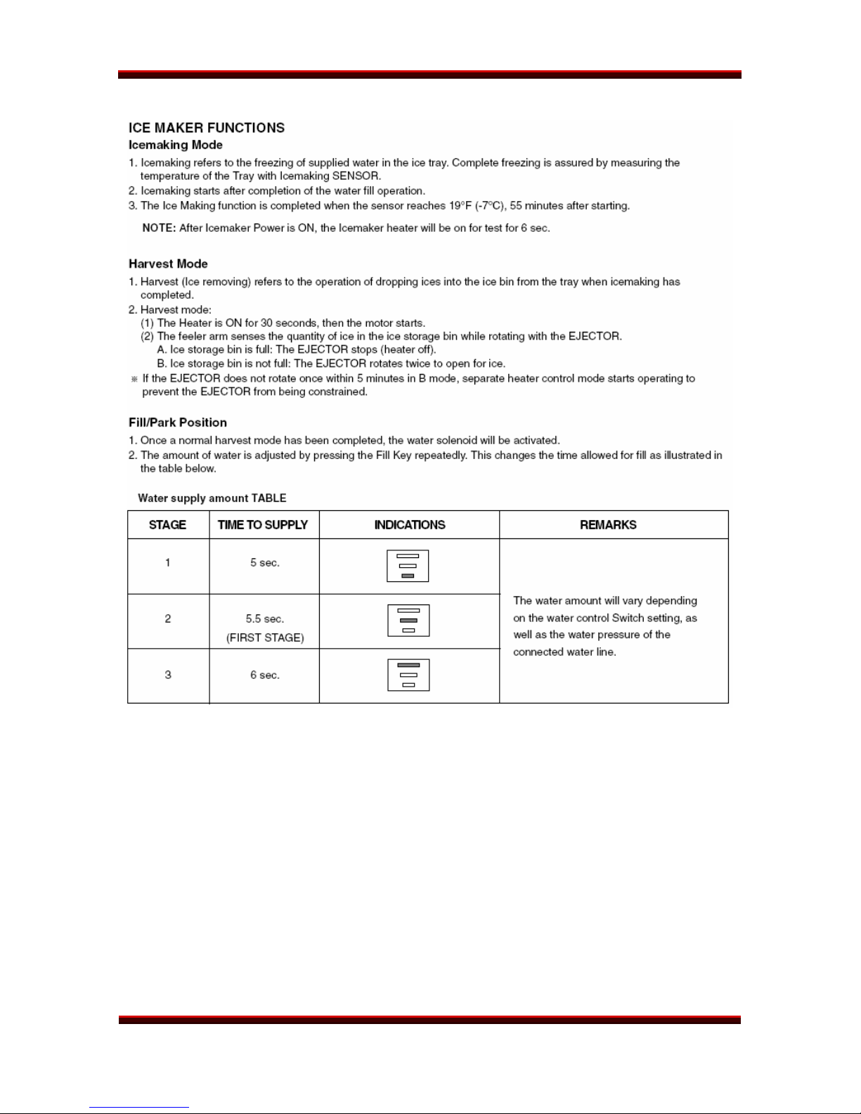
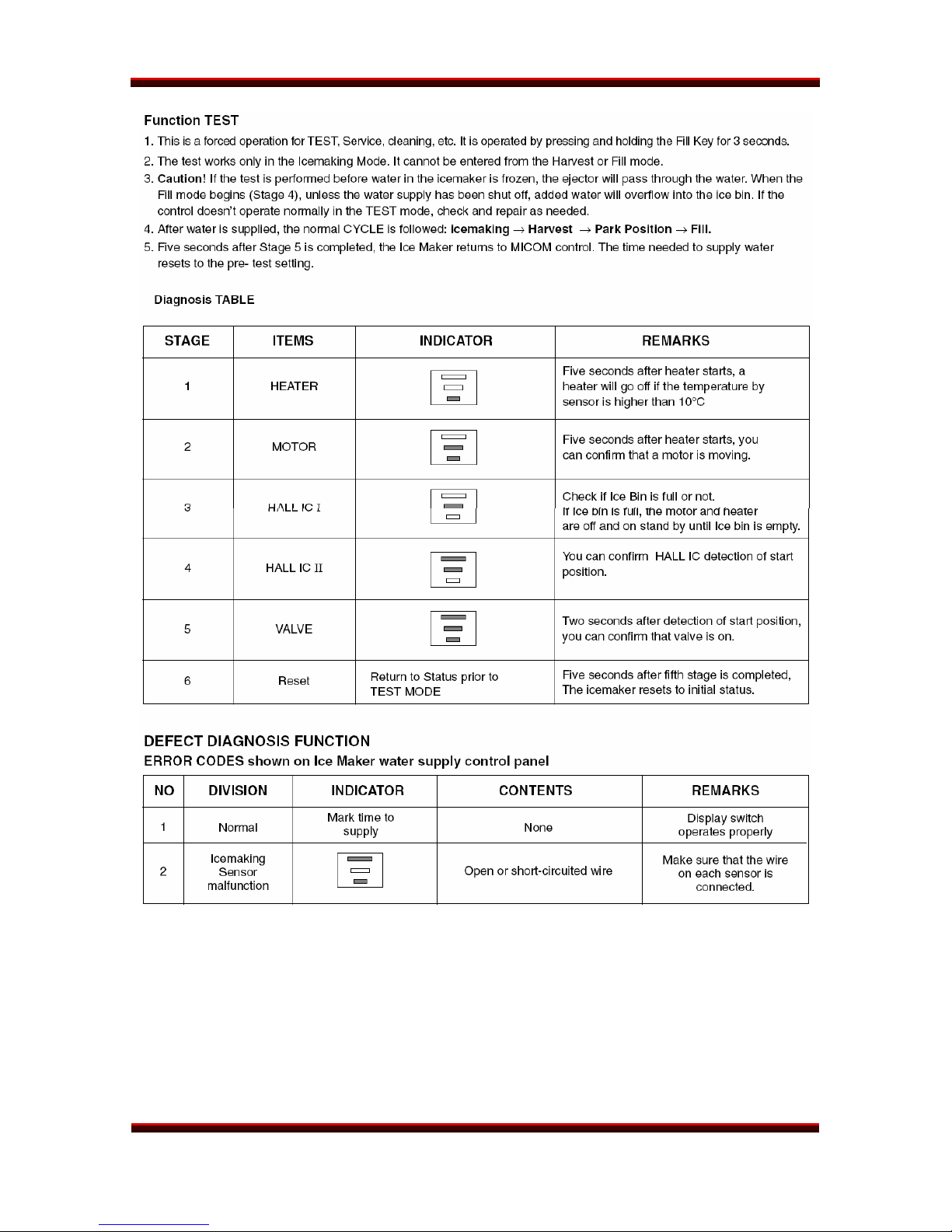
ICEMAKER
THEORY OF OPERATION
Turn the icemaker switch OFF and then ON again to reset it.
LFX21960ST/LFX25960xx Page 28 of 75 TRAINING MANUAL
REFRIGERATOR ICEMAKER
LFX21960ST/LFX25960xx Page 29 of 75 TRAINING MANUAL
REFRIGERATOR ICEMAKER
LFX21960ST/LFX25960xx Page 30 of 75 TRAINING MANUAL
 Loading...