

LG LFCS22520 series, LFNS22520 series Service Manual
REFRIGERATOR
SERVICE MANUAL
CAUTION
BEFORE SERVICING THE UNIT,
READ THE SAFETY PRECAUTIONS IN THIS MANUAL.
Models:
LFCS22520*
LFNS22520*
Colors:
Stainless (ST)
Smooth Black (SB)
Super White (SW)

CONTENTS
SAFETY PRECAUTIONS ………………………………………………………………… …..
1. Specifications …………………………………………………………………………
2. Parts Identification …………………………………………………………………….........................
3. Disassembly ………………………………………………………………………….................……....
Removing and Replacing the refrigerator door …………………………..................................
Door …………………………………………………………………………………………………..
Door Alignment ………………………………………………………………………........………..
Fan and Fan Motor (Evaporator) ………………………………………………................………
Defrost Control Assembly ………………………………………………………………................
Lamp …………………………………………………………………………………………….……
Multi Duct ………………………………………………………………………………….....………
Main PWB …………………………………………………………………………………....………
How to remove and reinstall the pullout drawer ………………………..............................……
Pull out drawer ……………………………………………………………........……………………
Cover Assembly T/V ...............................................................................................................
4. Adjustment ……………………………………………………………………..................……………..
Compressor ……………………………………………………………….....………………………
Introduction of e-linear compressor …………………………………….....................…………..
5. Circuit Diagram …………………………………………………………..................…………………..
6. PCB Picture ………………………………………………………...............……………………………
7. Troubleshooting with error display ………………………................................…………………..
8. Troubleshooting without error display …………………..............................……………………..
9. Reference ………………………………………………………………….............……………………..
10. Component Testing Information …………………………………….............................………….
11. Troubleshooting …………………………………………………....................………………………
12. Ice Maker and Dispenser working principles and repair …................................……………..
13. Description of function & Circuit Micom ………………………..............................…………….
……………
………………....
2
3-4
5
6-11
6
6
7
7
7
8
8
8
9-10
11
11
12
12
12
13
14-15
16-25
26-31
32-35
36-39
40-51
52-51
56-60
SAFETY PRECAUTIONS
Please read the following instructions before
servicing your refrigerator.
1. Unplug the power before handling any electrical
components.
2. Check the rated current, voltage, and capacity.
3. Take caution not to get water near any electrical
components.
4. Use exact replacement parts.
5. Remove any objects from the top prior to tilting
the product.
2
1. SPECIFICATIONS
SPECIFICATIONS
Color
Dimensions (W*D*H)
Net Weight 237.4 Lb
Capacity 22cuft
Refrigerant R134a
Climate class Temperate (N)
Rated Rating 115V~ / 60Hz
Cooling System Fan Cooling
Temperature Control MICOM control
Defrosting System
Insulation Polyurethan
Compressor FLA075LANA
Evaporator Fin Tube Type
GENERAL FEATURES
Condenser Aluminum Condenser
Lubricanting Oil Polyol Ester (POE) RL-7H/7 cst 220 ± 10 cc
Drier MOLECULAR SIEVE XH-7
Capillary Tube
First Defrost 4 Hours
Defrost Cycle 7 - 40 Hours
Desfrosting Device Heater, Sheath
Anti-freezing Heater Water Tank Heater
Case Material Embo (normal)
Door Material
Handle Type Vista-Handle(Al)
Basket, Quantity 6 Full + 2 Small
Cover, T/V Optibin Crisper + Humidity Control
Lamp High Brightness LED
Shelf 2Fix(full)
REFRIGERATOR
Tray meat No
Tray Egg No
Tray Vegetable Yes (2)
Pantry Yes
Basket, Quantity No
Lamp LED (Capsule)
Shelf No
Ice Maker
Ice Tray & Bank Ice Bin
FREEZER
Tray Drawer (F/U) Yes (Full Width)
Tray Drawer (F/C) No
Tray Drawer (F/L) Yes (plastic)
MODELS
LFCS22520B LFCS22520S LFCS22520W
Western Black Stainless Super White
(32 3/4 x 35 1/2 x 68 1/2) in
Full Automatic
Heater Defrost
ID Ø0.75
PCM Stainless PCM
Twisting
3
1. SPECIFICATIONS
SPECIFICATIONS
Color
Dimensions (W*D*H)
Net Weight
Capacity
Refrigerant
Climate class
Rated Rating
Cooling System
Temperature Control
Defrosting System
Insulation
Compressor
Evaporator
GENERAL FEATURES
Condenser
Lubricanting Oil
Drier
Capillary Tube
First Defrost
Defrost Cycle
Desfrosting Device
Anti-freezing Heater
Case Material
Door Material
Handle Type
Basket, Quantity
Cover, T/V
Lamp
Shelf
REFRIGERATOR
Tray meat
Tray Egg
Tray Vegetable
Pantry
Basket, Quantity
Lamp
Shelf
Ice Maker
Ice Tray & Bank
FREEZER
Tray Drawer (F/U)
Tray Drawer (F/C)
Tray Drawer (F/L)
LFNS22520S
MODELS
Stainless
(32 3/4 x 35 1/2 x 68 1/2) in
252.9 Lb
22cuft
R134a
Temperate (N)
115V~ / 60Hz
Fan Cooling
MICOM control
Full Automatic
Heater Defrost
Polyurethan
FLA075LANA
Fin Tube Type
Aluminum Condenser
Polyol Ester (POE) RL-7H/7 cst 220 ± 10 cc
MOLECULAR SIEVE XH-7
ID Ø0.75
4 Hours
7 - 40 Hours
Heater, Sheath
Water Tank Heater
Embo (normal)
Stainless
Vista-Handle(Al)
6 Full + 2 Small
Optibin Crisper + Humidity Control
High Brightness LED
2Fix(full)
No
No
Yes (2)
Yes
No
LED (Capsule)
No
Install/ Ready
Ice Bin
Yes (Full Width)
No
Yes (plastic)
3
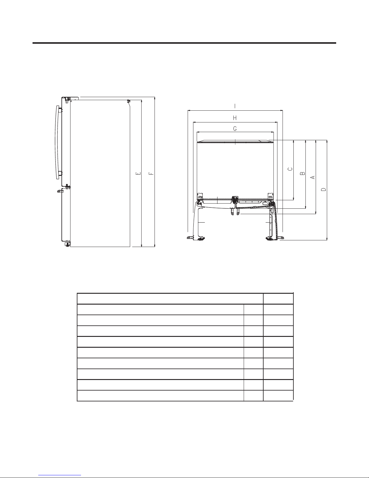
Depth with Handles A 35 1/2
Depth w/o Handles B 33
Depth w/o Doors C 29
Depth (Total with door open) D 44 3/4
Height to Top of Door Hinge E 68 1/2
Height to Top w/out Hinge F 67 1/4
Width G 29 3/4
Width (door open 90 deg. w/o handle) H 33 1/4
Width (door open 90 deg. with handle) I 38 1/4
Description
22cuft
4
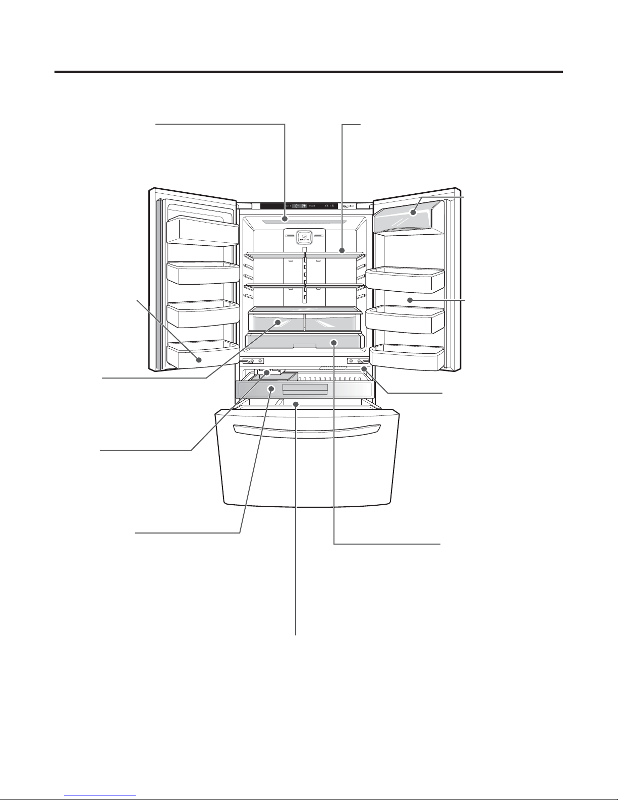
2. PARTS IDENTIFICATION
LED interior lamps
The interior lamps light up
the inside of the
refrigerator.
Fixed Door Bin
Used to preserve
chilled food or
drinks.
Crisper
Controls humidity and helps
vegetables and fruit to stay crisp.
**Replace the cover assembly imply as
first step remove the door refrigerator.
Adjustable Refrigerator Shelf
The shelves in your refrigerator are
adjustable to meet your individual
storage needs. (Half or full type)
Dairy Product Bin
Used to preserve
dairy products. (some
models only)
Modular Door Bins
Interchangeable bins
can be arranged to suit
your storage needs.
Auto Closing Hinge
The refrigerator doors and
freezer drawers close
automatically when you push
them slightly.
Ice Bin
Ice cubes are automatically
produced.
(Ice Maker installed only)
Pullout Drawer
Used for extra storage within the
freezer compartment.
(The door only closes
automatically when it is open
at an angle of less than 30°).
Glide'N'Serve
Used for large party trays,
deli items and beverages.
Durabase® and Durabase® Divider
The Durabase is a storage space
recommended for the preservation of
large food items. The Durabase Divider
is used to organize the Durabase area
into sections.
It can be adjusted from side to side to
accommodate items of different sizes.
5
3. DISASSEMBLY
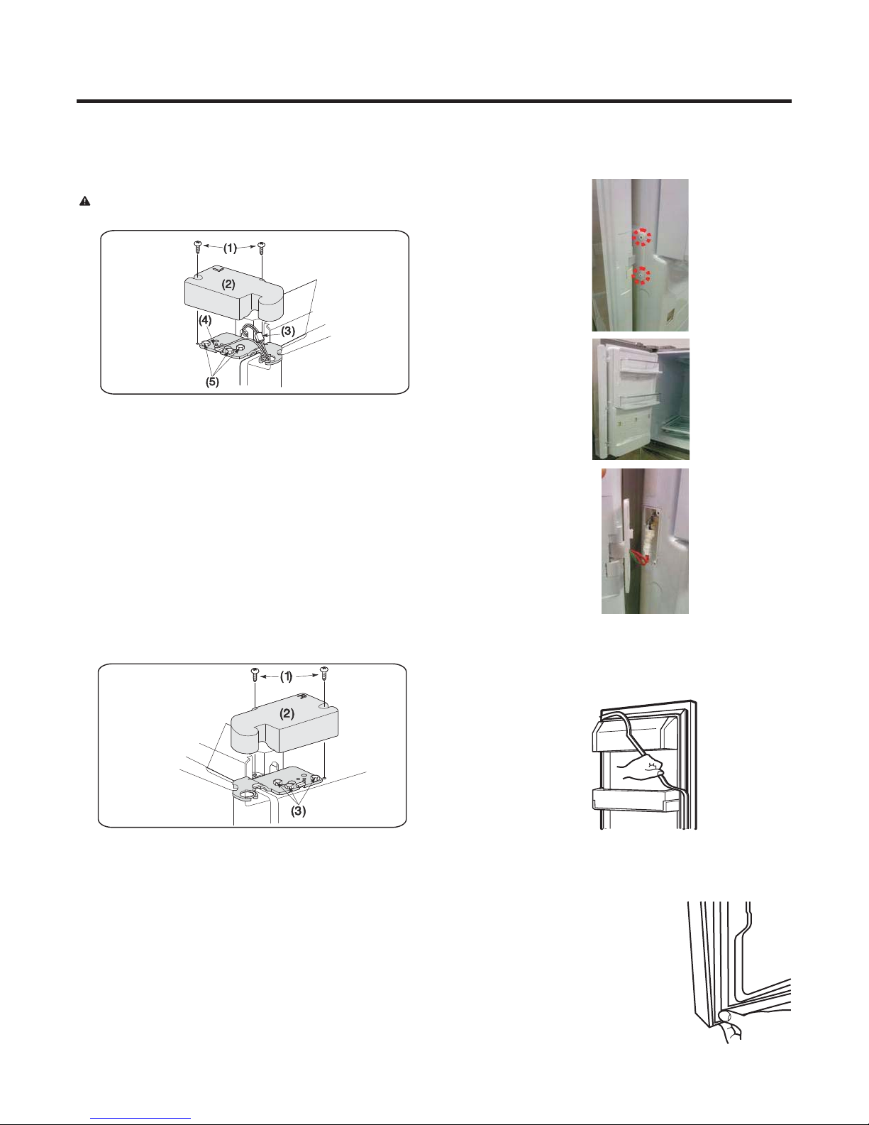
3-1 REMOVING AND REPLACING REFRIGERATOR
DOOR
To remove and replace the refrigerator door:
CAUTION: Before you begin, remove food and
bins from the doors.
• Open the door. Remove the top hinge cover screw (1) and
screw (1) and lift up the cover(2).
• Remove the cover.
• Disconnect wire harnesses (3).
• Remove the grounding screw (4).
• Using 10mm or 13/32-inch socket wrench, remove the 3 bolts
and lift off the Top Hinge(5). Set parts aside.
IMPORTANT
door does not fall forward.
• Lift the door from the middle hinge pin and remove the door.
• Place the door, inside facing up, on a non-scratching surface.
• Replace in the reverse order.
: When removing the bolts, be careful that the
3-2 DOOR
• Mullion Removal
1. Remove 2 screws.
2. Lift mullion up carefully.
3. Disconnect wire harness.
To remove the right refrigerator door:
• Open the door. Remove the top hinge cover screw (1) and
screw (1) and lift up the cover(2).
• Remove the cover.
• Disconnect wire harnesses (3).
• Remove the grounding screw (4).
• Using 10mm or 13/32-inch socket wrench, remove the 3 bolts
and lift off the Top Hinge(5). Set parts aside.
IMPORTANT
door does not fall forward.
• Lift the door from the middle hinge pin and remove the door.
• Place the door, inside facing up, on a non-scratching surface.
• Replace in the reverse order.
: When removing the bolts, be careful that the
• Door Gasket Removal
1. Remove gasket.
Pull gasket free from gasket channel of the four remaining
sides of door.
• Door Gasket Replacement
1. Insert gasket into channel
Press gasket into channels on the four remaining
sides of door.
• Mullion Replacement
1. Connect wire harness.
2. Insert mullion into channel.
Inserting mullion assy’ into bracket, door.
3. Assemble 2 screws.
6
• Mullion Replacement
1. Connect wire harness.
<22cu.ft>
If the space between your doors is uneven, follow the
instructions below to align the doors
With one hand, lift up the door that you would like to raise at
the middle hinge. With your other hand, use pliers to insert
snap ring as shown. Insert additional snap rings until the doors
are aligned.
(Three snap rings are provided with the refrigerator in the Use
& Care Guide packet).
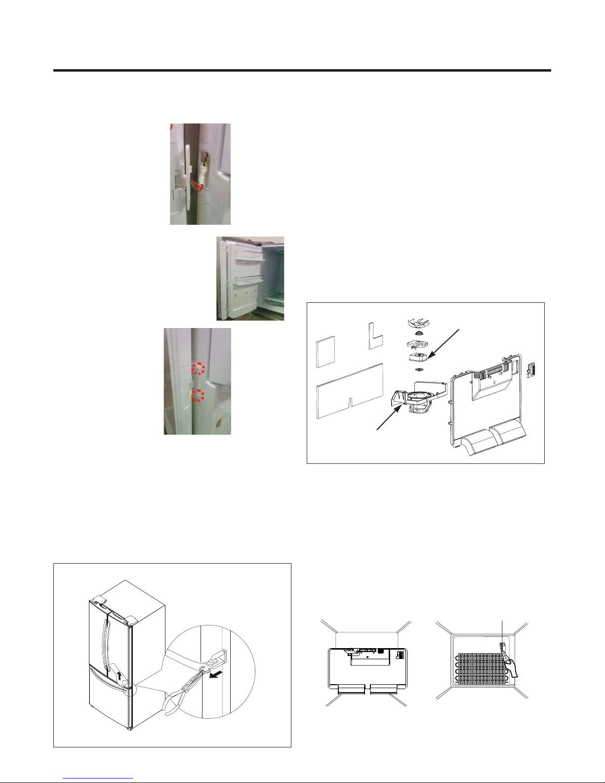
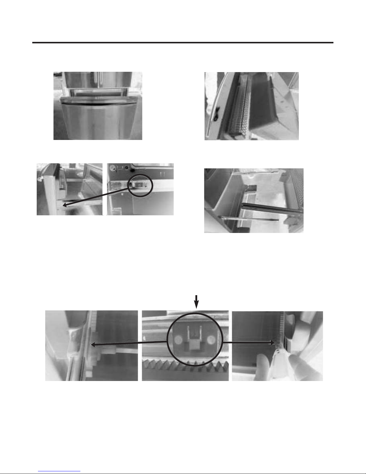
3-4 FAN AND FAN MOTOR(EVAPORATOR)
2. Insert mullion into channel.
Inserting mullion assy’ into bracket, door.
3. Assemble 2 screws.
3-3 DOOR ALIGNMENT
<24cu.ft>
If the space between your doors is uneven, follow the
instructions below to align the doors:
Turn the leveling legs (CCW) to raise or (CW) to lower the
height of the front of the refrigerator by using flat blade screw
driver or 11/32" wrench. Use the wrench (Included with the
User Manual) to adjust the bolt in the door hinge to adjust the
height. (CCW to raise or CW to lower the height).
1. Remove the freezer drawer. (If your refrigerator has an
icemaker, remove the icemaker first).
2. Remove the grille by pulling the grille forward.
3. Remove the Fan Motor assembly by loosening 3 screws
and disassembling the shroud.
4. Pull out the fan and separate the Fan Motor and Bracket.
FAN MOTOR
Shroud
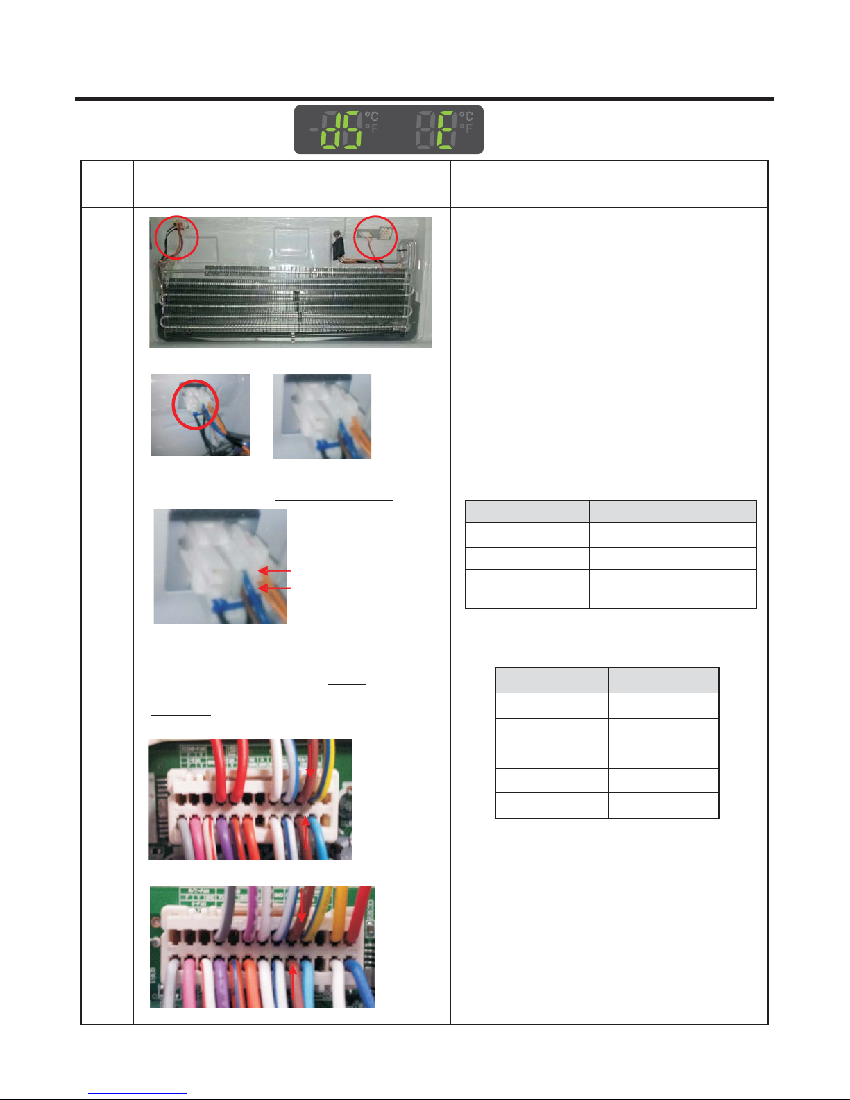
3-5 DEFROST CONTROL ASSEMBLY
Defrost Control assembly consists of Defrost Sensor and
FUSE-M.
The Defrost Sensor works to defrost automatically. It is
attached to the metal side of the Evaporator and senses its
temperature. At 46F(8°C), it turns the Defrost Heater off.
Fuse-M is a safety device for preventing over-heating of
the Heater when defrosting.
1. Pull out the grille assembly. (Figure 1)
2. Separate the connector with the Defrost Control assembly
and replace the Defrost Control assembly after cutting the Tie
Wrap. (Figure 2)
GRILLE ASSEMBLY
DEFROST-CONTROL
ASSEMBLY
Figure 1
Figure 2
7
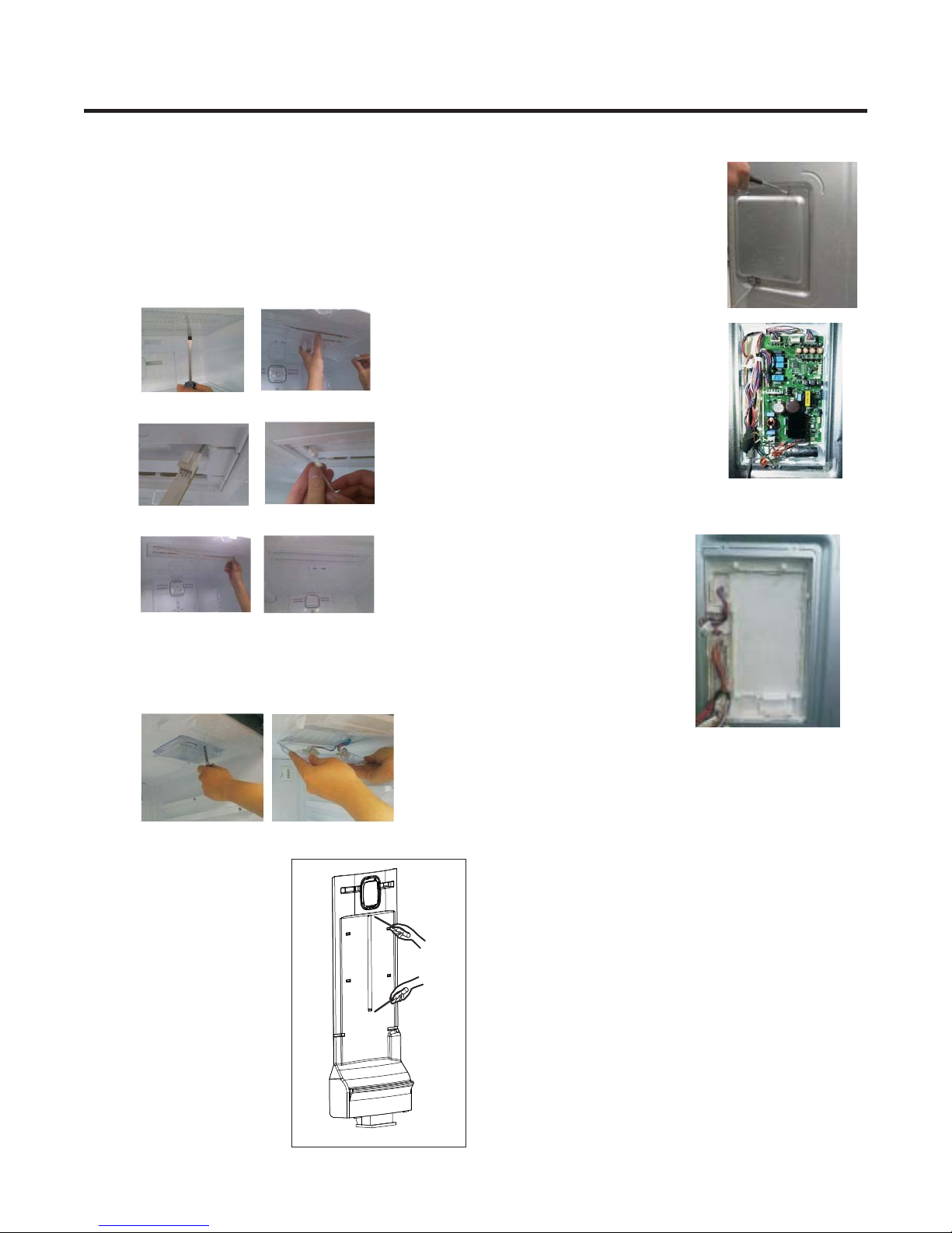
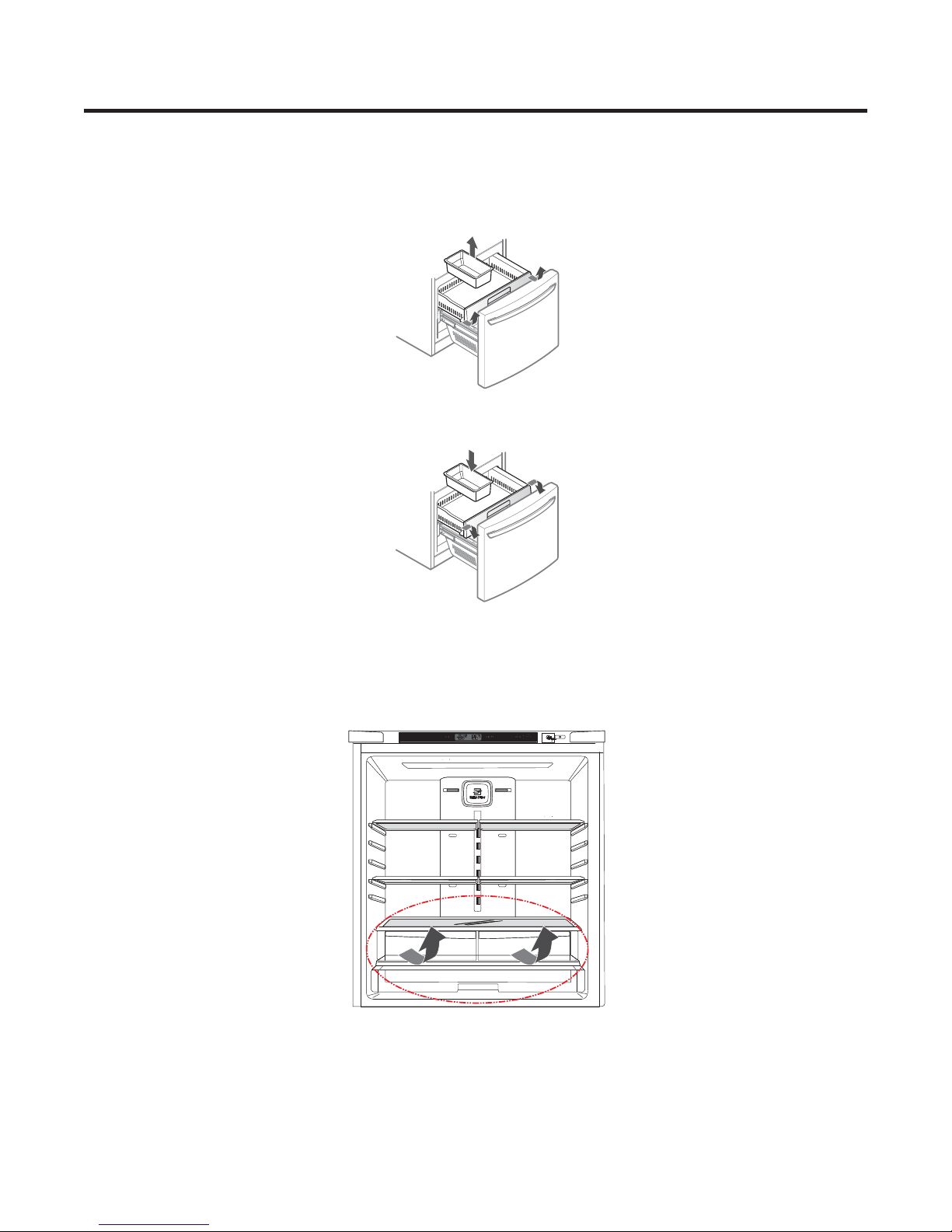
3-6 LAMP
Unplug Refrigerator, or disconnect power at the circuit
breaker.
If necessary, remove top shelf or shelves.
3-6-1 Refrigerator Compartment Lamp
1) Unplug refrigerator power cord from electric outlet.
2) Put flat screwdriver into service hole and remove cover
of refrigerator light.
3) Remove the LED assembly from connector.
4) Replace the LED assembly.
3-8 MAIN PWB
1) Loosen 3 screws on the PWB cover.
2) Remove the PWB cover.
3) Disconnect wire harness and replace the main PWB in the
reverse order of removal.
3-6-2 Freezer Compartment Lamp
1. Unplug refrigerator power cord form outlet.
2. Remove screw with driver.
3. Grasp the cover Lamp, pull the cover downward.
3-7 MULTI DUCT
1. Remove the upper and lower
caps by using a flat screwdriver,
and remove 2 screws.
(Figure 3)
2. Disconnect the lead wire on
the bottom position.
Figure 3
8
3-9 HOW TO REMOVE AND REINSTALL THE PULLOUT DRAWER
Step 1) Open the freezer door.
Step 3) Remove the two screws from the guide rails (one
from each side).
Step 5) First: Remove the gear from the left side first by releasing the tab behind the gear, place a screwdriver between the
gear and the tab and pull up on the gear.
Second: Remove the center rail.
Third: Remove the gear from the right side by following the same steps for the left side.
Step 2) Remove the lower basket.
Step 4) Lift the freezer door up to unhook it from the rail
support and remove.
Pull both rails to full extension.
NOTE: THIS TAB MUST BE PUSHED IN TO RELEASE THE GEAR.
9
3-9-2 Follow Steps to Reinstall
Step 1) Reinstall the right side gear into the clip.
Step 2) Insert the rail into the right side gear. Gears do not
need to be perpendicular to each other.
Step 4) The rail system will align itself by pushing the rails all
the way into the freezer section.
Pull the rails back out to full extension.
Step 6) Reinstall the two screws into the guide rails
(one from each side).
Step 3) Insert the rail into the left side gear, and insert the
gear into the clip.
Step 5) Reinstall the freezer door by inserting the rail tabs into
the guide rail.
Step 7) Reinstall the lower basket, and close the freezer
door.
10
3-10 PULL OUT DRAWER
Top Drawer
1. To remove the Top drawer.
Pull the drawer out to full extension. Lift the front of the drawer up, then pull it straight out.
2. To install, slightly tilt up the front and insert the drawer into the frame and push it back into push it back place.
3-11 COVER T/V ASSEMBLY
1) Refer to sections “How to remove the left refrigerator door” and “How to remove the right refrigerator door” in order to move
the doors and then replace the cover assembly t/v
2) Pull out the cover assembly t/v.
11
4. ADJUSTMENT
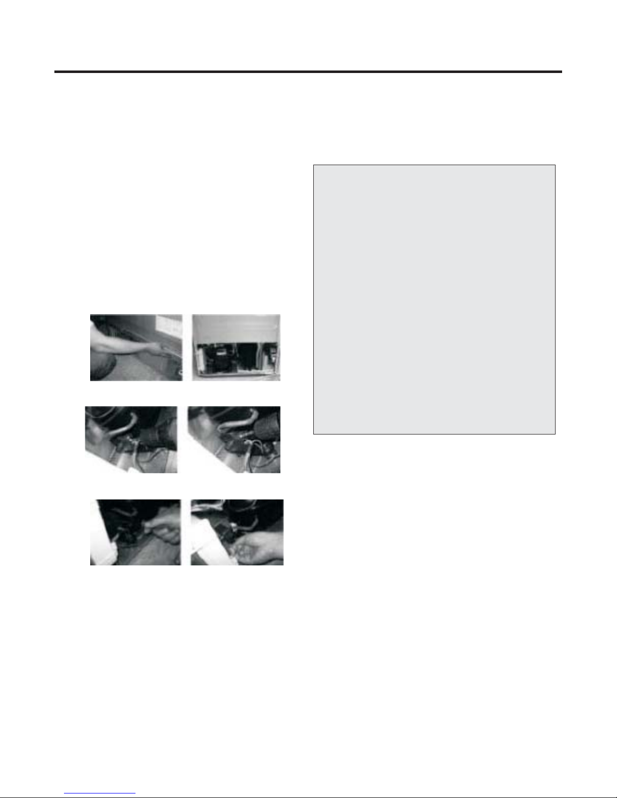
4-1 COMPRESSOR
4-1-1 Role
The compressor intakes low temperature and low pressure
gas from the evaporator of the refrigerator and compresses
this gas to high-temperature and high-pressure gas. It then
delivers the gas to the condenser.
4-1-2Note for Usage
(1) Be careful not to allow over-voltage and over-current.
(2) Do not drop or handle carelessly.
(3) Keep away from any liquid.
If liquid such as oil or water enters the Cover PTC
Compressor may fail due to breakdown of their insulating
capabilities.
(4)Always use the Parts designed for the compressor and
make sure it is properly attached to the compressor.
Parts may appear physically identical but could have different
electrical ratings. Replace parts by part number and model
number. Use only approved substitute parts.
4-1-3 Remove the cover PTC
(1)Remove the Cover Back M/C
4-2-3 Compressor protection logic
Since linear Comp conducts linear reciprocating motion, we
have protection logic for compressor, motor and PCB as the
below.
- Stroke Trip
During the operation, if stroke is above the target value,
decrease the target volt by 3V.
- Current Trip
Current trip is set in order to protect compressor mechanical
part and drive from the overcurrent that might arise during
the operation.
Check the current for every 416.7us and if the Trip exceeds
1.86Arms more than three times at Comp ON, forcibly stop
and restart six minutes later.
- Lock Piston Trip
If stroke is under 5mm even if the current is more than
14Arms, Take it as ‘piston lock’ and restart after 2’30” of
Comp OFF. Check the current and stroke for every 416.7us
and if the condition fits more than three times at Comp ON,
the Trip occurs.
- IPM fault Trip
It occurs if FO signal received from IPM is LOW. For every
416.7us, check whether FO signal is LOW. The tripoccurs if
it is found three times during the five periods(83ms).
(2)Remove two screws on comp base
(3)Use a L-shaped flap tool to pry off the cover.
(4)Assembly in reverse order of disassembly.
12
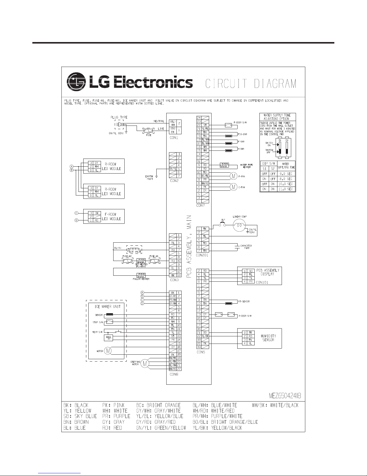
5. CIRCUIT DIAGRAM
13
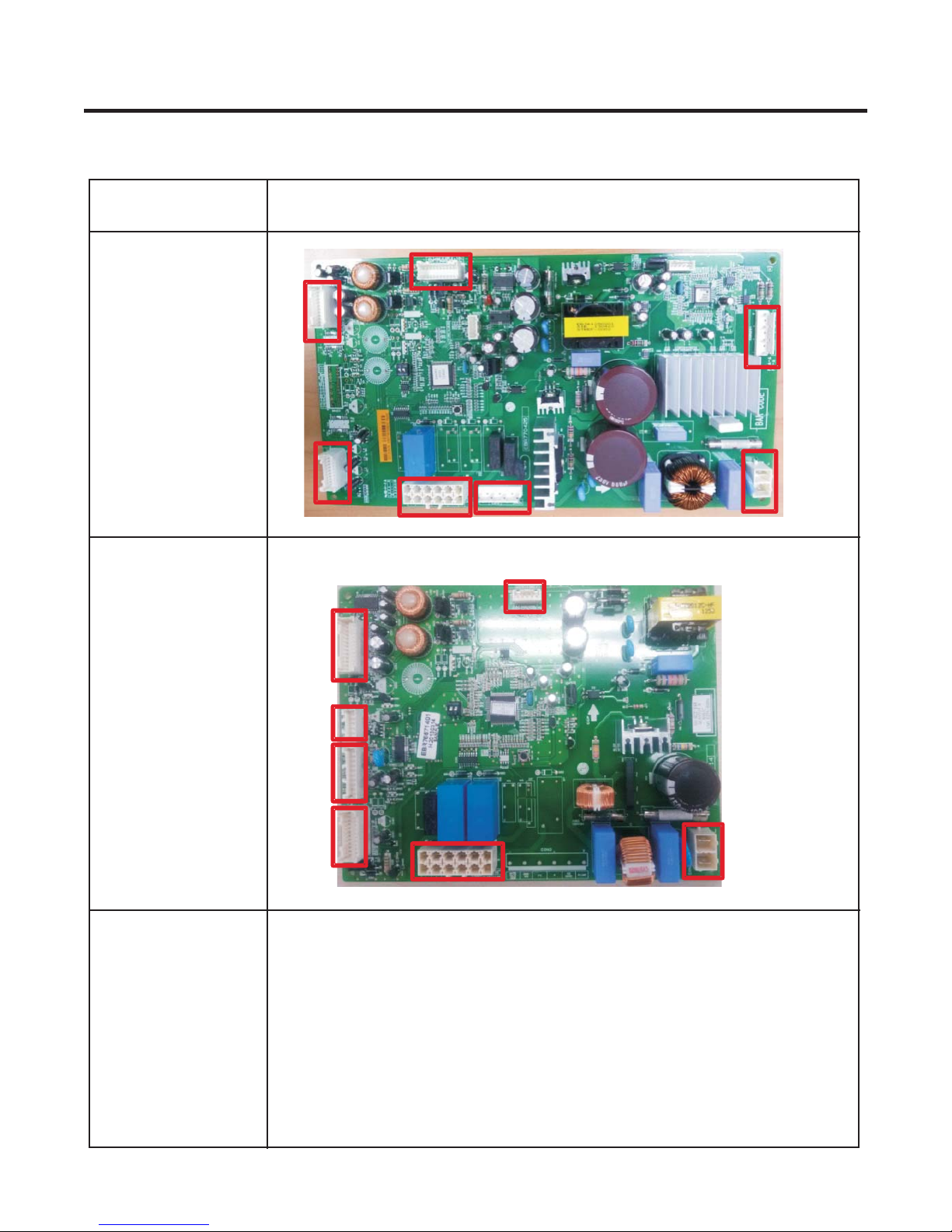
6. PCB PICTURE
6-1 Main PCB
P/No & MFG
Drawer
EBR770425**
(2013.05~)
Swing
EBR766714**
(.~)
2013 05
CON7
CON5
CON7
Picture
CON8
CON201
CON1
CON3 CON2
CON8
CON9
CON4
CON5
CON3 CON1
14
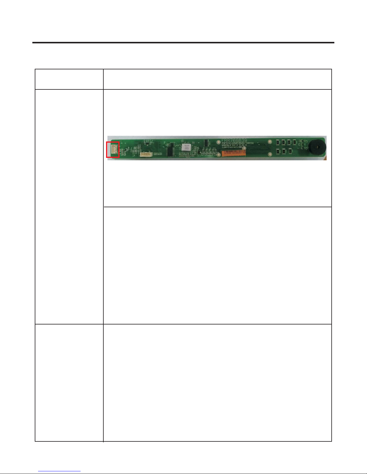
6-2 Display PCB & Sub PCB
P/No Picture
CON01
EBR766839**
(2013.05~)
15
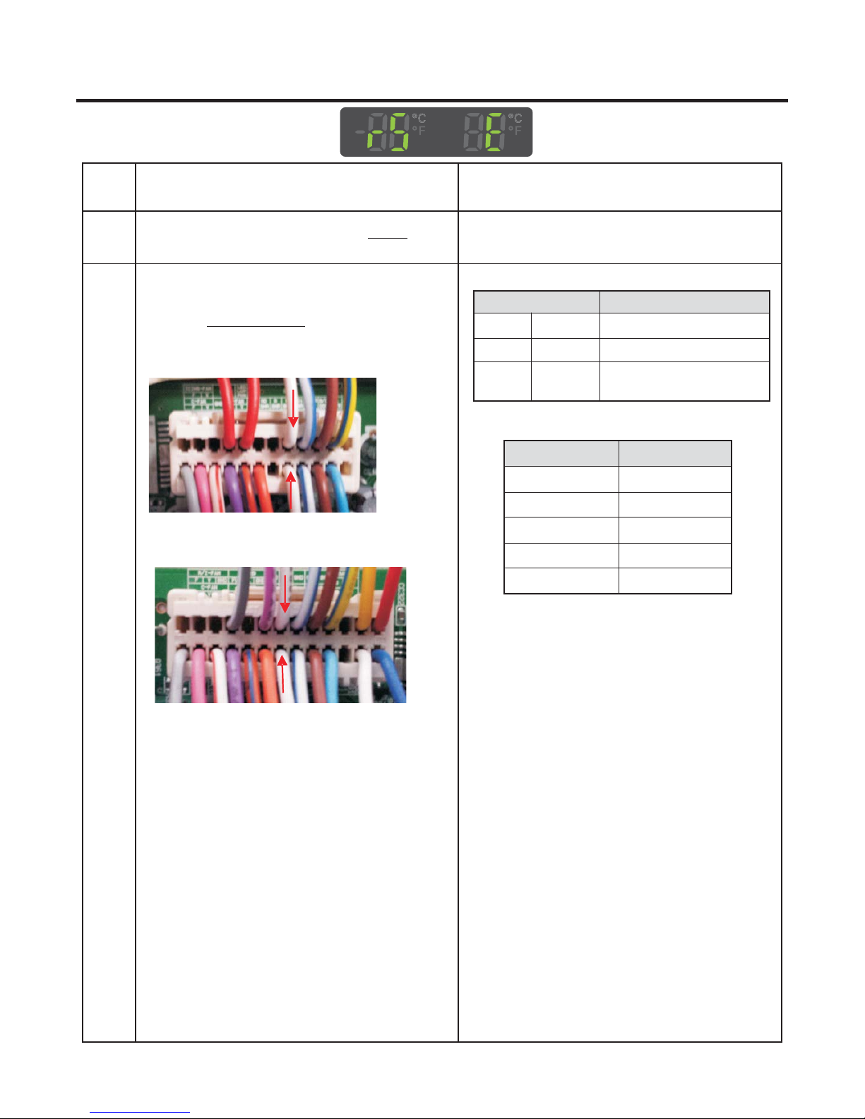
7. TROUBLESHOOTING WITH ERROR DISPLAY
7-1 Freezer Sensor Error (FS E)
No
1
2
Checking flow
Check for loose connection in .CON7
1-. Unplug connector from CON7.
2-. Check resistance between
wires .Blue/White to Blue/White
<Drawer Model>
<Swing Model>
Result & SVC Action
Result SVC Action
Ω
0
OFF
Other
-22°F / -30°C
-13°F / -25°C
Short
Open
Normal
<Temperature table-1>
Temperature
-4°F / -20°C
5°F / -15°C
14°F / -10°C
Change the sensor
Replace the refrigerator
Check the Temp and
resistance (Table-1)
40.5 ~ 38.5 ㏀
30.5 ~ 28.5 ㏀
23 ~ 21.5 ㏀
17.5 ~ 16.5 ㏀
13.5 ~ 12.5 ㏀
Result
23°F / -5°C
32°F / 0°C
※
The sensor is determined by
the temperature.
For example, 23㏀ indicates -4°F.
10.5 ~ 9.5 ㏀
8 ~7.5 ㏀
16
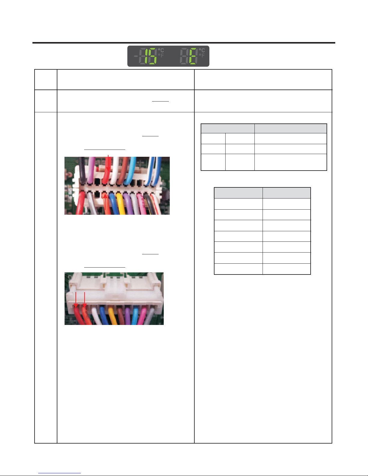
7-2 Refrigerator Sensor Error (rS E)
No
1
2
Checking flow
Check for loose connection in .CON7
1-. Unplug connector from CON7.
2-. Check resistance between
wires .White to White
<Drawer Model>
<Swing Model>
Result & SVC Action
Result SVC Action
Ω
0
OFF
Other
Short
Open
Normal
Change the sensor
Replace the refrigerator
Check the Temp and
resistance (Table-2)
<Temperature table-2>
Temperature
23°F / -5°C
32°F / 0°C
41°F / 5°C
50°F / 10°C
59°F / 15°C
38.5 ~ 36.5 ㏀
30.5 ~ 29.5 ㏀
24.5 ~ 23.5 ㏀
20 ~ 19 ㏀
16 ~15.5 ㏀
Result
※
The sensor is determined by
the temperature.
For example, 30㏀ indicates 32°F.
17
7-3 Icing Sensor Error (IS E)
No
1
2
Checking flow
Check for loose connection in .CON8
<Drawer Model>
1-. Unplug connector from .
CON8
2-. Check resistance between
wires .
Red to Orange
<CON8>
<Swing Model>
1-. Unplug connector from .
CON4
2-. Check resistance between
wires .
Red to Orange
Result & SVC Action
Result SVC Action
Ω
0
OFF
Other
Short
Open
Normal
Change the sensor
Replace the refrigerator
Check the Temp and
resistance (Table-1)
<Temperature table-1>
Temperature
-22°F / -30°C
-13°F / -25°C
-4°F / -20°C
5°F / -15°C
14°F / -10°C
23°F / -5°C
32°F / 0°C
40.5 ~ 38.5 ㏀
30.5 ~ 28.5 ㏀
23 ~ 21.5 ㏀
17.5 ~ 16.5 ㏀
13.5 ~ 12.5 ㏀
10.5 ~ 9.5 ㏀
8 ~7.5 ㏀
Result
<CON4>
※
The sensor is determined by
the temperature.
For example, 23㏀ indicates -4°F.
18
7-4 Defrost Sensor Error (dS E)
No
1
2
Checking flow
(1) (2)
Check for a loose connection.
(2)
1. Check the wires .Orange to Orange
Result & SVC Action
Result SVC Action
Ω
0
OFF
Other
Short
Open
Normal
Change the sensor
Replace the refrigerator
Check the Temp and
resistance (Table-3)
2.- Check for loose connection in CON7
from Main PCB.
3-. Unplug connector from .
CON7
4-. Check resistance between wires
to Brown
.
<Drawer Model>
<Swing Model>
<CON7>
Brown
<Temperature table-3>
Temperature
23°F / -5°C
32°F / 0°C
41°F / 5°C
50°F / 10°C
59°F / 15°C
※
The sensor is determined by
Result
38.5 ~ 36.5 ㏀
30.5 ~ 29.5 ㏀
24.5 ~ 23.5 ㏀
20 ~ 19 ㏀
16 ~15.5 ㏀
the temperature.
For example, 23㏀ indicates -4°F.
19
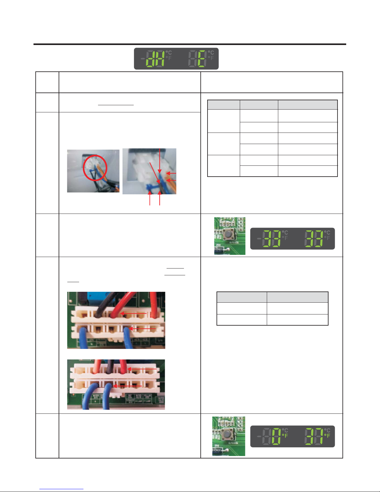
7-5 Defrost Heater Error (dH E)
No
1
2
Check the .Door gasket
1.- Check for loose connection in defrost
Checking flow
control part connector.
2-. Check resistance of defrost control part.
3 Input Test 3 Mode.
(Push the button 3 times)
Fuse M
Def’
Heater
Def’
Sensor
Result & SVC Action
Part Result SVC Action
Ω
0
Go to the 3
Fuse-M
Change Fuse-M
Go to the 3
Change Fuse-M
Go to the 3
Go to the 5
Def’
Heater
Def’
Sensor
Other
34 ~ 42
Other
Ω↓
21
Other
Ω
4
2-. Check voltage between wires
.
Red
<Drawer Model>
<Swing Model>
5 Release the test mode.
Push the button 1 times. (Normal)
1.- Check for loose connection in .
CON3
Blue to
Result
112 ~ 116 V
0 V
SVC Action
Go to the 5
Replace Main PCB
20
 Loading...