

LG LF66105SS Owner’s Manual

Free Standing Gas Cooker
Installation and Operating Instructions
LF96105SS
LF66105SS
To avoid the risk of accidents or damage to the Gas Cooker,
it is essential to read these operating instructions
before it is installed or used for the first time.
And please keep this manual for later reference.
P/No.: MFL62060304
http://au.lge.com (Australia)
http://nz.lge.com (New Zealand)

Contents
Introduction ................................................................................. 3
1. Instructions for safe and proper use.......................................3
Instructions for the installer ...................................................... 6
2. Installation of the appliance....................................................6
3. Adaptation to different types of gas ......................................11
4. Final operations....................................................................14
Instructions for the user .......................................................... 17
5. Description of controls..........................................................17
6. Use of the hob ......................................................................19
7. Use of the oven ....................................................................22
8. Electronic programmer (Only on equipped models).............26
9. Available accessories...........................................................29
10. Cleaning and maintenance.................................................30
11. Extraordinary maintenance.................................................33
These instructions are valid only for the end user countries
whose identification symbols appear on the cover of this
manual.
INSTRUCTIONS FOR THE INSTALLER: these are for the
authorised person who must carry out a suitable check of the gas
system, install the appliance, set it functioning and carry out an
inspection test.
INSTRUCTIONS FOR THE USER: these contain user advice,
description of the commands and the correct procedures for
cleaning and maintenance of the appliance.
2

1. Instructions for safe and proper use
This manual is an integral part of the appliance and therefore must
be kept in its entirety and in an accessible place for the whole
working life of the cooker. We advise reading this manual and all
the instructions therein before using the cooker. Also keep the
series of nozzles supplied. Installation must be carried out by
qualified personnel in accordance with the regulations in force. This
appliance is intended for domestic uses and conforms to current
regulations in force. The appliance has been built to carry out the
following functions: Cooking and heating-up of food. All other
uses are considered improper.
The manufacturer declines all responsibility for improper use.
Do not leave the packing in the home environment. Separate the
various waste materials and take them to the nearest special
garbage collection centre.
It is compulsory that the appliance be grounded according to the
methods required by safety rules.
The plug to be connected to the power cable and the socket must
be the same type and must conform to current regulations.
The socket must be accessible after the appliance has been built in.
Never unplug by pulling out the cable.
Immediately after installation carry out a brief inspection test of
the appliance, following the instructions below. Should the
appliance not function, disconnect it from the supply and call the
nearest technical assistance centre.
Never attempt to repair the appliance.
DO NOT USE OR STORE FLAMMABLE MATERIALS IN THE
APPLIANCE STORAGE DRAWER OR NEAR THIS
APPLIANCE.
3
Introduction
Introduction
DO NOT MODIFY THIS APPLIANCE
When not in use, make sure that the control knobs are in the
correct (OFF) position ●●.
Never put inflammable objects in the oven: They could be
accidentally catch fire and burn.
The I.D plate with technical date, serial number and brand name is
positioned visibly in the storage compartment.
The plate must not be removed.
Do not put pans without perfectly smooth and flat bottoms on the
hob grids.
During use the appliance becomes very hot. Take care not to
touch the heating elements inside the oven.
Do not use containers or broilers that extend beyond the outer
perimeter of the hob.
The appliance is designed for use by adults. Do not allow
children to go near or play with it.
When operating the grill all accessible parts could become very hot:
keep out of the way of children.
If the appliance is to be positioned on a platform it must be installed
in such a way as to prevent it from tilting off it.
This appliance is designed for cooking food and it shall not be used
as a space heater.
Do not spray aerosols in the vicinity of this appliance while it is in
operation.
4
Where this appliance is installed in marine craft or in caravans, it
shall not be used as a space heater.
Do not apply decorative panels to the lower part of the cooker as
they may prevent correct air circulation and cause overheating.
Before the appliance is put into operation, all the labels and
protective films applied inside or outside must be removed.
The manufacturer declines all responsibility for damage to
persons or things caused by non-observance of the above
prescriptions or by interference with any part of the appliance or
by the use of non-original spares.
5
Instructions for the installer
2. Installation of the appliance
It is the law that all gas appliances are installed by authorised
persons. Clearance around the cooker must comply with the
requirements of AS5601.
The manufacturer declines all responsibility for damage to
persons or things caused by non-observance of the above
prescriptions or by interference with any part of the appliance.
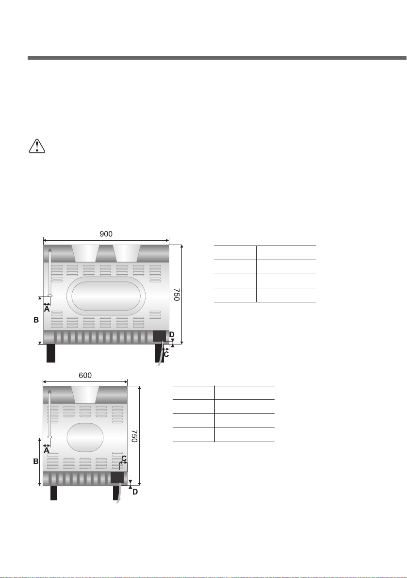
Overall dimensions: location of gas and electrical connection
points (all measures in mm).
6
A 60
B 410
C 60
D 70
A 60
B 410
C 100
D 150
2.1 Electrical connection
Make sure that the power line voltage matches the specifications
indicated on the rating plate located inside the storage compartment.
This rating plate must never be removed.
If the appliance is connected to the supply by means of a fixed
connection, install a multipolar cut-out device on the line, with
contact opening distance equal to or greater than 3 mm, located
near the appliance and in an easily reachable position.
Connection to the supply may be fixed or with plug and socket. In
the latter case the plug and socket must be suitable for the cable
employed and conform with the regulations in force.
Regardless of the type of connection, earthing of the appliance is
absolutely obligatory. Before connection make sure that the supply
line is suitably earthed. Avoid the use of reducers, adapters or shunts.
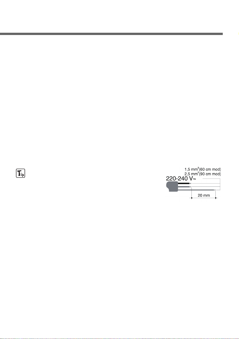
1. For operation on 220-240V~: use a
three-pole H05RR-F or H05V2V2-F cable
having a cross section of 3 x 2.5 mm
2
(90 cm wide models) or 3 x 1.5 mm
2
(60 cm wide models).
The cable end to be connected to the appliance must be provided
with ground wire (yellow-green) at least 20 mm longer.
7
8
Instructions for the installer
2.2 Gas connection
Use pipe-joint compound made for use with Natural and U.L.P. gas.
This appliance is suitable for installation with Natural
Gas or ULPG (propane). Refer to page 12 for the
relevant burner pressure and appropriate injector
sizes. When the appliance is to be connected to
Natural Gas then the pressure regulator supplied must
be fitted to the gas inlet. A test point (for checking the
gas pressure) is supplied either with the regulator or
as a separate fitting in the case of ULPG (propane) appliances.
Connection of the appliance to the gas supply must be in
accordance with the requirements of AS5601. A
1
/2” BSP connector
at the inlet is recommended and the gas supply line to the
appliance must be of adequate length to allow sufficient withdrawal
of appliance for service or disconnection and be:
1. annealed copper pipe or;
2. flexible hose according to AS/NZ1869 & be at least Class
“B”, 10 mm diameter.
The cooker must be installed with provision to allow the gas to be
turned off and disconnected for servicing and removal of the
appliance as required from the gas supply. Before the cooker is
operated make certain all relevant parts are placed in the correct
position.
When the installation is completed the installation connections of
cooker will require to be leak tested, the burner operating pressure
and flame checked and adjusted.
Warranty service calls do not cover these adjustments!
To check the operating pressure of the appliance it is recommended
at least 2 large size burners are used. Ensure appliance is secured
to wall when installation is completed.
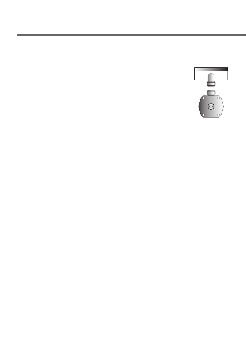
N.G. The regulator supplied must be fitted to the
1
/2” BSP thread at
the rear of the appliance. An approved manual shut-off valve must
be installed. The N.G. regulator must be checked and adjusted to
1.0kPa after installation.
9
U.L.P.G: Can be connected to the inlet fitting directly.
The pressure must be checked to ensure it is operating
at 2.75kPa. A separate test point fitting must be installed
between the piping & the appliance for the pressure to
be checked to ensure it is operating at 2.75kPa.
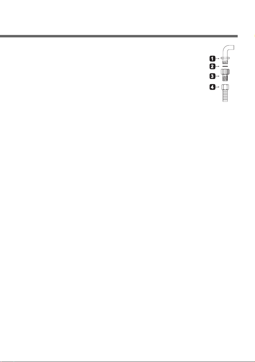
Make the connection to the gas mains using a continuous
wall flexible steel pipe whose specifications comply with
the current regulations. Carefully screw the connector 3 to the gas
connector 1 of the appliance, placing the seal 2 between them.
Apply a suitable sealing substance to the thread of the connector 3
and then tighten the flexible steel pipe 4 to the connector 3.
2.3 Combustion gas discharge
Combustion gases may be discharged by means of hoods
connected to a natural draught chimney or a fan extraction system.
An efficient extraction system requires precise planning by an
authorised specialist and must comply with the distances and
positions indicated by the regulations. After installation, the
specialist must issue a certificate of compliance.
2.4 Room ventilation
Caution – This cooker may only be installed and operated in rooms
permanently ventilated in accordance with current regulations. For
proper operation of a gas appliance it is essential for the air
necessary for combustion of the gas to be able to flow naturally into
the room. Air must flow directly into the room through openings in
its outside walls. This (these) opening (s) must have a free passage
cross-section of at least 100 cm
2
, or 200 cm2for appliances not
equipped with gas safety device. These openings must be
constructed so that they cannot be obstructed indoors or outdoors,
and should preferably be close to the floor on the side opposite to
the combustion gas discharge point. If it is not possible to make the
openings in the room where the cooker is installed, the necessary
air may be taken from an adjoining room, provided it is not a
bedroom or a room with fire risk.
Instructions for the installer
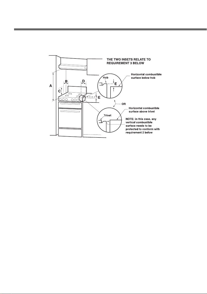
2.5 Clearance above and around domestic cookers
Extract from AS5601
REQUIREMENTS
1. Overhead clearances – (Measurement A)
Range hoods and exhaust fans shall be installed in accordance
with the manufacturer’s instructions. However, in no case shall
the clearance between the highest part of the hob of the cooking
appliance and a range hood be less than 600 mm or, for an
overhead exhaust fan, 750 mm.
Any other downward facing combustible surface less than 600
mm above the highest part of the hob shall be protected for the
full width and depth of the cooking surface area in accordance
with Clause 5.12.1.2. However, in no case shall this clearance to
any surface be less than 450 mm.
2. Side clearances – (Measurements B & C)
Where B, measured from the periphery of the nearest burner to
any vertical combustible surface, is less than 200 mm, the
surface shall be protected in accordance with Clause 5.12.1.2 to
10

a height C of not less than 150 mm above the hob for the full
dimension (width or depth) of the cooking surface area. Where
the cooking appliance is fitted with a ‘splashback’, protection of
the rear wall is not required.
3. Additional requirements for Freestanding and Elevated Cooking
Appliaces – (Measurements D & E)
Where D, the distance from the periphery of the nearest burner to
a horizontal combustible surface is less than 200 mm, then E
shall be 10 mm or more, or the horizontal surface shall be above
the trivet. See insets above.
NOTES
1. Requirement 3 does not apply to a freestanding or elevated
cooking appliance which is designed to prevent flames or the
cooking vessels from extending beyond the periphery of the
appliance.
2. The ‘cooking surface area’ is defined as that part of the appliance
where cooking normally takes place and does not include those
parts of the appliance containing control knobs.
3. For definition of hob, see Clause 1.4.64.
4. For definition of trivet, see Clause 1.4.109.
5. Consideration is to be given to window treatments when located
near cooking appliances. See Clause 5.3.4.
3. Adaptation to different types of gas
Before performing any cleaning or maintenance work, disconnect
the appliance from the mains.
The hob of the cooker is adjusted for use with either natural gas at
a pressure of 1.0kPa. In the case of operation with other types of
gas the burner nozzles must be changed and the minimum flame
adjusted on the gas taps. To change the nozzles, proceed as
described below.
11
 Loading...