

Page 1

Floor Standing Type
Air Conditioner
SERVICE MANUAL
MODEL: LF300CP(LP-C303R20)
LF480CE(LP-C483TA0)
Page 2

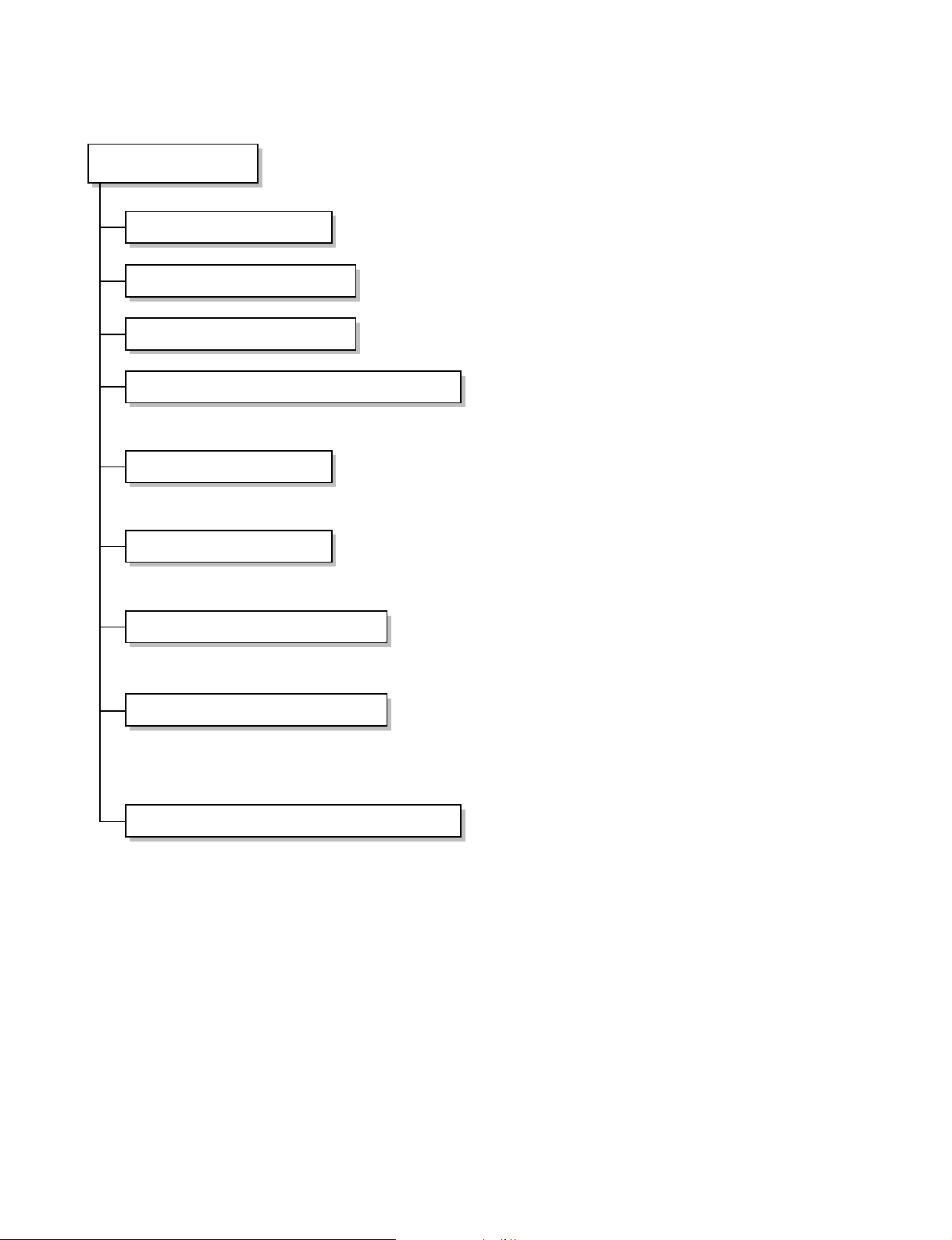
Contents
Safety Precautions..................................................................................................................3
Functions .................................................................................................................................7
Product Specifications .........................................................................................................10
Dimensions............................................................................................................................11
Wiring Diagram......................................................................................................................15
Operation Details ..................................................................................................................17
Installation of Indoor, Outdoor Unit.....................................................................................23
Test Running .........................................................................................................................25
Troubleshooting Guide .........................................................................................................27
Exploded View and Replacement Parts List.......................................................................41
–2–
Page 3
Safety Precautions
To prevent injury to the user or other people and property damage, the following instructions must
be followed.
■ Incorrect operation due to ignoring instruction will cause harm or damage. The seriousness is
classified by the following indications.
This symbol indicates the possibility of death or serious injury.
This symbol indicates the possibility of injury or damage to properties only.
■ Meanings of symbols used in this manual are as shown below.
Be sure not to do.
Be sure to follow the instruction.
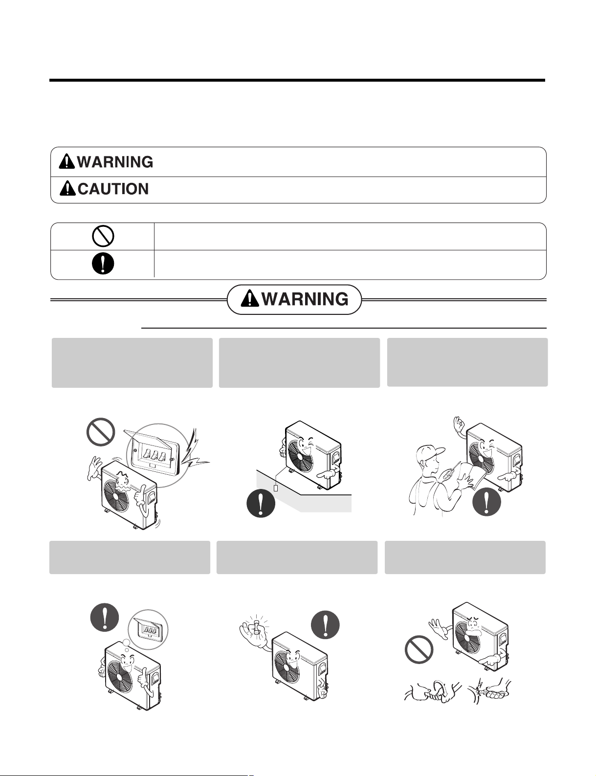
■ Installation
Do not use a defective or
underrated circuit breaker. Use
this appliance on a dedicated
circuit.
• There is risk of fire or electric
shock.
Always install a dedicated
circuit and breaker.
• Improper wiring or installation may
cause fire or electric shock
Always ground the product.
• There is risk of fire or electric
shock.
Use the correctly rated
breaker or fuse.
• There is risk of fire or electric
shock.
Install the panel and the cover
of control box securely.
• There is risk of fire or electric
shock.
Do not modify or extend the
power cable.
• There is risk of fire or electric
shock.
–3–
Page 4
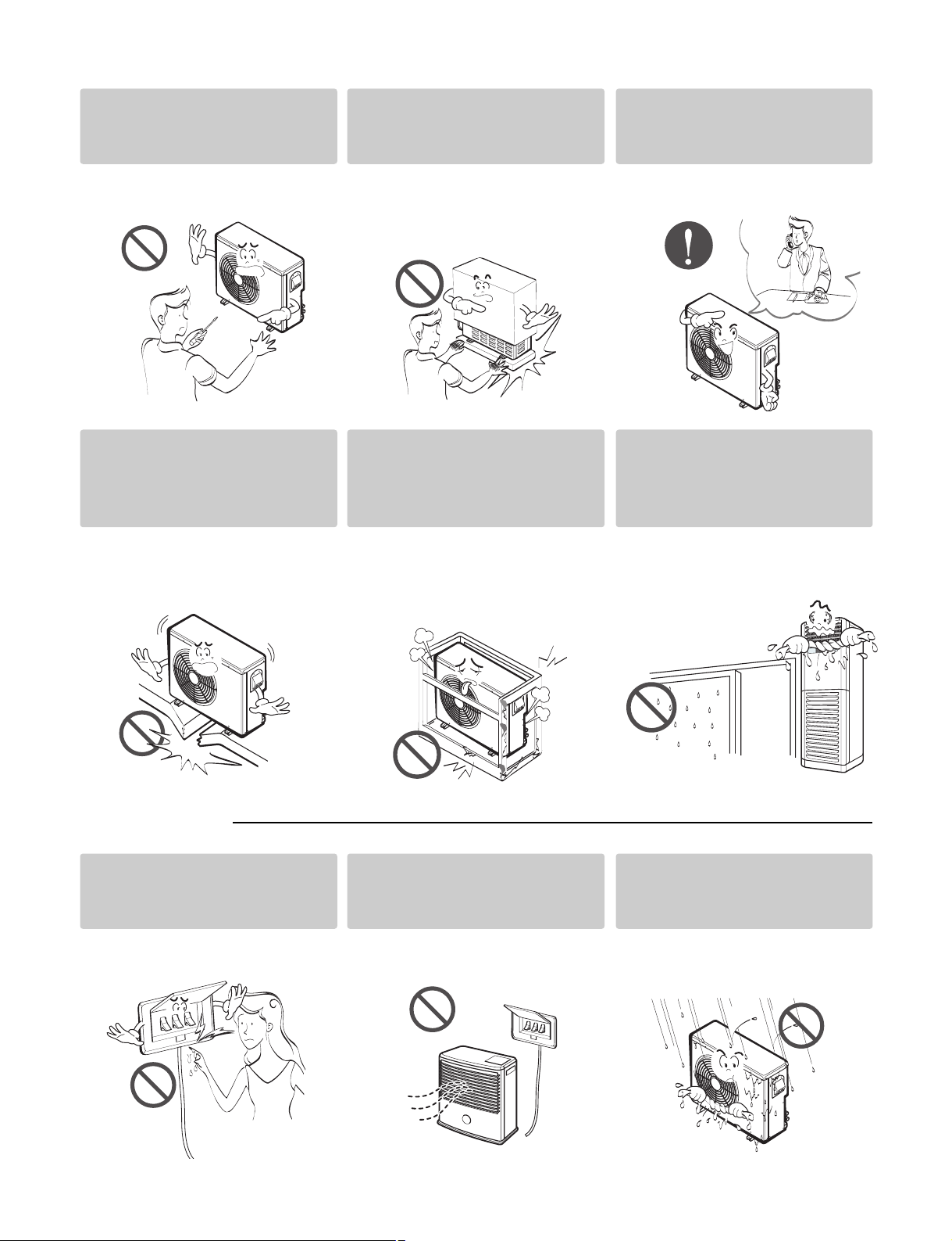
Do not install, remove, or reinstall the unit by yourself
(customer).
Be cautious when unpacking
and installing the product.
For installation, always
contact the dealer or an
Authorized Service Center.
• There is risk of fire, electric shock,
explosion, or injury.
Do not install the product on a
defective installation stand.
• It may cause injury, accident, or
damage to the product.
• Sharp edges could cause injury.
Be especially careful of the case
edges and the fins on the
condenser and evaporator.
Be sure the installation area
does not deteriorate with age.
• If the base collapses, the air
conditioner could fall with it,
causing property damage, product
failure, and personal injury.
• There is risk of fire, electric shock,
explosion, or injury.
Do not let the air conditioner
run for a long time when the
humidity is very high and a
door or a window is left open.
• Moisture may condense and wet or
damage furniture.
■ Operational
Do not touch(operate) the
product with wet hands.
• There is risk of fire or electrical
shock.
Do not place a heater or other
appliances near the power
cable.
• There is risk of fire or electric
shock.
–4–
Do not let electric parts of the
product get wet.
• There is risk of fire, failure of the
product, or electric shock.
Page 5

Do not store or use flammable gas or
combustibles near the product.
If strange sounds, or small or smoke comes
from product. Turn the breaker off or
disconnect the power supply cable.
• There is risk of fire or failure of product.
Gasolin
Do not open the inlet grill of the product during
operation. (Do not touch the electrostatic filter,
if the unit is so equipped.)
• There is risk of physical injury, electric shock, or
product failure.
• There is risk of electric shock or fire.
Be cautious that water could not enter the
product.
• There is risk of fire, electric shock, or product damage.
■ Installation
Always check for gas (refrigerant) leakage after
installation or repair of product.
• Low refrigerant levels may cause failure of product.
Install the drain hose to ensure that water is
drained away properly.
• A bad connection may cause water leakage.
–5–
Page 6
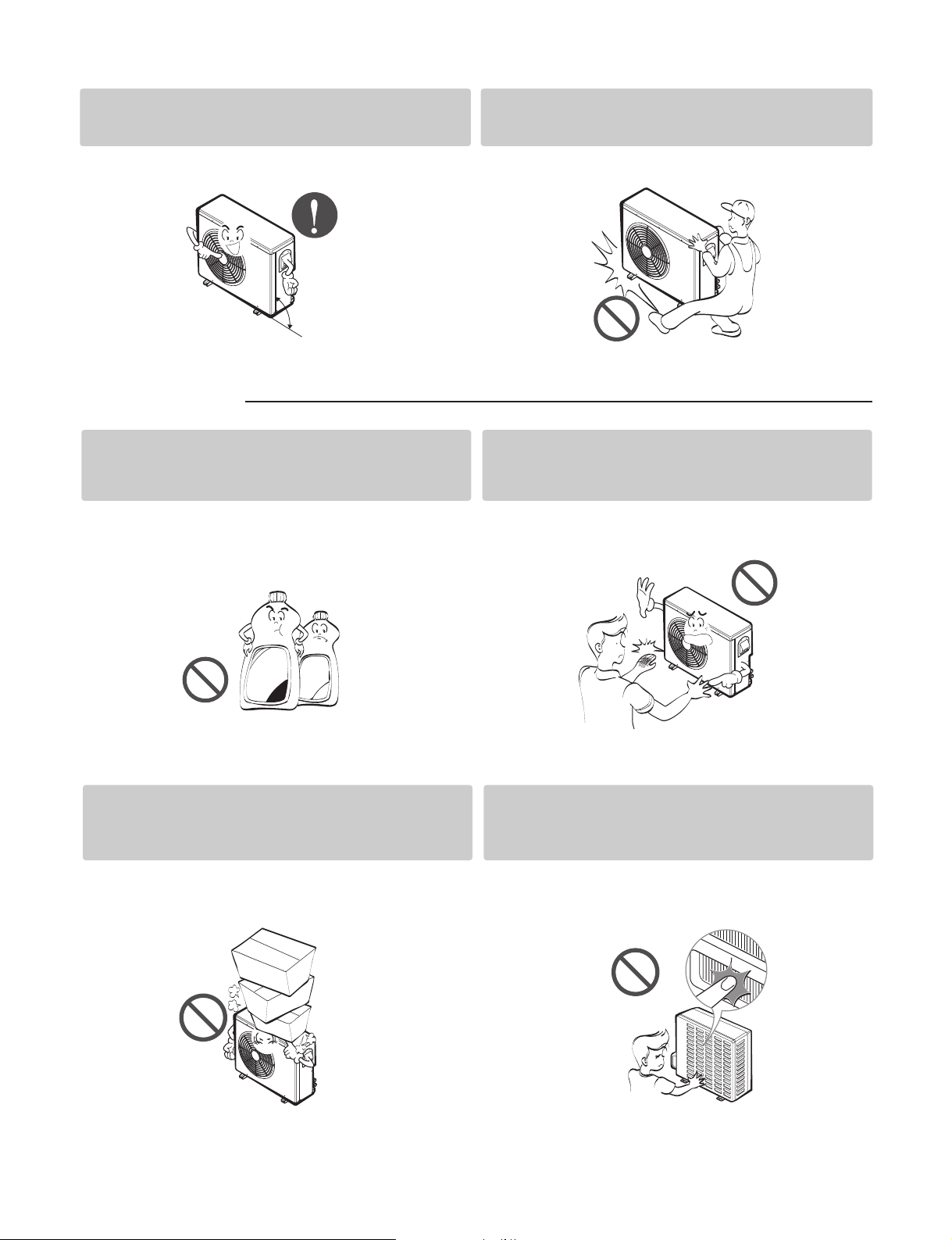
Keep level even when installing the product.
Use two or more people to lift and transport
the product.
• To avoid vibration or water leakage.
90˚
■ Operational
Use a soft cloth to clean. Do not use harsh
detergents, solvents, etc.
• There is risk of fire, electric shock, or damage to the
plastic parts of the product.
• Avoid personal injury.
Do not touch the metal parts of the product
when removing the air filter. They are very
sharp!
• There is risk of personal injury.
Thinner
Wax
Do not step on or put anyting on the product.
(outdoor units)
• There is risk of personal injury and failure of product.
Do not insert hands or other objects through
the air inlet or outlet while the product is
operated.
• There are sharp and moving parts that could cause
personal injury.
–6–
Page 7

Functions
Indoor Unit
Power Switch ON/OFF
Operation Mode Control
• Cooling, Heating, Soft Dry, Fan
Indoor Fan Speed Control
• High, Med & Low
Room Temperature control
• Maintains the room temperature in accordance with the Setting Temp.
• Up: up to 30°C(86.0°F)
• Down: down to 16°C(60.8°F)
Sensing Heat Exchanger Temperature
• Heat exchanger temperature sensor (Thermistor)
Soft Dry Operation Mode
• Intermittent operation of fan at low speed.
Time Delay Safety Control
• Restarting is inhibited for approx. 3 minutes.
AutoRestart
• The power comes on again after a power failure.
–7–
Page 8
Remote Control
Operation ON/OFF
Cooling Operation Mode
Heating Operation Mode
Sot Dry Operation Mode
• Intermittent operation of fan at low speed.
Fan Operation
• Used to circulate room air without cooling.
Timer Control
• OFF Timer (1, 2, 3,......7 hour)
Airflow Direction Control
• Airflow direction Auto-swing and Manual Contol.
Room Temperature Control
• Up: up to 30°C(86.0°F)
• Down: down to 16°C(60.8°F)
Indoor Fan speed control
• High, Med & Low
–8–
Page 9
Outdoor Unit
Deice Control
• De-ice PCB
Outdoor Fan Speed Control
• One speed
Sensing Heat Exchanger Temperature
• Heat exchanger temperature sensor (Thermistor)
(Heating Model Only)
–9–
Page 10
Product Specifications
MODEL
POWER SOURCE (ø, V, Hz)
COOLING CAPACITY BTU/h
INPUT W
CURRENT A
HEATING CAPACITY BTU/h
INPUT W
CURRENT A
MAKER
TYPE
COMPRESSOR MODEL
CAPACITY BTU/h
CURRENT A
INPUT W
NOISE INDOOR
LEVEL(1m) OUTDOOR
W
W
dB(A)
LF300CP(LP-C303R20) LF480CE(LP-C483TA0)
1, 208/230, 60 1, 208/230, 60
28,000 48,000
8,206 14,067
2,600 4,500
11.5 20
--
--
--
--
LG LG
Rotary Rotary
QJ250KAB/QK145KBD QP325KBD * 2
17,658/10,100 24000
7.7/4.5 10.2
1,635/935 2162
50/45/39/32 57/54/51
56 62
AIR INDOOR
VOLUME OUTDOOR
REFRIGERANT R-22
HEAT INDOOR R/C/FPI
EXCHANGER OUTDOOR R/C/FPI
FAN INDOOR
OUTDOOR
ROOM TEMPERATURE CONTROL
NET INDOOR
WEIGHT OUTDOOR
Gross Weight INDOOR kg(lbs)
OUTDOOR
DIMENSIONS INDOOR
(W ¥ H ¥ D) OUTDOOR
SVC LIQUID
VALVE GAS
POWER CABLE P*mm
CONNECTING CABLE P*mm
BREAKER CAPACITY A
CMM
(CFM)
kg(Oz)
TYPE
kg(lbs)
mm
(Inch)
mm
(Inch)
2
2
20/16.5/13/6 (706/583/459/212) 35/33/30(1,236/1,165/1,059)
47 (1,660) 104(3,672)
1.84 (65) 3.92(124.2)
2R/30C/18FPI 3R/28C/18FPI
2R/36C/20FPI 2R/26C/21FPI
TURBO FAN TURBO FAN
Propeller Propeller
Thermistor Thermistor
32(70.5) 58(127.9)
66(145.5) 90(198.4)
38(83.8) 66(145.5)
71(156.5) 100(220.5)
570 x 1,820x 310 (22.45 x 71.7 x 12.2) 590 x 1,810 x 440 (23.23 x 71.26 x 17.32)
870 x 808 x 320 (34.3 x 31.8 x 12.6) 900 x 1,225 x 370 (35.43 x 48.23 x 14.57)
9.52(3/8) 9.52(3/8)
15.88(5/8) 19.05(3/4)
3x4.0 3x5.5
4x1.0 4x1.0
30 40
–10–
Page 11
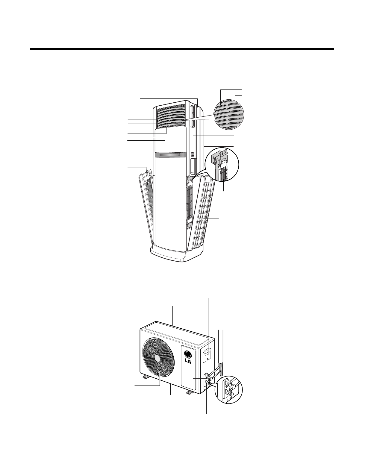
Cool air outlet(2 sides) by
Manual operation
Cool air outlet(front side)
Top/Bottom Airflow Controller
Left/Right Airflow Controller
Sliding Clean Door
Display Panel
Antibiotic Filter
Air Inlet
Air Inlet
Antibiotic Filter
Plasma Deodorant Air Cleaner
Remote Controller Holder
Control Panel
Top/Bottom Airflow Controller
Left/Right Airflow Controller
Air Outlet
Bottom Panel
Ground Terminal
Refrigerant Pipe Port
Air Inlet(back side)
Control Cover
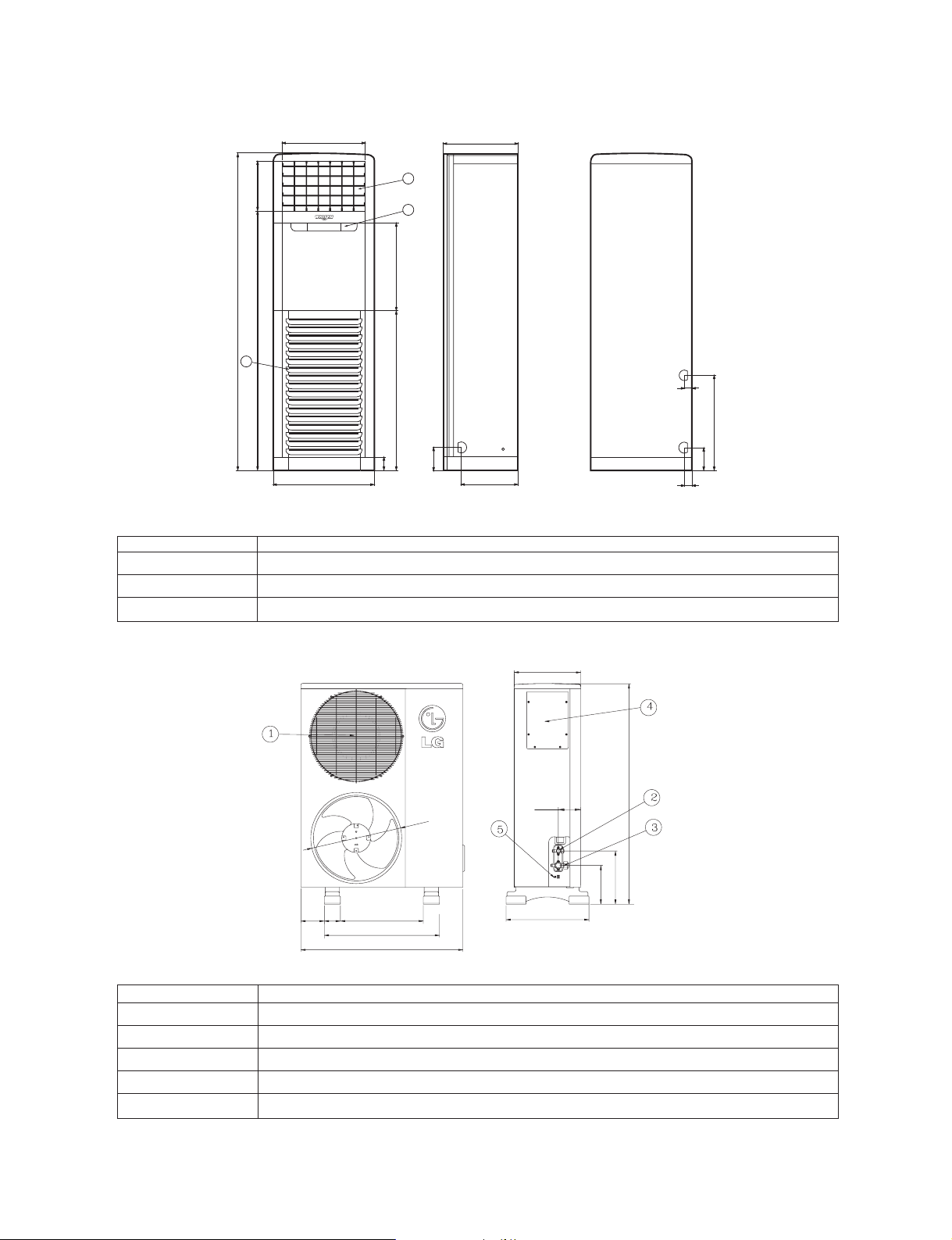
Dimensions
Indoor Unit: LPNC303R20 (LF300CP)
Outdoor Unit : LPUC303R20 (LF300CP)
–11–
Page 12
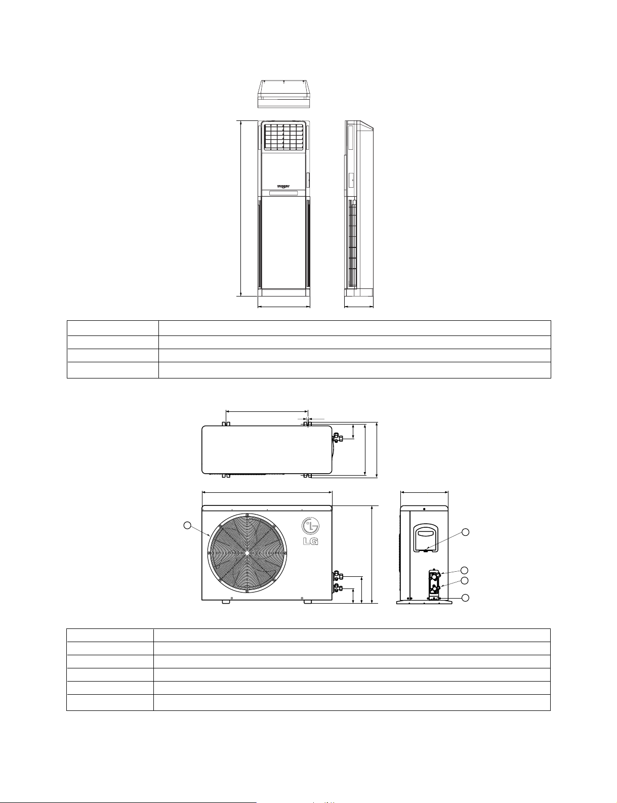
Indoor Unit
800mm(31.5inch)
180mm(7.1inch)
101mm(4.0inch)
370mm(14.6)
340mm(13.4inch)
95mm
870mm(34.3inch)
320mm(12.6inch)
546mm(21.5inch)
5
3
1
2
4
1820mm(71.7inch)
570mm(22.4inch)
311mm(12.2inch)
180mm(7.1inch)
101mm(4.0inch)
No. Items
1 Control Display
2 Air outlet vent
3 Air inlet vent
Outdoor Unit
No. Items
1 Gas side service valve (Ø 15.88mm(5/8inch))
2 Liquid side service valve (Ø 9.52mm(3/8inch))
3 Fan cover
4 Earth screw
5 Connecting cable hole
–12–
Page 13

Air Intake Vent
(Rear)
Air Outlet
Vent
Piping
Air Outlet Vent
Remote Signal
Receptor
Air Intake Vent
Indoor Unit : LPNC483TA0 (LF480CE)
door Unit : LPUC483TA0 (LF480CE)
–13–
Page 14
Indoor Unit
210mm(8.3inch)
290mm(11.4inch)
505mm(19.9inch)
130mm(5.1inch)
41mm(1.6inch)
40mm(1.6inch)
139mm(15.5inch)
260mm(10.2inch)
486mm(19.1inch)
260mm(10.2inch)
260mm(10.2inch)
1850mm(72.8inch)
1540mm(60.6inch)
2
590mm(23.2inch)
525mm(20.7inch)
79mm(3.1inch)
No.
1A
2 Air Inlet Vent
3
439mm(17.3inch)
1
3
950mm(37.4inch)
134mm(5.3inch)
338mm(13.3inch)
Items
ir Outlet Vent
Control display
40mm(1.6inch)
40mm(1.6inch)
562mm(22.1inch)
139mm(15.5inch)
41mm(1.6inch)
41mm(1.6inch)
Outdoor Unit
No. Items
1A
2 Liquid Side SVC Valve(Ø
3 Gas Side SVC Valve(Ø
4 Control Box
5
130mm(5.1inch)
130mm(5.1inch)
90mm(3.5inch)
505mm(19.9inch)
460mm(18.1inch)
640mm(25.2inch)
900mm(35.4inch)
370mm(14.6inch)
125mm(4.9inch)
460mm(18.1inch)
ir Outlet Vent
Earth Screw
1220mm(48.0inch)
290mm(11.4inch)
290mm(11.4inch)
210mm(8.3inch)
210mm(8.3inch)
9.52mm(3/8inch))
19.05mm(3/4inch))
–14–
Page 15
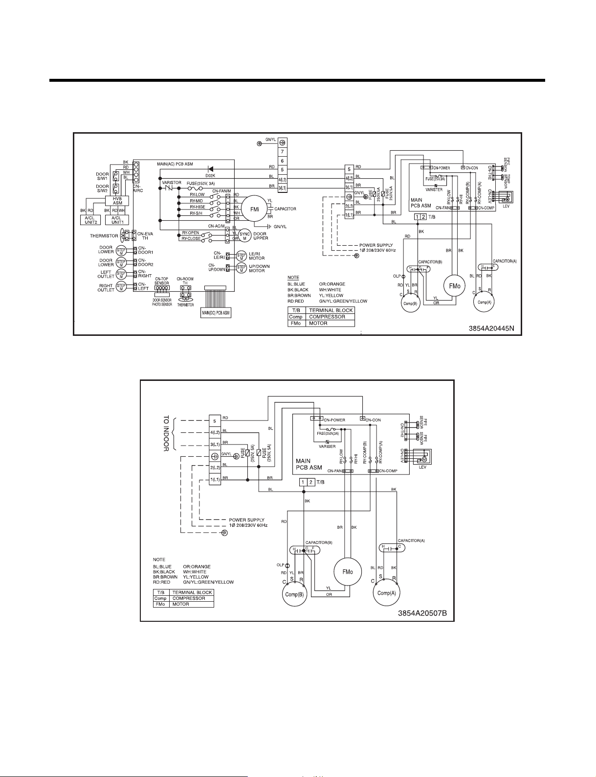
Wiring Diagram
1. LF300CP(LP-C303R20)
Outdoor
–15–
Page 16

2. LF480CE(LP-C483TA0)
Outdoor
–16–
Page 17

Intake Air temp.
Setting Temp. +1°C(1.8°F)
(Compressor ON)
Setting Temp. -1°C(1.8°F)
(Compressor OFF)
Indoor Fan Speed
Selecting
fan speed
Selecting
fan speed
Selecting
fan speed
Selecting
fan speed
Selecting
fan speed
3 minutes
More than
3 minutes
More than
Compressor ON OFF ON OFF ON
Operation Details
....
1. Time Delay Safety Control
3min The compressor is ceased for 3 minutes to balance the pressure in the refrigeration cycle.
(Protection of compressor)
3sec The indoor fan is ceased for 3 seconds to prevent relay noise.
(Protection of fan relay and micro chip)
30sec The 4-way valve is ceased for 30 sec. to prevent the refrigerant-gas abnormal noise when the Heating
operation is OFF or switched to the other operation mode.
2. Airflow Direction Control
This function is to swing the louver left and right automatically and to set it at the desired position.
The procedure is as the following.
1st : Press the ON/OFF Button to operate the product.
2nd : Press the Airflow Direction Control Button to swing the louver left and right automatically.
(Remote controller)
3rd : Repress the Airflow Direction Control Button to set the louver as the desired position.
(Remote controller)
3. Cooling Mode Operation
When selecting the Cooling( ) Mode Operation, the unit will operate according to the setting by the
controller and the operation diagram is as following.
4. Off Timer Function
This function is to set the time of stopping the unit operation.
The procedure is as the following.
1st: Press the timer set button on the Remocon.
2nd: The buzzer sounds and then the display window shows the Off-Time to be set as
- The Off-Time is shifted as the following by each press.
- If you select ' ', the Off-Timer function will be cancelled.
- During Off-Timer Operation, if you repress the timer set button, the rest time will be displayed.
–17–
Page 18

5. Heating Mode Operation
Intake Air Temp.
Setting Temp.
(Compressor ON)
Setting Temp. -1°C(1.8°F)
Indoor Fan Speed
Compressor
ON OFF ON OFF
OFF
Hot
Start
minimum
10sec.
minimum
10sec.
minimum
10sec.
minimum
10sec.
OFF
AA
OFFLOW LOW
Setting Temp. +1°C(1.8°F)
(Compressor OFF)
Selecting
fan speed
Selecting
fan speed
Low(V)Stop(VI)
39°C(102.2°F)
Discharge Air Temp.
Indoor Pipe Temp.
34°C(93.2°F)
28°C(82.4°F)
26°C(78.8°F)
Selecting Fan Speed(IV)
Low(II)Stop(I)
(Hot-Start Operating)
Heating Start
(Hot-Start Release Point)
Selecting Fan Speed(III)
The unit will operate according to the setting by the remote controller and the operation diagram is shown as
following.
• A point: The indoor pipe temperature to be less then 35°C(95.0°F) & Discharge air Temperature to be less than 29°C(84.2°F).
The indoor fan operates for minimum 10sec. even if falls lower than 34°C(93.2°F).
During heating operation, the operating procedure of the indoor fan is as the following.
Step Indoor fan speed Pipe temp. Air discharge temp.
Off
Low 28 C(82.4°F) < 39°C(102.2°F)
Selecting speed 28 C(82.4°F) ≥ 39°C(102.2°F)
Selecting speed 28 C(82.4°F) > 34°C(93.2°F)
Low 26 C(78.8°F) ≤ 34°C(93.2°F)
Off 26 C(78.8°F)
28 C(82.4°F)(Hot start operating)
–18–
Page 19

6. Hot-Start Control
INDOOR PIPE
TEMP.
INDOOR FAN
SPEED
Selecting
fan speed
OFF OFFLOW
1min
Maximum
COMPRESSOR ON
28°C(82.4°F)
26°C(78.8°F)
More than 45 minutes of
heating operation
Outdoor Pipe Temp.
Indoor Fan
Compressor
4-Way Valve
ON
ON
ON
ON
OFF
ON
OFF
HOT-
START
ON
ON OFF OFFON
12°C(53.6°F)
(Defrost OFF)
-6°C(21.2°F)
(Defrost ON)
Within
10 minutes
Defrost
Defrost
More than 45 minutes of
heating operation
• The indoor fan stops until the evaporator piping temperature will be reached to 28°C(82.4°F).
• During heating operation, if piping temperatures fall below 26°C(78.8°F) fan stops.
• The operation diagram is as following.
7. Defrost Control
• Defrost operation is controlled by timer and sensing temperature of outdoor pipe.
• The first defrost starts only when the outdoor pipe temperature falls below -6°C(21.2°F) after 45 minutes passed
from starting of heating operation and more than.
• Defrost ends after 10 minutes pass from starting of defrost operation or when the outdoor pipe temperature rises
over 12°C(53.6°F) even if before 10 minutes.
• The second defrost starts only when the outdoor pipe temperature falls below -6°C(21.2°F) after 45 minutes pass
from ending of the first defrost and more than.
–19–
Page 20

8. Soft Dry Operation Mode
Intake Air Temp.
Indoor Fan Speed
LOW
Selecting
fan speed
Selecting
fan speed
LOW LOW LOW LOW
Compressor OFFON ONON OFF OFF ON
LOW
OFF
Setting Temp.
+2°C(3.6°F)
(Compressor ON)
Setting Temp.
-1°C(1.8°F)
(Compresso OFF)
Operation
Cooling
Cooling
operation
Dry operation
3 min. 3 min.
10 min.
maximum
7 min.
maximum
10 min.
• During Soft Dry Operation, the compressor ON temperature is the setting temperature plus 2°C(3.6°F), the
compressor OFF temperature is the setting temperature minus 1°C(1.8°F).
• When the room temperature rises over the compressor ON temperature, the operation mode is switched to the
Cooling mode.
• When the room temperature falls between the compressor ON temperature and OFF temperature, the operation
mode is switched to the Soft Dry Operation.
• The operation diagram is shown below.
9. Protection of the evaporator pipe from frosting
• Compressor and outdoor fan stop when indoor pipe temperature is below -2°C(28.4°F) and restart at the pipe
temperature is above 12°C(53.6°F).
10. Air Purifying Operation(AP-Z286RC0, AP-Z286R20, AP-Z488TC0)
Mode Selecting
Initial Starting of
Air purifying
Operation
When switched to
Air purifying
operation
11. Child Lock function
This function is to operate Air conditioner only by Remocon.
The procedure is as the following
1st: Press the 2 buttons of the temperature control simultaneously, to raise-to lower on the Display Panel of the
product for more 3 seconds.
2nd: The buzzer sounds and then the window of Display Panel shows CL (CL) mark.
3rd: To release this function, the reverse again the operating procedure could be done.
❈ During this function is operating, any buttons of Display Panel don't work. But it is possible to operate with
Remote controller.
Operating Mode
- Outdoor not operating
- Fan operating + Air
purifying operating
- Outdoor operating
- Main Operating +
Air purifying operating
- Low at the initial
- But could be
Selecting Speed of
Main Operating Mode
Fan Speed
switched to Med. Hi
Outdoor OFF
OFF
ON or OFF
depend on main
operating
condition.
Repress Air
purifying
Button or
ON/OFF
Button
–20–
Page 21

12. Alarm mode display / only displayed while operating.
Setting energy
saving operation
Setting temp.
23°C(73.4°F)
21°C(69.8°F)
22°C(71.6°F)
23°C(73.4°F)
24°C(75.2°F)
25˚C(77.0°F)
26°C(78.8°F)
27°C(80.6°F)
Setting temp.
24°C(75.2°F)
Setting temp.
25°C(77.0°F)
maintains setting temp.
25°C(77.0°F)
28min.
50min. 50min. 50min.
35min. 47min.
CO : The sensor for sensing room temperature is open or short.
C1 : The sensor for sensing piping temperature is open or short.
13. Energy Saving
➀ If setting temperature of starting energy saving operation is under 22°C(71.6°F), first, setting temperature it
up to 22°C(71.6°F) and perform energy saving operation.
➁ After energy saving operation starts, if adaptation time of the human body pass from the point which room
temperature and setting temperature meet together, increase setting temperature 1°C(1.8°F) more.
➂ If it doesn't satisfy number ➀ even in 50 minutes from the start of energy saving operation, increase
1°C(1.8°F).
➃ After increasing setting temperature 1°C(1.8°F) more by number ➀, ➁, perform number ➁, ➂ again, if setting
temperature goes up to 25°C(77.0°F), maintain this temperature.
➄ If setting temperature goes down to under 25°C(77.0°F), during the operation, do number ➁, ➂, ➃ again.
14. AUTO RESTART
In case the power comes on again after a power failure, Auto Restarting Operation is the function to operate
procedures automatically to the previous operating conditions.
15. Function of changing set temperature when re-operation after stop.
Operation is set the following condition when re-operation with start/stop button.
1.Operation mode.
Cooling/soft dry mode
Heating mode Heating mode
2. Setting the set temperature when cooling operation.
Room temperature > Set temperature: to be set to the previous set temperature.
Room temperature ≤ Set temperature
a) Room temperature ≥ 26°C(78.8°F): to be set to 24°C(75.2°F)
b) 22°C(71.6°F) ≤ Room temperature ≤ 25°C(77.0°F): to be set to 21°C(69.8°F)
c) 19°C(66.2°F) ≤ Room temperature ≤ 21°C(69.8°F): to be set to -1°C(1.8°F) less than room temperature.
d) Room temperature ≤ 18°C(64.4°F): to be set to 18°C(64.4°F)
Cooling mode
–21–
Page 22

3. Setting the set temperature when heating operation.
Room temperature < Set temperature: to be set to the previous set temperature.
Room temperature ≥ Set temperature
a) Room temperature ≤ 20°C(68.0°F)(: to be set to 23°C(73.4°F)
b) 21°C(69.8°F) ≤ Room temperature ≤ 25°C(77.0°F): to be set to 26°C(78.8°F)
c) 26°C(78.8°F) ≤ Room temperature ≤ 28°C: to be set to +1°C more than room temperature.
d) 29°C(84.2°F) ≤ Room temperature : to be set to 30°C(86.0°F)
16. Function for test operation
1) Outline of Operation
- This is for checking the condition of installation during the installation, and it is operated by cooling, Fan speed
is high, comp. on, and Auto air flow operations without setting temperature.
2) Operation or Cancel
- Do test operation, if you push ON/OFF button and the down room temperature checking button over 3
seconds at the same time.
- During the operation, if you push the stop button or push ON/OFF button and the down room temperature
checking button over 3 seconds at the same time, the test operation will be cancelled and unit come to rest.
- During the operation, if you input remocon key or key on Display panel, it performs its duties.
3) Function
- It operates cooling, fan speed is high, auto air flow operation, comp. on for 18 ± 1 minutes, regardless of room
temperature.
- After 18 ± 1 minutes of operation, it becomes off itself.
- During the operation, signal 88 stands for "Lo"
–22–
Page 23

Installation of Indoor, Outdoor Unit
A
B
Indoor unit
Outdoor unit
50mm(2inch)
1000mm(39.4inch)
Indoor unit
500mm(20inch)
500mm(20inch)
500mm (20inch)
1000mm(39.4inch)
400mm
(16inch)
400mm
(16inch)
500mm(20inch)
1. Selection of the best location
1) Indoor unit
• There should not be any heat source or steam
near the unit.
• There should not be any obstacles to prevent the
air circulation.
• A place where air circulation in the room will be
good.
• A place where drainage can be easily obtained.
• A place where noise prevention is taken into
consideration.
• Do not install the unit near the door way.
• Ensure the spaces indicated by arrows from the
wall, ceiling, fence, or other obstacles.
2) Outdoor unit
• If an awning is built over the unit to prevent direct
sunlight or rain exposure, be careful that heat
radiation from the condenser is not restricted.
• There should not be any animals or plants which
could be affected by discharged hot air.
• Ensure the space indicated by arrows from the
wall, ceiling, fence, or other obstacles.
3) Piping length and the elevation
Cooling Only Model
MODEL
(BTU/h)
48k 3/4" 3/8" 40/131 25/82
GAS SIDE LIQUID SIDE
PIPE SIZE
Max.
Length
A (m/ft)
Max.
Elevation
B (m/ft)
30k 5/8" 3/8" 30/98 20/66
–23–
Page 24

2. Indoor Unit installation
Wall
Core Drill
Tilt
Cut if necessary
More than 15mm(0.6 inch)
Wall
Plastic tube
(Bushing)
INSIDE OUTSIDE
200mm(7.9 inch)
70mm(2.8 inch)
70mm(2.8 inch)
90mm(3.5 inch)
The mounting floor should be strong and solid
enough to prevent it from vibration.
Drill the piping hole with 2.8 inch diameter holecore drill at either the right or the left of indoor
unit. The hole should be sightly slant to the
outdoor side.
3. Outdoor unit Installation
Install the outdoor unit on the concrete or any
solid base securely and horizontally by securing
it with bolts (Ø12mm(0.5inch)) and nuts.
If there is any vibration transmitted to the
building, mount the rubber underneath the
outdoor unit.
4. Refrigerant amount
Before shipment, this air conditioner is filled with
the rated amount of refrigerant including additional
amount required for air-purging, subject to
7.5m(25ft) piping length. (The rated amount of
refrigerant is indicated on the name plate.) But
when the piping length exceeds 7.5m(25ft),
additional charge is required according to the
following table.
MODEL (BTU/h) REFRIGERANT CHARGE
48k 40g/m(1.41oz/m)
30k 30g/m(1.06oz/m)
Example)
In case of 15m(49ft) long pipe(one-way), the
amount of refrigerant to be replenished is:
48k : (15-7.5) x 40 = 300g
(15-7.5) x 1.41 = 10.58oz
Insert the plastic tube through the hole.
Cut the extruded outside part of the plastic tube,
if necessary.
–24–
Page 25

Test running
1. PRECAUTIONS IN TEST RUN
• The initial power supply must provide at least 90% of the rated voltage.
Otherwise, the air conditioner should not be operated.
Caution
• The test run is started by pressing the down room temperature checking button and ON/OFF button for 3
seconds at the same time.
• To cancel the test run, press ON/OFF button.
CHECK THE FOLLOWING ITEMS WHEN INSTALLATION IS COMPLETE
• After completing work, be sure to measure and record trial run properties, and store measured data, etc.
• Measuring items are room temperature, outside temperature, suction temperature, blow out temperature, wind
velocity, wind volume, voltage, current, presence of abnormal vibration and noise, operating pressure, piping
temperature, compressive pressure.
• As to the structure and appearance, check following items.
Carry out the test run more than 5 minutes without fail.
(Test run will be cancelled 18 minutes later automatically)
Is the circulation of air adequate?
Is the draining smooth?
Is the heat insulation complete
(refrigerant and drain piping)?
Is there any leakage of refrigerant?
Is the remote controller switch operated?
Is there any faulty wiring?
Are not terminal screws loosened?
M4...118N cm{12kgf.cm}
0.8 lbf.ft(10 lbf.in)
M6...245N cm{25kgf.cm}
1.8 lbf.ft(22 lbf.in)
M5...196N cm{20kgf.cm}
1.4 lbf.ft(17 lbf.in)
M8...588N cm{60kgf.cm}
4.3 lbf.ft(52 lbf.in)
2. Connection of power supply
1. Connect the power supply cord to the independent power supply.
• Circuit breaker is required.
2. Operate the unit for fifteen minutes or more.
3. Evaluation of the performance
1. Measure the temperature of the intake and discharge air.
2. Ensure the difference between the intake temperature and the discharge one is more than 8°C(46.4°F)
(Cooling) or reversely (Heating).
–25–
Page 26

CAUTION
After the confirmation of the above conditions, prepare the wiring as follows:
1) Never fail to have an individual power specialized for the air conditioner. As for the method of wiring,
be guided by the circuit diagram pasted on the inside of control box cover.
2) Provide a circuit breaker switch between power source and the unit.
3) The screw which fasten the wiring in the casing of electrical fittings are liable to come loose from
vibrations to which the unit is subjected during the course of transportation. Check them and
make sure that they are all tightly fastened. (If they are loose, it could give rise to burn-out of the
wires.)
4) Specification of power source
5) Confirm that electrical capacity is sufficient.
6) Be sure that the starting voltage is maintained at more than 90 percent of the rated voltage marked
on the name plate.
7) Confirm that the cable thickness is as specified in the power sources specification.
(Particularly note the relation between cable length and thickness.)
8) Never fail to equip a leakage breaker where it is wet or moist.
9) The following troubles would be caused by voltage drop-down.
• Vibration of a magnetic switch, damage on the contact point there of, fuse breaking, disturbance to the
normal function of a overload protection device.
• Proper starting power is not given to the compressor.
HAND OVER
Teach the customer the operation and maintenance procedures, using the operation manual (air filter cleaning,
temperature control, etc.).
If Error Code happens in the display of indoor.
Error Code Error Contents Checking Point
C0
C1
C3
C4
C5
Indoor Air Sensor Open or Short
Indoor Pipe Sensor Open or Short
Outdoor Air Sensor Open or Short
Outdoor Pipe Sensor Open or Short
Communication failure between
Indoor and outdoor unit.
1.Check Sensor Connection to PCB whether it's
connected well or not.
2.Replace it with new Sensor.
1.Check connecting cable wiring order between
Indoor and outdoor diagram.
2.Check all wire connector whether it is connected
or not.
3.Indoor AC PCB defects.(short inside).
4.Outdoor PCB defects.(short inside)
–26–
Page 27

Troubleshooting Guide
Failures to Start
Check of circuit breaker
and fuse.
Check control switch.
Fan only fails to start
Improper wiring
Defect of fan motor
capacitor.
Irregular motor
resistance
( Ω )
Irregular motor
insulation
( Ω )
Replacement of fan motor.
Improper electric heater
Replacement of electric
heater
Regular but fails to start.
Replacement of compressor
Electric heater is not energized
Loose terminal connection.
Improper wiring
Irregular motor resistance ( Ω
)
Irregular motor insulation ( Ω
)
Replacement of compressor
Drop of power voltage
Capacitor check
Replacement
Compressor only fails to
start
Defect of compressor
capacitor
Check power source.
Check control switch
setting.
–27–
Page 28

PACKAGE AIR CONDITIONER VOLTAGE LIMITS
NAME PLATE RATING MINIMUM MAXIMUM
380 V 342 V 418 V
220 V 198 V 242 V
380 - 415 V 342 V 456 V
No cooling and heating operation performed
WHAT TROUBLED COMPLAINTS HOW TO CHECK REMEDY
Other parts than the unit
Magnetic switch for
compressor & fan motor
Operating switch
Protection devices
Electric supply interrupted
Defective power wiring Cut
of power fuse
Too low voltage
Control point is on
condition of "OFF" due to
trouble.
Troubled or defective
contactor
Opened the contact point
with trouble
Measure it with a tester in
case that the same
power source is supplied
to other equipment than
the unit, what and where
trouble can be discovered
by checking the operation
of other equipment.
Measure it with a tester.
Make short-circuit, then
measure it with a tester.
Check it with the eyes or
tester.
Check it with the eyes or
tester.
Repair a switch box and
is relative instrument.
Replacement of fuse
Request a power
supplier to repair.
Check the power source.
Use a thick cable if
necessary.
Replace it if necessary.
Repair or replace it.
Discover the trouble
cause and push the rest
button.
2) Only blowers do not work
WHAT TROUBLED COMPLAINTS HOW TO CHECK REMEDY
Air volume change over
switch
Capacitor
Troubled or defective
contact point
Defected
Check it with the eyes or a
tester
Check it with a tester.
–28–
Repair or replace it.
Replace it.
Page 29

3) Only outdoor fan does not work
WHAT TROUBLED COMPLAINTS HOW TO CHECK REMEDY
Motor
Electric Wiring
Over-heated
Layer short
Open wire on operation
Short circuited on
operation
Check how it is insulated.
Check it with a tester.
Repair or replace it.
Rewiring or repair.
4) Only compressor does not work
WHAT TROUBLED COMPLAINTS HOW TO CHECK REMEDY
Magnetic switch for
compressor motor
Compressor motor
Compressor
High pressure switch
Defective contact,
magnetic coil troubled.
Troubled over-heated
(layer short)
Troubled or over-heated
(lock)
Troubled or defective
contact or operating
Check it with the eyes on
with a tester.
Check how it is insulated.
Groaned noise of motor
Check it with a tester.
Repair or replace it.
Replace or repair the
compressor.
Repair or replace it.
Replace it if necessary.
Electric circuit
Defective connection or
disconnection of the circuit
for compressor.
Check it with a tester.
Rewiring or push reset
button.
–29–
Page 30

The Units discontinue after the operation started
WHAT TROUBLED COMPLAINTS HOW TO CHECK REMEDY
Other parts than the unit
Outdoor coil
In-condensable gas
blended.
High pressure switch
Improper opening of the
service valves in the
refrigerant line
Coil is dirty *1
Air intruded into the
refrigerant pipe line *1
Improper adjustment
Checking
Checking
In the event that
difference between the
saturating temperature
corresponding to high
pressure and the
temperature of air
discharged from the
outdoor coil is more than
15°C, incondensable gas
may be blended.
Check it with a pressure
gauge.
Open it properly
Wash it by means of
something like chemical
washing.
Extract air by vacuum
pump, then recharge the
refrigerant.
Readjust it to normal
operating pressure.
(Note)
Don't alternate the
specified adjusting
pressure. If the adjusted
pressure exceeds the
specified range, it will
cause a great accident.
Refrigerant
Outdoor Fan
Note: Use an appropriate measuring instrument for readjustment.
*1: Check the High-pressure switch indication.
*2: Check the Low- pressure switch indication.
A shortage of refrigerant
amount. * 2
Reverse rotation of fan
Obstacle
Air short circuit *1
Confirm the wind blowing
out.
Check it with eyes.
–30–
Recharge the
refrigerant. Repair the
spot where it leaks.
If reversed, connect
interchanged wires to
each terminal.
Power wirings.
Page 31

The unit is working, but not cooling and heating sufficiently
(Both blower and compressor are working)
WHAT TROUBLED COMPLAINTS HOW TO CHECK REMEDY
Load
Air flow
Short air volume
Refrigerant
Air passage
Air filter
9.4
All the functions are performed normally, but very noisily and much vibratively.
WHAT TROUBLED COMPLAINTS HOW TO CHECK REMEDY
Much heat load
Obstacle disturbs Intake
of uniform wind.
Reverse rotation of
blower.
Shortage in the charged
refrigerant.
Improper or foreign bodies
Clogged with dust
Heat load increased.
Window or door has many
cracks or gaps.
Checking
Checking
Coil inlet pipe is frosted
Checking
Checking
Do necessary disposal
respectively.
Correct it.
Correct it.
Replenish it.
(Repair the leakage spot).
Correct or clear the
foreign bodies.
Cleaning
Compressor
Blower
Screws
Liquid refrigerant flooding
back from the evaporator.
Compressor shipping
bracket is not removed.
Faulty discharge valve and
suction valve.
Fan broken.
Other materials intruded.
Looseness or fail-off of
screws
• Check for refrigerant over-charge.
• Check to see if the intaking air temperature is
extremely cold.
• Check for insufficient air flow quantity.
• Checking
• Checking
Checking
Checking
• Remove the shipping
bracket.
• Replace the
compressor
• Repair or replace it.
• Clear the other
material
Repair
–31–
Page 32

WHAT TROUBLED COMPLAINTS HOW TO CHECK REMEDY
Electric troubles
(Magnetic
contactor)
Others
Defective contact.
Defective contact point.
Rusting and faults in the iron
core contact face. Defective
contact of the
operating switch.
Improper installation
Trouble checking by protection devices
Fault Cause Check/Correcitve Action
High Discharge
Condenser cooling air extremely hot or
insufficient air flow through the condenser
Inside of the condenser tube is clogged.
Air in the refrigeration cooling cycle.
Suction pressure is higher than standard.
Checking
Checking
Repair and clean or
replace it.
Correct it.
1. Check the operation of the outdoor motor.
2. Check discharge and suction, air
circulation.
Clean condenser coil.
Purge air from the cycle.
See "High Suction Pressure".
Low
Discharge
High
Suction
Pressure
Low
Suction
Pressure
Faulty discharge valves or suction valves of
the compressor.
Refrigerant low-charge or leakage.
Suction pressure is lower than standard.
Intake air extemely hot or excessive air flow
through the evaporator coil.
Refrigerant over-charge.
Faulty discharge valve or suction valve of
the compressor.
Discharge pressure is higher than standard
Intake air extremely cold or insufficient air
flow through the evaporator coil.
Refrigerant short-charge or leakage.
1. Check unit operation input
2. Check the suction pressure.
Add refrigerant: repair leakage if any.
See "Low Suction Pressure".
1. Check fresh air, intake or check for
leakage of the return air.
2. Check air flow quantity.
Purge the refrigerant.
Check the operating input.
See "High discharge Pressure".
1. Check air flow quantity.
2. Check air filter.
3. Check evaporator coil frosting
Add refrigerant, repair leakage, if any.
Restricted liquid in the suction line.
–32–
Check the capillary tube and the strainer.
Page 33

Fault Cause Check/Correcitve Action
Internal
Thermostat
Cut-Off
Overcurrent
Relay for
Compressor
Cut-Off
Discharge pressure is lower than standard.
Single or three phases running.
High or low voltage or phase unbalance.
Refrigerant short charge or leakage.
Compressor frequently stops and starts.
Discharge and suction pressure are
extremely high.
High or low voltage, or phase unbalance.
Single or three phases running
Faulty compressor motor.
See "Low Discharge Pressure".
Check the power supply line and the
contactor.
Check the voltage and phase unbalance.
Add refrigerant, repair leakage, if any.
Check thermistor operation, or any other
cause for frequent stop and start operation.
See "High Discharge Pressure" or "High
Suction Pressure".
Check the voltage and phase unbalance.
Check the power supply line and the
contact.
Check electric resistance among the
compressor terminals, and from the
terminals to ground.
Overcurrent
Relay for
Fan Motor
Cut-Off
Fuse Blown
Disconnection
and Faulty
Contact
Loose connections.
Compressor frequently stops and starts.
High or low voltage, or phase unbalance.
Single or three phases running.
Faulty fan motor.
Loose connection.
Faulty fan bearing.
Loose connections.
Single or three phase running.
Faulty motor.
Disconnection.
Faulty contact.
Check the electric connections.
Check the operation of the thermistor, or
any other cause for frequent stop.
Check the voltage and electric wiring.
Check the power supply line and the
contactor.
Check the fan motor and wiring.
Check the elelctric connections.
Check repair or replace the bearing.
Check the electric connections.
Check the power supply line.
Check electric resistance among motor
housing, and from the terminals to
ground.
1. Check the wires and connect where
necessary.
2. Check the contact holding coil.
Check the contact in the magnetic
contact, the over-current relay, the
pressure control switch, the operation
switch, the auxiliary relay.
–33–
Page 34

YES
YES
NO
NO
NO
NO
NO
NO
YES
YES
YES
YES
Electronic Parts Troubleshooting Guide
1) No cooling operation performed.
Is the AC220V
(AC 240 V) between Connector(CN-
outunit) Pin 1 and Pin 3 of
Main P.C.B
ON/OFF S/W ON
Is the unit operating?
Is it Cooling mode?
Room temp, > Set temp?
Is the input power
AC220V (AC240V) at COMP
Magnetic coil?
Check the magnetic
contactor of outdoor unit.
Select the cooling
operation mode.
Check the wiring
diagram.
Is the DC5V at 14
pin of MICOM
Replacement IC02M, RY-COMP
Room temp, >set temp
setting
Replacement MICOM
–34–
Page 35

2-1) Indoor fan does not operate
YES
YES
YES
YES YES YES
YES YES YES
YES
NO
NO
NO
NO
NONONO
NO NO NO
Is the unit
operating?
Is the DC5V
at 20pin of
(MICOM)?
Reset the power ON/OFF S/W
Replacement ICO3M
AC220V(240V) between
Is the DC12V
at each terminal
RY-S/High Coil
Is the
"C" and "S/High" of
P.C.B?
Is the DC5V
at 21pin of
(MICOM)?
Is the DC12V
at each terminal
RY-High Coil
Is the
AC220V(240V) between
"C" and "High" of P.C.B?
Is the DC5V
at 22pin of
(MICOM)?
Is the DC12V
at each terminal
AC220V(240V)
between "C" and "Mid"
RY- Mid Coil
Is the
of P.C.B?
Replacement
(MICOM) and
check the EVA-Th.
Replacement S/High
Check the motor winding
Replacement High Replacement RY-Mid
–35–
Page 36

3) Airflow Direction does not operate.
YES
NO
YES
NO
YES
NO
YES
NO
YES
NO
Is the unit operating?
Is the Auto Swing S/W "ON"?
Is the DC5V at 16 terminal?
(MICOM)
Is the DC12V
at each terminal?
(RY-Sync COIL)
The power ON/OFF S/W ON
Press the Auto Swing S/W
Replacement MICOM
Replacement ICO2M
Is the AC220V(240V)
at each terminal
(SYN. MOTOR CONNECTOR)?
Check the synchronous
motor winding.
Replacement RY-Sync
Check synchronous connector
contact point.
–36–
Page 37

4) Remote control does not operate.
YES
NO
YES
NO
YES
NO
YES
NO
Is the battery of remote
controller normal?
Is the CN-Disp1
connector normal?
Does the operation
of remote controller
properly?
Is the Pre-amp of
display normal?
Replacement battery
Check the connector.
CN-Disp1
Replacement remote-controller
Replacement preamp assy
Replacement MICOM
–37–
Page 38

5) The unit does not operate.
YES
NO
YES
NO
YES
NO
YES
NO
(240V) at Trans input terminal?
Is the AC220V
Is the AC12-18V at
Trans (2nd)?
Is the connector of
Main/Display correct?
Is the DC5V between PIN64
and PIN 32 of MICOM?
1. Check the electric connections
2. Check the fuse of Main PCB ASM
Replacement Trans
Check the connector of
Main/Display
1. Replacement ICO3D
2. Replacement Main PCB ASM
Replacement Main PCB ASM
6) Timer control does not operate.
–38–
Replacement
Micom
Page 39

7) No heating operation works
YES
YES
NO
NO
NO
NO
NO
NO
NO
NO
NO
NO
NO
YES
YES
YES
YES
YES
YES
YES
YES
YES
Is the AC220V
(AC 240 V) between connector
(CN-outunit) Pin 1 and Pin 3 of
Main P.C.B
Is the unit operating?
ON/OFF S/W ON
Is it heating mode?
Is the input power AC220V
(AC240V) at COMP magnetic coil
Check the COMP magnetic
contactor of outdoor unit.
contactor?
Check the wiring
connection
Room temp <Set temp?
Is the DC5V
at 14 pin of Micom terminal
Is the DC5V
at 18 pin of Micom terminal
Is the DC12V
at each terminal?
(RY-4way COIL)
Is the
AC220V (AC 240 V) between
connector(4WAY) and CN-outunit Pin 1 of
Main
P. C . B
Select the heating operation mode.
Room temp. < Set temp. Setting
Replacement MICOM
Replacement MICOM
Replacement ICO2M
Replacement RY-4way
Is the DC12V at
each terminal?
(AC 240 V) between connector(CN-outunit)
Is the AC220V
Pin 1 and Pin 3 of Main
P. C . B
–39–
Replacement ICO2M
Replacement RY-Comp
Page 40

8) No heater operation works
YES
NO
YES
NO
YES
NO
YES
NO
YES
NO
YES
NO
Is the heating operating?
Is the Compressor
operating?
Is the Heat S/W of Main
PCB "ON"?
Is the DC 5V at 15 pin of
DC 12V at eack terminal?
MICOM
Is the
(RY-Heater COIL)
Select the heating operation mode.
Compressor "ON"
Heat S/W "ON"
Replacement MICOM
Replacement ICO2M
Is the
AC220V (AC 240 V) between
connector(HEATER) and CN-outunit Pin 1
of Main P.C.B
Check the heater wiring
Replacement RY-Heater
–40–
Page 41

Exploded View and Replacement Parts List
267110
237201
135313-1
135313-2
235811-2
235811-1
137211
132100
235512
249941
268711-1
249951
159830
W0CZZ
268711-2
1. Indoor Unit
• Model : LF300CP(LP-C303R20)
–41–
Page 42

130911
35211C
354210
W4811-1
567480-3
Eva-out
336610
W4810-1
730700
346810
359012
W1NF
140570
W1WE
349480
567480-1
Inlet-air
159830-1
337000
266000
352150
336600
W4810-2
W4811-2
135515
W52103
35211A
–42–
Page 43

268711-3
268711-1
567480-1
Inlet-air
567480-3
Eva-out
W4810-2
137211
237202
35211A 35211C
152302
135313
330870
146812
W4810-1
354210
552111
W4811
267110
135080-2
135310
146811
135080-1
135080-3
135080-4
• Model : LF480CE(LP-C483TA0)
–43–
Page 44

359012
346810
150170
130400
349480
135317
135500
268711-2
249941
249951
W4810
W0CZZ
336610
135515
130911
349600
–44–
Page 45

2. Outdoor Unit
435512
437210
349480-1
447910
559010
546810
349600
W0CZZ-2
W0CZZ-1
W6920
W5210D
552113
552201
554160-1
554160-2
552200
661400
649950
554030
137213-1
435300
137213-2
435511
552203-1
552203-2
430410
435301
268711-4
548490
567480-4 552112
Air
Accum.
• Model : LF300CP(LP-C303R20)
–45–
Page 46

• Model : LF480CE(LP-C483TA0)
437212
435512
435301
437210
559010
137213
435511
546810
447900
554031
552203-2
552203-1
430411
349600-1
W5210D
554160
552112
552201
552200
661400
552113
649950
W0CZZ-1
268711-4
567480-4
Air
Accum.
548490
–46–
Page 47

P/No.: 3828A20156T
December, 2006
Printed in Korea
 Loading...