

Page 1
Please read this manual carefully.
Retain for future reference.
If you have questions, call 1-800-243-0000
or visit our website at: http://www.lgservice.com
or http://us.lgservice.com
MODEL : LDF7810WW / LDF7810BB / LDF7810ST
LDF7811WW / LDF7811BB / LDF7811ST
LDS5811WW / LDS5811BB / LDS5811ST
LDF6810WW / LDF6810BB / LDF6810ST
Page 2
SS
AAFFEETTYY AANNDD CCAAUUTTIIOONN
2
CC
OONNTTEENNTTSS
PART 1. SAFETY AND CAUTION ............................................................................................... 2
PART 2
. DISHWASHER SPECIFICATIONS ................................................................................. 3
PART 3
. TOOLS AND MATERIALS NEEDED ............................................................................. 4
PART 4. INSTALLATION INSTRUCTIONS ............................................................................ 5~11
SAFETY AND CAUTIONS
• Disconnect electrical power before you start !
• All electrical wiring and grounding should be done in accordance with national and local
codes.
• If electrical supply is damaged, it must only be replaced by the manufacturer or its service
agent or a similar qualified person in order to avoid a hazard.
• This dishwasher must be connected to a hot water supply between 120℉(49℃)~149℉(65℃).
This temperature range provides the best washing results and shortest cycle time.
Temperature should not exceed 149℉(65℃) to prevent damage to dishes.
• This appliance must be positioned close to an electrical power supply.
• The appliance is to be connected to the water supply using new hoses. Old hoses should not
be reused.
GROUNDING INSTRUCTIONS
• For a permanently connected dishwasher:
This appliance must be connected to a grounded metal, permanent wiring system, or an
equipment-grounding conductor must be run with the circuit conductors and connected to the
equipment-grounding terminal or lead on the appliance.
WARNING!
When installing and using your dishwasher, follow basic precautions, including the
following:
!
IMPORTANT SAFETY INSTRUCTIONS
Page 3
3
DD
IISSHHWWAASSHHEERR SSPPEECCIIFFIICCAATTIIOONNSS
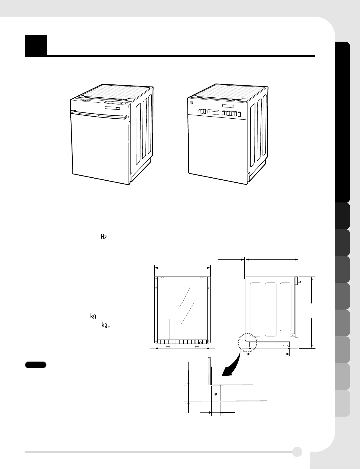
DISHWASHER SPECIFICATIONS
Product Dimension
■ Power supply: 120V, 60 AC only
■ Water Pressure: 20 - 120 psi
(140 - 830 kPa)
■ Size: Fully / Semi (WXDXH):
23 7/8
″″
X 24 5/8″″X 33 7/8
″″
(606mm X 625mm X 860mm)
■ Inlet Water Temperature:
120
°F (49℃)
■ Weight: 115 Ibs. (52 , Fully-
Integrated), 110 Ibs. (50
Semi-
Integrated)
Specifications are subject to change
to improve performance.
Water supply hose, Drain hose
and Electric Cable
Should be passed through by this area
Felt
(insulating
material)
may be
compressed
33-7/8″
(860mm)
20-3/8″(518mm)
6-3/4″
(171mm)
3″(76mm)
23-7/8″(606mm)
24-5/8″(625mm)1/5″(5mm)
Fully Integrated
LDF7810WW/BB/ST
LDF7811WW/BB/ST
LDF6810WW/BB/ST
Semi Integrated
LDS5811WW/BB/ST
NOTE The features on your dishwasher
may vary from the figure shown.
Page 4
4
TT
OOOOLLSS AANNDD MMAATTEERRIIAALLSS NNEEEEDDEEDD
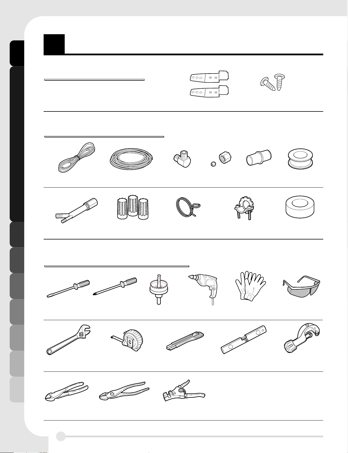
TOOLS AND MATERIALS NEEDED
INSTALL BRACKET WOOD SCREW
OO
OOTTTT
HH
HHEEEE
RR
RR
NN
NNEEEEEEEE
DD
DDEEEE
DD
DD IIIITTTTEEEE
MM
MMSSSS
(Not provided)
(See page 8 for installation detail)
ELECTRICAL CABLE
WATER SUPPLY TUBE ELBOW
FITTINGS
FOR TUBE
RUBBER
CONNECTOR
PLUMBERS'
TAPE
AIR GAP HOSE CLAMP
STRAIN RELIEF
ELECTRICAL TAPE
TWIST-ON WIRE
CONNECTOR
TTTTOO
OO
OO
OOLLLLSSSS FFFF
OO
OO
RR
RR IIII
NN
NNSSSSTTTT
AA
AALLLLLLLL
AA
AATTTTIIII
OO
OO
NN
NN
STANDARD
SCREWDRIVER
ADJUSTABLE
WRENCH
PHILLIPS
SCREWDRIVER
HOLE CUTTER
TAPE MEASURE CUTTING KNIFE LEVEL TUBING CUTTER
ELECTRIC DRILL GLOVES SAFETY GLASSES
NIPPER PLIERS WIRE STRIPPER
PPPPAA
AA
RR
RRTTTTSSSS SSSS
UU
UUPPPPPPPPLLLLIIIIEEEE
DD
DD
Page 5
5
II
NNSSTTAALLLLAATTIIOONN IINNSSTTRRUUCCTTIIOONNSS
INSTALLATION INSTRUCTIONS
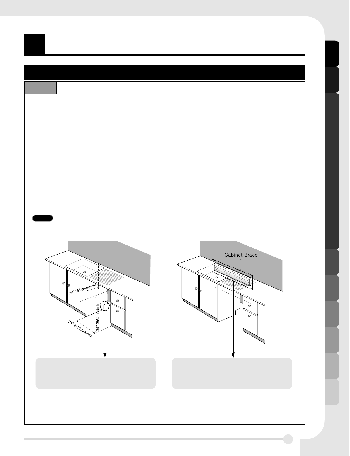
PREPARE CUPBOARD OPENINGStep 1
1. This dishwasher is designed to fit a standard dishwasher opening as shown below.
2. Select a location as close to sink as possible for easy connections to water and drain lines.
3. The dishwasher should not be installed more than 10 ft. (3m) from the sink for proper
drainage.
4. If dishwasher is to be installed in a corner, a minimum of 2 in. (50mm) is required between
the dishwasher and an adjacent a wall.
5. To allow for proper clearance of plumbing and electrical measure a 4
″x7″target area (figure
#1) on the side of the cabinet where the cabinet meets the back wall. Using a 2 1/2
″
diameter hole saw drill a hole (in the target area) within 6 3/4″from the floor, and no more
than an 3
″from the back wall. If there is a floor in the cabinet under the sink, it will also be
necessary to drill or cut through the floor to connect the water and drain under the sink.
NOTE Failure to cut this opening will result in the drain hose interfering with the rear wall not allowing
for flush mount installation.
Must have this opening (on either
side) to route plumbing and
electrical.
For FLUSH INSTALL, you may
remove the Cabinet brace inside of
the cabinet carefully.
■ Ensure the floor under the dishwasher is at the same level as the rest of the room to
allow for any service requirements.
These installation instructions are intended for use by Qualified lnstallers.
figure #1 figure #2
Page 6
INSTALLATION INSTRUCTIONS
II
NNSSTTAALLLLAATTIIOONN IINNSSTTRRUUCCTTIIOONNSS
6
Step 2 PREPARE THE ELECTRICAL WIRING
WARNING!
For personal safety, remove house fuse or open circuit breaker before
installation. Do not use an extension cord or adapter plug with this dishwasher.
Electrical and grounding connections must comply with the national electrical
code/provincial and municipal code and/or other local codes.
1. This appliance must be operated with correct voltage as shown in this manual and on the
rating plate, and connected to an individual, properly grounded branch circuit, protected by
time delay fuse. Wiring must be 3 wires including ground.
2. The wiring or cord should be in an accessible location adjacent to, and not behind the
dishwasher and within 4 ft. (1.2m) of the dishwasher side.
3. The wiring or cord must be grounded properly, if in doubt, have it checked by a qualified
electrician. No other appliance shall be connected to the same outlet by a double adapter
or similar plug.
4. The wiring or cord must be oriented as shown in Figure below.
5. Check the dishwasher for any damage before trying to install it.
6. Make sure Electrical line are oriented in the bottom channels as shown in the figure below.
If you find any damage to the dishwasher, Please contact your dealer or builder
immediately.
Electrical Cable
4 1/2″ - 6″(115 - 152mm)
These installation instructions are intended for use by Qualified lnstallers.
Page 7
INSTALLATION INSTRUCTIONS
II
NNSSTTAALLLLAATTIIOONN IINNSSTTRRUUCCTTIIOONNSS
7
Step 3
Step 4
PREPARE THE WATER SUPPLY CONNECTION
PREPARE DISHWASHER
WARNING!
1. This dishwasher must be connected to a hot water supply between 120℉(49℃)~149℉(65℃).
This temperature range provides the best washing results and shortest cycle time.
Temperature should not exceed 149
℉(65℃) to prevent damage to dishes.
2. When connecting the dishwasher water line, sealing tape or compound should be used to
avoid leaks.
3. When connecting the dishwasher water line, the house supply should be shut off.
4. The Water Supply Tube must be oriented in the bottom channels as shown in the figure below.
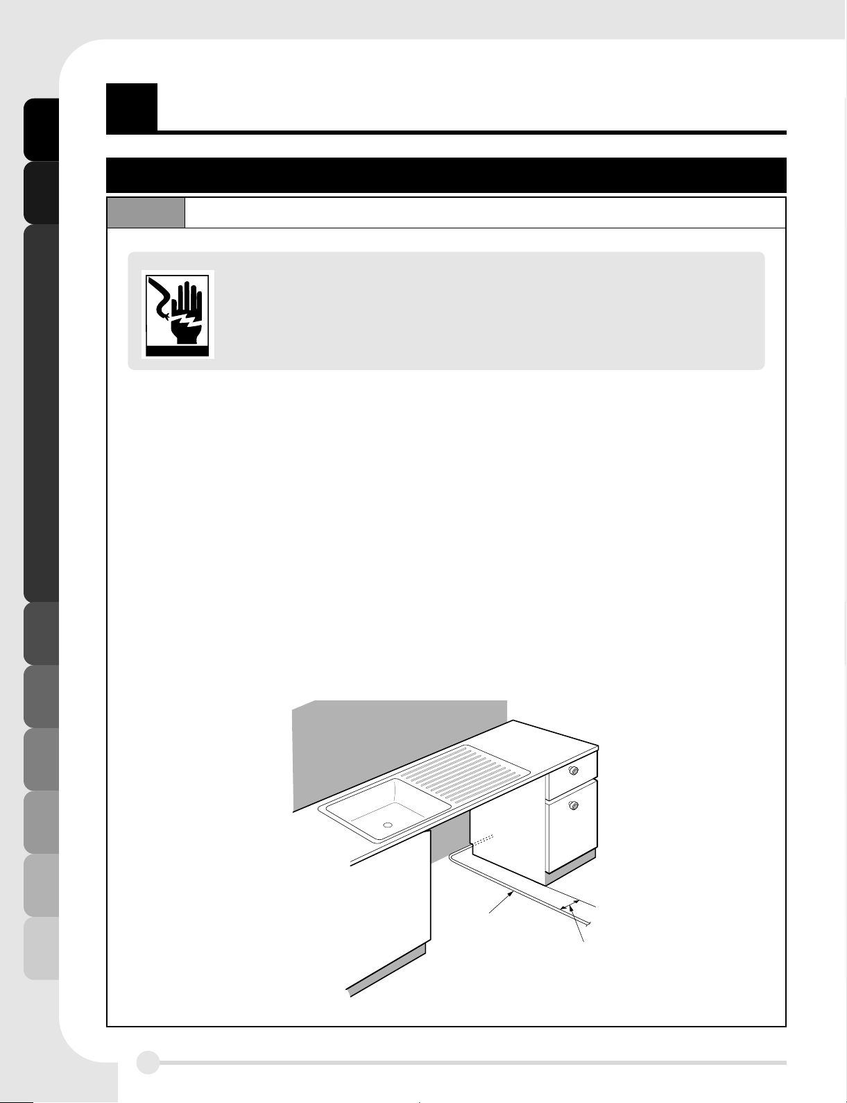
Open door and
grab body frame and top
front opening of tub.
Don’t pull handle.
Doing so can result in door distortion.
Electrical Cable
Water Supply
Tube
6 1/2″- 7 3/4″(165 - 197mm)
These installation instructions are intended for use by Qualified lnstallers.
Page 8
INSTALLATION INSTRUCTIONS
II
NNSSTTAALLLLAATTIIOONN IINNSSTTRRUUCCTTIIOONNSS
8
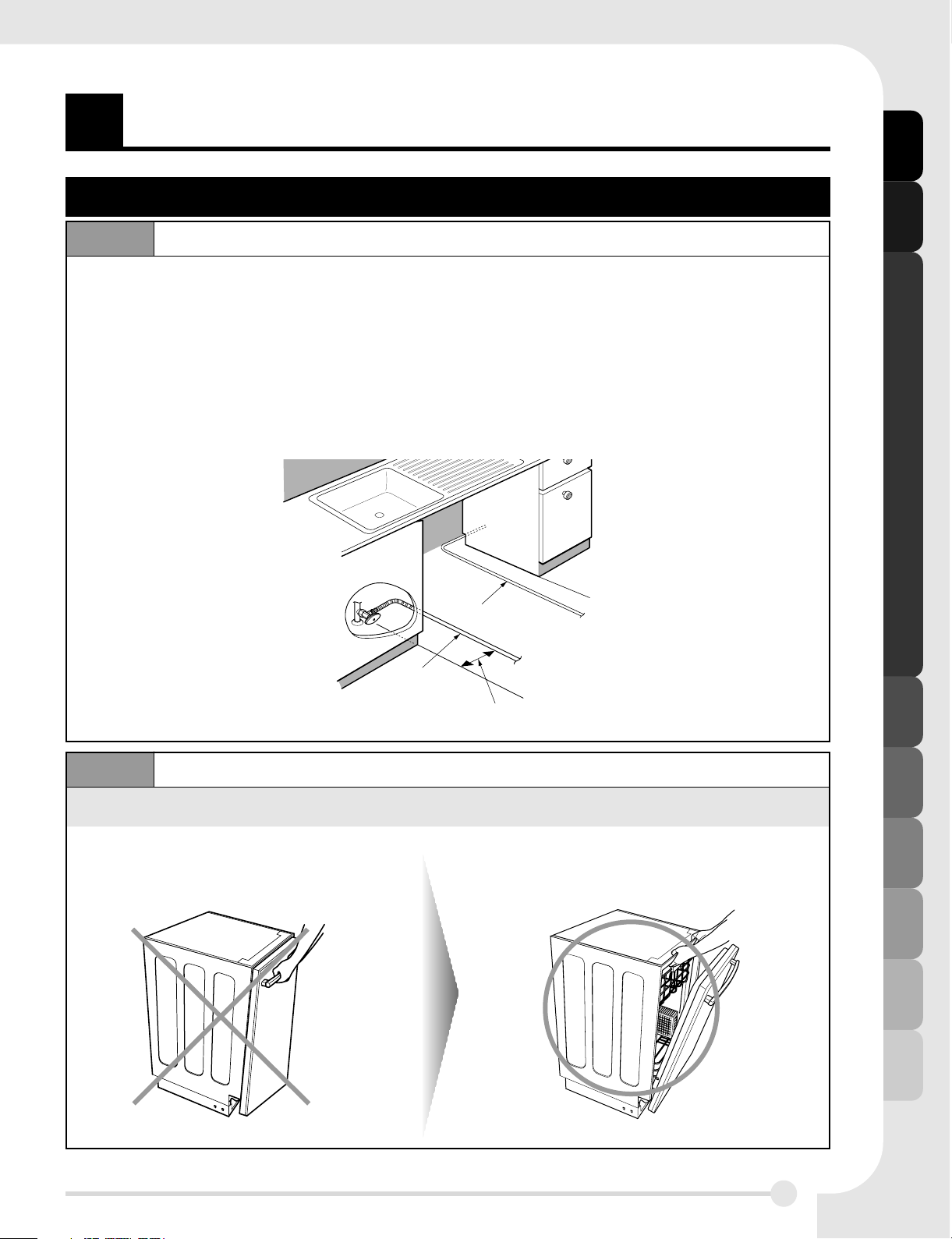
Step 5
Step 6
REMOVE LOWER COVER
FITTING 90
。。
ELBOW
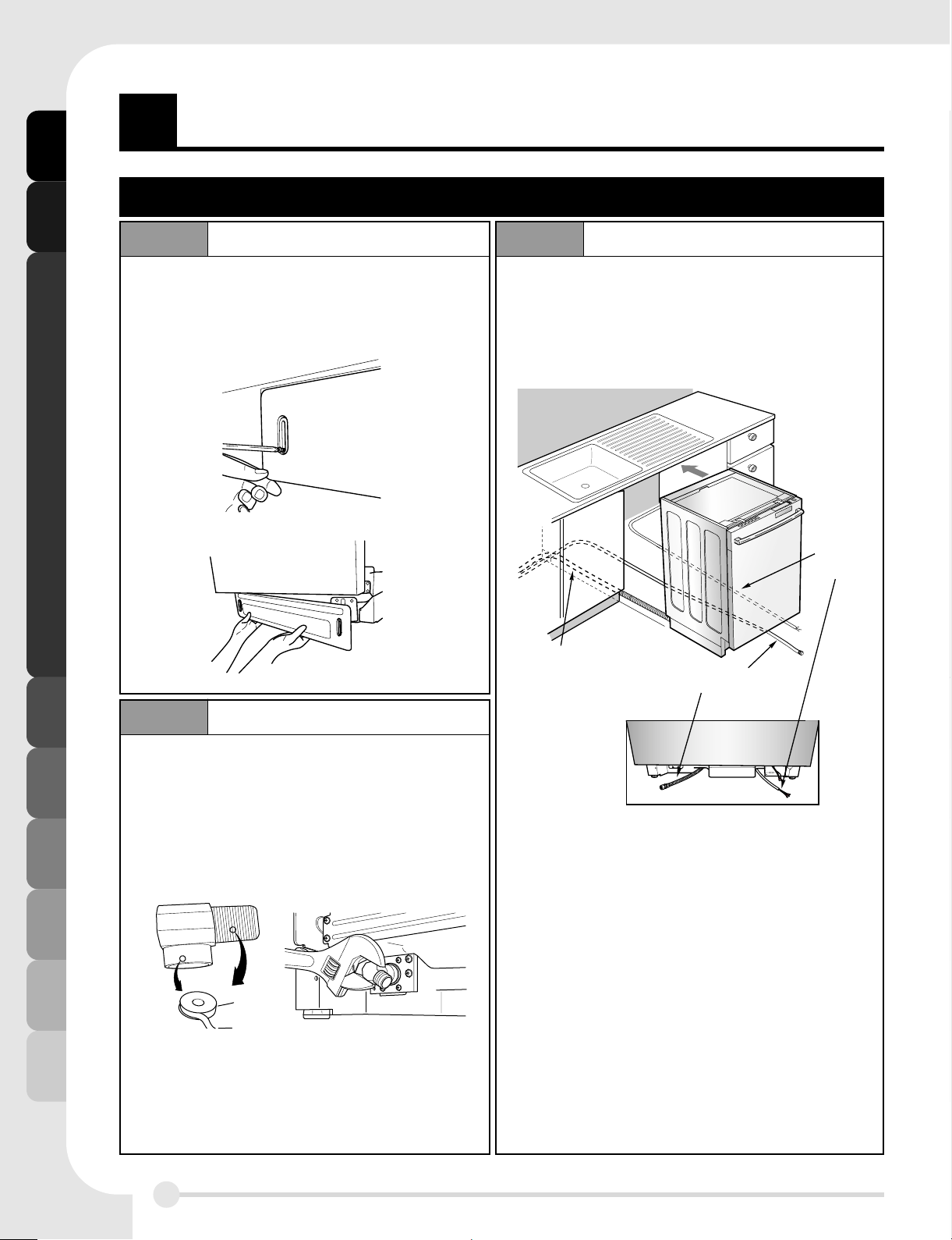
Step 7
SLIDE DISHWASHER INTO CABINET
Drain Hose
Water Supply Tube
Electrical
Cable
Remove two screws attaching lower cover
to dishwasher.
Remove lower cover from base.
Slide the dishwasher into the cabinet opening
carefully.
Make sure the drain hose inside the cabinet
is not kinked.
When fitting elbow into the inlet valve,
sealing tape or sealing compound should
be used to avoid water leaks.
Install a 90。elbow onto the water valve.
These installation instructions are intended for use by Qualified lnstallers.
Page 9

INSTALLATION INSTRUCTIONS
II
NNSSTTAALLLLAATTIIOONN IINNSSTTRRUUCCTTIIOONNSS
9
Step 8
Step 9
LEVEL DISHWASHER
SECURE DISHWASHER TO THE COUNTERTOP
Secure dishwasher to the countertop or the cabinet.
When the countertop is made of wood or will not be damaged by drilling, use Step 9-1.
When the countertop is made of granite, marble or others which could be damaged by
drilling, Use Step 9-2.
Check that the dishwasher is level. (Fig. A)
Attach level on top front opening of tub from side to side
Check that the dishwasher is plumb. (Fig. B)
Attach level on front side of cabinet
Check that gap between door and tub is equal on both side’s
(L, R) (Fig. C)
If the dishwasher is not level or both side gap is not equal,
adjust four leveling feet up or down until dishwasher is level
and both side gap is equal. (Fig. D)
1. Remove the Plastic Bushing
2. Drive Wood Screw through the hole
(Install Bracket is located between tub
and side cabinet by manufacturer)
3. Reinstall Plastic Bushings.
STEP 9-1
Fig. D
STEP 9-2
Important Tip
1) Cover the Filter Hole by towels to prevent screws from falling down to pump.
2) Use a Magnetic Drive to prevent screws from falling down into the gap in step9-2.
Plastic Bushing
Wood Screw
1. Locate the installation brackets in the slot
2. Bend the brackets to secure them to the
dishwasher tub
3. Secure the dishwasher to the countertop
with the screws provided through the
holes in the bracket
These installation instructions are intended for use by Qualified lnstallers.
LR
Fig. C
Fig. B
Fig. A
Page 10

INSTALLATION INSTRUCTIONS
II
NNSSTTAALLLLAATTIIOONN IINNSSTTRRUUCCTTIIOONNSS
10
Step 10 DRAIN LINE CONNECTION
1. If the end of the drain hose does not fit to the drain line, use an adapter (not supplied) that
must be resistant to heat and detergent and may be obtained from a plumbing shop.
2. There are 2 typical connections as shown in Fig. E & F.
① There may be other options than shown here for connection of the drain hose. The drain
connection must meet local plumbing regulations.
② The S trap spigot must be drilled out cleanly and free of obstruction to its maximum
internal diameter, if used for drainage.
③ To prevent syphoning, one of the following instruction methods must be followed:
Fig. E:
Connection to Disposer or Waste Tee.
Fig. F:
Connection to Air Gap.
�Follow local codes and
ordinances.
�Do not exceed 10 ft. (3m)
distance to drain.
�Do not connect drain lines from
other devices to the dishwasher
drain hose.
Drain Requirements
These installation instructions are intended for use by Qualified lnstallers.
Min. 20″(508mm)
Min. 30″(770mm)
Max. 40″(1000mm)
Sink
Sink
Air Gap
Rubber
Connector
Drain Hose
Drain Hose
Dishwasher
Dishwasher
Min. 20″(508mm)
Min. 30″(770mm)
Max. 40″(1000mm)
Page 11

INSTALLATION INSTRUCTIONS
II
NNSSTTAALLLLAATTIIOONN IINNSSTTRRUUCCTTIIOONNSS
11
Step 11
Step 12
WATER SUPPLY CONNECTION
ELECTRICAL POWER CONNECTION
1. Before connecting, turn off the
water supply.
2. After fitting the Elbow into the
Inlet Valve, slide the Flexible
Stainless Tube or Copper Tube
into the Elbow.
3. Tighten the nut and make sure
that the line is not kinked or
sharply bent.
Step 13 FINAL CHECK
1. Turn electrical power back on at the circuit breaker.
2. Turn house water supply back on.
3. Operate the dishwasher through one cycle (Quick cycle is recommended) to check for water
leaks and operating conditions.
4. Replace the Lower Cover.
1. Before beginning, turn off
electrical power to the unit at
the circuit breaker.
2. Remove the Junction Cover
and then Install the Strain
Relief.
3. Twist Wire Connectors tightly
on the wires. Wrap each
connection with Electrical tape.
4. Check again and make sure
that all wires are connected
correctly, black to black, white
to white, green to green
(ground to ground).
5. Replace the
Junction Cover.
These installation instructions are intended for use by Qualified lnstallers.
Inlet V alve
Elbow
Water Supply Tube
Wire Connector
Junction Case
Strain Relief
Junction Cover
black to black
green to green
(ground to ground)
white to white
Page 12

P/No.: 3828DD3003A
Page 13

Antes de instalar su lavavajillas le rogamos que lea
detenidamente este manual y lo guarde futuras consultas.
Si tiene alguna duda, llámenos al 1-800-243-0000
o visite nuestra web en: http://www.lgservice.com
o http://us.lgservice.com
MODEL : LDF7810WW / LDF7810BB / LDF7810ST
LDF7811WW / LDF7811BB / LDF7811ST
LDS5811WW / LDS5811BB / LDS5811ST
LDF6810WW / LDF6810BB / LDF6810ST
Page 14

SS
EEGGUURRIIDDAADD YY PPRREECCAAUUCCIIÓÓNN
2
íí
NNDDIICCEE
PARTE 1. SEGURIDAD Y PRECAUCIÓN ................................................................................... 2
PARTE 2. ESPECIFICACIONES DEL LAVAVAJILLAS ............................................................... 3
PARTE 3. HERRAMIENTAS Y MATERIALES NECESARIOS ..................................................... 4
PARTE 4. INSTRUCCIONES DE INSTALACIÓN ................................................................... 5~11
SEGURIDAD Y PRECAUCIÓN
• Desconecte la corriente eléctrica antes de empezar!
• Todas las conexiones eléctricas y la toma de tierra deben efectuarse de conformidad con las
normas nacionales y locales.
• Si la alimentación eléctrica resulta dañada, deberá sustituirla solamente el fabricante o su
agente de servicio o un técnico suficientemente cualificado para evitar riesgos.
• Este lavavajillas debe conectarse a un suministro de agua caliente entre 49℃ ~ 65℃.
Con este intervalo de temperaturas se consiguen los mejores resultados de lavado y el ciclo de
tiempo más corto. La temperatura no debe superar los 65℃ para evitar daños en los platos.
• Este aparato ha de emplazarse de modo que sea posible conectar la corriente eléctrica.
• Este aparato se ha de conectar al suministro de agua utilizando mangueras nuevas.
No deben reutilizar mangueras viejas.
INSTRUCCIONES DE CONEXIÓN A TIERRA
• Para un lavavajillas permanentemente conectado:
Este aparato debe ser conectado a un sistema de cableado permanente con toma metálica de
tierra, o bien ha de haber un conductor de puesta a tierra del equipo con los conductores del
circuito y conectarlo al terminal o cable conductor de puesta a tierra del aparato.
ADVERTENCIA!
Cuando instale y use su lavavajillas, adopte medidas básicas de precaución, como
son las siguientes:
!
INSTRUCCIONES IMPORTANTES DE SEGURIDAD
Page 15

3
EE
SSPPEECCIIFFIICCAACCIIOONNEESS DDEELL LLAAVVAAVVAAJJIILLLLAASS
ESPECIFICACIONES DEL LAVAVAJILLAS
Product Dimension
■ Fuente de alimentación:
120 V, 60 Hz de c.a. solamente
■ Presión de agua:
20
-120 psi (140-830 kPa)
■ Dimensiones
(Anchura x Profundidad x Altura):
23 7/8
″″
X 24 5/8″″X 33 7/8
″″
(606mm x 625mm x 860mm)
■ Temperatura de entrada de agua:
120
℉(49℃)
■ Peso:
115 lbs. (52 kg, Totalmente integrado),
110 lbs. (50 kg, Semiintegrado)
Las especificaciones están sujetas a
modificaciones para mejorar el
rendimiento.
33-7/8″
(860mm)
20-3/8″(518mm)
6-3/4″
(171mm)
3″(76mm)
23-7/8″(606mm)
24-5/8″(625mm)1/5″(5mm)
Totalmente integrado
LDF7810WW/BB/ST
LDF7811WW/BB/ST
LDF6810WW/BB/ST
Semiintegrado
LDS5811WW/BB/ST
NOTA Las características de su
lavavajillas pueden ser diferentes
de las ilustraciones que siguen.
Page 16

4
HH
EERRRRAAMMIIEENNTTAASS YY MMAATTEERRIIAALLEESS NNEECCEESSAARRIIOOSS
HERRAMIENTAS Y MA TERIALES NECESARIOS
SOPORTE DE INSTALACIÓN TORNILLO DE MADERA
MMAATTEERRIIAALLEESS PPAARRAA LLAA IINNSSTTAALLAACCIIN
N
SOPORTE DE
INSTALACIÓN
TUBO DE
SUMINISTRO DE AGUA
CODO
ACCESORIOS
DE TUBO
CONECTOR
DE GOMA
CINTA DE
FONTANERO
SEPARADOR
DE AIRE
ABRAZADERA
DE MANGUERA
PRESILLA DE
AJUSTE DE TENSIÓN
CINTA
AISLANTE
CONECTOR DE HILOS
DE TORSIÓN
HHEERRRRAAMMIIEENNTTAASS PPAARRAA LLAA IINNSSTTAALLAACCIIN
N
DESTORNILLADOR
NORMAL
LLAVE
AJUSTABLE
DESTORNILLADOR
PHILLIPS
FRESA DE
BARRENAR
CINTA MÉTRICA
CUCHILLA
DE CORTE
NIVEL DE
BURBUJA
CORTADORA
DE TUBOS
TALADRO
ELÉCTRICO
GUANTES
GAFAS
PROTECTORAS
TENAZAS ALICATES
ALICATES
PELACABLES
PPIIEEZZAASS SSUUMMIINNIISSTTRRAADDAAS
S
Page 17

5
II
NNSSTTRRUUCCCCIIOONNEESS DDEE IINNSSTTAALLAACCIIÓÓNN
I NSTRUCCIONES DE INSTALACIÓN
PREPARACIÓN DEL ALOJAMIENTO DEL ARMARIOPaso 1
Esta instruccion de instalacion es hecha para ser usado por instaladores calificados.
1. Este lavavajillas está diseñado para las dimensiones mostradas en la figura.
2. Elija un lugar lo más cerca posible del fregadero para facilitar las conexiones de suministro
de agua y de desagüe.
3. El lavavajillas no debe instalarse a más de 10 ft. (3m) del fregadero para conseguir un
desagüe correcto.
4. Si se va a instalar el lavavajillas en una esquina, es necesario dejar un espacio mínimo de 2
in. (50mm) entre el aparato y la pared contigua
5. Debe cortar un orificio de 4
″x 7″en el lateral del armario, donde éste toca la pared
posterior, a fin de permitir una holgura correcta para la canalización y los cables. Usando un
orificio con un diámetro de 2 1/2
″el cual se deberá perforar (en el área establecida) lo
profundo del suelo a 6 3/4
″o y no mas de 3″de la pared trasera.
NOTA No cortar este orificio causará que la manguera de drenaje interfiera con la pared posterior, no
permitiendo la instalación del montaje de drenaje.
Refuerzo del armario
Debe tener este orificio (en el lado
del fregadero) para tender la
canalización y los cables y lograr la
instalación correcta.
Para la INSTALACIÓN DEL
DESAGÜE retire cuidadosamente el
refuerzo del armario del interior del
armario.
■ Asegúrese de que el suelo debajo del lavavajillas está al mismo nivel que el resto de la
habitación para tener en cuenta cualquier requisito de servicio.
figura #1 figura #2
Page 18

I NSTRUCCIONES DE INSTALACIÓN
II
NNSSTTRRUUCCCCIIOONNEESS DDEE IINNSSTTAALLAACCIIÓÓNN
6
Paso 2 PREPARACIÓN DEL CABLEADO ELÉCTRICO
Esta instruccion de instalacion es hecha para ser usado por instaladores calificados.
ADVERTENCIA!
Para seguridad personal, quite el fusible o abra el disyuntor de la vivienda antes
de iniciar la instalación. No use ningún cable de prolongación o enchufe
adaptador con este lavavajillas. Las conexiones eléctricas y de toma de tierra
han de cumplir la reglamentación eléctrica nacional, provincial y municipal y/u
otras normas locales.
1. Este aparato ha de funcionar con el voltaje correcto indicado en este manual y en la placa
de características, y se ha de conectar a un circuito de ramificación individual
debidamente conectado a tierra, y protegido por un fusible temporizado. El cableado ha
de tener 3 hilos incluyendo tierra.
2. El cableado o cordón debe estar en un lugar accesible, junto al lavavajillas (pero no
detrás), y a no más de 4 ft. (1.2m) del lado del aparato.
3. El cableado o cordón ha de estar correctamente puesto a tierra. En caso de duda, avise a
un electricista calificado para que lo compruebe. No debe conectarse ningún otro aparato
a la misma toma del enchufe utilizando un doble adaptador o enchufe similar.
4. El cableado o cordón ha de estar orientado según se indica abajo en la Figura.
5. Compruebe si tiene algún desperfecto el lavavajillas antes de intentar instalarlo.
6. Asegúrese que el cable de alimentación está orientado en el canal inferior como muestra
la siguiente figura. Si descubre daños en el lavavajillas, por favor póngase
inmediatamente en contacto con su distribuidor o fabricante.
4 1/2″ - 6″(115 - 152mm)
Page 19

I NSTRUCCIONES DE INSTALACIÓN
II
NNSSTTRRUUCCCCIIOONNEESS DDEE IINNSSTTAALLAACCIIÓÓNN
7
Abra la puerta y sujete la carcasa y la
parte superior delantera de la unidad.
No tire del mango.
Hacerlo podría causar la deformación de
la puerta.
Paso 3
Paso 4
PREPARACIÓN DE LA CONEXIÓN DE SUMINISTRO DE AGUA
POR FAVOR, PREPARE LAVAVAJILLA
ADVERTENCIA!
Esta instruccion de instalacion es hecha para ser usado por instaladores calificados.
1. Este lavavajillas debe conectarse a un suministro de agua caliente entre 49℃ ~ 65℃.
Con este intervalo de temperaturas se consiguen los mejores resultados de lavado y el ciclo
de tiempo más corto. La temperatura no debe superar los 65
℃ para evitar daños en los
platos.
2. Cuando conecte la tubería de suministro del agua del lavavajillas, debe utilizar cinta aislante
o mástique de sellado para evitar fugas.
3. Corte el suministro de agua de la casa cuando conecte la tubería del agua del lavavajillas.
4. El conducto del suministro de agua debe estar orientado en el canal inferior como muestra
la siguiente figura.
6 1/2″- 7 3/4″(165 - 197mm)
Page 20

I NSTRUCCIONES DE INSTALACIÓN
II
NNSSTTRRUUCCCCIIOONNEESS DDEE IINNSSTTAALLAACCIIÓÓNN
8
Retire los dos tornillos de fijación de la
cubierta inferior del lavavajillas.
Retire la cubierta inferior de la base.
Deslice con cuidado el lavavajillas dentro del
alojamiento del armario.
Asegúrese de que no está retorcida la
manguera de desagüe dentro del armario.
Al fijar el codo en la válvula de entrada,
utilice cinta selladora o compuesto de
sellado a fin de evitar posibles fugas de
agua.
Instale un codo de 90。sobre la válvula de
entrada de agua.
Paso 5
Paso 6
RETIRE LA CUBIERTA INFERIOR
FIJACIÓN DE UN CODO DE 90
。。
Paso 7
DESLICE EL LAVAVAJILLAS EN EL INTERIOR DEL ARMARIO
Esta instruccion de instalacion es hecha para ser usado por instaladores calificados.
Page 21

I NSTRUCCIONES DE INSTALACIÓN
II
NNSSTTRRUUCCCCIIOONNEESS DDEE IINNSSTTAALLAACCIIÓÓNN
9
Compruebe que el lavavajillas esté nivelado. (Fig. A)
Acóplelo en la abertura superior delantera de lado a lado.
Compruebe que el lavavajillas esté instalado verticalmente.
(Fig. B)
Acóplelo en la abertura superior delantera del lado del
armario.
Compruebe que la holgura entre la puerta y la unidad sea
igual en ambos lados (I, D). (Fig. C)
Si el lavavajillas no está nivelado en ambos lados, ajuste
los cuatros pies de nivelado
subiéndolos o bajándolos
hasta que el lavavajillas está nivelado en ambos lados.
(Fig. D)
Fig. D
LR
Fig. C
Fig. B
Fig. A
Paso 8
Paso 9
NIVELE EL LAVAVAJILLAS
FIJE EL LAVAVAJILLAS A LA ENCIMERA
Esta instruccion de instalacion es hecha para ser usado por instaladores calificados.
Fije el lavavajillas a la encimera del armario. Cuando la encimera esté hecha de madera,
ésta no sufrirá daños al perforarse; siga el paso 9-1 Cuando la encimera esté hecha de
granito, mármol u otros materiales similares, la perforación podría dañarla; siga el paso 9-2.
1.Retire el casquillo de plástico.
2.Inserte el tornillo de madera a través
del orificio. (instale la abrazadera
situada entre la unidad y el armario
lateral por el fabricante.)
3.Cubra el orificio con un casquillo de
plástico.
Paso 9-1 Paso 9-2
Importante
1)Cubra el orificio de filtrado con una toalla a fin de evitar la caída de los tornillos.
2)Utilice un imán a fin de evitar la caída de los tornillos en la separación del paso9-2.
Casquillo de
plástico
Tornillo de madera
1.Coloque las abrazaderas de instalación en
la ranura.
2.Doble las abrazaderas a fin de
asegurarlas en la unidad del lavavajillas.
3.Fije el lavavajillas a la encimera con los
tornillos incluidos a través de los orificios
de la abrazadera.
Page 22

I NSTRUCCIONES DE INSTALACIÓN
II
NNSSTTRRUUCCCCIIOONNEESS DDEE IINNSSTTAALLAACCIIÓÓNN
10
1. Si el extremo de la manguera de desagüe no se adapta a la línea de desagüe, utilice un
conector de goma (no suministrado) que sea resistente al calor y al detergente, y que
puede obtener en una tienda de fontanería.
2. Hay 2 formas típicas de conexión que se muestran en las Figuras E y F.
① Los métodos recomendados para la conexión de la manguera de desagüe deben
seguirse en las zonas de la Water Board Authority. Fuera de estas zonas se utilizan
normalmente otras diversas opciones, siendo el ayuntamiento o los fontaneros locales
quienes han de asesorar al respecto.
② La espiga del sifón en S ha de estar perforada limpiamente y sin ningún obstáculo en
todo su máximo diámetro interno, si se utiliza para desagüe.
③ Para evitar la acción del sifón, se han de seguir las instrucciones de uno de los dos
métodos siguientes:
Paso10 CONEXIÓN DE LA LÍNEA DE DESAGÜE
Esta instruccion de instalacion es hecha para ser usado por instaladores calificados.
Fig. F: Conexión a un separador de aire.
Fig. E: Conexión a un evacuador o a una T de descarga.
Requisitos del desagüe
�Siga la normativa y ordenanzas
locales.
�No debe haber más de 10 ft.
(3m) de distancia hasta el
desagüe.
�No conecte conducciones de
desagüe de otros aparatos a la
manguera de desagüe del
lavavajillas.
Fregadero
Lavavajillas
Manguera
de desagüe
Min. 20″(508mm)
Min. 30″(770mm)
Max. 40″(1000mm)
Separador de aire
Lavavajillas
Fregadero
Manguera de
desagüe
Conector
de goma
Min. 20″(508mm)
Min. 30″(770mm)
Max. 40″(1000mm)
Page 23

I NSTRUCCIONES DE INSTALACIÓN
II
NNSSTTRRUUCCCCIIOONNEESS DDEE IINNSSTTAALLAACCIIÓÓNN
11
Paso 11
Paso 12
CONEXIÓN DE LA RED DE SUMINISTRO DE AGUA
CONEXIÓN DE LA CORRIENTE ELÉCTRICA
1. Cuando efectúe la conexión, debe utilizar
cinta aislante o mástique de sellado para
evitar fugas.
2. Antes de efectuar la conexión, corte el
suministro de agua de la red.
3. Después de instalar el codo en la válvula
de entrada, deslice el tubo flexible de
acero inoxidable o el tubo de cobre
dentro del codo.
Paso 13 COMPROBACIONES FINALES
1. Vuelva a conectar la corriente eléctrica en el disyuntor.
2. Vuelva a abrir el suministro de agua de la casa.
3. Haga funcionar el lavavajillas durante un ciclo (se recomienda un ciclo rápido) para
comprobar si hay fugas de agua y observar las condiciones de operación.
4. Vuelva a colocar la tapa inferior.
V lvula de entrada
Tubera de
suministro de agua
Codo
1. Antes de empezar, desconecte
la alimentación eléctrica de la
unidad en el disyuntor.
2. Quite la tapa de unión e instale
luego la presilla de ajuste de
tensión de los cables.
3. Torsione y apriete fuertemente
los conectores sobre los hilos
conductores. Arrolle cada
conexión con cinta aislante.
4. Compruebe de nuevo y
asegúrese de que todos los
hilos están conectados como
es debido, negro con negro,
blanco con blanco y verde con
verde (tierra con tierra).
5. Vuelva a colocar
la tapa de unión.
P
Esta instruccion de instalacion es hecha para ser usado por instaladores calificados.
Tapa de unión
Conector de hilos
Caja de conexiones
resilla de ajuste de
tensión de cables
negro con negro
tierra con tierra
blanco con blanco
Page 24

N。de Ref.: 3828DD3003A
 Loading...