

LG LD-4080W, LD-4080T, LD-4080WB, LD-4080TB, LD-4080WU Service Manual
...
P/No. : 3828ED3001Y

CONTENTS
1. CAUTION......................................................................................................................... 4
2. SPECIFICATIONS ........................................................................................................... 5
3. FEATURES & TECHNICAL EXPLANATION................................................................... 6
4. PARTS NAME.................................................................................................................. 9
5. WIRING DIAGRAM...................................................................................................... 10
6. PROGRAM CHART (SCHEMATIC DIAGRAM) ............................................................ 11
7. HOW TO DISASSEMBLE ............................................................................................ 12
7-1. FULL DISASSEMBLE .......................................................................................... 12
7-2. DISASSEMBLE C-BASE ASSEMBLY ................................................................. 19
8. TROUBLE SHOOTING METHODS.............................................................................. 22
A. TROUBLE SHOOTING ACCORDING TO DISPLAYED ERROR MESSAGE.......... 22
B. TROUBLE DIAGNOSES AND REPAIR BY SYMPTOM........................................... 24
9. INSTALLATION INSTRUCTION................................................................................... 28
10. EXPLODED VIEW ...................................................................................................... 33
11. REPLACEMENT PART LIST........................................................................................39
- 3 -

CAUTION !
�
DISCONNECT POWER CORD BEFORE SERVICING
�
RECONNECT ALL GROUNDING DEVICES
IMPORTANT SAFETY NOTICE !
This service information is intended for individuals
possessing adequate backgrounds of electrical,
electronic and mechanical experience.
Any attempt to repair this appliance may result in
personal injury and property damage.
The manufacturer or seller can not be responsible
for the interpretation of this information, nor can it
assume any liability in connection with its use.
- 4 -
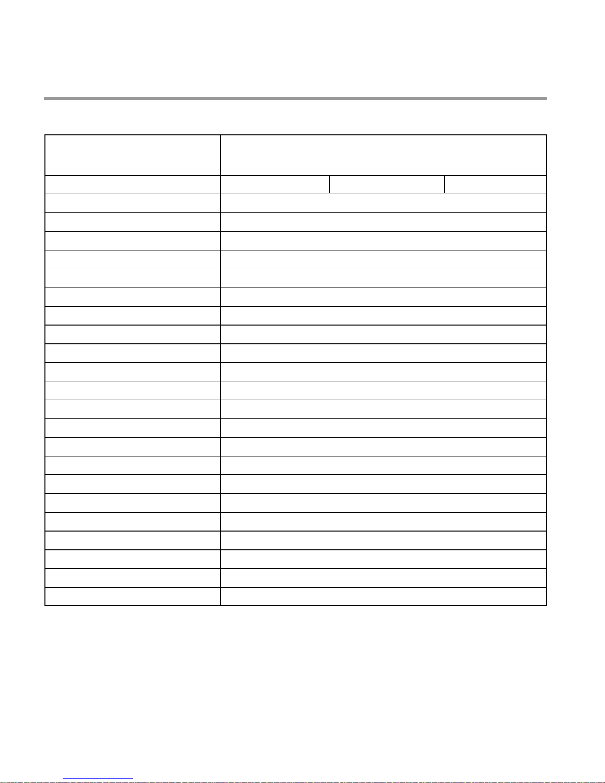
2. SPECIFICATION
ITEM
Rated Voltage / Frequency AC 220V/50Hz AC 230V/50Hz AC 240V/50Hz
Installation Free Standing / Built-Under / Built-In
Place Settings 14
Product Dimension(mm)
Product Weight(Kg) 56 / 50 / 48
Door Colour White / STS
Tub Material Stainless Steel
Control Electronic
Rated Power(Watt) 2,210
Heater Power(Watt) 2,100
Programs 6
Upper Rack Position Adjustable
Lower Rack 100% Fold down
Water Consumption(ℓ) 15 (Eco)
600(W)× 600(D)× 850(H) / 598(W)× 576(D)× 817(H) / 598(W)× 562(D)× 817(H)
SPECIFICATION
Power Consumption (kWh) 1.05 (Eco)
Operating Time (min) Except Drying : 116(Except Drying):Economy
Fan Dry System Yes
Delay Start Function Yes
Auto-Off Power Switch Yes
Process Monitor Yes
Wash Level 5
Racks Nylon Coating
Operating Water Pressure (Bar) 0.5 ~ 8
- 5 -
3. FEATURES & TECHNICAL EXPLANATION
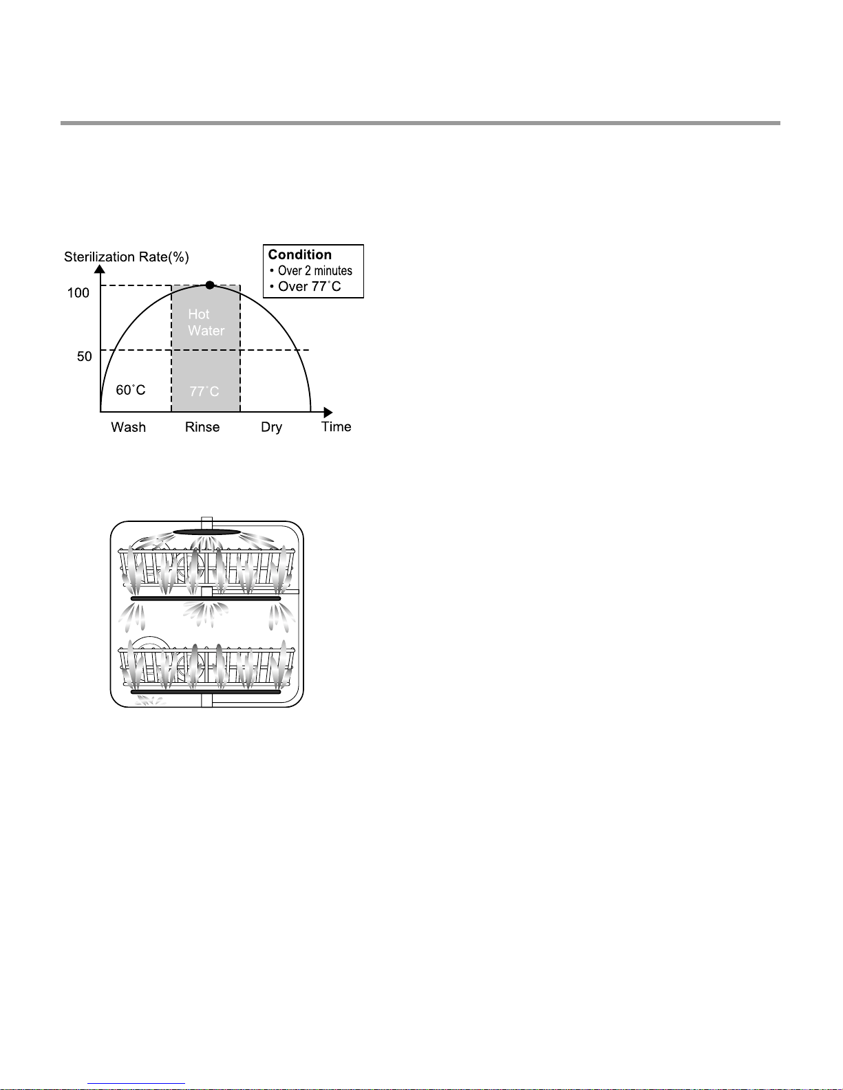
3-1 New Technology Introduction
3-1-1. High Temperature Rinsing
• During the high temp. Rinse course, water
temperature in an dishwasher reaches 77°C,
considerably higher than the average rinse
temperature in conventional
dishwashers(65°C). This is how Rinse 77°C
can eliminate some bacteria such as
salmonella.
3-1-2. Turbo Spray System
• Turbo Spray System is elaborately designed to
achieve a more powerful and efficient wash.
You can see the excellent 3 rotating spray arm
with 5 directional waterjet.
- 6 -
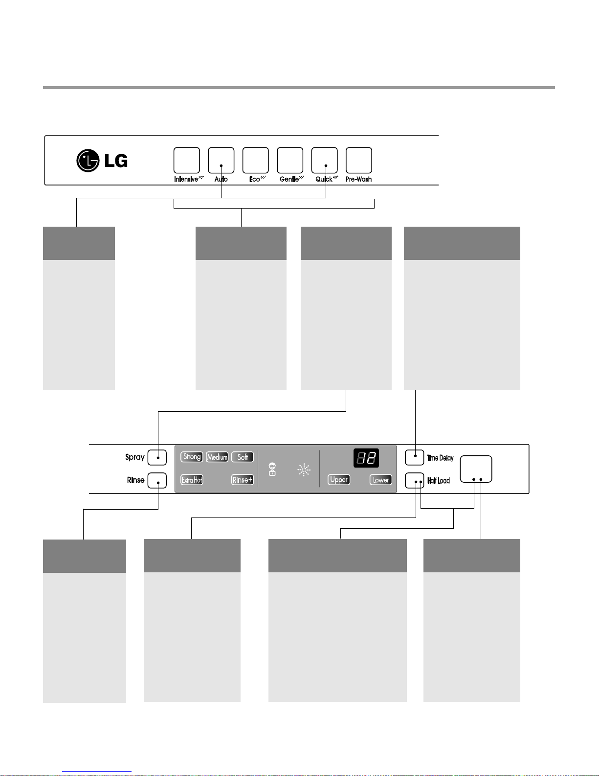
3-2. Display Panel
CHILD
LOCK
• Used to lock or
unlock the
control buttons
to prevent all
the setting from
being changed
by a child.
• For locking /
unlocking, press
Auto and Quick
button
simultaneously.
PROGRAM
• When you want to
select program, press
each button.
SPRAY
INTENSITY
• With each press, the
level of water jet is
changed to “Strong”,
“Medium”, and
“Soft”.
TIME DELAY
• If you want to delay the start
of selected program, press
this button before start.
• Pressing the delay time will
increase time by 1 hour.
• The delay start time can be
adjusted from 1 hour to 19
hours.
EXTRA HOT
/ RINSE+
• With each press,
77℃ extra hot,
Rinse+, 77℃
extra hot & Rinse+
is repeated.
HALF LOAD
• In case of small load, use
upper or lower rack only
to save energy .
• With each press, can
select upper or lower rack
only .
• In case you don’t select
this button, the machine
always works vario
washing, which operate
upper and lower spray
arm alternately .
BEEP ON / OFF
• The dishwasher must be switched
off.
• The beep on/off function can be
set by pressing the Half Load and
Power button simultaneously for
seconds, then a “on” will appear
in the time display.
• To change the setting, press the
Half Load button.
• The beep on/off function is
automatically canceled when
power failure occur.
- 7 -
POWER
• For operating, press
this button first for
power on.
• After operating, this
button automatically
switches off for safety
and energy saving.
• In case of irregular
surge disturbances to
the machine, the power
may be automatically
turned off for safety.
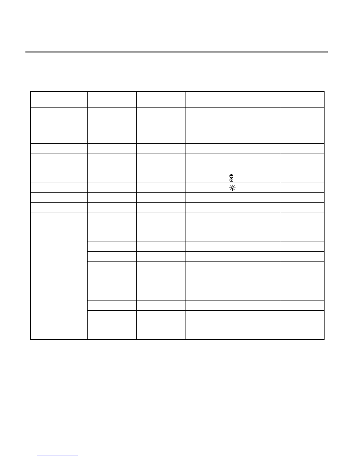
3.3 TEST MODE
CHECK PROGRAM(START IN THE STATE OF THE CLOSED DOOR)
BUTTON
Intensive+Auto
+POWER S/W
Intensive KEY
Auto KEY
Eco KEY
Gentle KEY
Quick KEY
Pre-Wash KEY
Spray KEY
Rinse KEY
Time Delay KEY
Half Load KEY
The number of
Pushing button
1 TIME
1 TIME
1 TIME
1 TIME
1 TIME
1 TIME 55
1 TIME
1 TIME
1 TIME
1 TIME
1 TIME
2 TIME
3 TIME
4 TIME
5 TIME
6 TIME
7 TIME
8 TIME
9 TIME
10 TIME
11 TIME
12 TIME
13 TIME
DISPLAY Load and Checking Points DOOR
n0
11
22
33
44
66
77
88
99
n1
n2
n3
n4
n5
n6
n7
n8
n9
Temperature
11
12
13
All LEDs are Lighting not concerned
Spray Intensity “Strong”LED is Lighting
Spray Intensity “Medium”LED is Lighting
Spray Intensity “Soft”LED is Lighting
Extra Hot LED is Lighting
Rinse + LED is Lighting
Child lock LED ( ) is Lighting
Rinse refill LED ( ) is Lighting
none
Half Load “Upper”LED is Lighting
Half Load “Lower”LED is Lighting
none
Washing moter
Drain Pump
Inlet valve
Dispenser
Heater(for 10 sec.)
Fan Moter
none
Thermister
Lower Nozzle
Upper Nozzle
AUTO OFF S/W
not concerned
not concerned
not concerned
not concerned
not concerned
not concerned
not concerned
not concerned
not concerned
not concerned
not concerned
closed
closed
closed
closed
closed
closed
closed
not concerned
closed
closed
not concerned
- 8 -
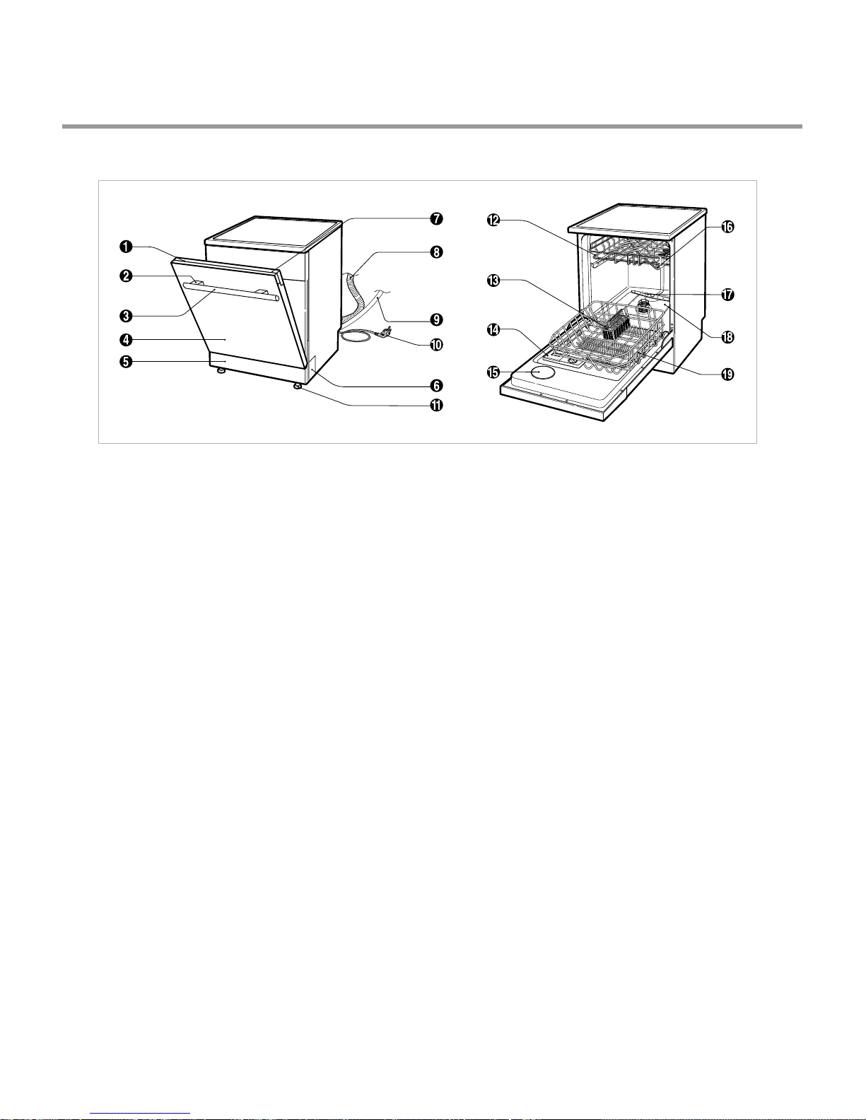
4. PARTS NAME
1. Control Panel
2. Handle deco
3. Door Handle
4. Front Cover
5. Lower Cover
6. Side Cabinet deco
7. Power Switch
8. Drain hose
9. Inlet Valve ASM
10. Power Cord
11. Adjust Leg
12. Upper Rack
13. Cutlery Rack
14. Detergent & Rinse Aid Dispenser
15. Vapor Vent Cover
16. Upper Spray Arm
17. Lower Spray Arm
18. Filter ASM
19. Lower Rack
- 9 -
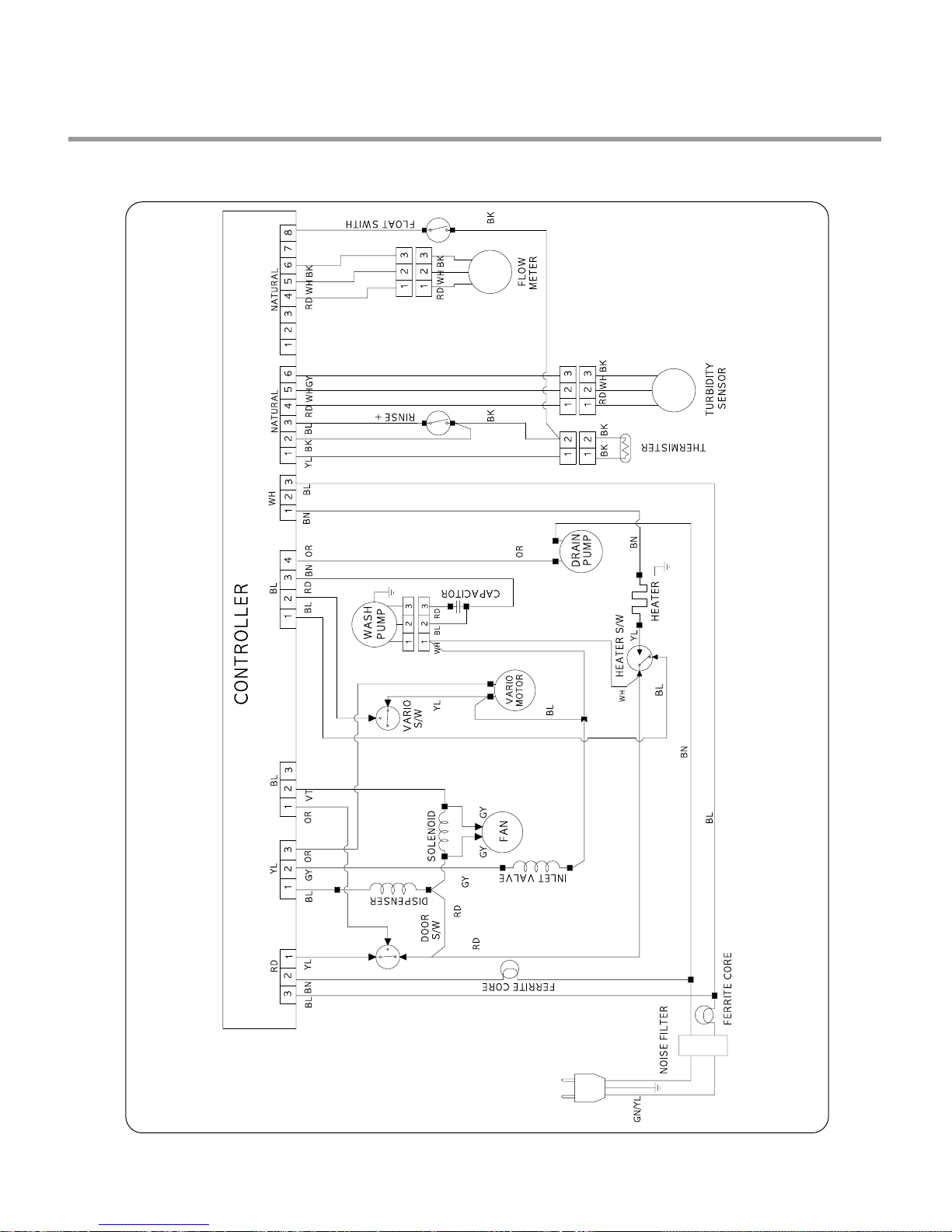
5. WIRING DIAGRAM
1. Fan dry
- 10 -
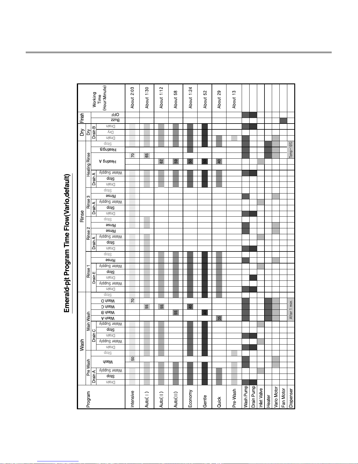
6. PROGRAM CHART(SCHEMATIC DIAGRAM)
- 11 -
7. HOW TO DISASSEMBLE
BEFORE DISASSEMBLING THE DISHWASHER ;
1) Remove the plug from electric outlet to avoid electric shock.
2) Close the Water Tap(faucet).
3) Remove all dishes and items in the dishwasher.
4) Remove the Lower Rack and the Upper Rack.
5) In case of the water softner assembly model, open the water softner cap to flow out the
water to sump and drain to avoid the floor wet.
6) If necessary, remove the inlet hose and drain hose to avoid the hose damages.
7) Prepare some towels to avoid floor wet by the water left in the dishwasher.
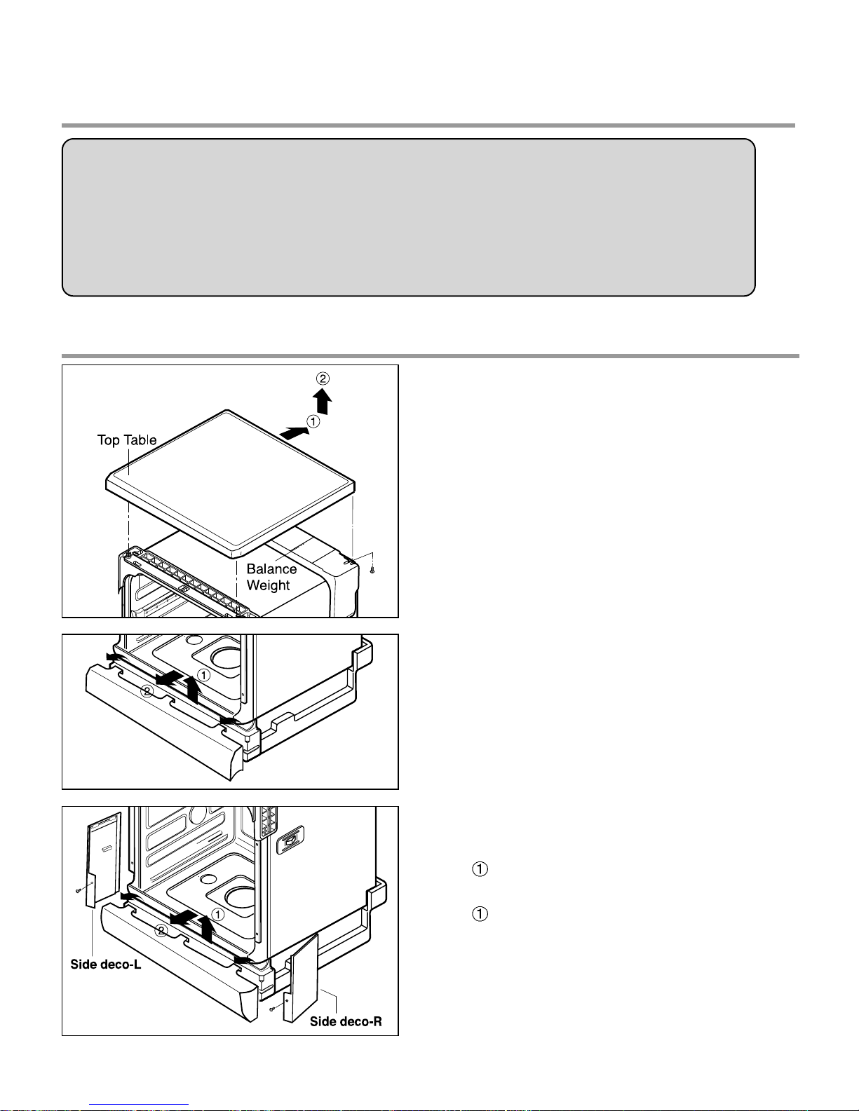
7-1. FULL DISASSEMBLE
1. Top Table
1) Remove the rear 2 screws.
2) Pull and lift the top table.
2. Low Cover
3. Side deco-R/L
1) Side deco-R
Remove 1 screw.
2) Side deco-L
Remove 1 screw.
- 12 -
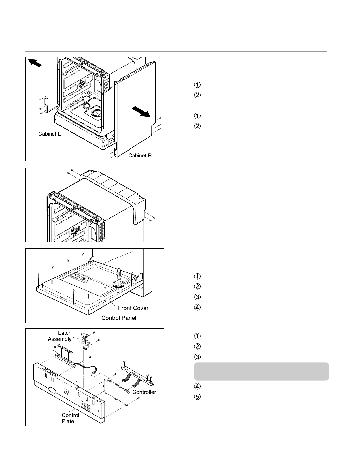
4. Cabinet-R/L
1) Cabinet-R
Remove front 3 screws.
Remove rear 3 screws.
2) Cabinet-L
Remove front 3 screws.
Remove rear 3 screws.
5. Balance weight
1) Remove side 4 screws.
2) Lift the balance weight.
6. Door Assembly
1) Front Cover
Open the door.
Remove 4 screws(long Type, stainless).
Remove 6 screws(stainless).
Close the door slowly and remove front
cover downwards.
2) Control Panel Assembly
Open the door.
Remove 2 screws(stainless).
Remove wire connection.
Be sure the wiring should not be
changed in reassembling.
Remove 3 screws for Latch assembly
Remove 7 screws for Controller.
- 13 -
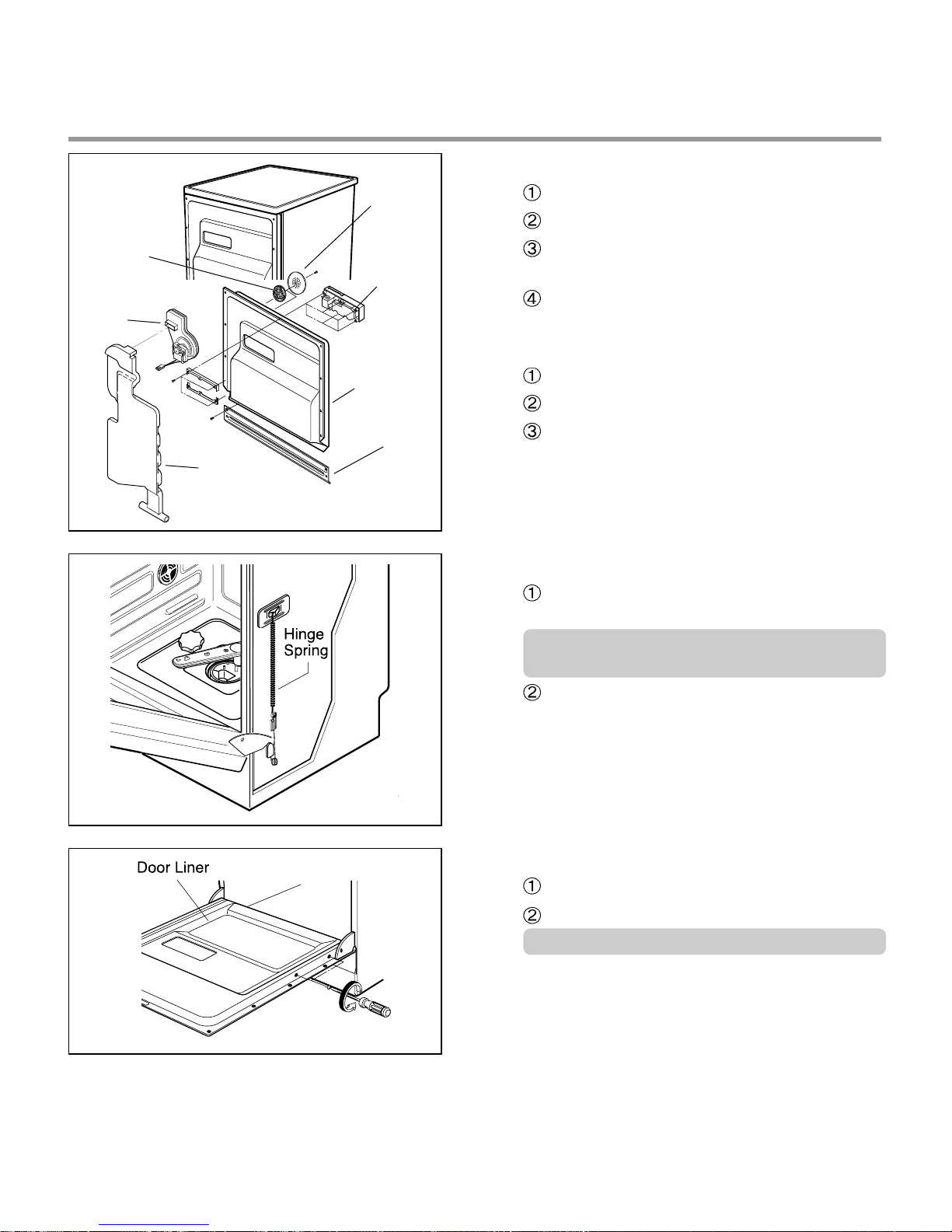
3) Fan(Not on all models)
Inner
Cover
Fan
Air Duct
Out
Cover
Detergent
Dispenser
Door Liner
Door Bracket
Open the door.
Remove the wire connections.
Remove the outer cover by removing 1
screw.
Remove 2 fixing screws inside and turn
the Inner Cover counterclockwise.
4) Detergent Dispenser
Close the door.
Remove the wire connections.
Remove 6 screws with brackets.
5) Door Spring (Right & Left)
Push the Spring upwards and take it off
from the Frame.
Be careful not to be injured by the sharp
edge of Tub.
Take the Hinge Link off from the Hinge.
6) Door Liner
Open the door.
Remove 4 screws.
Do not use other screws for assembling.
- 14 -
 Loading...