

Page 1
ENGLISH
19
BEFORE YOU BEGIN
Read these instructions completely and
carefully .
NOTES TO INSTALLER:
• Read all instructions contained in these
installation instructions before installing the
cooktop.
• Remove all packing material before connecting
the electrical supply to the cooktop.
• Observe all governing codes and ordinances.
• Only certain cooktop models may be installed
over certain built-in electric oven models.
• Be sure to leave these instructions with the
consumer.
NOTE TO CONSUMER:
Keep this User’s Guide and Installation Instructions
for future reference.
NOTE: This appliance must be properly
grounded.
Damage caused by failure to follow these
instructions is not covered by the cooktop
warranty.
UNPACKING THE COOKTOP
Unpack and visually inspect the cooktop for any
damage or missing components.
Be sure the bottle of cleaner and conditioner
packed in the literature bag is left where the
user can find it easily. It is important that the
ceramic-glass cooktop be pretreated before
use. See CARE AND CLEANING.
INST ALLATION INSTRUCTIONS AND SERVICE MUST BE PERFORMED BY A QUALIFIED
INST ALLER.
IMPORT ANT: SA VE THESE INSTRUCTIONS FOR LOCAL ELECTRICAL INSPECTOR’S USE.
READ AND SA VE THESE INSTRUCTIONS FOR FUTURE REFERENCE.
Page 2
20
TECHNICAL SPECIFICATIONS
COOKTOP DIMENSIONS
Width 30-27/32”(783 mm)
Depth 21-1/2”(546 mm)
Height 4
”
(101.6 mm)
COOKING ZONES
Position Diameter Power
Front Left 6”(152 mm) 1200 W
Front Right 9
”/6”
(229/152 mm) 3000/1400 W
Rear Left 8
”/5”
(203/127 mm) 1900/950 W
Rear Right 6
”
(152 mm) 100 W (Warm)
Center 7
”
(178 mm) 1500 W
COUNTERTOP CUTOUT
DIMENSIONS
Width 29-3/8”(746 mm)
Depth 20-1/4” (515 mm)
ELECTRICAL SPECIFICATIONS
Connection voltage:
240/208 VAC 60 Hz.
32.1A/27.9 A
Maximum connected power load:
7700 W/5800 W
COOKTOP DIMENSIONS
Width 36-11/16”(932 mm)
Depth 22
”
(559 mm)
Height 4
”
(101.6 mm)
COOKING ZONES
Position Diameter Power
Front Left 7”(178 mm) 1800 W (Bridge)
Front Right 9
”/6”
(229/152 mm) 3000/1400 W
Rear Left 7
”
(178 mm) 1800 W + 800 W (Bridge)
Rear Right 6
”
(152 mm) 100 W (Warm)
Center 12
”/9”/6”
(305/229/152 mm) 3000/2200/1100 W
COUNTERTOP CUTOUT
DIMENSIONS
Width 34-9/16”(878 mm)
Depth 20-3/8” (517 mm)
ELECTRICAL SPECIFICATIONS
Connection voltage:
240/208 VAC 60 Hz.
43.8A/38.0 A
Maximum connected power load:
10500 W/7900 W
LCE3081ST Radiant Cooktop
LCE3681ST Radiant Cooktop
Page 3
ENGLISH
21
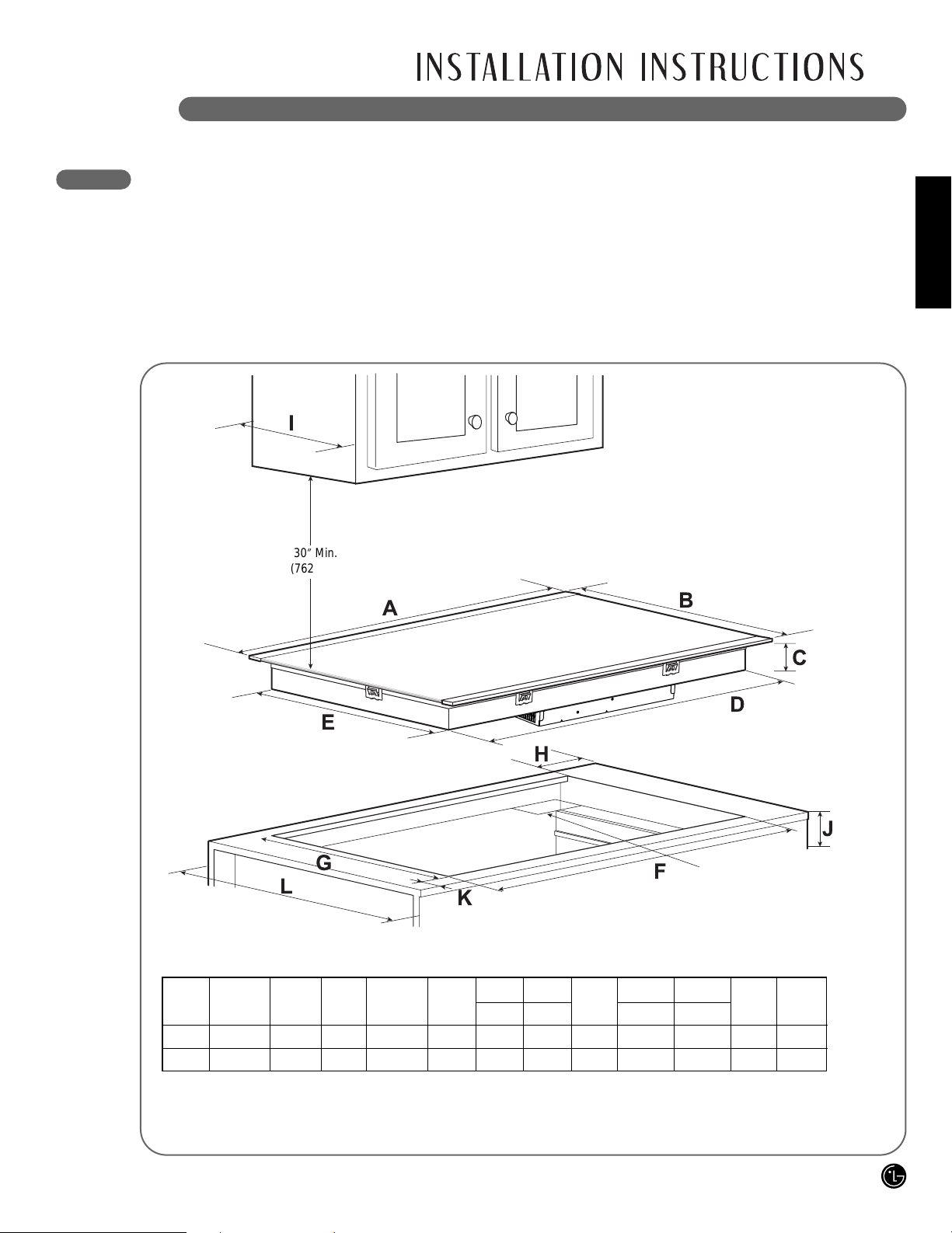
PREPARING THE INSTALLATION LOCATION
IMPORTANT INST ALLATION INFORMATION
• All electric cooktops run off a single phase, threewire or four-wire cable, 240/208 volt, 60 hertz,
AC-only electrical supply with ground.
• Minimum distance between cooktop and
overhead cabinetry is 30” (762 mm).
• Make sure the cabinets and wall coverings
around the cooktop can withstand the
temperatures (up to 93˚C [200˚F]) generated by
the cooktop.
A
B
I
C
D
H
E
F
G
K
L
J
30” Min.
(762 mm)
** Do not obstruct these areas!
All dimensions are stated in inches and millimeters (mm).
Allow 2” (50 mm) space below the armored cable opening to clear the electric cable and allow space
for installation of the junction box on the wall at the back of the cooktop.
30 inch Radiant Cooktop
LCE3081ST Radiant Cooktop
4" X 8" (102 mm x 203 mm)
opening to route armored
cable if panel is present.
Unit
Inch
mm
A
30-27/32
783
B
21-1/2
546
C
3-3/4
95
D
28-13/16
732
E
19-5/8
498
H
13/16
20
I
Max
13
330
K
2-1/2
64
L
24
610
F
Min
29-3/8
746
J
Min
5-23/32
145
G
Min
20-1/4
515
Page 4

22
DIMENSIONS AND CLEARANCES
F
G
I
K
L
H
J
CAUTION
To eliminate the risk of burns or fire by
reaching over heated surfaces, cabinet
storage space located above the cooktop
should be avoided. If cabinet storage is
provided, risk can be reduced by installing a
range hood that projects horizontally a
minimum of 5
” (127 mm) beyond the face of
the cabinets.
Overhead cabinet should not exceed a maximum
depth of 13” (330 mm).
Min. from edge of
cooktop to nearest
combustible wall
(either side of unit).
Empty space is needed underneath
the cooktop for installation purposes.
Approximate location of junction box.
12”
(305 mm)
10”
(254 mm)
18”
(457 mm)
36” Min
(914 mm)
24”
(610 mm)
Min. recommended
distance between
rear edge of cutout
and nearest
combustible
surface.
Model H K
LCE3081ST 3-3/4” (95 mm) 2-1/2” (64 mm)
Page 5

ENGLISH
23
PREPARING THE INSTALLATION LOCATION
IMPORTANT INST ALLATION INFORMATION
• All electric cooktops run off a single phase, threewire or four-wire cable, 240/208 volt, 60 hertz,
AC-only electrical supply with ground.
• Minimum distance between cooktop and
overhead cabinetry is 30” (762 mm).
• Make sure the cabinets and wall coverings
around the cooktop can withstand the
temperatures (up to 93˚C [200˚F]) generated by
the cooktop.
A
B
I
C
D
H
E
F
G
K
L
J
30” Min.
(762 mm)
** Do not obstruct these areas!
All dimensions are stated in inches and millimeters (mm).
Allow 2” (50 mm) space below the armored cable opening to clear the electric cable and allow space
for installation of the junction box on the wall at the back of the cooktop.
36 inch Radiant Cooktop
LCE3681ST Radiant Cooktop
4" X 8" (102 mm x 203 mm)
opening to route armored
cable if panel is present.
Unit
Inch
mm
A
36-11/16
932
B
22
559
C
3-3/4
95
D
33-27/32
860
E
19-25/32
502
H
13/16
20
I
Max
13
330
K
2-1/2
64
L
24
610
F
Min
34-9/16
878
J
Min
5-23/32
145
G
Min
20-3/8
517
Page 6

24
DIMENSIONS AND CLEARANCES
F
G
I
K
L
H
J
CAUTION
To eliminate the risk of burns or fire by
reaching over heated surfaces, cabinet
storage space located above the cooktop
should be avoided. If cabinet storage is
provided, risk can be reduced by installing a
range hood that projects horizontally a
minimum of 5” (127 mm) beyond the face of
the cabinets.
Model H K
LCE3681ST 3-3/4” (95 mm) 2-1/2” (64 mm)
Overhead cabinet should not exceed a maximum
depth of 13” (330 mm).
Min. from edge of
cooktop to nearest
combustible wall
(either side of unit).
Empty space is needed underneath
the cooktop for installation purposes.
Approximate location of junction box.
12”
(305 mm)
10”
(254 mm)
18”
(457 mm)
36” Min
(914 mm)
24”
(610 mm)
Min. recommended
distance between
rear edge of cutout
and nearest
combustible
surface.
Page 7

ENGLISH
25
ELECTRICAL CONNECTIONS
IMPORTANT SAFETY INSTRUCTIONS
• Be sure your cooktop is installed and grounded
properly by a qualified installer or service
technician.
• This cooktop must be electrically grounded in
accordance with local codes or, in their absence,
with the National Electrical Code ANSI/NFPA No.
70, latest edition in the United States.
PROVIDING THE ELECTRICAL CONNECTION
Install the junction box under the cabinet and run
120/240 or 120/208 volt, AC wire from the main
circuit panel.
NOTE: DO NOT connect the wire to the circuit
panel at this time.
ELECTRICAL REQUIREMENTS
Observe all governing codes and local
ordinances.
A 3-wire or 4-wire single-phase 120/240 or
120/208 volt, 60 Hz AC-only electrical supply is
required on a separate circuit fused on both
sides of the line (time-delay fuse or circuit
breaker is recommended). DO NOT fuse
neutral. The fuse size must not exceed the
circuit rating of the appliance specified on the
nameplate.
36” Radiant cooktop can consume up to
10,500W at 240 VAC. A 50 Amp circuit breaker
with wire guage #8 AWG must be used.
30” Radiant cooktop can consume up to 7700W
at 240 VAC. A 40 Amp circuit breaker with wire
guage #8 AWG must be used.
NOTE: Wire sizes and connections must
conform with the fuse size and rating of the
appliance in accordance with the National
Electrical Code ANSI/NFPA No. 70, latest
edition, and local codes and ordinances.
The appliance should be connected to the fused
disconnect (or circuit breaker) box through
flexible armored or nonmetallic sheathed cable.
The flexible armored cable extending from this
appliance should be connected directly to the
grounded junction box. The junction box should
be located as shown on page 21 or 23 with as
much slack as possible remaining in the cable
between the box and the appliance, so it can be
moved if servicing is ever necessary.
A suitable strain relief must be provided to
attach the flexible armored cable to the junction
box.
WARNING
The electrical power to the cooktop must be
shut off while line connections are being
made. Failure to do so could result in serious
injury or death.
WARNING
An extension cord must not be used with this
appliance. Such use may result in a fire,
electrical shock, or other personal injury.
Page 8

26
ELECTRICAL CONNECTIONS (cont.)
ELECTRICAL CONNECTION
Connect the flexible armored cable that extends
from the surface unit to the junction box using a
suitable strain relief at the point the armored cable
enters the junction box. Then make the electrical
connection as follows.
Electrical ground is required on this appliance.
This appliance is manufactured with a supply wire
and a frame connected green or bare copper
grounding wire.
NOTE TO ELECTRICIAN:
The armored cable leads supplied with the
appliance are UL-listed for connection to larger
gauge household wiring. The insulation of the leads
is rated at temperatures much higher than the
temperature rating of household wiring. The
current-carrying capacity of the conductor wire is
governed by the temperature rating of the
insulation around the wire, rather than the wire
gauge alone.
Observe all governing codes and local
ordinances.
Disconnect the power supply.
At the circuit breaker box, fuse box or junction
box, connect appliance and power supply cable
wires as shown.
WARNING
DO NOT ground to a gas supply pipe. DO
NOT connect to electrical power supply until
appliance is permanently grounded.
Connect the ground wire before turning on
the power.
WARNING
This appliance is equipped with a copper
conductor flexible cable. If connection is
made to aluminum house wiring, use only
special connectors which are approved for
joining copper and aluminum wires in
accordance with the National Electrical Code
and local codes and ordinances. Improper
connection of aluminum house wiring to
copper leads can result in a short circuit or
fire. Follow the connector manufacturer’s
recommended procedure closely.
WARNING
You may not ground the cooktop through the
neutral (white) wire if cooktop is used in a
new branch circuit installation (1996 NEC),
mobile home, recreational vehicle, or where
local codes do not permit grounding to the
neutral (white) wire. When grounding to the
neutral (white) wire is prohibited, you must
use a 4-wire power supply cable. Failure to
heed this warning may result in electrocution
or other serious personal injury.
WHERE LOCAL CODES PERMIT CONNECTING THE APPLIANCE-GROUNDING CONDUCTOR
TO THE NEUTRAL (WHITE) WIRE
3-WIRE GROUNDED JUNCTION BOX
Cable from power supply
Black
wires
Red
wires
Junction box
UL-listed conduit
connector
Cable from cooktop
Green wire (ground)
White wire
(neutral)
Page 9

ENGLISH
27
ELECTRICAL CONNECTIONS (cont.)
Observe all governing codes and local
ordinances.
Disconnect the power supply.
At the circuit breaker box, fuse box or junction
box, connect appliance and power supply cable
wires as shown.
WARNING
If connecting to a 4-wire power supply cable
electrical system, the appliance frame
connected ground wire MUST NOT be
connected to the neutral wire of the 4-wire
electrical system.
IF COOKTOP IS USED IN A NEW BRANCH CIRCUIT INST ALLATION (1996 NEC), MOBILE
HOME, RECREA TIONAL VEHICLE, OR WHERE LOCAL CODES DO NOT PERMIT GROUNDING
TO THE NEUTRAL (WHITE) WIRE
4-WIRE GROUNDED JUNCTION BOX
Cable from power supply
Black
wires
White wire
(no connection)
Red
wires
Junction box
UL-listed conduit
connector
Cable from cooktop
Green wire (ground)
Ground
Wire
COOKTOP INSTALLATION
Visually inspect the cooktop for damage.
Make sure all cooktop screws are tight
(see below for locations).
Carefully lower the cooktop into the counter- top
cutout, making sure not to trap any wires.
NOTE: Do not use caulking compound. The
cooktop must be removable, should service be
required.
Screws
Page 10

28
COOKTOP INSTALLATION (cont.)
FINAL CHECK
Perform a final operational check of the cooktop,
making sure the cooktop powers on properly and
that each Cooking Zone operates correctly. Refer
to the Operating Instructions in this guide for
details.
MODEL AND SERIAL NUMBER LOCA TION
The model and serial numbers are located on a
plate on the bottom of the cooktop. Please record
them in this guide; you will need them for warranty
registration.
CAUTION
Do not touch cooktop glass or Cooking
Zones. They may be hot enough to cause
burns.
Install the retainer brackets to the bottom of the
cooktop; then snug the bolts against the bottom
of the countertop as shown.
NOTE: The retainer brackets MUST be installed
to meet local codes or, in their absence, with
the National Electrical Code ANSI/NFPA No. 70,
latest edition.
Retainer brackets
Cooktop
Bolt
Retainer brackets
Countertop
Preferred installation
Retainer brackets
Alternative installation
Retainer brackets
Front
Front
Rear
Rear
Alternative installation
LCE3081ST Radiant Cooktop
LCE3081ST / LCE3681ST Radiant Cooktop
LCE3681ST Radiant Cooktop
 Loading...