

LG LCC-K1000 Owner’s Manual

Dynamic Controller
Owner’s Manual
MODEL : LCC-K1000
Before installing and using the product, please read this owner's
manual carefully and retain for future reference.
LCC-K1000_AABBLLG_ENG_75N 7/19/06 1:50 PM Page 1
2
This lightning flash with arrowhead symbol
within an equilateral triangle is intended to
alert the user to the presence of uninsulated dangerous voltage within the product’s
enclosure that may be of sufficient magnitude to constitute a risk of electric shock to
persons.
The exclamation point within an equilateral
triangle is intended to alert the user to the
presence of important operating and maintenance (servicing) instructions in the literature accompanying the product.
WARNING: Do not install this equipment in a confined space such as a bookcase or similar unit.
CAUTION: The apparatus should not be exposed to
water (dripping or splashing) and no objects filled
with liquids, such as vases, should be placed on the
apparatus.
FCC WARNING: This equipment may generate or
use radio frequency energy. Changes or modifications to this equipment may cause harmful interference unless the modifications are expressly
approved in the instruction manual. The user could
lose the authority to operate this equipment if an
unauthorized change or modification is made.
This product is manufactured to comply
with the radio interference requirements of
EEC DIRECTIVE 89/336/EEC, 93/68/EEC
and 73/23/EEC.
Regulatory Notices For U.S.A
This equipment has been tested and found to comply
with the limits for a Class A digital device,pursuant to
Part 15 of the FCC Rules. These limits are designed to
provide reasonable protection against harmful interference when the equipment is operated in a commercial
environment.
This equipment generates,uses,and can radiate radio
frequency energy and,if not installed and used in
accordance with the instruction manual,may cause
harmful interference to radio communications.Operation
of this equipment in a residential area is likely to cause
harmful interference in which case the user will be
required to correct the interference at his own expense.
•
A suitable conduit entries, knock-outs or glands shall
be provided in the cable entries of this product in the
end user.
•
Caution: Danger of explosion if battery is incorrectly
replaced.Replaced only with the same or equivalent
type recommended by the manufacturer. Dispose of
used batteries according to the manufacturer ’s
instructions.
•
Holes in metal, through which insulated wires
pass,shall have smooth well rounded surfaces or
shall be provided with brushings.
WARNING:
This is a class A product. In a domestic
environment this product may cause radio interference
in which case the user may be required to take adequate measures.
WARNING: Wiring methods shall be in accordance
with the National Electric Code, ANSI/NFPA 70.
SERIAL NUMBER:
You can find the serial number on the back of the
unit. This number is unique to this unit and not available to others. You should record requested information here and retain this guide as a permanent record
of your purchase.
Model No. ______________________________
Serial No. ______________________________
CAUTION: TO REDUCE THE RISK
OF ELECTRIC SHOCK
DO NOT REMOVE COVER (OR BACK)
NO USER-SERVICEABLE PARTS INSIDE
REFER SERVICING TO QUALIFIED SERVICE
PERSONNEL.
CAUTION
RISK OF ELECTRIC SHOCK
DO NOT OPEN
LCC-K1000_AABBLLG_ENG_75N 7/19/06 1:50 PM Page 2
3
1. Read these instructions. - All these safety and operating
instructions should be read before the product is operated.
2. Keep these instructions. - The safety, operating and use
instructions should be retained for future reference.
3. Heed all warnings. - All warnings on the product and in
the operating instructions should be adhered to.
4. Follow all instructions. - All operating and use instruc-
tions should be followed.
5. Do not use this product near water. – For example:
near a bath tub, wash bowl, kitchen sink, laundry tub, in a
wet basement; or near a swimming pool; and other areas
located near water.
6. Clean only with dry cloth. – Unplug this product from the
wall outlet before cleaning. Do not use liquid cleaners.
7.
Do not block any ventilation openings. Install in accordance with the manufacturer’s instructions. -
Slots and
openings in the cabinet are provided for ventilation and to
ensure reliable operation of the product and to protect it
from over- heating. The openings should never be
blocked by placing the product on a bed, sofa, rug or other
similar surface. This product should not be placed in a
built-in installation such as a bookcase or rack unless
proper ventilation is provided or the manufacturer’s
instructions have been adhered to.
8. Do not install near any heat sources such as radiators, heat registers, stoves, or other apparatus
(including amplifiers) that produce heat.
9. D
o not defeat the safety purpose of the polarized or
grounding-type plug. A polarized plug has two
blades
with one wider than the other. A grounding
type plug
has two blades and a third grounding prong. The wide
blade or the third prong are provided for your safety. If
the provided plug does not fit into your outlet, consult
an electrician for replacement of the obsolete outlet.
10. Protect the power cord from being walked on or
pinched particularly at plugs, convenience receptacles, and the point where they exit from the product.
11. Only use attachments/accessories specified by the
manufacturer.
12. Use only with the cart, stand, tripod, bracket, or
table specified by the manufacturer, or sold with
apparatus. When a cart is used, use caution when
moving the cart/product combination to avoid injury
from tip-over.
13. Unplug this product during lightning storms or
when unused for long periods of time.
14.
Refer all servicing to qualified service personnel.
Servicing is required when the product has been
damaged in any way, such as power-supply cord or
plug is damaged, liquid has been spilled or objects
have fallen into the product, the product has been
exposed to rain or moisture, does not operate normally, or has been dropped.
IMPORTANT SAFETY INSTRUCTIONS
CAUTION:
PLEASE READ AND OBSERVE ALL WARNINGS AND INSTRUCTIONS IN THIS OWNER’S MANUAL. AND
THOSE MARKED ON THE PRODUCT. RETAIN THIS BOOKLET FOR FUTURE REFERENCE.
This product has been designed and manufactured to assure personal safety. Improper use can result in electric shock or
fire hazard. The safeguards incorporated in this product will protect you if you observe the following procedures for installation, use, and servicing.
This product does not contain any parts that can be repaired by the user.
DO NOT REMOVE THE CABINET COVER, OR YOU MAY BE EXPOSED TO DANGEROUS VOLTAGE. REFER SERVICING TO QUALIFIED SERVICE PERSONNEL ONLY.
LCC-K1000_AABBLLG_ENG_75N 7/19/06 1:50 PM Page 3

4
Contents
Introduction . . . . . . . . . . . . . . . . . . . . . . . . . . . .4-7
Contents . . . . . . . . . . . . . . . . . . . . . . . . . . . . . . . .4
About Dynamic Controller . . . . . . . . . . . . . . . . .5
Features . . . . . . . . . . . . . . . . . . . . . . . . . . . . . .5
Identification of the Controller . . . . . . . . . . . . .6-7
Connections . . . . . . . . . . . . . . . . . . . . . . . . . . . . .8
Precautions . . . . . . . . . . . . . . . . . . . . . . . . . . . . . .8
RS-485 Connection . . . . . . . . . . . . . . . . . . . . . . . .8
Setup Menu . . . . . . . . . . . . . . . . . . . . . . . . . . .9-21
Setup Menu Overview . . . . . . . . . . . . . . . . . . . . . .9
Key Functions on the Set Up . . . . . . . . . . . . . . . .10
Operation Start (Login) . . . . . . . . . . . . . . . . . . . .10
Communication Settings . . . . . . . . . . . . . . . . . . .11
List of the communication settings . . . . . . . . .11
Operation . . . . . . . . . . . . . . . . . . . . . . . . . . . .11
Protocol Setting . . . . . . . . . . . . . . . . . . . . . . .11
Communication Speed (Baud Rate) Setting . .11
Parity bit / Data Bits Setting / Stop Bit Setting .11
Preset Settings . . . . . . . . . . . . . . . . . . . . . . . . . .12
To register preset positions . . . . . . . . . . . . . .12
Changing to Picture at Preset Position . . . . . .12
To tour the preset positions . . . . . . . . . . . . . .13
To group the preset positions . . . . . . . . . . . . .13
To tour the group . . . . . . . . . . . . . . . . . . . . . .14
To clear the preset position . . . . . . . . . . . . . .14
To clear all preset position . . . . . . . . . . . . . . .15
To clear a group . . . . . . . . . . . . . . . . . . . . . . .15
To set Alarm Input . . . . . . . . . . . . . . . . . . . . .16
To set Alarm Output . . . . . . . . . . . . . . . . . . . .16
Auto Pan Setup and Activation . . . . . . . . . . . . . . .17
To set the points of auto pan . . . . . . . . . . . . .17
To activate auto pan . . . . . . . . . . . . . . . . . . . .17
Pattern Setup and Activation . . . . . . . . . . . . . . . .18
To record the pattern . . . . . . . . . . . . . . . . . . .18
Pattern Play . . . . . . . . . . . . . . . . . . . . . . . . . .18
Privacy Setup . . . . . . . . . . . . . . . . . . . . . . . . . . .19
To register a new privacy zone . . . . . . . . . . . .19
To display or disappear privacy zone . . . . . . .19
Configuration Settings . . . . . . . . . . . . . . . . . . . . .20
Operation . . . . . . . . . . . . . . . . . . . . . . . . . . . .20
Focus Speed Setting . . . . . . . . . . . . . . . . . . .20
PTZ Home Position . . . . . . . . . . . . . . . . . . . .20
PTZ Position Reset . . . . . . . . . . . . . . . . . . . .20
Remote PTZ Reset . . . . . . . . . . . . . . . . . . . .21
Auto Key Lock Setting . . . . . . . . . . . . . . . . . .21
To Change the User Password . . . . . . . . . . . .21
Factory Reset . . . . . . . . . . . . . . . . . . . . . . . .21
About LCC-K1000 . . . . . . . . . . . . . . . . . . . . .21
Camera Control Function . . . . . . . . . . . . . . . . . .22
Pan/Tilt Control . . . . . . . . . . . . . . . . . . . . . . . . . .22
Lens Control . . . . . . . . . . . . . . . . . . . . . . . . . . . .22
Reference . . . . . . . . . . . . . . . . . . . . . . . . . . . . . .23
Specifications . . . . . . . . . . . . . . . . . . . . . . . . . . .23
Introduction
LCC-K1000_AABBLLG_ENG_75N 7/19/06 1:50 PM Page 4
5
About Dynamic Controller
This controller is the brand of Dome Camera Control Keyboard of LG in a surveillance system.You can operate
this system very easily and conveniently because of design structure based on biotechnology and various
functions for users. In addition, the controller can control using the whole functions of the LG Dome Camera
such as zoom, focus and Pan/Tilt heads.
Features
The Dynamic Controller offers the following functions:
xx
User-friendly Graphic User Interface
xx
Compatible with LG Dome Cameras and Zoom Cameras
xx
Joystick Control of PTZ Functions
xx
Program Preset Position up to 128 and Pattern Control
(Memorize continuous series of Zoom In/Out, Pan/Tilt)
xx
Control Privacy Zone Masking
xx
Easy Firmware Upgrade
(Please contact authorized service center or where you purchased to upgrade the firmware.)
xx
Ergonomic Design
Note: The Dynamic Controller is not provided with functions to control the audio signal. Audio communication
is not possible, regardless of whether audio boards are installed in the receiver.
LCC-K1000_AABBLLG_ENG_75N 7/19/06 1:50 PM Page 5
6
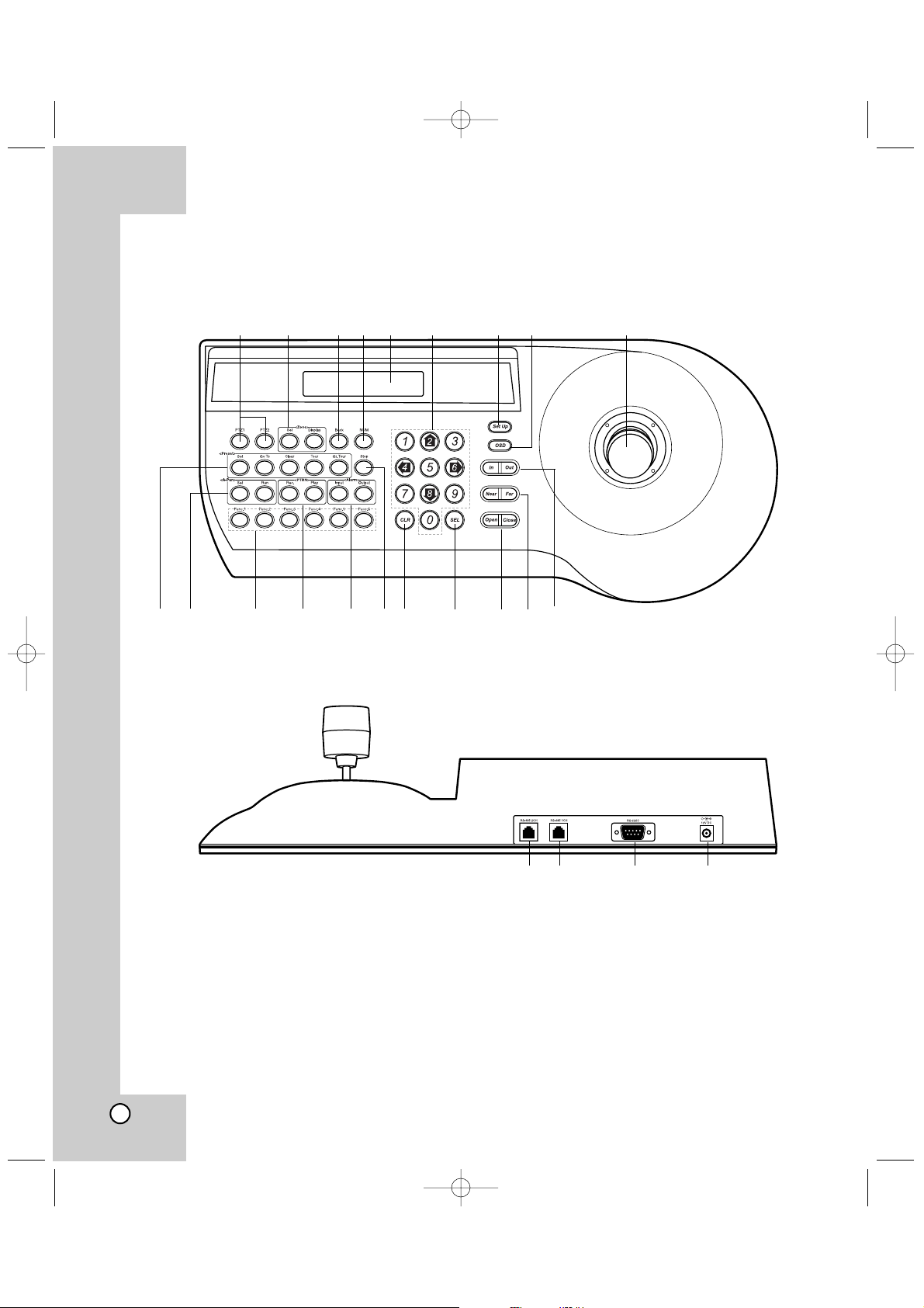
Identification of the Controller
123456 78 9
q; qa qs qd qf qg qh qj qk ql w;
wa ws wd wf
LCC-K1000_AABBLLG_ENG_75N 7/19/06 1:50 PM Page 6
1 PTZ1 / PTZ2 Button
Press to select a camera connected to the controller’s data ports.
Press PTZ1 to control the camera connected to
RS-485 1CH port.
Press PTZ2 to control the camera connected to
RS-485 2CH port.
2 Zone Buttons
For details, see page 19.
3 Back Buttons
This button is used to return to the previous menu
or mode.
4 NUM Button
Press this button to change to numeric entering
mode on the menu.
5 Display Window
Displays function menus, numeric input, and
system status.
6 Numeric (0-9) and Arrow (left/right/up/down)
Buttons
Selects an option in the menu.
These buttons are used for numeric input of preset numbers or for executing each parameter on
the Controller’s menu.
7 Set Up Button
Opens controller’s main Set Up menu in the display window.
8 OSD Button
Opens or closes the Camera’s Setup menu on
the screen.
9 Joystick Controller
This joystick manually operates the Pan/Tilt Head
and turning the joystick head to the right or left
will zoom or widen the image. (The zooming level
will go up or down.)
q; Preset Buttons
For details, see pages 12-14.
qa A-Pan (Auto-Pan) Buttons
For details, see page 17.
qs Func.1
Press the button to switch the LG Multix protocol
or LG Old protocol.
Func.6
If you use LG Multix Protocol, press the button to
change the AF Mode. (Auto or Manual) When the
AF Mode is PushAuto mode, press and hold the
button to activate the Auto Focusing and release
the button to inactivate the Auto Focus.
Func.2-5
These buttons are not assigned.
qd PTRN (Pattern) Buttons
For details, see page 18.
qf Alarm Buttons
For details, see pages 16.
qg Stop Button
Stops the playback of recorded images or pattern
playing back.
qh CLR (CLEAR) Button
Clears the parameter entered with numeric buttons.
qj SEL Button
This button is used to execute the currently
highlighted setting in the Setup menu.
qk Open/Close Buttons
The lens iris is adjusted by pressing the OPEN or
CLOSE button.
ql Near/Far Buttons
These buttons are used to adjust the lens focus
of cameras equipped with the specified lens.
w; In/Out Buttons
These buttons are used to zoom the camera
image In (TELE) and Out (WIDE).
wa RS-485 Data Ports (CH 2)
These ports are used to exchange control data
with the connected camera via the RS-485 cable.
To control the camera connected to this port,
press PTZ2 button on the controller.
ws RS-485 Data Ports (CH 1)
These ports are used to exchange control data
with the connected camera via the RS-485 cable.
To control the camera connected to this port,
press PTZ1 button on the controller.
wd RS-232C Port
Is used only for authorized service purposes.
wf DC 12V Input Jack (12V DC)
Connect a DC 12V Certified/Listed, class 2 power
supply only to the DC input terminal on the back
of the controller.
7
LCC-K1000_AABBLLG_ENG_75N 7/19/06 1:50 PM Page 7
8
Precautions
• The connections should be made by qualified
service personnel or system installers in accordance with all local codes.
• DC 12V can be used.
RS-485 Connection
Use the cable that is described below for RS-485 site
communication.
• Shielded, twisted pair cable
• Low impedance
•Wire gauge size is thicker than AWG #22
(0.33 mm 2).
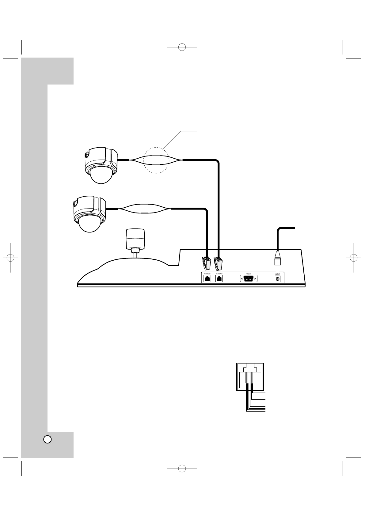
Connections
LCC-K1000_AABBLLG_ENG_75N 7/19/06 1:50 PM Page 8
Camera 1
RS-485 Connection
5: TRX+
6: TRX-
Camera 2
RJ11 Cable (Supplied)
DC 12V cable
for Controller
6 TRX5 TRX+
1-4 GND
 Loading...