

LG LB-F3660HL, LB-F3660CL User Manual

Ceiling Duct Type Air Conditioner
SVC MANUAL(Exploded View)
MODEL : LB-F3660HL
LB-F3660CL
CAUTION
Before Servicing the unit, read the safety precautions in General SVC manual.
Only for authorized service personnel.
Internal Use Only
http://biz.lgservice.com
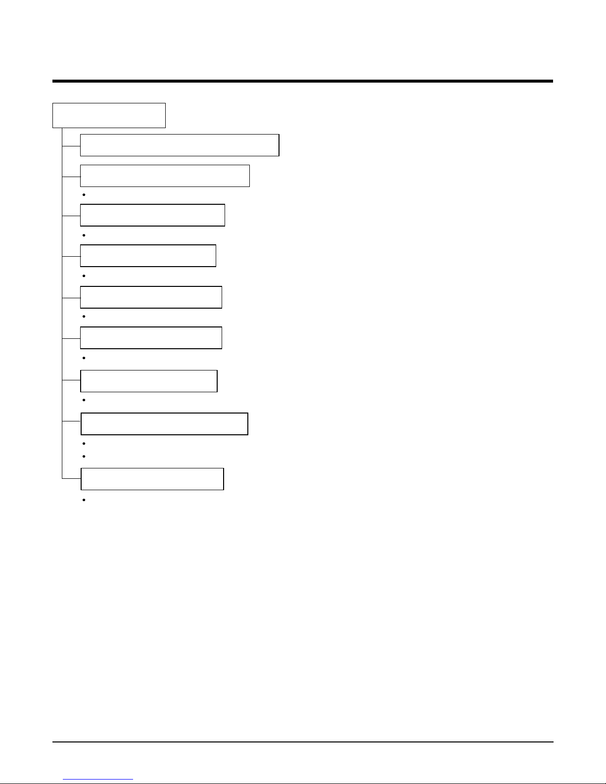
Contents
Functions 3
Product Specifications (Cooling & Heating) 5
Dimensions 6
Refrigeration Cycle Diagram 7
Wiring Diagram 9
Operation Details 11
Installation of Indoor, Outdoor Unit 14
Test Running 25
3-way Valve 27
Cycle Troubleshooting Guide 32
Electronic Parts Troubleshooting Guide 33
Electronic Control Device 36
Schematic Diagram 37
Exploded View 38
- 2 -
Copyright ©2008 LG Electronics. Inc. All right reserved.
Only for training and service purposes
LGE Internal Use Only
Functions
Room temperature sensor. (Thermistor)
Maintains the room temperature in accordance with the Setting Temp.
Indoor fan is delayed for 5 seconds at the starting.
Restarting is inhibited for approx. 3 minutes.
High, Med, Low
Intermittent operation of fan at low speed.
Both the indoor and outdoor fan stops during defrosting.
Hot start after defrost ends.
The indoor fan stops until the evaporator piping temperature will be reached at 28°C
Indoor Unit
Operation ON/OFF by Remote controller
Sensing the Room Temperature
Room temperature control
Starting Current Control
Time Delay Safety Control
Indoor Fan Speed Control
Soft Dry Operation Mode
Deice (defrost) control (Heating)
Hot-start Control (Heating)
- 3 -
Copyright ©2008 LG Electronics. Inc. All right reserved.
Only for training and service purposes
LGE Internal Use Only
- 4 -
Copyright ©2008 LG Electronics. Inc. All right reserved.
Only for training and service purposes
LGE Internal Use Only
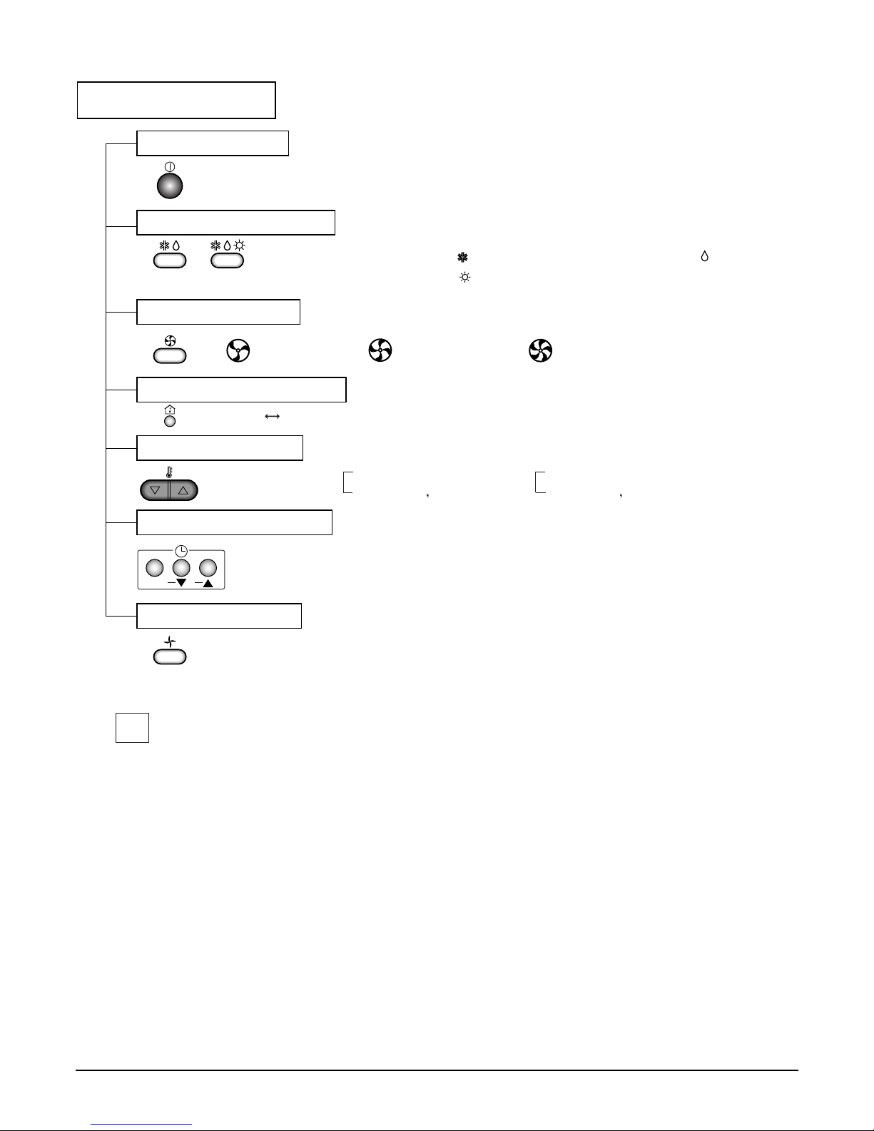
Remote Controller
Operation ON/OFF
Operation Mode Selection
Fan Speed Selection
Room Temperature Display
Temperature Setting
Setting the Time or Timer
(Cooling
model only)
(Heating
model only)
(Low) (Med) (High)
Cooling Operation Mode ( )
Heating Operation Mode ( )
Soft Dry Operation Mode ( )
Fan Operation Mode
HIMEDLO
Set
: High:39°C LOW:11°C
: Fan Operates without cooling & heating
Although the air conditioner is turned off by a power failure, it is restarted
automatically after a power resupply.
Cooling Heating
Down to 18°C
Up to 30°C
Down to 16°C
Up to 30°C
✔
- 5 -
Copyright ©2008 LG Electronics. Inc. All right reserved.
Only for training and service purposes
LGE Internal Use Only
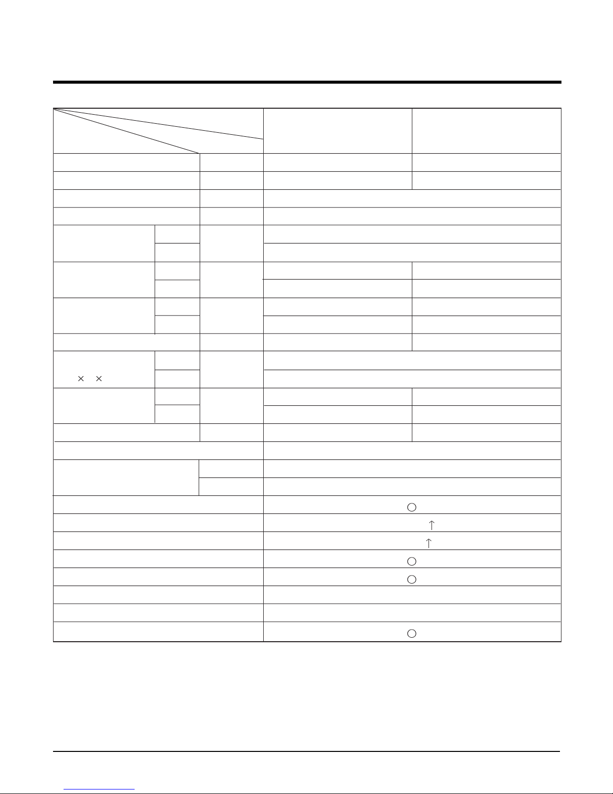
Product Specifications (Cooling & Heating)
Item
Cooling Capacity Btu/h(kcal/h) 36,000(9,073) 36,000(9,073)
Heating Capacity Btu/h(kcal/h) 36,000(9,073) -
Moisture Removal l/h 5.0
Power Source Ø, V, Hz 1, 220-240, 50
Indoor 37
Outdoor 58
Input Cooling 4,600 4,700
Heating 4,150 -
Running Current Cooling 23 23
Heating 21.5 -
E.E.R. Btu/h-W 7.83 7.66
Indoor 1,180 x 298 x 600
Outdoor 790 x 965 x 320
Indoor 46 46
Outdoor 81 78
Refrigerant (R-22) g 3.4 3.4
Remocon Type L.C.D
Liquid 3/8" (9.52)
Gas 5/8" (15.88)
Drain Hose
Connecting Wire 0.75mm
2
Main Power Cable 5.5mm
2
Time Delay Safety Function
Soft Dry
Fan Speed (Indoor) 3 (Hi, Med, Low)
Timer 24Hrs
Self-Diagnosis
Air Circulation
m3/min
Dimensions
(W H D)
Net. Weight
mm
kg
W
A
LB-F3660HL LB-F3660CL
Service Valve &
Connecting Tube
Model Name
Unit
- 6 -
Copyright ©2008 LG Electronics. Inc. All right reserved.
Only for training and service purposes
LGE Internal Use Only
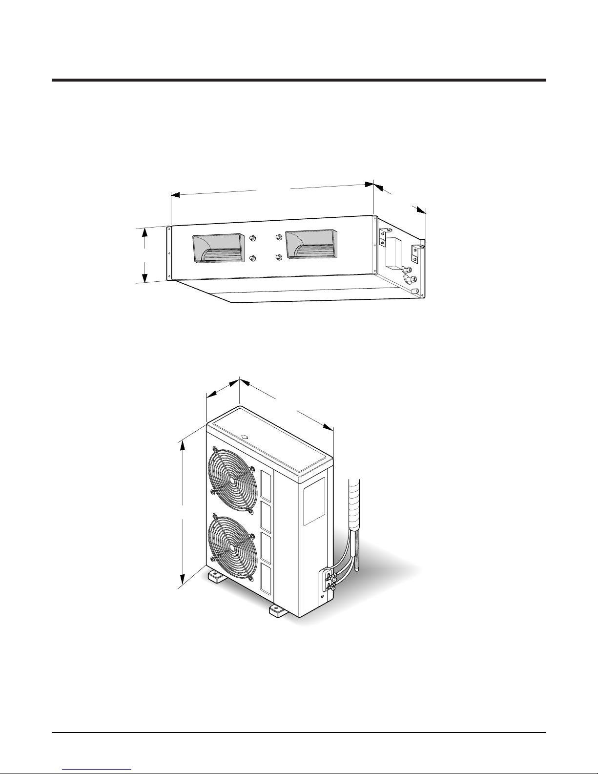
Dimensions
■ Model:LB-F3660HL/CL
(1) Indoor Unit
790
965
320
1180
600
298
(2) Outdoor Unit
- 7 -
Copyright ©2008 LG Electronics. Inc. All right reserved.
Only for training and service purposes
LGE Internal Use Only
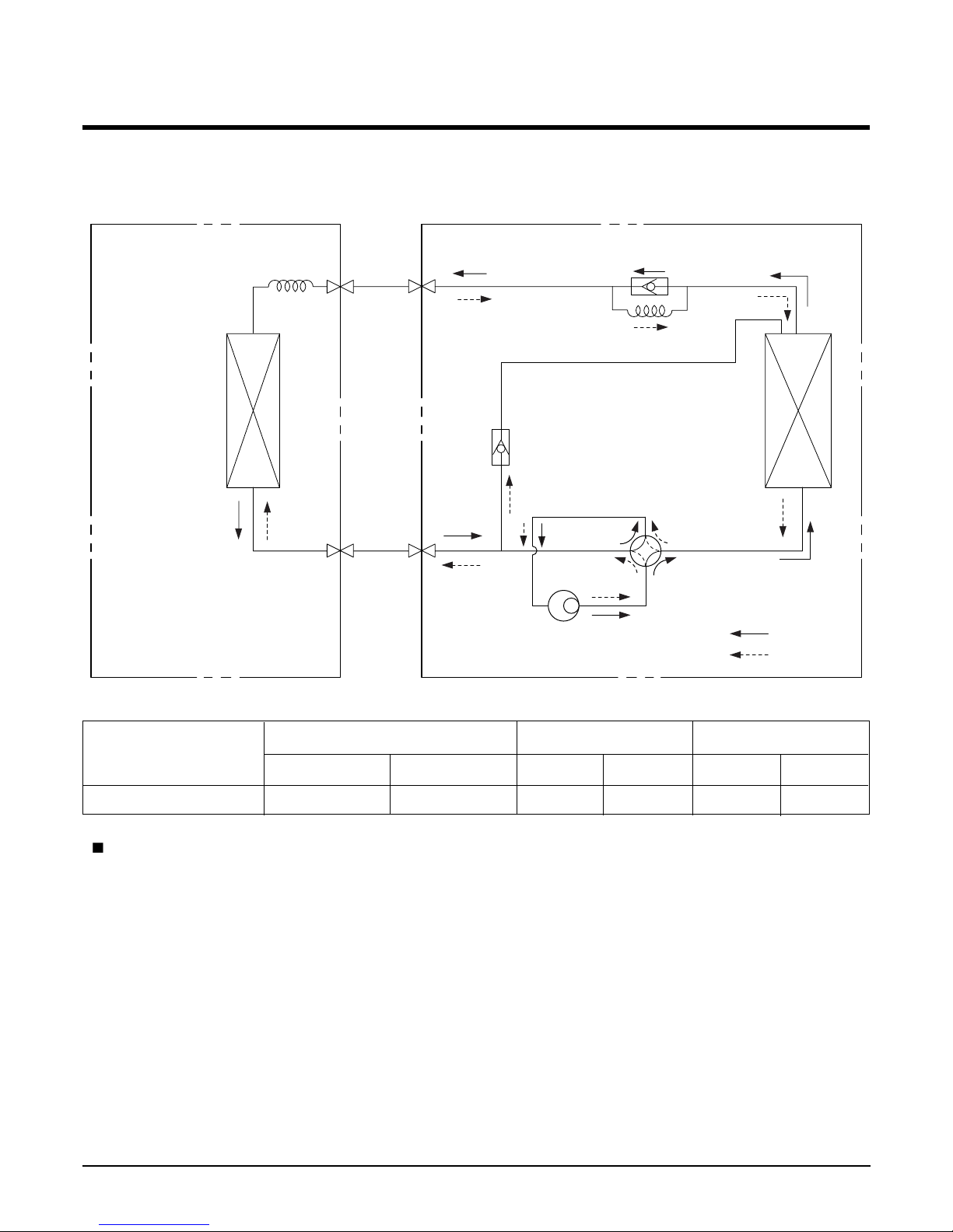
Refrigeration Cycle Diagram
■ LB-F3660HL
( Rated performance for refrigerant line length of: 5m)
For installation over rated distance, 70g of refrigerant should be added for each meter.
ex) When installed at a distance of 15m, 700g of refrigerant should be added.
(15-5) x 70g = 700g
Pipe size(Diameter: ø) Piping length(m) Elevation(m)
MODEL
Gas Liquid Rated Max. Rated Max.
LB-F3660HL 5/8" 3/8" 5 25 5 15
INDOOR UNIT OUTDOOR UNIT
HEAT
EXCHANGER
HEAT
EXCHANGER
COMPRESSOR
GAS SIDE
LIQUID SIDE
COOLING
HEATING
REVERSING
VALVE
CHECK VALVE
CAPILLARY TUBE
CAPILLARY TUBE
BY PATH CAPILLARY TUBE
- 8 -
Copyright ©2008 LG Electronics. Inc. All right reserved.
Only for training and service purposes
LGE Internal Use Only
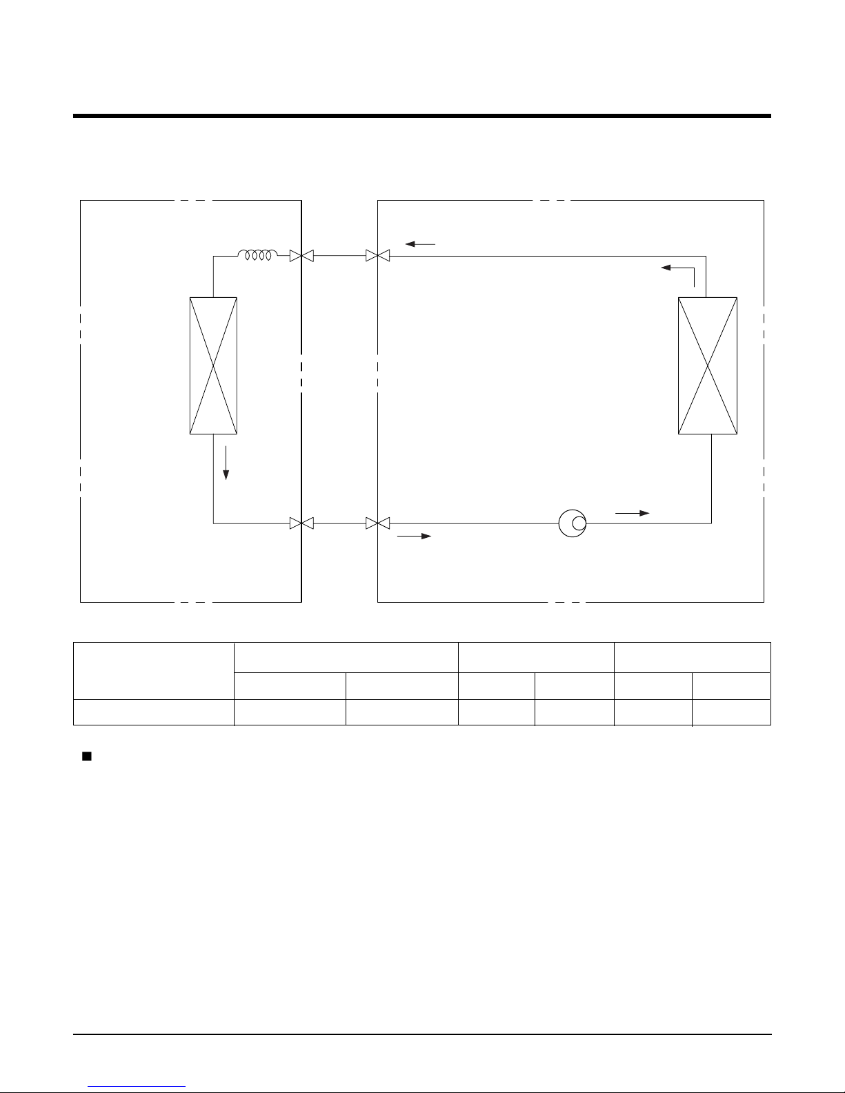
■ LB-F3660CL
( Rated performance for refrigerant line length of: 5m)
For installation over rated distance, 70g of refrigerant should be added for each meter.
ex) When installed at a distance of 15m, 700g of refrigerant should be added.
(15-5) x 70g = 700g
Pipe size(Diameter: ø) Piping length(m) Elevation(m)
MODEL
Gas Liquid Rated Max. Rated Max.
LB-F3660CL 5/8" 3/8" 5 25 5 15
INDOOR UNIT OUTDOOR UNIT
HEAT
EXCHANGER
(CONDENSER)
HEAT
EXCHANGER
(CONDENSER)
COMPRESSOR
GAS SIDE
LIQUID SIDE
CAPILLARY TUBE
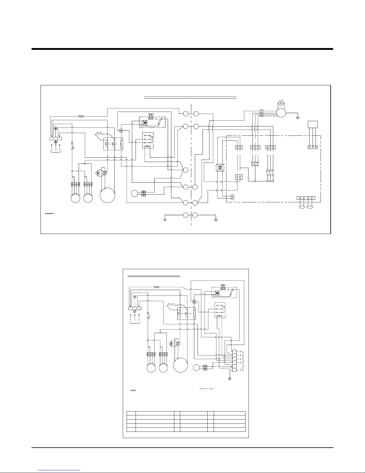
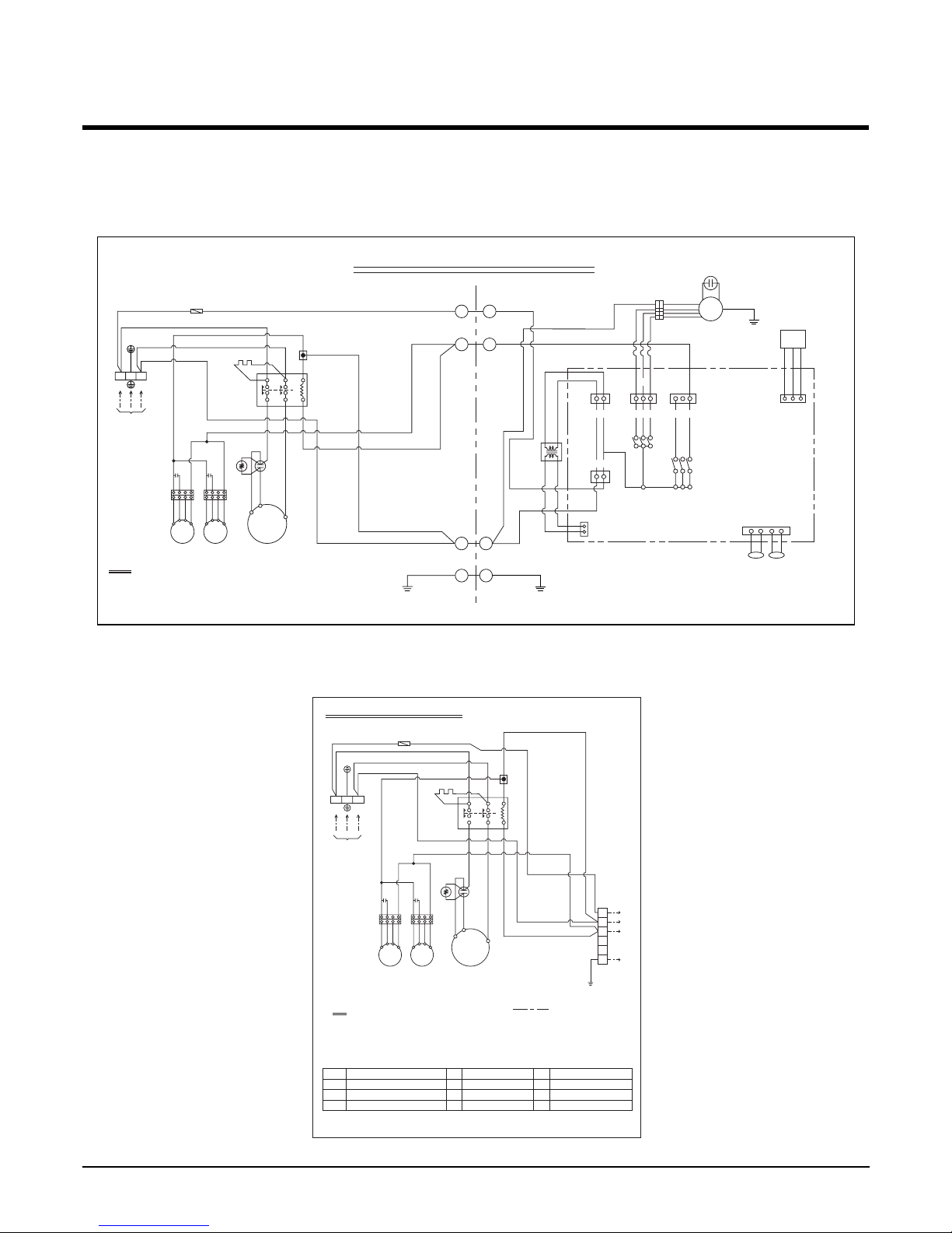
Wiring Diagram
■ Model: LB-F3660HL
(1) Indoor Unit
(2) Outdoor Unit
- 9 -
Copyright ©2008 LG Electronics. Inc. All right reserved.
Only for training and service purposes
LGE Internal Use Only
2
6
4
COi
GN/YL
FMi
TRANS
WH
BL
BK
GN/YLGN/YL
RD
OR
CN-TRANS2
PWB ASM
CN-POWER
CN-TRANS1
Hi Med Low
CN-MOTOR
RY-FAN
RY-4WAY
RY-COMP
CN-OUT
1
3
6
DC-12V
SIGNAL
GND
CN-REMO
INDOOR ELECTRIC CIRCUIT
INDOOR UNITOUTDOOR UNIT
(
RD
)
(
YL
)
(
BR
)
P/NO : 3854A20025F
4
5
3
2
78
1TM
220-240V
1Ø, 50Hz
POWER SUPPLY
BK
63H2
52C
L1T1L2
T2
A2
A1
BK
WH
BK
52F1
12
34
56
TNS
NO
C TH
NC
D.P
WH
BK
BLBK
WH
T/B1
F1
BK
WH
WH
WH
BR
Co
OR YLCoOR
FMo1
49FMo
FMo2
49FMo
YL
YL
BKBK
BK
BL
WH
GN/YL
23
NL
20SV
BKBKBK
BK
BK
BK
WH
WH
BK
1
NOTE
BL : BLUE
BK : BLACK
BR : BROWN
OR : ORANGE GN/YL : GREEN/YELLOW
RD : RED
WH : WHITE
YL : YELLOW
Re
CN-TH
EVATHROOM
TH
CH1
BKWHRD
R
C
S
CM
Cr
PTCR
78
1TM
220-240V
1Ø, 50Hz
POWER SUPPLY
BK
63H2
52C
Outdoor Unit Wiring Diagram
L1 L2
T1 T2
A2
A1
BK
WH
BK
52F1
12
34
56
TNS
NO
C TH
NC
D.P
WH
BK
WH
BK
WH
BL
RD
GN/YL
BLBK
YL
WH
T/B1
F1
BK
WH
WH
WH
Co
OR YLCoOR
FMo1
49FMo
NOTE
BL : BLUE
BK : BLACK
BR : BROWN
OR : ORANGE GN/YL : GREEN/YELLOW
63H2
C TH
20SV
52C
Tmo
HIGH PRESSURE SWITCH FOR HEATING
THERMISTOR FOR PIPE TEMP.
REVERSING COIL
MAGNECTIC CONTACTOR
TERMINAL BLOCK
TM
52F1
Cr
CM
Co
MAIN TERMINAL BLOCK
RELAY FOR FMo
RUN CAPACITOR FOR CM
COMPRESSOR
RUN CAPACITOR FOR FMo
FMo
F1
DP
CH1
OUTDOOR FAN MOTOR
FUSE (250V, 5A)
DEICER PCB
CRANK CASE HEATER FOR CM
P/NO : 3854A20025G
RD : RED
WH : WHITE
YL : YELLOW
FMo2
49FMo
20SV
YL
BKBK
BR
BK
BL
BK
WH
BK BK
BK BK
WIRING OF FIELD
(CONNECTING WIRE)
GN/YL
Tmo
To the indoor unit
WH
GN/YL
23
LN
1
2
3
4
5
6
CH1
BKWHRD
R
C
S
CM
Cr
PTCR
■ Model: LB-F3660CL
(1) Indoor Unit
(2) Outdoor Unit
- 10 -
Copyright ©2008 LG Electronics. Inc. All right reserved.
Only for training and service purposes
LGE Internal Use Only
2
6
COi
GN/YL
FMi
TRANS
WH
BL
BK
GN/YLGN/YL
OR
CN-TRANS2
PWB ASM
CN-POWER
CN-TRANS1
Hi Med Low
CN-MOTOR
RY-FAN
RY-4WAY
RY-COMP
CN-OUT
CN-TH
EVATHROOM
TH
1
3
6
DC-12V
SIGNAL
GND
Re
CN-REMO
INDOOR ELECTRIC CIRCUIT
INDOOR UNITOUTDOOR UNIT
(
RD
)
(
YL
)
(
BR
)
P/NO : 3854A20025H
3
2
1TM
220-240V
1Ø, 50Hz
POWER SUPPLY
BK
52C
L1T1L2
T2
A2
A1
BK
WH
WH
WH
T/B
F1
BK
WH
WH
BK
WH
RD
R
C
S
BR
Co
OR
YLCoOR
FMo1 FMo2
CM
YL
BKBK
BK
BL
BK
WH
GN/YL
23
NL
WH
WH
1
NOTE
BL : BLUE
BK : BLACK
BR : BROWN
OR : ORANGE
RD : RED
WH : WHITE
GN/YL : GREEN/YELLOW
CH1
Cr
PTCR
Outdoor Unit Wiring Diagram
NOTE
BL : BLUE
BK : BLACK
BR : BROWN
OR : ORANGE
52C
TMo
Cr
CM
MAGNECTIC CONTACTOR
TERMINAL BLOCK
RUN CAPACITOR FOR CM
COMPRESSOR
TM
FMo
F1
MAIN TERMINAL BLOCK
OUTDOOR FAN MOTOR
FUSE(250V, 5A)
Co
CH1
RUN CAPACITOR FOR FMo
CRANK CASE HEATER FOR CM
P/NO : 3854A20025J
RD : RED
WH : WHITE
WIRING OF FIELD
(CONNECTING WIRE)
GN/YL : GREEN/YELLOW
1TM
220-240V
1Ø, 50Hz
POWER SUPPLY
BK
52C
L1 L2
T1 T2
A2
A1
BK
WH
WH
BK
WH
BL
GN/YL
T/B
F1
BK
WH
WH
Co
OR YLCoOR
FMo1 FMo2
YL
BKBK
BR
BK
BL
BK
BK
WH
GN/YL
To the indoor unit
WH
GN/YL
23
LN
TMo
1
2
3
4
5
6
CH1
BKWHRD
R
C
S
CM
Cr
PTCR
- 11 -
Copyright ©2008 LG Electronics. Inc. All right reserved.
Only for training and service purposes
LGE Internal Use Only
Operation Details
(1) The function of main control
1. Time Delay safety Control
• 3min The compressor is ceased for 3minutes to balance the pressure in the refrigeration cycle.
(Protection of compressor)
• 30sec The 4-way valve is ceased for 30sec. to prevent the refrigerant-gas abnormal noise when the Heating
operation is OFF or switched to the other operation mode while compress is off.
While compressor is running, it takes 3~5 seconds to switch.
2. Soft-Dry Operation
• The indoor fan speed is automatically set to the low, so the shift of the indoor fan speed is impossible because of
already being set to the best speed for Dry Operation by Micom Control.
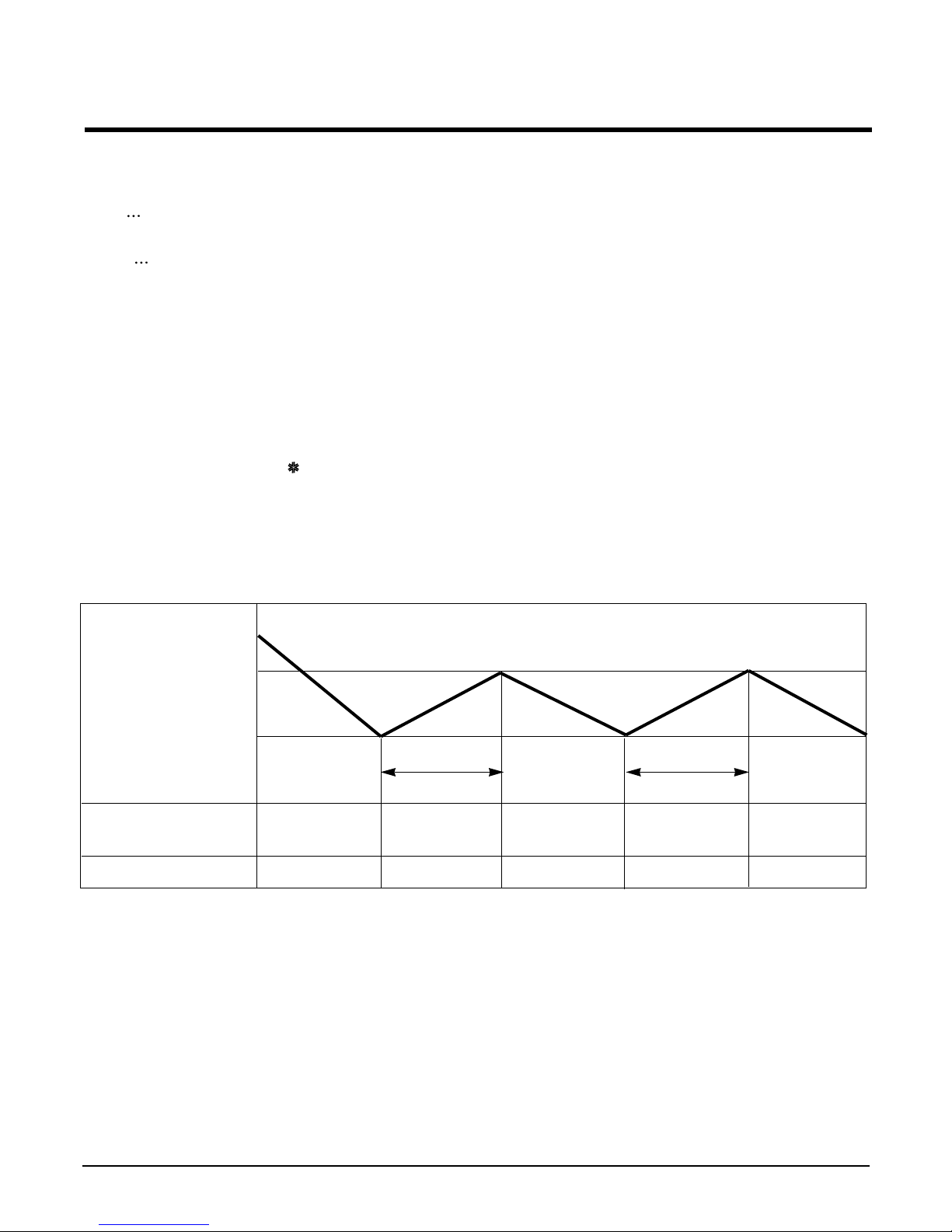
3. Cooling Mode Operation
• When selecting the Cooling( ) Mode Operation, the unit will operate according to the setting by the remote con-
troller and the operation diagram is as following
Intake Air temp.
COMP. ON
(SET TEMP.+0.5°C)
COMP. OFF
(SET TEMP. -0.5°C) More than More than
3 minutes 3 minutes
Selecting Selecting Selecting
fan speed fan speed fan speed
COMPRESSOR ON OFF ON OFF ON
INDOOR FAN Low Low
- 12 -
Copyright ©2008 LG Electronics. Inc. All right reserved.
Only for training and service purposes
LGE Internal Use Only
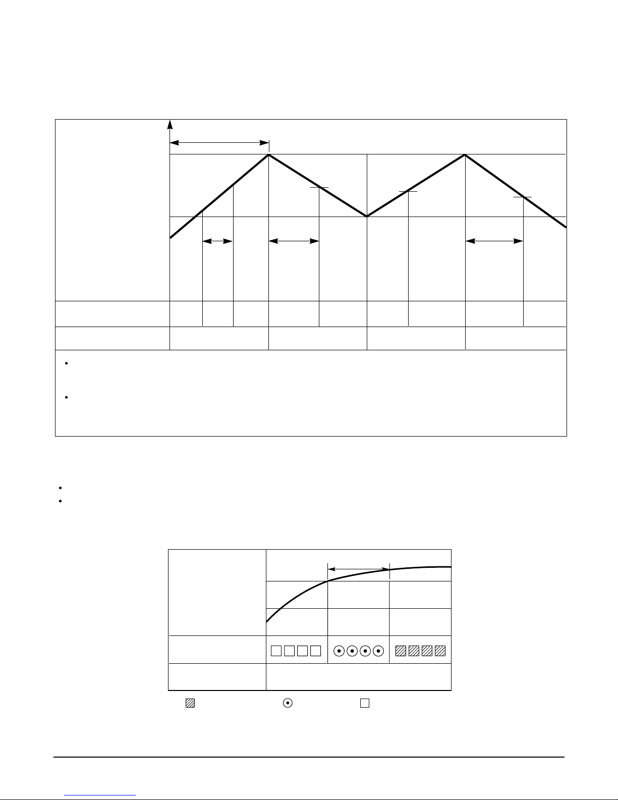
Intake Air temp.
Setting temp.+3°C
(Compressor OFF)
Setting temp.
(Compressor ON)
INDOOR FAN Low OFF Low Low OFF
COMPRESSOR ON OFF ON OFF
A point; While the indoor Heat-Exchanger temperature is higher than 40°C fan operates at low speed, when
it becomes lower than 40˚C fan stops.
B point; When the indoor Heat-Exchanger temperature is higher than 42°C, fan operates at seleted fan
speed, when it becomes lower than 39°C, the fan operates at low speed.
4. Heating Mode Operation (Except Cooling Model)
The unit will operate according to the setting by the remote controller and the operation diagram is shown as following.
Hot Start
Low
Selecting
Fan Speed
minimum 3min
Selecting fan
speed
minimum
10sec.
1min
AA
minimum
10sec.
B
5. Hot-Start Control
The indoor fan stops until the evaporator piping temperature will be reached to 31°C.
The operation diagram is as following.
PIPING
TEMPERATURE
1min
COMPRESSOR
INDOOR FAN
ON
28°C
: Selected Fan : Low Fan : Fan Stop
31°C
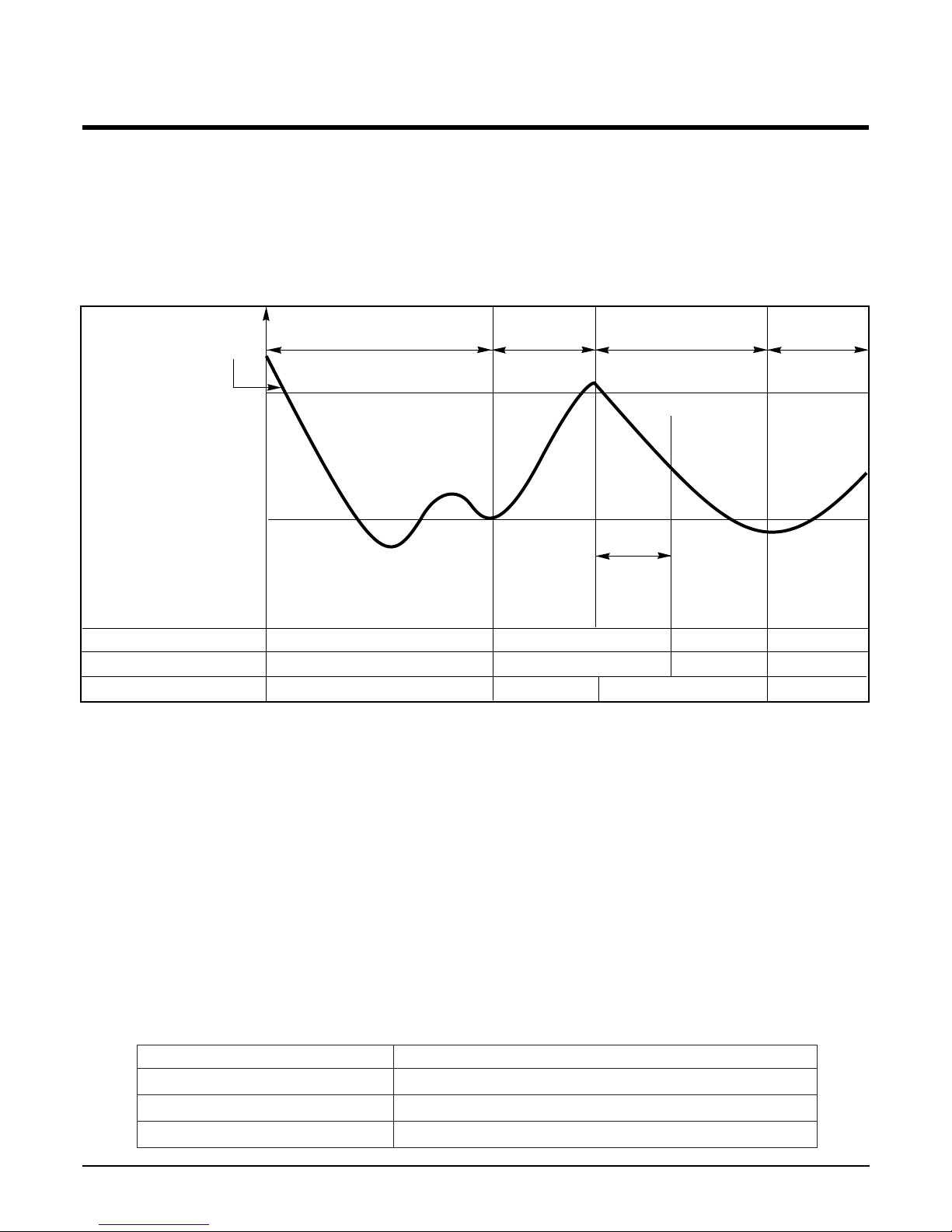
6. Defrost Control
• Defrost operation is controlled by timer and sensing the outdoor piping temperature.
• The defrost starts only when the outdoor pipe temperature falls below -6°C after 45 minutes passed from starting
of heating operation.
• Defrost ends after 10 minutes passed from starting of defrost operation or when the outdoor pipe
temperature rises over 12°C even if before 10 minutes.
7. Auto Restarting Operation
• When the power is restored after a sudden power failure while in appliance operation, the mode before the
power failure is kept on the memory and the appliance should be on the automatically operates in the mode on
the memory.
• Operation Mode that is kept on the memory
- State of Operation ON/OFF
- Operation Mode/Setting Temp/Selected Airflow Speed
• If no input by the remote controller within 7 hr after the appliance operates by the Auto Restarting operation,
the appliance is forced to stop at the moment of 7-hr elapse.
8. Self-Diagnosis Function
• 'CHECK' will flash in the remote controller display when a problem occurs. Then please contact your dealer.
• Correct the accident point as shown in the table below before restarting operation.
• During the normal operation 'CHECK' won't be displayed in the remote controller.
- 13 -
Copyright ©2008 LG Electronics. Inc. All right reserved.
Only for training and service purposes
LGE Internal Use Only
More than 45 minutes of
heating operation
Outdoor Pipe Temp.
Indoor Fan
Compressor
4-Way Valve
ON
ON
ON
ON
OFF
ON
OFF
HOT-
START
ON
ON OFF OFFON
12°C
(Defrost OFF)
-6°C
(Defrost ON)
Within
10 minutes
Defrost
Defrost
More than 45 minutes of
heating operation
Remote controller LCD Accident Point
F1 Indoor temperature thermistor error
F2 Indoor piping thermistor error
F3 Indoor/Outdoor unit communication error
 Loading...