

LG LB-C306GTA2 Installation Manual

LG Ceiling Duct-Type
Air Conditioner
INSTALLATION MANUAL
LG
MODELS: LB-C186HSA2
LB-C246HSA2
LB-C306GTA2
LB-C366GTA2/3
LB-C428GTA2
LB-C488RTA0
LB-C608RTA0
IMPORTANT
• Please read this installation manual completely before
installing the product.
• When the power cord is damaged, replacement work shall
be performed by authorized personnel only.
• Installation work must be performed in accordance with
the national wiring standards by authorized personnel
only.
• Please retain this installation manual for future reference
after reading it thoroughly.

2 Ceiling Duct Type Air Conditioner
Ceiling Duct Type Air Conditioner Installation Manual
TABLE OF CONTENTS
Safety Precautions..............3
Introduction .........................6
Installation of Indoor,
Outdoor Unit ........................7
Connecting Pipes to the
Indoor Unit .........................17
Connecting Pipes to the
Outdoor Unit ......................19
Checking the Drainage .....19
Connecting Cables
between Indoor Unit and
Outdoor Unit ......................20
Air Purging of the
Connecting Pipes and the
Indoor Unit .........................23
Group Control....................24
Two Thermistor system ....24
E.S.P.(External Static
Pressure) Setting ..............25
How to Set E.S.P? .............26
External Static Pressure &
air Flow...............................27
Auto Function Setting.......27
Checking the
Power Cord ........................28
Installation
Requirements
Required Parts Required Tools
•
Four Type “A” screws
•
Connecting cable
•
Level
•
Screw driver
•
Electric drill
•
Hole core drill (ø70mm)
•
Pipes: Gas side .....
5
/8", 3/4"
Liquid side .............
1
/4", 3/8", 1/2"
•
Insulated drain hose
•
Insulation materials
•
Flaring Tools set
•
Additional Drain hose
(Inner Dia...............25mm)
•
Screw driver
•
Hexagonal Wrench (4mm/5mm)
•
Gas-leak Detector
To prevent injury to the user or other people and property damage, the following instructions must be followed.
■ Incorrect operation due to ignoring instruction will cause harm or damage. The seriousness is classified by the
following indications.
■ Meanings of symbols used in this manual are as shown below.
This symbol indicates the possibility of death or serious injury.
This symbol indicates the possibility of injury or damage.
Be sure not to do.
Be sure to follow the instruction.
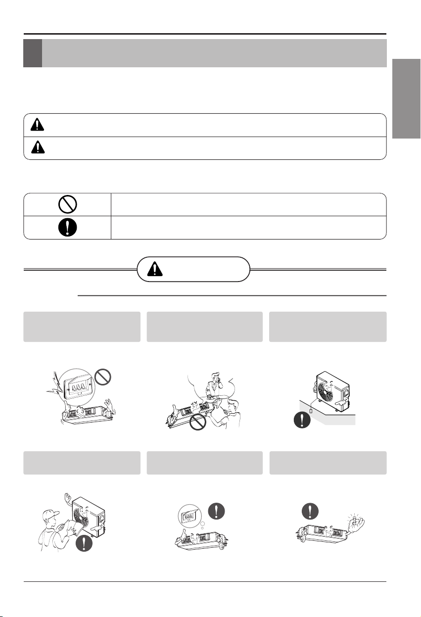
WARNING
■ Installation
Do not use a defective or underrated
circuit breaker. Use this appliance on
a dedicated circuit.
• There is risk of fire or electric shock.
For electrical work, contact the
dealer, seller, a qualified electrician,
or an Authorized Service Center.
• Do not disassemble or repair the product.
There is risk of fire or electric shock.
Always ground the product.
• There is risk of fire or electric shock.
Install the panel and the cover of
control box securely.
• There is risk of fire or electric shock.
Always install a dedicated circuit
and breaker.
• Improper wiring or installation may cause fire
or electric shock
Use the correctly rated breaker or
fuse.
• There is risk of fire or electric shock.
Safety Precautions
Installation Manual 3
ENGLISH
Safety Precautions
WARNING
CAUTION
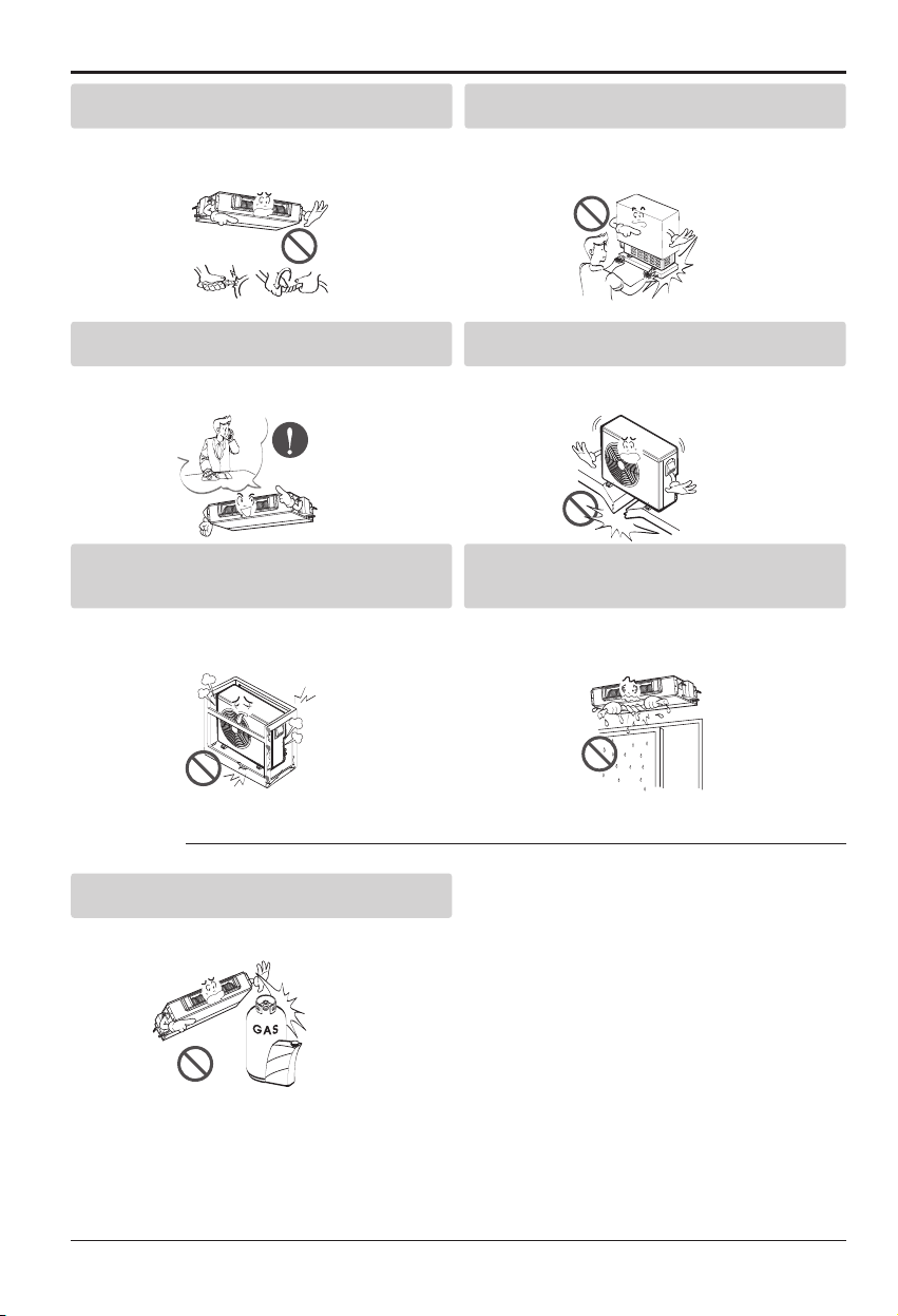
■ Operation
Do not modify or extend the power cable.
• There is risk of fire or electric shock.
Be cautious when unpacking and installing the product.
• Sharp edges could cause injury. Be especially careful of the case
edges and the fins on the condenser and evaporator.
For installation, always contact the dealer or an
Authorized Service Center.
• There is risk of fire, electric shock, explosion, or injury.
Do not install the product on a defective installation
stand.
• It may cause injury, accident, or damage to the product.
Be sure the installation area does not deteriorate with
age.
• If the base collapses, the air conditioner could fall with it, causing
property damage, product failure, and personal injury.
Do not let the air conditioner run for a long time when the
humidity is very high and a door or a window is left open.
• Moisture may condense and wet or damage furniture.
Do not store or use flammable gas or combustibles near
the product.
• There is risk of fire or failure of product.
4 Ceiling Duct Type Air Conditioner
Safety Precautions
Gasolin
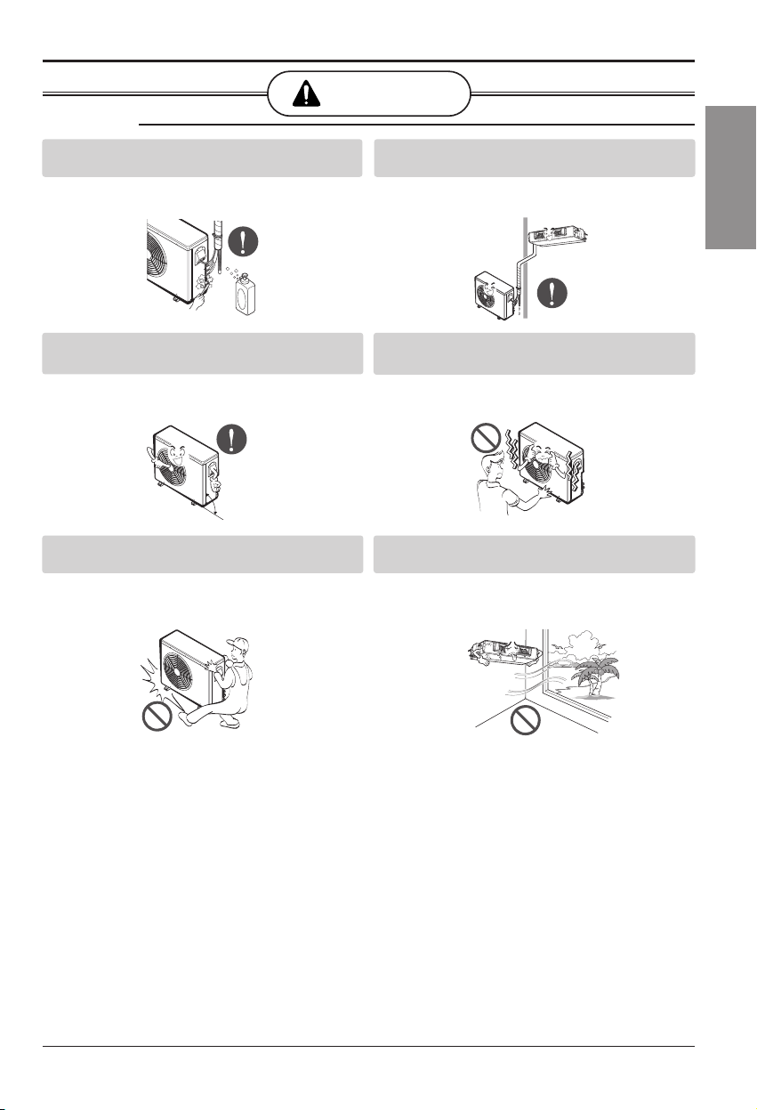
■ Installation
CAUTION
Always check for gas (refrigerant) leakage after
installation or repair of product.
• Low refrigerant levels may cause failure of product.
Install the drain hose to ensure that water is drained
away properly.
• A bad connection may cause water leakage.
Keep level even when installing the product.
• To avoid vibration or water leakage.
Do not install the product where the noise or hot air from
the outdoor unit could damage the neighborhoods.
• It may cause a problem for your neighbors.
Use two or more people to lift and transport the product.
• Avoid personal injury.
Do not install the product where it will be exposed to sea
wind (salt spray) directly.
• It may cause corrosion on the product. Corrosion, par ticularly on the
condenser and evaporator fins, could cause product malfunction or
inefficient operation.
Safety Precautions
Installation Manual 5
ENGLISH
90°
6 Ceiling Duct Type Air Conditioner
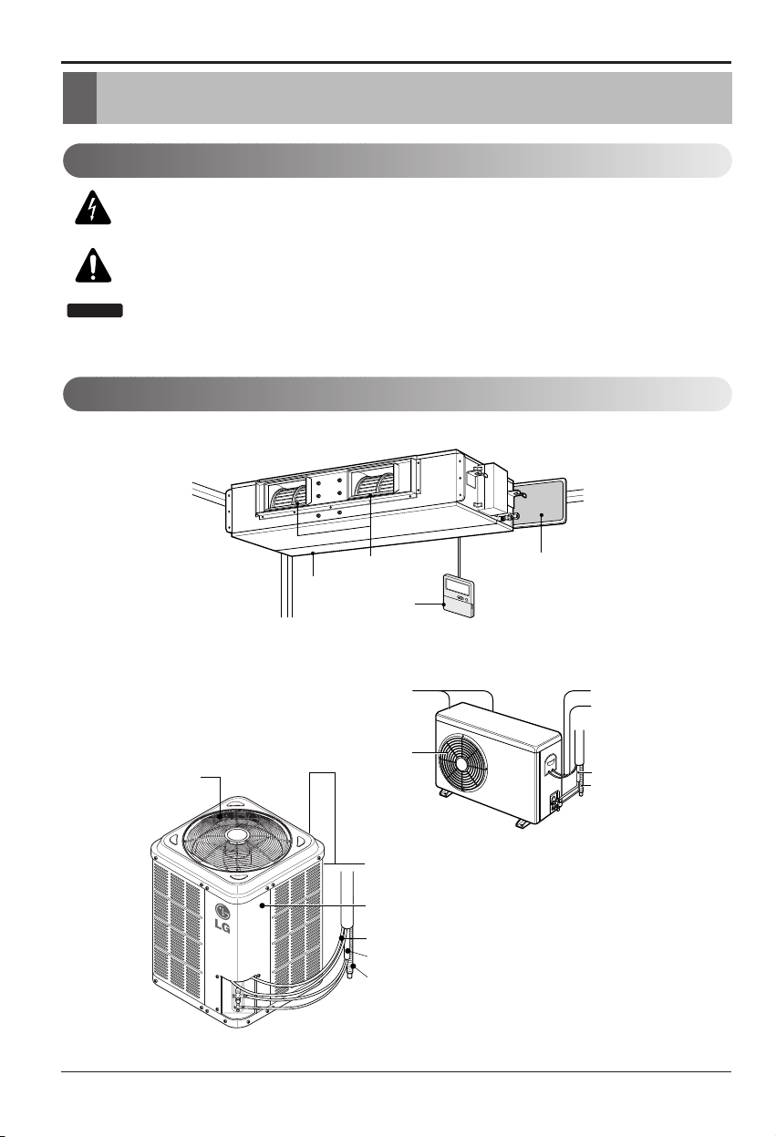
Installation Parts Provided
Air filters
Air outlet vents
Air intake vents
Remote Controller
(Rear)
(Side)
Air intake
vents
Air outlet vents
Piping
Drain hose
Connecting wire
Control cover
Air Intake
(side, rear)
Connecting Wire
Drain Hose
Power Wire
Connection Tube
Air Outlet
Vents
This symbol alerts you to the risk of electric shock.
This symbol alerts you to hazards that could cause harm to the
air conditioner.
This symbol indicates special notes.
NOTICE
Introduction
Symbols Used in this Manual
Features
Installation Manual 7
ENGLISH
Installation of Indoor, Outdoor Unit
Installation of Indoor, Outdoor Unit
Indoor unit
Install the air conditioner in the location that
satisfies the following conditions.
• The place shall easily bear a load exceeding
four times the indoor unit’s weight.
• The place shall be able to inspect the unit as
the figure.
• The place where the unit shall be leveled.
• The place shall allow easy water
drainage.(Suitable dimension “H” is necessary
to get a slope to drain as figure.)
• The place shall easily connect with the
outdoor unit.
• The place where the unit is not affected by an
electrical noise.
• The place where air circulation in the room will
be good .
• There should not be any heat source or steam
near the unit
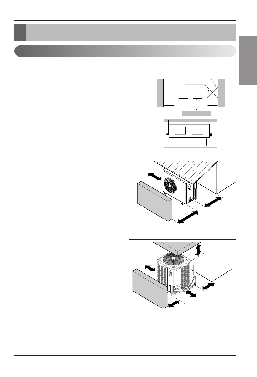
Outdoor unit
• If an awning is built over the unit to prevent
direct sunlight or rain exposure, be careful that
heat radiation from the condenser is not
restricted.
• There should not be any animals or plants
which could be affected by hot air discharged.
• Ensure the spaces indicated by arrows from
the wall, ceiling, fence or other obstacles.
Selection of the best location
H
600600
Top view
(unit: mm)
Front view
Front
Inspection hole
(600X600)
Control box
1000
More than
30cm
Fence or
obstacles
Sunroof
More than
30cm
More than
70cm
More than
90cm
Fence or
obstacles
Fence or
Fence or
obstacles
obstacles
More than 90cm
✽
More than 90cm
More than 120cm
More than
90cm
8 Ceiling Duct Type Air Conditioner
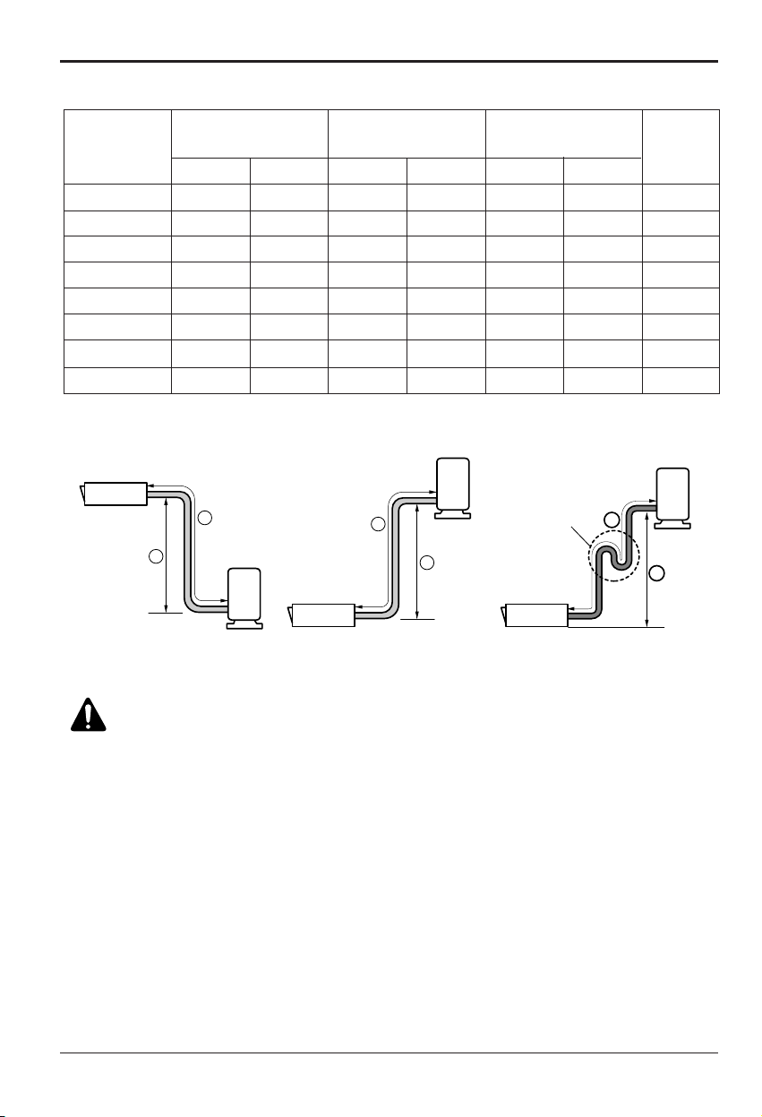
Installation of Indoor, Outdoor Unit
Piping length and the elevation
Outdoor unit
Indoor unit
A
B
Outdoor unit
Indoor unit
A
B
A
Oil trap
Outdoor unit
Indoor unit
B
If piping length is more than 5m
30
35
30
40
50
50
60
90
Capacity
Gas
5/8"
5/8"
5/8"
5/8"
5/8"
3/4"
3/4"
3/4"
Liquid
1/4"
1/4"
1/4"
1/4"
1/4"
3/8"
3/8"
1/2"
Elevation B(m)
Length A(m)
*Additional
refrigerant
(g/m)
Pipe Size
(Diameter: Ø)
Standard
7.5
7.5
7.5
7.5
7.5
7.5
7.5
7.5
Standard
5
5
5
5
5
5
5
5
Max.
30
30
30
30
30
30
30
30
Max.
15
15
15
15
15
15
15
15
18K BTU/h
24K BTU/h
30K BTU/h
36K BTU/h
LB-C366GTA3
42K BTU/h
48K BTU/h
60K BTU/h
CAUTION:
• If 48k Model is installed at a distance of 15m, 450g of refrigerant
should be added (15-7.5) x 60g = 450g
• Capacity is based on standard length and maximun allowance length
is on the basis of reliability.
• Improper refrigerant charge may result in abnormal cycle.
• Oil trap should be installed every 10 meters.
Installation Manual 9
ENGLISH
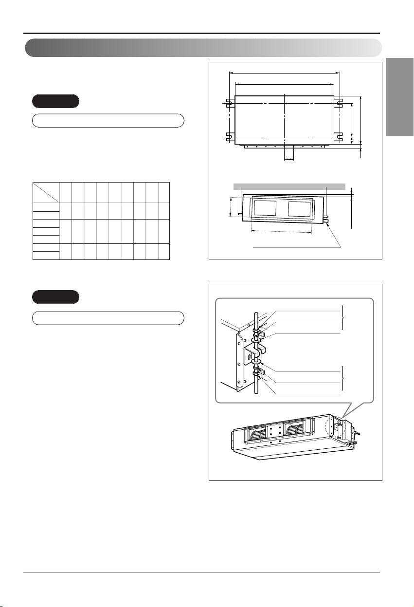
Installation of Indoor, Outdoor Unit
Indoor unit installation
Installation of Unit
Install the unit above the ceiling correctly.
• Apply a joint-canvas between the unit and duct
to absorb unnecessary vibration.
• Apply a filter Accessory at air return hole.
• Install the unit leaning to a drainage hole side
as a figure for easy water drainage.
• A place where the unit will be leveled and that
can support the weight of the unit.
• A place where the unit can withstand its
vibration.
• A place where service can be easily
performed.
CASE 1
POSITION OF SUSPENSION BOLT
Drainage hole
A
B
C
1-3 mm
D
(G)
H
I
EF
CASE 2
POSITION OF CONSOLE BOLT
(Unit:mm)
18K BTU/h
948 880 355 45.5 450 30 87 750 163
24K BTU/h
30K BTU/h
36K BTU/h 1248 1180 355 45.5 450 30 87 830 186
42K BTU/h
48K BTU/h
1292 1230 477 56 590 30 120 1006 294
60K BTU/h
Dimension
Capacity
ABCDE F(G)HI
M10 Nut
M10 SP. washer
M10 washer
M10 washer
M10 SP. washer
M10 Nut
X 4
X 4
X 4
X 4
X 4
X 4
(Local
supply)
(Local
supply)
10 Ceiling Duct Type Air Conditioner
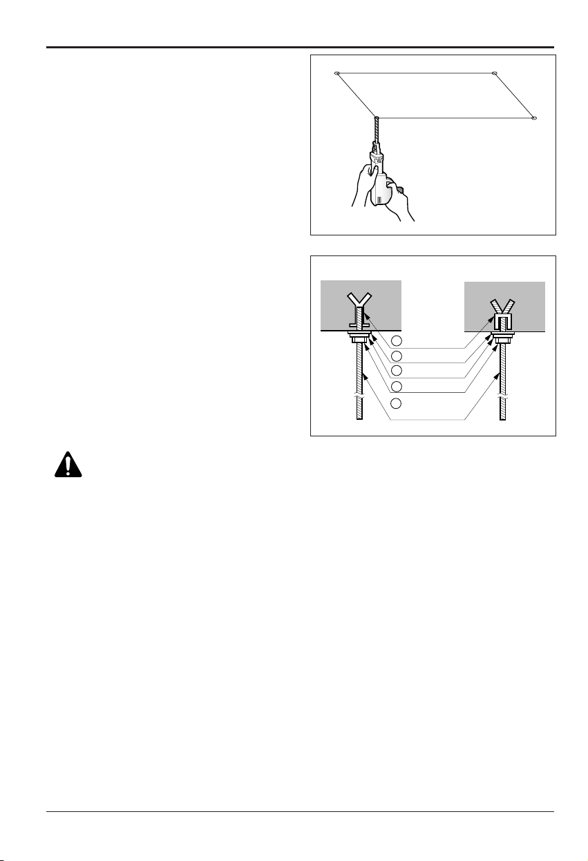
Installation of Indoor, Outdoor Unit
• Select and mark the position for fixing bolts.
• Drill the hole for set anchor on the face of
ceiling.
• Insert the set anchor and washer onto the
suspension bolts for locking the suspension
bolts on the ceiling.
• Mount the suspension bolts to the set anchor
firmly.
• Secure the installation plates onto the
suspension bolts (adjust level roughly) using
nuts, washers and spring washers.
CAUTION:
Tighten the nut and bolt to
prevent unit falling.
Old building New building
1 Set anchor
2 Plate washer
3 Spring washer
4 Nut
5 Suspension
bolts
 Loading...