

LG LB-B2156QC, LB-B2206QC, LB-B2258QC, LMA36B2ALI, LMA48B2ALI Installation Manual
...
IMPORTANT
Please read through this manual. It contains valuable
information about your air conditioner. This manual may
help save time and money by explaining proper product
maintenance and preventing improper use.
PRECAUTIONS
Pay close attention to precautions in order to prevent
potential hazards and damage from misuse or improper
installation. LG is not responsible for any damages caused
by misuse of the product.
LG
Low Static Hide Away Type Air Conditioner
OWNER'S & INSTALLATION
MANUAL
LG
P/No.: MFL62760202

1.The following should be always observed for safety..............................
2. Installation of Indoor, Outdoor unit .........................................................
3. Connecting Pipes to the Indoor Unit .....................................................
4. Connecting Pipes to the Outdoor Unit ..................................................
5. IR Remote Sensor installation & operation detail.................................
6. Connecting Cables between Indoor Unit and Outdoor Unit ................
7. Air Purging of the Connecting Pipes and the Indoor Unit.................... 27
OUT-LINE OF INSTALLATION
Installation works Installation Parts Required tools
A)
B)
C)
D)
E)
F)
•
Four Type “A”
screws
•
Connecting cable
•
Level
•
Screw driver
•
Electric drill
•
Hole core drill (ø70mm)
1) Preparation of Piping...12
•
Pipes: Gas side
Liquid side
•
Insulated drain hose
•
Insulation materials
•
FlaringTools set
1) Connecting the pipes to
the Outdoor Unit ..........14
A) Circuit Breaker Detail......................16
•
Screw driver
•
Hexagonal Wrench (4mm/5mm)
•
Gas-leak Detector
2
4
3
12
14
14
16
Index Page No.
Selection of best location of indoor .....04
Ceiling dimension & Hanging blot detail........05
Filter convertible option.......06
Drain piping .........................07
Insulation of the piping & drain...08
Out door unit best location & piping ....10
B) Wiring diagram, wiring specification & interconnection
detail.................................. ................17
C) Outdoor Wire Routine & Pipe Routine.......25
8. Operating Instructions.................... ........................................................ 28
A) Indoor Unit, Outdoor Unit ...................... 28
B) Remote Control Preparation .. .............. 29
C) Remote Control Operations .. ............... 30
3
1. The following should be always observed for safety
• Please report to or take consent by the supply authority before connecting to the system.
• Be sure to read "THE FOLLOWING SHOULD BE ALWAYS OBSERVED FOR SAFETY" before
installing the air conditioner.
• Be sure to observe the cautions specified here as they include important items related to safety.
• The indications and meanings are as follows.
• After reading this manual, be sure to keep it together with the owner's manual in an accessible
place.
Could lead to death, serious injury, etc.
Do not install it yourself (customer).
Perform the installation securely referring to the
installation manual.
Install the unit securely in a place which can bear the
weight of the unit.
Perform electrical work according to the installation
manual and be sure to use an exclusive circuit.
Attach the electrical part cover to the indoor unit and
the service panel to the outdoor unit securely.
Be sure to use the part provided or specified parts for
the installation work.
Check that the refrigerant gas do not leak after
installation is completed.
Perform the drainage/piping work securely
according to the installation manual.
Use the specified wires to connect the indoor and the
outdoor units securely and attach the wires firmly to
the terminal board connecting sections so the stress
of the wires is not applied to the sections.
• Incomplete installation could cause injury due to fire, electric shock,
the unit falling or a leakage of water. Consult the dealer from whom
you purchased the unit or special installer.
• Incomplete installation could cause a personal injury due to
fire, electric shock, the unit falling or a leakage of water.
• When installed in an insufficient strong place, the unit could fall
causing injured.
• Incomplete connecting and fixing could cause fire.
• If the capacity of the power circuit is insufficient or there is
incomplete electrical work, it could result in a fire or an electric
shock.
• The use of defective parts could cause an injury or leakage of
water due to a fire, electric shock, the unit falling, etc.
• If there is a defect in the drainage/piping work, water
could drop from the unit and household goods could be
wet and damaged.
Do not install the unit in a place where an
inflammable gas leaks.
• If gas leaks and accumulates in the area surrounding the unit, it
could cause an explosion.
• If the electrical part cover if the indoor unit and/or the service
panel if the outdoor unit are not attached securely, it could result
in a fire or electric shock due to dust, water, etc.
Could lead to serious injury in particular environments when operated incorrectly.
WARNING
WARNING
CAUTION
CAUTION
4
2). Installation of indoor & Outdoor.
Indoor unit
Install the air conditioner in the location that satisfies the following conditions.
• The place shall easily bear a load exceeding four times the
indoor unit’s weight.
• The place shall be able to inspect the unit as the figure.
• The place where the unit shall be leveled.
• The place shall easily connect with the outdoor unit.
• The place where the unit is not affected by an electrical
noise.
• The place where air circulation in the room will be good .
• There should not be any heat source or steam near the
unit
Confirm the positional relationship between the unit and
suspension bolts.
• Installation the ceiling opening to clean the filter or service
under the product.
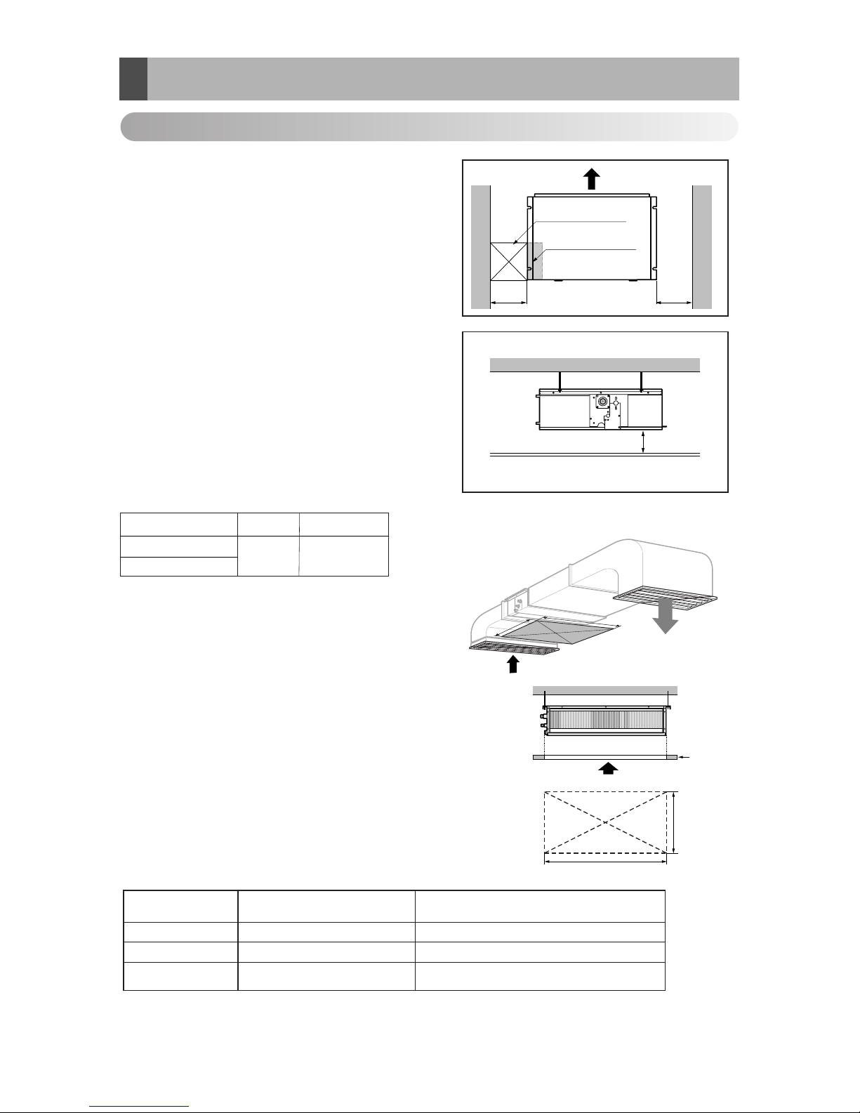
A).Selection of the best location of Indoor
Inspection hole
(600 x 600)
Control box
H=20 or more
• Suitable dimension "H" is necessary to get a slooe
to drain as aiven in the fiaure
Side view
(unit: mm)
600600
A(Min)
B(Min)
Ceiling
Service Space
A
B
Capacity(Btu/h)
A
B
18/24/30k
600 1100
(Length: mm)
Low static Duct type
Minimum height for motor replacement.
Less than 20cm
Hole size should be
more than the size of IDU.
Insufficient space. Difficult for servicing
20cm to 100cm2
Sufficient space in the ceiling for servicing.
More than 100cm1
Remarks
Distance between
False ceiling & Actual ceiling
Number of
Inspection hole
[Inspection Hole Standard]
36/48/60k
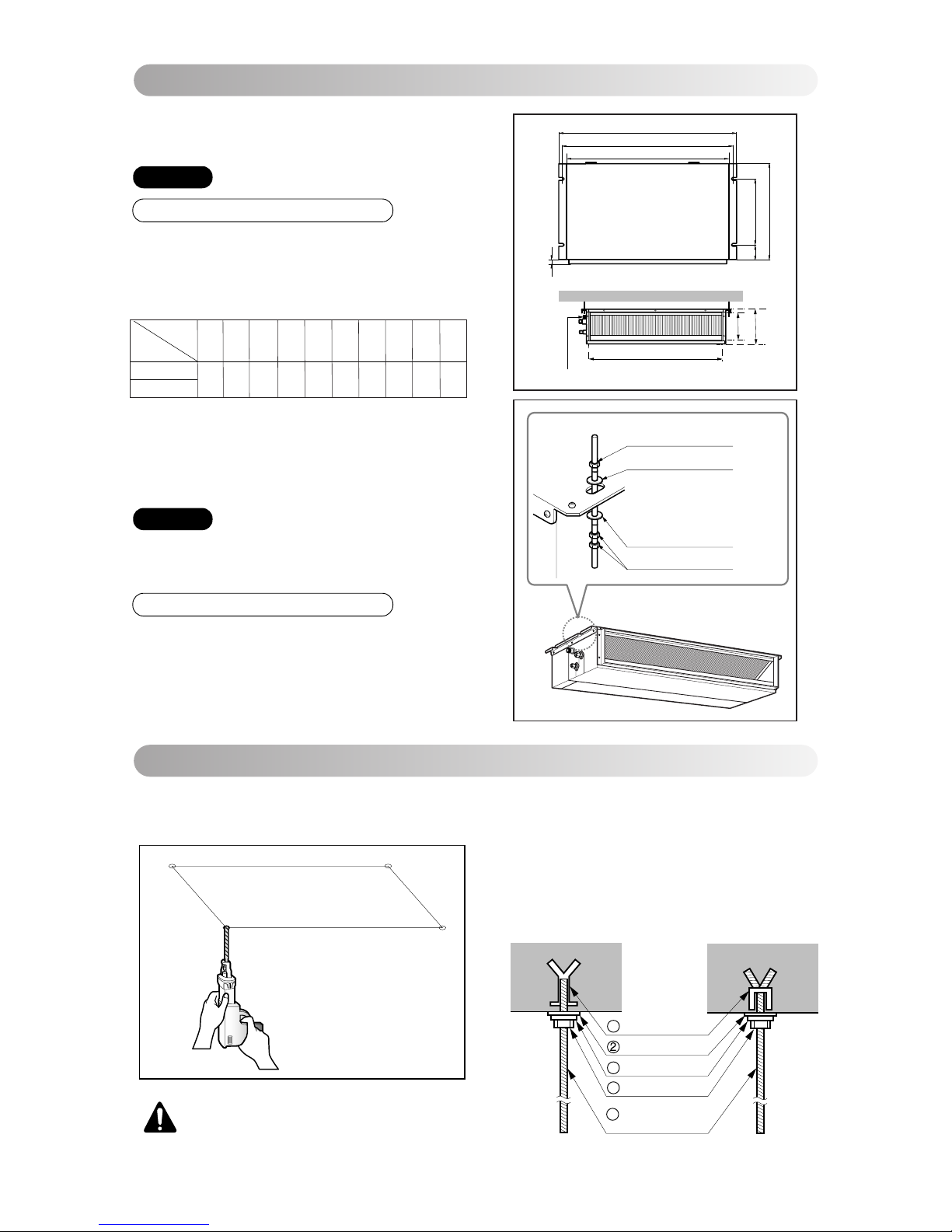
B).Ceiling dimension and hanging bolt location
Installation of Unit
Install the unit above the ceiling correctly.
• Apply a joint-canvas between the unit and duct to absorb
unnecessary vibration.
• Apply a filter Accessory at air return hole.
• Install the unit leaning to a drainage hole side as a figure
for easy water drainage.
• A place where the unit will be leveled and that can support
the weight of the unit.
• A place where the unit can withstand its vibration.
• A place where service can be easily performed.
CASE 1
POSITION OF SUSPENSION BOLT
(Unit:mm)
18/24/30k BTU/h
1130 1180 383 575 93 190 21 1065 163 1100
Dimension
Capacity(Btu/h)
A B C D E F G H I J
CE
G
D
A
J
B
I
F
H
Drainage hole
Drain Pump use
M10 Nut
M10 washer
X 4
X 4
M10 Nut
M10 washer
X 4
X 8
CASE 2
POSITION OF CONSOLE BOLT
5
• Select and mark the position for fixing bolts.
• Drill the hole for set anchor on the face of ceiling.
• Insert the set anchor and washer onto the suspension bolts for locking the suspension bolts on the
ceiling.
•
Mount the suspension bolts to the set anchor firmly.
• Secure the installation plates onto the suspension
bolts (adjust level roughly) using nuts, washers
and spring washers.
1 Set anchor
Old building New building
Plate washer
3 Spring washer
4 Nut
5 Suspension
bolts
Indoor Unit Installation
CAUTION : Tighten the nut and bolt
to prevent unit falling.
36/48/60k BTU/h
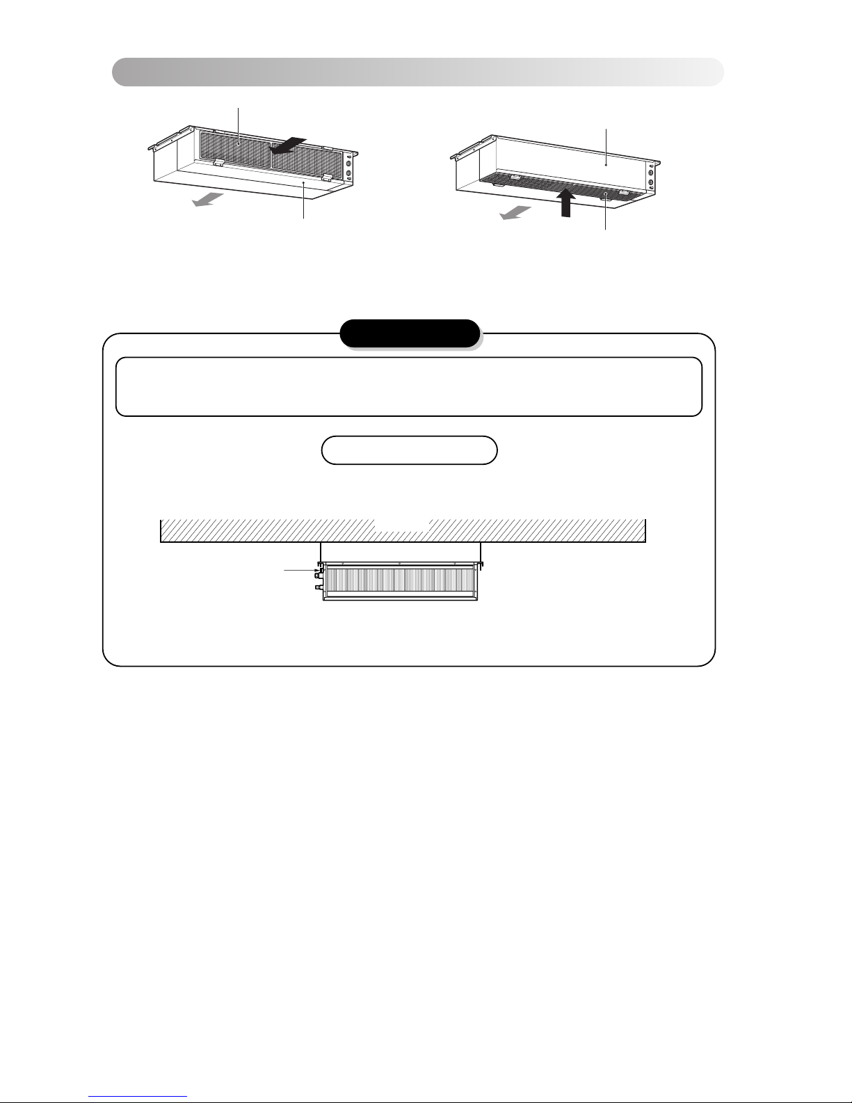
• Low static duct type in case of suction from back
side.
• Low static duct type in case of suction from bottom
side.
Air Filter
Air outlet
Panel Rear
Air outlet
Air Filter
Panel Rear
C).Filter convertible option.
6
CAUTION
Ceiling
Drain Pump use
Drainage hole
Front of view
1. Install declination of the indoor unit is very important for the drain of the duct type air conditioner.
2. Minimum thickness of the insulation for the connecting pipe shall be 19mm.
• The unit must be horizontal or declined to the drain hose connected when finished
installation.
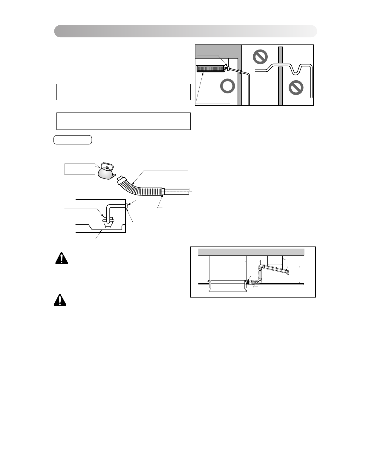
The air conditioner uses a drain pump to drain water.
Use the following procedure to test the drain pump operation:
• Connect the main drain pipe to the exterior
an d leav e it pr ovisi o nally until the te st
comes to an end.
• Feed water to the flexible drain hose and
check the piping for leakage.
• Be sure to check the drain pump for normal
operating and noise when electrical wiring
is complete.
• When the test is comple te, connect the
flexible drain hose to the drain port on the
indoor unit.
Drain test
Feed water
Drain Pump
Drain pan
Flexible drain hose
Main
drain pipe
Glue the joint
Drain
port
Drain hose connection
Use the clip
• Drain piping must have down-slope (1/50 to 1/100): be sure not to
provide up-and-down slope to prevent reversal flow.
• During drain piping connection, be careful not to exert extra force
on the drain port on the indoor unit.
• The outside diameter of the drain connection on the indoor unit is
32mm.
•
Be sure to install heat insulation on the drain piping.
Piping material: Polyvinyl chloride pipe VP-25 and
pipe fittings
Heat insulation material: Polyethylene foam with thickness more than 8 mm.
Upward
routing
not allowed
Pipe clamp
Maintenance
drain port
Indoor unit
D). Drain Piping
7
CAUTION:
After the confirmation of the above conditions, prepare the wiring as follows:
1) Never fail to have an individual power specialized for the air conditioner. As for the method of
wiring, be guided by the circuit diagram posted on the inside of control box cover.
2) Provide a circuit breaker switch between power source and the unit.
3) The screws which fasten the wiring in the casing of electrical fittings are liable to come loose
from vibrations to which the unit is subjected during the course of transportation. Check them
and make sure that they are all tightly fastened. (If they are loose, it could give rise to burn-out
of the wires.)
4) Specification of power source
5) Confirm that electrical capacity is sufficient.
6) Be sure that the starting voltage is maintained at more than 90 percent of the rated voltage
1/50~1/100 slope
Hanger
distance
Hanger Bracket
Max 700mm
Flexible drain hose
Insulation
Metal
clamp
Max 300mm
1~15m
CAUTION : The supplied flexible drain
hose should not be curved, neither
screwed. The curved or screwed hose
may cause a leakage of water.
marked on the name plate.
7) Confirm that the cable thickness is as specified in the power sources specification.
(Particularly note the relation between cable length and thickness.)
8) Never fail to equip a leakage breaker where it is wet or moist.
9) The following troubles would be caused by voltage drop-down.
• Vibration of a magnetic switch, damage on the contact point, fuse breaking, disturbance by the normal function of an overload protection device.
• Proper starting power is not given to the compressor.
HAND OVER
Teach the customer the operation and maintenance procedures, using the operation manual.
(air filter cleaning, temperature control, etc.)
4 EA
Name
Quantity
Shape
for gas pipe
for liquid pipe
Clamp metal
2 EA
Insulation for
fitting
1 SET
Drain hose
1 EA
Clamp
(Tie Wrap)
8 EA
Washer for
hanging backet
(Other)
Standard Accessories
• Owner's manual
• Installation manual
8
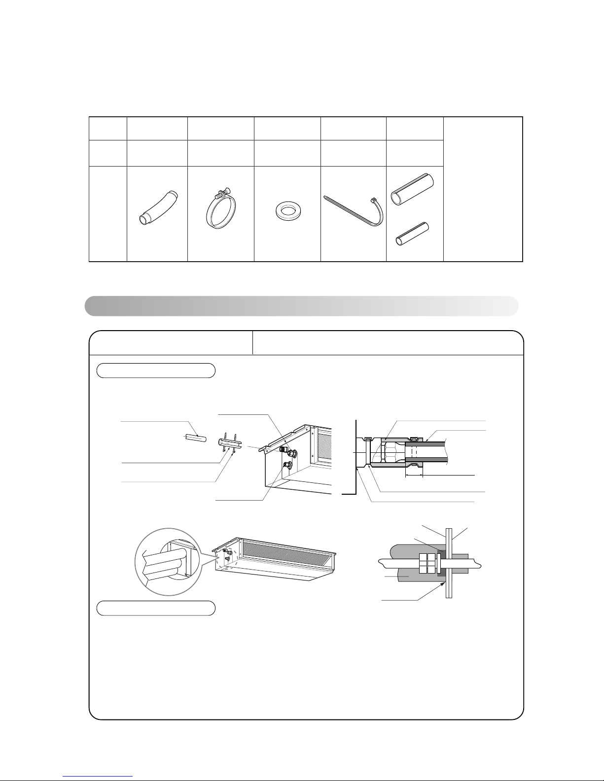
INSULATION, OTHERS
Insulate the joint and tubes completely.
All thermal insulation must comply with local requirement.
INDOOR UNIT
After all workings are finished, check the working and operation.
• Air distribution ............... Is the air circulation good?
• Drain ............................. Is the drainage smoothly and no sweating?
• Gas leakage ................. Is the piping connection correctly?
• Wiring ........................... Is the wiring connection correctly?
• Lock-bolt ....................... Is the lock-bolt of compressor loosened?
• Insulation Is the unit fully insulated?
• Ground Is the unit safely grounded?
THERMAL INSULATION
TEST AND CHECK
Make sure that there is no clearance here.
Overlap with thermal
insulator for piping.
Thermal insulator for refrigerant pipe
(Local supply)
Thermal insulator for
piping(Local supply)
Hose clip for thermal insulator(Local supply)
Union for gas pipe
Refrigerant pipe and thermal
insulator(Local supply)
Union for liquid pipe
Thermal insulator for refrigerant pipe
(Local supply)
Hose clip for thermal insulator
(Local supply)
Felt
Rubber
Insulation
No clearance
Cabinet
E). Insulation of the Piping & Drain

9
B
e
n
z
e
n
e
S
C
O
U
R
I
N
G
C
L
B
A
R
G
E
R
S
I
N
N
E
R
Care and maintenance
Indoor Unit
Caution: Before performing any maintenance, turn off the main power to the system.
Grille, Case, and Remote Control
Turn the system off before cleaning. To clean,
wipe with a soft, dry cloth. Do not use bleach or
abrasives.
Note:
Supply power must be disconnected before
cleaning the indoor unit.
Never use any of the followings:
• Water hotter than 40°C
Could cause deformation and/or
discoloration.
• Volatile substances
Could damage the surfaces
of the air conditioner.
Clean the filter with a vacuum or warm, soapy
water.
• If very dirty, wash with a solution of
detergent in lukewarm water.
• If hot water (50°C or more) is used, filter
may be deformed.
After washing with water, dry well in the shade.
Re-install the air filter.
Air Filter
The air filters behind Indoor unit
(the suction side) should be checked and cleaned
once every 2 weeks or more often if necessary.
1
2
3
Indoor Unit Dimensions (mm)
CE
G
D
A
J
B
I
F
H
Drainage hole
Drain Pump use
(Unit:mm)
18/24/30k BTU/h
1130 1180 383 575 93 190 21 1065 163 1100
Dimension
Capacity(Btu/h)
A B C D E F G H I J
36/48/60k BTU/h
10
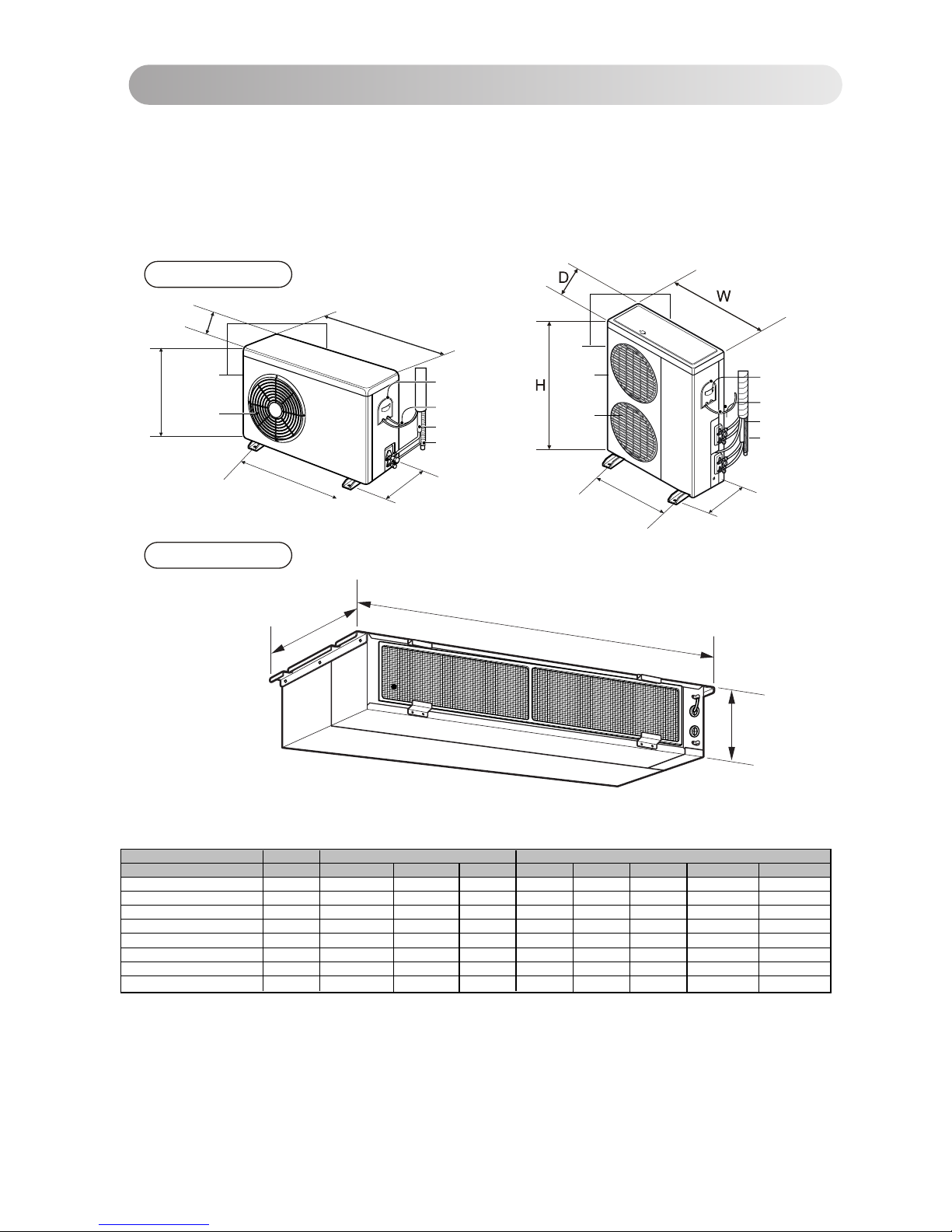
F). Outdoor Unit best location & piping.
The heat exchanger coils and panel vents of the
outdoor unit should be checked regularly. If clogged
with dirt or soot, the heat exchanger and panel vents
may be professionally steam cleaned.
Note:
Dirty or clogged coils will reduce the operating
efficiency of the system and cause higher
operating costs.
Outdoor Unit
Indoor Unit
Outdoor Unit
(Side)
(Rear)
Air outlet
vents
Air intake
vents
Connecting Wire
Connection Pipe
Drain Hose
Control Cover
H
D
W
W
H
D
L2
L1
(Rear)
(Side)
Air outlet
vents
Air intake
vents
L1
L2
Connecting Wire
Connection Pipe
Drain Hose
Control Cover
Model Capacity Indoor dimension Outdoor Dimnesion
W D H W D H L1 L2
LB-B2156QC
1.5 TR
1180 575 190 800 260 555 590 305
LB-B2206QC
2 TR
1180 575 190 800 260 555 590 305
LB-B2256QC / LB-B2258QC
2.5 TR
1180 575 190 870 320 655 545 350
JB-B2156QC
1.5 TR
1180 575 190 870 320 655 545 350
JB-B2258QC
2.5 TR
1180 575 190 870 320 800 545 350
LMA36B2ALI
1.5x2 TR
1180 575 190 870 320 655 545 350
LMA48B2ALI
2.0x2 TR
1180 575 190 906 406 1135 606 465
LMA60B2ALI
2.5x2 TR
1180 575 190 906 406 1135 606 465
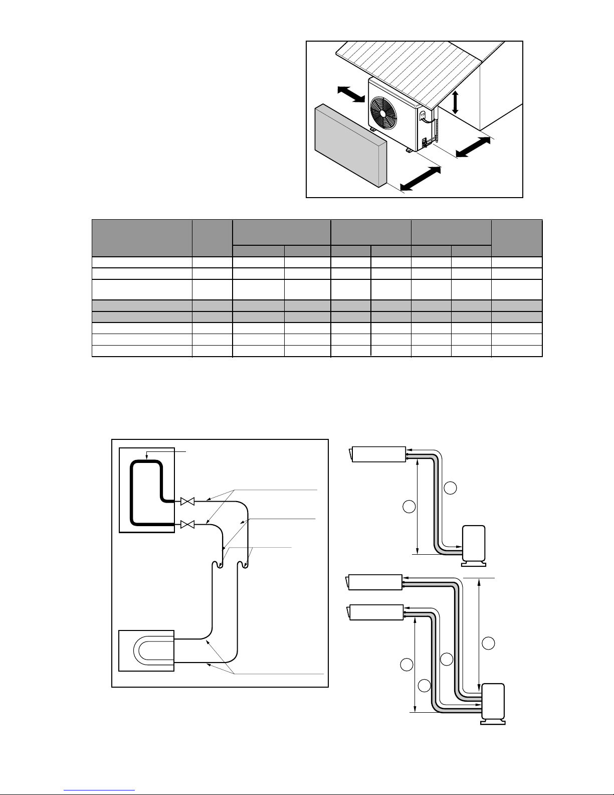
>>Outdoor unit space requirement.
•If an awning is built over the unit to prevent
direct sunlight or rain exposure, be careful
that heat radiation f rom t he condenser is not
restricted.
• There should not be any animals or plants
which could be aff ected by hot air
discharged.
• Ensure the spaces indicated by arrows f rom
the w all, ceiling, f ence or other obstacles.
>>Piping length and the elevation
More than
50cm
More than
50cm
More than
100cm
Sunroof
Fence or
obstacles
• Capacity is based on standard length and maximu m allowance
length is on the basis of reliability .
• Oil trap should be installed every 5 meters.
• If 18K model is installed at a distance of 15m, 150g of refrigerant
should be added [(15-5) x 15g = 150g].
10cm
Gas Liquid standard Max standard Max
1.5 TR 1/2" 1/4" 7.5 30 5 15 R-22 15gm
2 TR 5/8" 1/4" 7.5 30 5 15 R-22 20gm
2.5 TR 5/8" 3/8" 7.5 30 5 15 R-22 25gm
LB-B2156QC
LB-B2206QC
Length(A meter)
Model
Additional
Gas Charge
Pipi Sizes
( Dia In Inch)
Capacity
Elevation(B meter)
1.5 TR 5/8" 3/8" 7.5 80 5 35 R-410 30gmJB-B2156QC
JB-B2258QC 2.5 TR 5/8" 3/8" 7.5 80 5 35 R-410 30gm
11
LB-B2256QC/
LB-B2258QC
LMA36B2ALI 1.5x2 TR 1/2" x 2 1/4"x2 5 30 15 R-22 15gm
LMA48B2ALI 2.0x2 TR 5/8" x 2 1/4"x2 5 30 15 R-22 20gm
LMA60B2ALI 2.5x2 TR 5/8" x 2 3/8"x2 5 30 15 R-22 25gm
5
5
5
Indoor unit
Outdoor unit
B
A
U-Trap
Use seamless pipe
Flared connection (union)
Flared connections
Outdoor
Factory charged gas
Indoor
(Service valves)
Indoor unit
Outdoor unit
B
A
B
A
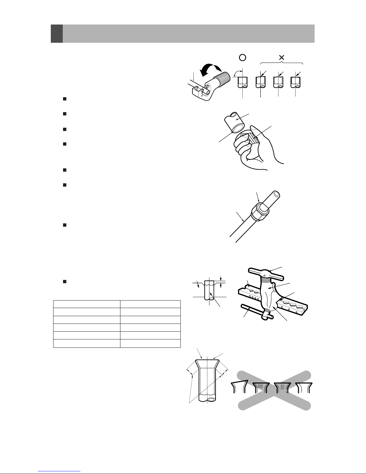
3-1. Preparation of Piping
3. Connecting Pipes to the Indoor Unit
Main cause of gas leakage is defect in
flaring work. Carry out correct flaring work
in the following procedure.
1) Cut the pipes and the cable.
Use the accessory piping kit or the pipes
purchased locally.
Measure the distance between the
indoor and the outdoor unit.
Cut the pipes a little longer than
measured distance.
Cut the cable 1.5m longer than the pipe
length.
2) Burrs removal
Completely remove all burrs from the cut
cross section of pipe/tube.
Put the end of the copper tube/pipe to
downward direction as you remove burrs
in order to avoid to let burrs drop in the
tubing.
3) Putting nut on
Remove flare nuts attached to indoor
and outdoor units, than put them on
pipe/tube having completed burr
removal.
(Not possible to put them on after flaring
work)
4) Flaring work
Carry out flaring work using flaring tool
as shown below.
Firmly hold copper tube in a bar(or die) as
indicated dimension in the table above.
5) Check
Compare the flared work with figure.
If flare is noted to be defective, cut off
the flared section and do flaring work
again.
Copper
tube
90
Slanted Uneven Rough
Pipe
Reamer
Point down
Flare nut
Copper tube
Bar
Copper pipe
Clamp handle
Red arrow mark
Cone
Yoke
Handle
Bar
"A"
Inclined
Inside is shining without scratches.
Smooth all round
Even length
all round
Surface
damaged
Cracked Uneven
thickness
= Improper flaring =
Outside Diameter "A"
1/4" 0~0.5
3/8" 0.5~0.8
1/2" 0.5~0.8
5/8" 0.8~1.0
3/4" 1.0~1.3
12
 Loading...