

LG StudioWorks 560LS, LB570F-EA Service Manual

+
COLOR MONIT OR
SER VICE MANUAL
Website:http://biz.LGservice.com
E-mail:http://www.LGEservice.com/techsup.html
CAUTION
BEFORE SERVICING THE UNIT,
READ THE SAFETY PRECAUTIONS IN THIS MANUAL.
CHASSIS NO. : CL-18
F ACTORY MODEL: LB570F
MODEL: StudioWorks 560LS (LB570F-EA)
*( ) ID LABEL MODEL No.
CONTENTS
SPECIFICATIONS
- 2 -
1. LCD CHARACTERISTICS
Type : Color Active Matrix TFT LCD
Size : 15.1inch (38.35cm)
Pixel Pitch : 0.3mm x 0.3mm
Pixel Format : 1024 x 768 pixels (XGA)
RGB Stripe Arrangement
Color Depth : 6-bit, 262,000 colors
Active Video Area : 307mm x 230mm
Surface Treatment : Anti-Glare, Hard Coating (3H)
Backlight Unit : CCFL (Cold Cathode
Fluorescent Lamp)
2. OPTICAL CHARACTERISTICS
2-1. Viewing Angle by Contrast Ratio
≥
10
Left : 60° typ., 55° min.
Right : 60° typ., 55° min.
Top : 45° typ., 40°min.
Bottom : 45° typ., 40° min.
2-2. Luminance : 200 cd/m
2
typ.
2-3. Angle at Half Luminance
Left : 75° min.
Right : 75° min.
Top : 55° min.
Bottom : 55° min.
2-4. Contrast Ratio : 200° typ.
3. SIGNAL (Refer to the Timing Chart)
3-1. Sync Signal
1) Type : Separate Sync. (Horizontal & Vertical)
2) Input Voltage Level: Low=0~0.8V, High=2.1~5.5V
3) Sync Polarity : Positive or Negative
3-2. Video Input Signal
1) Type : R, G, B Analog
2) Voltage Level : 0~0.714 V
a) Color 0, 0 : 0 Vp-p
b) Color 7, 0 : 0.467 Vp-p
c) Color 15, 0 : 0.714 Vp-p
3) Input Impedance : 75 Ω
3-3. Operating Frequency
Horizontal : 31 ~ 61kHz
Vertical : 56 ~ 75Hz
4. POWER SUPPLY
4-1. Power Adaptor
Input : AC 100~240V, 50/60Hz 1.2A
Output : DC 24V 1.2A
4-2. Power Consumption
5. ENVIRONMENT
5-1. Operating Temperature: 10°C~35°C (50°F~95°F)
(Ambient)
5-2. Relative Humidity : 10%~80%
(Non-condensing)
5-3. Altitude : 0~10,000ft (3,030m)
6. DIMENSIONS (with TILT/SWIVEL)
Width : 405.2mm (15.95'')
Depth : 182.4mm (7.18'')
Height : 361.6mm (14.24'')
7. WEIGHT (with TILT/SWIVEL)
Net. Weight : 5.2kg (11.46 lbs)
Gross Weight : 7.1kg (15.65 lbs)
SPECIFICATIONS ................................................... 2
PRECAUTIONS ....................................................... 3
TIMING CHART ....................................................... 4
OPERATING INSTRUCTIONS ................................ 5
CONTROL LOCATIONS ......................................... 7
WIRING DIAGRAM ................................................. 7
DISASSEMBLY ....................................................... 8
BLOCK DIAGRAM ................................................. 10
DESCRIPTION OF BLOCK DIAGRAM...................12
ADJUSTMENT ...................................................... 13
TROUBLESHOOTING GUIDE .............................. 14
PRINTED CIRCUIT BOARD................................... 18
EXPLODED VIEW...................................................20
REPLACEMENT PARTS LIST ...............................22
PIN CONFIGURATION............................................27
SCHEMATIC DIAGRAM......................................... 29
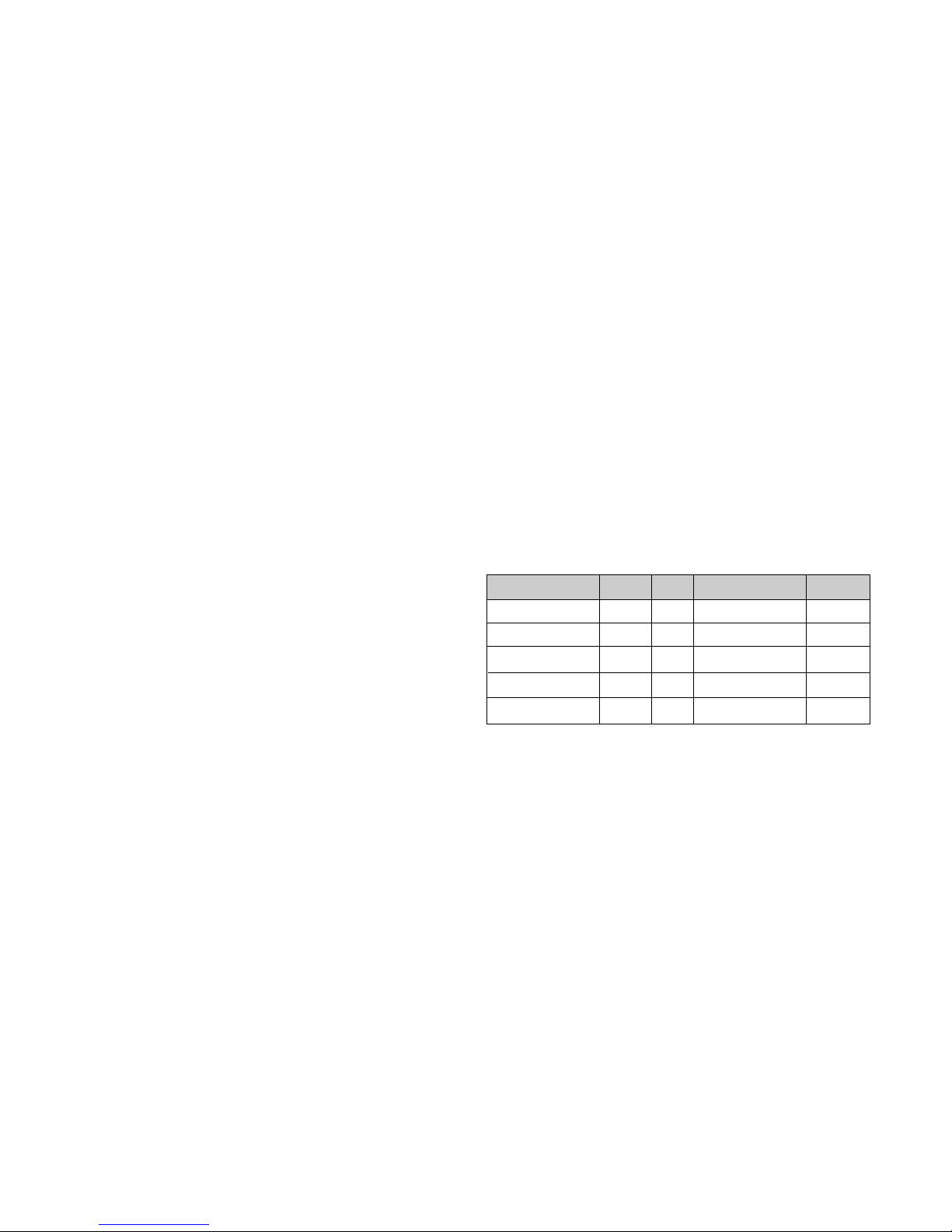
MODE
POWER ON (NORMAL)
STAND-BY
SUSPEND
OFF
POWER OFF
H/V SYNC
ON/ON
OFF/ON
ON/OFF
OFF/OFF
-
POWER CONSUMPTION
less than 30 W
less than 3 W
less than 3 W
less than 3 W
less than 3 W
LED COLOR
GREEN
ORANGE
ORANGE
ORANGE
OFF
VIDEO
ACTIVE
OFF
OFF
OFF
-
- 3 -
WARNING FOR THE SAFETY-RELATED COMPONENT.
• There are some special components used in LCD
monitor that are important for safety. These parts are
marked on the schematic diagram and the
replacement parts list. It is essential that these critical
parts should be replaced with the manufacturer’s
specified parts to prevent electric shock, fire or other
hazard.
• Do not modify original design without obtaining written
permission from LG or you will void the original parts
and labor guarantee.
TAKE CARE DURING HANDLING THE LCD MODULE
WITH BACKLIGHT UNIT.
• Must mount the module using mounting holes arranged
in four corners.
• Do not press on the panel, edge of the frame strongly
or electric shock as this will result in damage to the
screen.
• Do not scratch or press on the panel with any sharp
objects, such as pencil or pen as this may result in
damage to the panel.
• Protect the module from the ESD as it may damage the
electronic circuit (C-MOS).
• Make certain that treatment person’s body are
grounded through wrist band.
• Do not leave the module in high temperature and in
areas of high humidity for a long time.
• The module not be exposed to the direct sunlight.
• Avoid contact with water as it may a short circuit within
the module.
• If the surface of panel become dirty, please wipe it off
with a softmaterial. (Cleaning with a dirty or rough cloth
may damage the panel.)
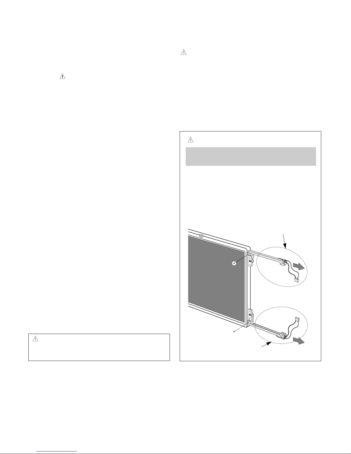
WARNING
BE CAREFUL ELECTRIC SHOCK !
• If you want to replace with the new backlight (CCFL) or
inverter circuit, must disconnect the AC adapter
because high voltage appears at inverter circuit about
650Vrms.
• Handle with care wires or connectors of the inverter
circuit. If the wires are pressed cause short and may
burn or take fire.
PRECAUTION
CAUTION
Please use only a plastic screwdriver to protect yourself
from shock hazard during service operation.
CAUTION
• There is two backlight, must distinguish between
the top (upper) and the bottom (lower), and be
careful of treatment it.
• MTBF (Mean Time Between Failure) of a backlight
is about 25,000 hours.
Top (Upper) Backlight Ass’y
(P/N: 6913TZZ001D)
Bottom (Lower) Backlight Ass’y
(P/N: 6913TZZ001E)
IF BRIGHTNESS OF THE LCD MODULE DARKEN,
REPLACE THE BACKLIGHT ONE OR ALL.
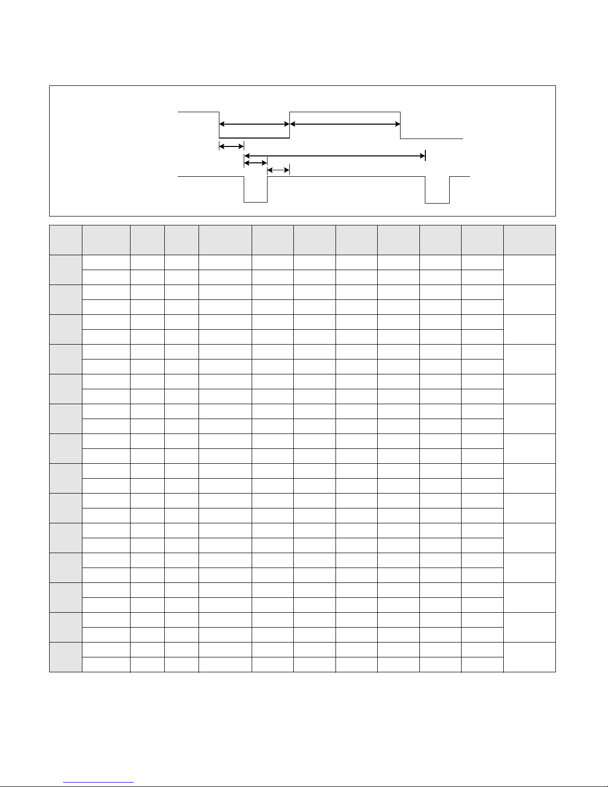
TIMING CHART
- 4 -
VIDEO
SYNC
B
D
C
F
E
A
H / V
H (Pixels)
V (Lines)
H (Pixels)
V (Lines)
H (Pixels)
V (Lines)
H (Pixels)
V (Lines)
H (Pixels)
V (Lines)
H (Pixels)
V (Lines)
H (Pixels)
V (Lines)
H (Pixels)
V (Lines)
H (Pixels)
V (Lines)
H (Pixels)
V (Lines)
H (Pixels)
V (Lines)
H (Pixels)
V (Lines)
H (Pixels)
V (Lines)
H (Pixels)
V (Lines)
Sync
Polarity
+
–
–
+
–
–
–
–
–
–
–
–
+
+
+
+
+
+
+
+
–
–
–
–
–
–
+
+
Dot
Clock
25.175
28.322
25.175
30.24
31.5
31.5
36.0
40.0
50.0
49.5
57.2832
65
75
78.75
Frequency
31.468 KHz
70.0 Hz
31.468 KHz
70.0 Hz
31.469 KHz
60.0 Hz
35.00 KHz
66.67 Hz
37.861 KHz
72.8 Hz
37.50 KHz
75.0 Hz
35.156 KHz
56.25 Hz
37.879 KHz
60.3 Hz
48.077 KHz
72.188 Hz
46.875 KHz
75.0 Hz
49.725 KHz
74.55 Hz
48.363 KHz
60.0 Hz
56.476 KHz
70.0 Hz
60.023 KHz
75.0 Hz
Resolution
640 x 350
720 x 400
(TEXT)
640 x 480
640 x 480
640 x 480
640 x 480
800 x 600
800 x 600
800 x 600
800 x 600
832 x 624
(MAC)
1024 x 768
1024 x 768
1024 x 768
Total
Period
( E )
800
449
900
449
800
525
864
525
832
520
840
500
1024
625
1056
628
1040
666
1056
625
1152
667
1344
806
1328
806
1312
800
Video
Active
Time ( A )
640
350
720
400
640
480
640
480
640
480
640
480
800
600
800
600
800
600
800
600
832
624
1024
768
1024
768
1204
768
Blanking
Time
( B )
160
99
180
49
160
45
224
45
192
40
200
20
224
25
256
28
240
66
256
25
320
43
320
38
304
38
288
32
Sync
Duration
( D )
96
2
108
2
96
2
64
3
40
3
64
3
72
2
128
4
120
6
80
3
64
3
136
6
136
6
96
3
Back
Porch
( F )
48
60
55
34
48
33
96
39
128
28
120
16
128
22
88
23
64
23
160
21
224
39
160
29
144
29
176
28
Front
Porch
( C )
16
37
17
13
16
10
64
3
24
9
16
1
24
1
40
1
56
37
16
1
32
1
24
3
24
3
16
1
MODE
1
2
3
4
5
6
7
8
9
10
11
12
13
14
+
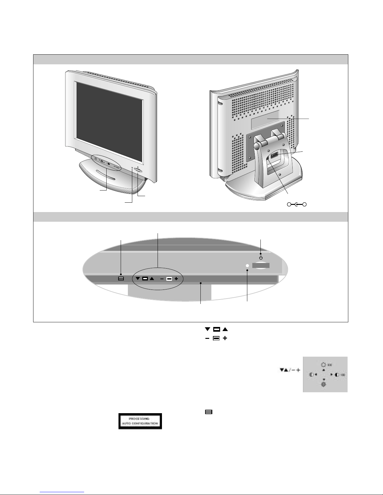
OPERATING INSTRUCTIONS
- 5 -
FRONT VIEW REAR VIEW
Front Control Panel
ID Label
Power (DPMS) Indicator
1. Power ON/OFF Button
This button is used to turn the monitor ON and OFF.
2. Power Indicator
This indicator lights up green when the monitor
operates normally; in DPMS (Energy Saving) mode,
-stand-by, suspend, or power off mode -its color
changes to orange.
3. AUTO/SET Button
Use this button to enter a selection in the on screen
display.
* AUTO adjustment function
Touch the AUTO button
before using OSD menu.
This button is for the automatic
adjustment of the screen position, clock and phase.
Note: Some signal from some graphics boards may not function
properly. If the results are unsatisfactory, adjust your
monitor’s Position, Clock and Phase manually.
4. OSD Select/Adjustment Buttons
Use these buttons to choose or adjust
items in the on screen display.
5. OSD Select/Adjustment Buttons
Use this button to enter and from the on screen display
(OSD).
Power ON/OFF Button
Front Control Panel
DC Power Connector
D-Sub
Signal Connector
-
+
AUTO/SET
5. OSD Button
3. AUTO/SET Button
1. Power ON/OFF Enter Button
2. Power (DPMS) Indicator
4. OSD Select/Adjustment Buttons
<Shortcut Keys>
• Brightness and Contrast can be adjusted
directly without entering the On Screen
Display (OSD) system. Touch the
buttons to adjust the settings and then the
OSD button to save all changes. The
Brightness and Contrast functions are also
available in the On Screen Display (OSD)
menu.
AUTO/SET
- 6 -
On-Screen-Display (OSD) Control
Making adjustments to the image size, position and operating
parameters of the monitor are quick and easy with the On
Screen Display Control system. A quick example is given below
to familiarize you with the use of the controls. Following section
is an outline of the available adjustments and selections you can
make using the OSD.
To make adjustments in the On Screen Display, follow these
steps:
NOTE
Allow the monitor to stabilize for at least 30 minutes before
making image adjustment.
/
AUTO
AUTO
1.
Press the Button, then the main menu of the
OSD appears.
2.
To acces a control, use the Buttons.
When the icon you want becomes highlighted, press
the AUTO Button.
3.
Use the Buttons to adjust
the item to the desired level.
4. Accept the changes by pressing the AUTO Button.
5.
Exit the OSD by Pressing the Button.
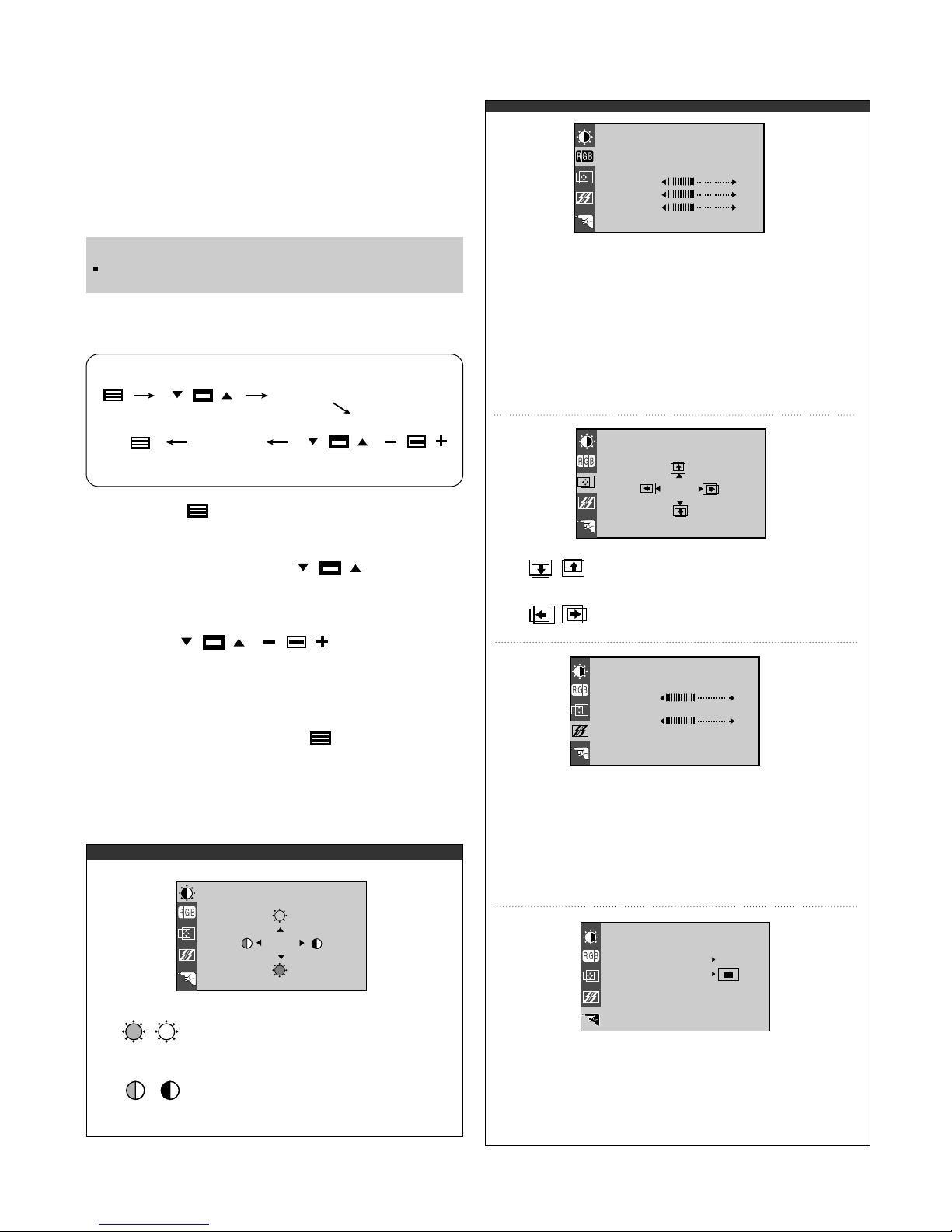
Listed below are the icons, icon names, and icon
descriptions of the items that are shown on the Menu.
Brightness
Used to adjust the brightness of the
screen.
Contrast
Adjust the display to the contrast
desired.
PRESET
RED
GREEN
BLUE
9300K/ 6500K
To appear the displays color temperature.
• 9300K:Slightly bluish white.
• 6500K:Slightly reddish white.
To set your own color levels.
To set your own color levels.
To set your own color levels.
Vertical Position
To move image up and down.
Horizontal Position
To move picture image left and right.
TRACKING
CLOCK
PHASE
LANGUAGE ENGLISH
OSD POSITION
48.3kHz / 60.0Hz
PRESET MODE
SETUP
To minimize any vertical bars or stripes
visible on the screen background.The
horizontal screen size will also change.
To adjust the focus of the display. This item
allows you to remove any horizontal noise and
clear or sharpen the image of characters.
To choose the language in which the
control names are displayed.
To adjust position of the OSD window
on the screen.
LANGUAGE
OSD POSITION
CLOCK
PHASE
COLOR
PRESET
RED
GREEN
BLUE
9300K 6500K
POSITION
61
39
BRIGHTNESS CONTRAST
88
100
- 7 -
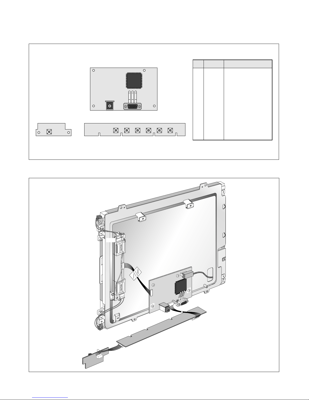
CONTROL LOCATIONS
NO.
1
2
3
4
5
6
7
Ref. No.
S9
S3
S4
S5
S6
S7
S8
Control Function
POWER SWITCH
AUTO BUTTON
OSD
+
OSD
-
OSD RIGHT
OSD LEFT
OSD ON/OFF
WIRING DIAGRAM
CN1
CN2
P1
P2
J6
CN3
J4
J5
P3
MAIN PCB
CONTROL PCB
1
234567
- 8 -
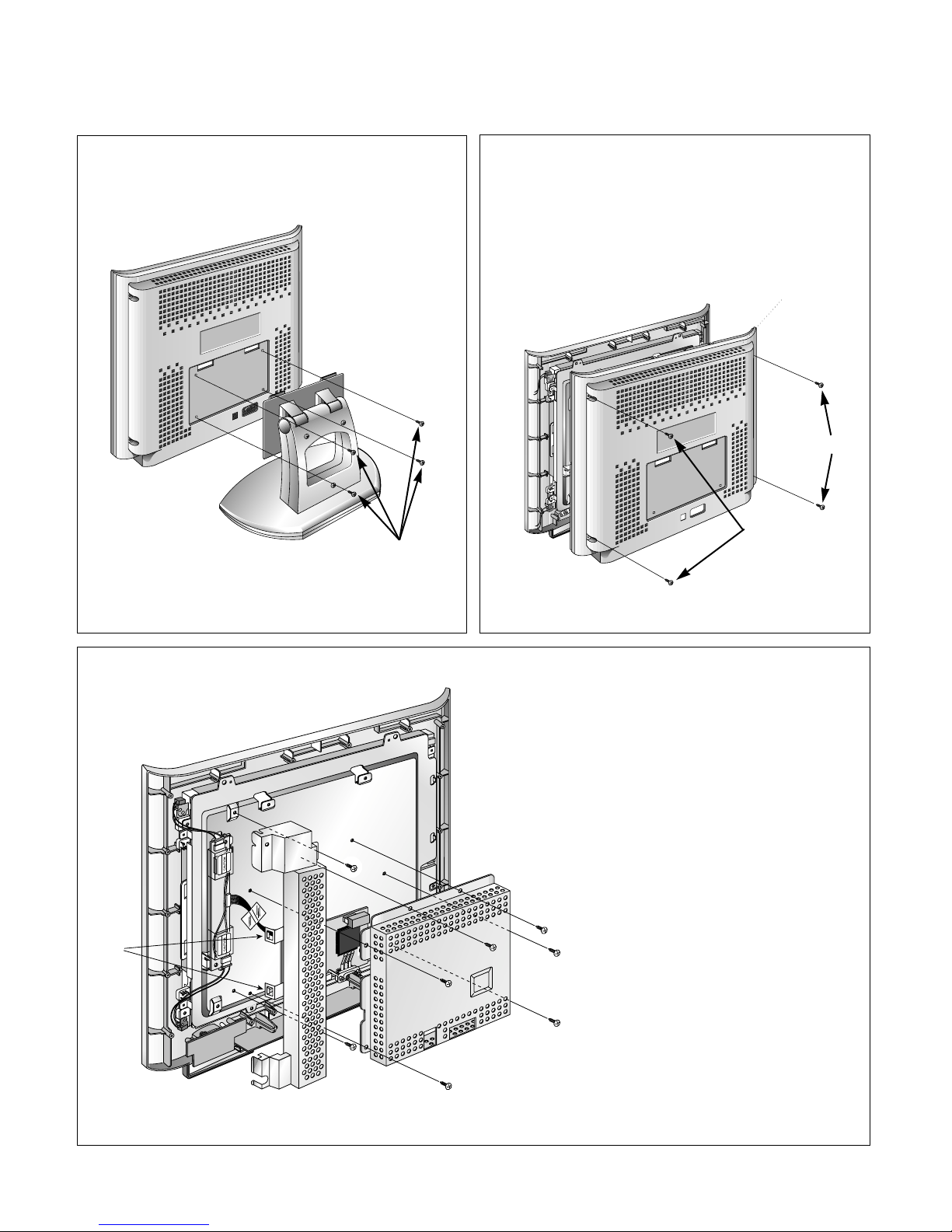
DISASSEMBLY
(a)
1. TILT/SWIVEL REMOVAL
(1) Remove four screws (a).
(2) Remove the Tilt/swivel.
2. BACK COVER REMOVAL
(1) Remove four screws (a) from the Back Cover.
(2) Remove the Back Cover.
3. TOP SHIELD & INVERTER SHIELD REMOVAL
(1) Remove six screws (a).
(2) Remove the Top Shield.
(3) Disconnect P1. (P1: See control Board)
(4) Remove two screws (b).
(5) Release two latchs (c).
(6) Remove the Inverter Shield.
(b)
(b)
(a)
(a)
(a)
(a)
(a)
(c)
(a)
(a)
(a)
Back Cover
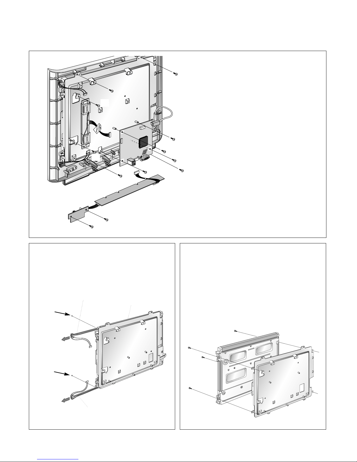
- 9 -
5. BACKLIGHT REMOVAL
(1) Remove two screws (a).
(2) Remove the Backlight from the LCD Module.
6. LCD MODULE REMOVAL
(1) Remove four screws (a).
(2) Separate the LCD Module from the Main Frame.
Bottom (Lower) Backlight Ass’y
Top (Upper) Backlight Ass’y
LCD Module
(a)
(a)
(a)
(a)
(a)
(a)
(a)
(d)
(d)
(a)
(a)
CN2
J6
CN3
J4
J5
(a)
(d)
(b)
(b)
(d)
(c)
(c)
4. INVERTER, POWER, CONTROL, AND MAIN PCB
ASSEMBLY REMOVAL
(1) Disconnect J4, J6 and J5.
(2) Remove four screws (a).
(3) Remove the Main PCB Ass’y.
(4) Disconnect CN2 and CN3.
(5) Remove two screws (b).
(6) Remove the Inverter PCB Ass’y.
(7) Remove two screws (c).
(8) Remove the Control and Power PCB Ass’y.
(9) Remove four screws (d).
(10) Remove the Front Cabinet..
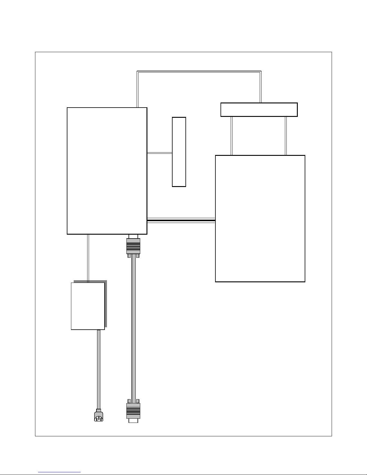
BLOCK DIAGRAM
- 10 -
POWER CORD
15-pin D-SUB SIGNAL CABLE
POWER
SUPPLY
CONTROL PCB
INVERTER PCB
MAIN LOGIC
PCB
LCD MODULE
System Block Diagram
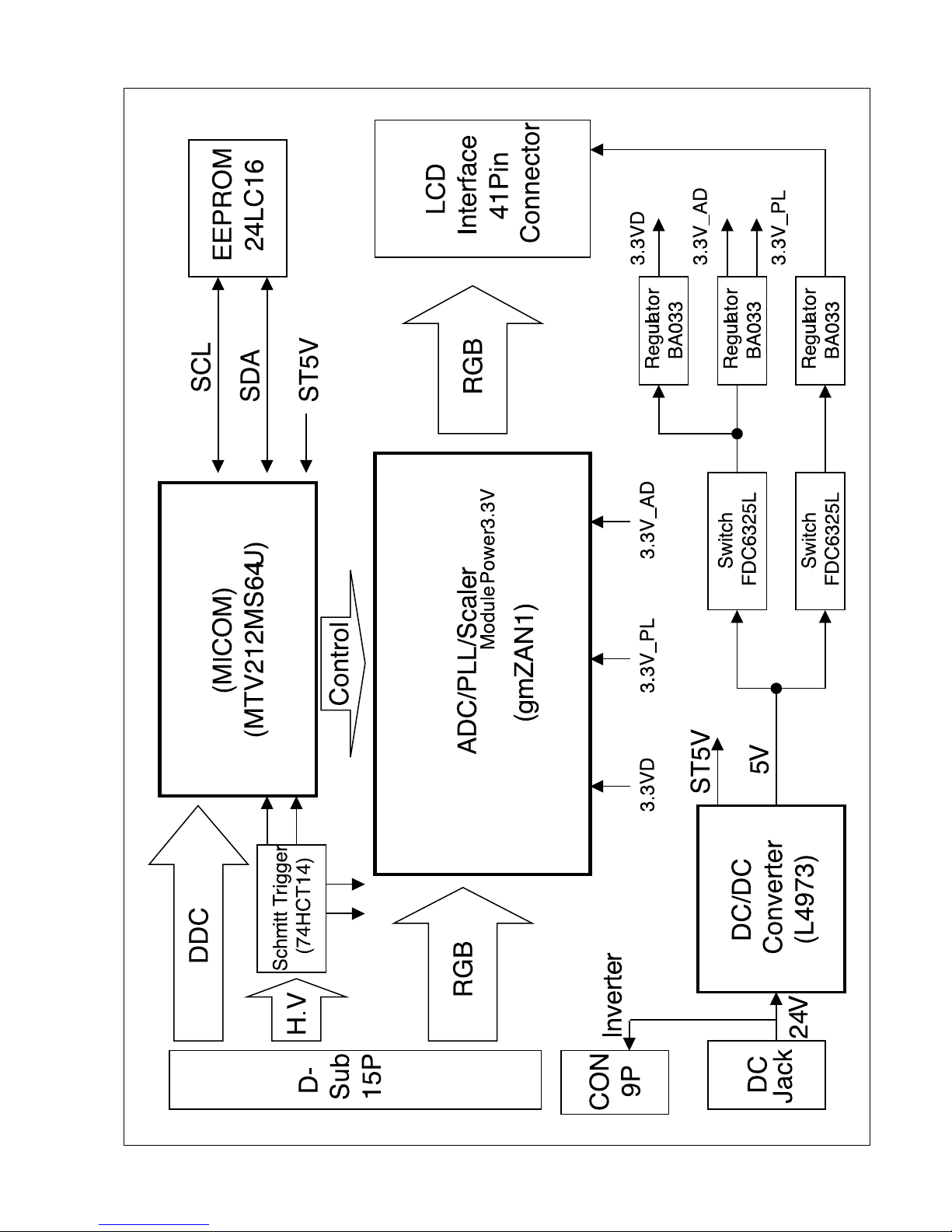
- 11 -
BLOCK DIAGRAM
 Loading...