

LG LB504N-XL Service Manual
MENU
/AUTO
SOURCE/SELECT
COLOR MONIT OR
SER VICE MANUAL
CHASSIS NO. : CL-35
F ACT OR Y MODEL: LB504N
MODEL: L1510P (LB504N-XL)
CAUTION
BEFORE SERVICING THE UNIT,
READ THE SAFETY PRECAUTIONS IN THIS MANUAL.
CONTENTS
SPECIFICATIONS
- 2 -
1. LCD CHARACTERISTICS
Type : TFT XGA LCD Module
Size : 352.0(H) x 263.5(V) x 14.0(T)
Pixel Pitch : 0.297mm x 0.297mm
Color Depth : 6Bits + FRC/ 16,194,277 colors
Active Video Area : 15.0 inch
(304.128 x 228.096)
Surface Treatment : Anti-Glare, Hard Coating (3H)
Backlight Unit : Top/Bottom edge side 2CCFL
Electrical Interface : LVDS
Interface
2. OPTICAL CHARACTERISTICS
2-1. Viewing Angle by Contrast Ratio
≥
10
Left : 55° min., 60° typ
Right : 55° min., 60° typ
Top : 40° min., 45°typ
Bottom : 40° min., 45° typ
2-2. Luminance : 200(min.), 250(typ.)
2-3. Contrast Ratio : 200(min.), 300(typ.)
3. SIGNAL (Refer to the Timing Chart)
3-1. Analog Video Input
1) Video Input Range : 0~0.7V ± 5%
2) Video Termination Impedance : 75Ω ±5%
3) Sync Type : Separate TTL, Composite TTL
SOG(Sync On Green)
4) Sync Level : TTL Low ≤ 0.8V, High ≥ 2.0V
3-2. Digital Video Input
DDWG DVI Standard 1.0
3-3. Operating Frequency
Horizontal : 31 ~ 63kHz
Vertical : 56 ~ 75Hz
4. POWER SUPPLY
4-1. Power
100~240V, 50/60Hz 0.6A
4-2. Power Consumption
5. ENVIRONMENT
5-1. Operating Temperature: 10°C~35°C (50°F~95°F)
(Ambient)
5-2. Relative Humidity : 10%~80%
(Non-condensing)
5-3. MTBF : 40,000 Hours (Min.)
Lamp Life : 40,000 Hours (min.)
6. DIMENSIONS (with TILT/SWIVEL)
Width : 356mm (14.01'')
Depth : 229mm (9.01'')
Height : 380mm (14.96'')
Width : 356mm (14.01'')
Depth : 291.4mm (11.47'')
Height : 103.3mm (4.06'')
7. WEIGHT (with TILT/SWIVEL)
Net. Weight : 5.0kg (11.02 lbs)
Gross Weight : 6.6kg (14.55 lbs)
SPECIFICATIONS ................................................... 2
PRECAUTIONS ....................................................... 3
TIMING CHART ....................................................... 4
OPERATING INSTRUCTIONS ................................ 5
WIRING DIAGRAM ................................................. 8
BLOCK DIAGRAM ................................................... 9
DESCRIPTION OF BLOCK DIAGRAM................... 11
ADJUSTMENT ...................................................... 13
TROUBLESHOOTING GUIDE .............................. 14
PRINTED CIRCUIT BOARD................................... 18
EXPLODED VIEW...................................................21
REPLACEMENT PARTS LIST ...............................23
PIN CONFIGURATION............................................28
SCHEMATIC DIAGRAM......................................... 32
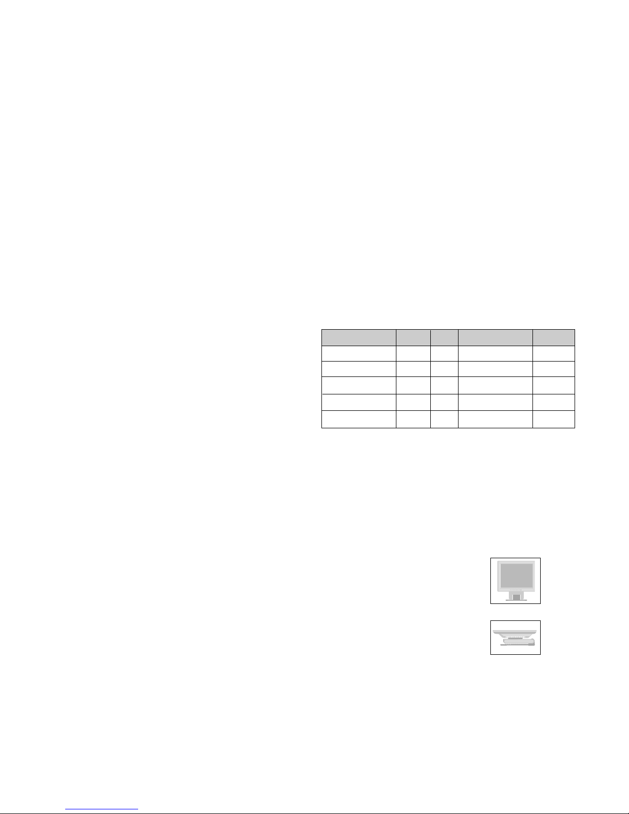
MODE
POWER ON (NORMAL)
STAND-BY
SUSPEND
DPMS OFF
POWER OFF
H/V SYNC
ON/ON
OFF/ON
ON/OFF
OFF/OFF
POWER CONSUMPTION
less than 30 W
less than 3 W
less than 3 W
less than 3 W
less than 3 W
LED COLOR
GREEN
AMBER
AMBER
AMBER
OFF
VIDEO
ACTIVE
OFF
OFF
OFF
- 3 -
WARNING FOR THE SAFETY-RELATED COMPONENT.
• There are some special components used in LCD
monitor that are important for safety. These parts are
marked on the schematic diagram and the
replacement parts list. It is essential that these critical
parts should be replaced with the manufacturer’s
specified parts to prevent electric shock, fire or other
hazard.
• Do not modify original design without obtaining written
permission from manufacturer or you will void the
original parts and labor guarantee.
TAKE CARE DURING HANDLING THE LCD MODULE
WITH BACKLIGHT UNIT.
• Must mount the module using mounting holes arranged
in four corners.
• Do not press on the panel, edge of the frame strongly
or electric shock as this will result in damage to the
screen.
• Do not scratch or press on the panel with any sharp
objects, such as pencil or pen as this may result in
damage to the panel.
• Protect the module from the ESD as it may damage the
electronic circuit (C-MOS).
• Make certain that treatment person’s body are
grounded through wrist band.
• Do not leave the module in high temperature and in
areas of high humidity for a long time.
• The module not be exposed to the direct sunlight.
• Avoid contact with water as it may a short circuit within
the module.
• If the surface of panel become dirty, please wipe it off
with a softmaterial. (Cleaning with a dirty or rough cloth
may damage the panel.)
WARNING
BE CAREFUL ELECTRIC SHOCK !
• If you want to replace with the new backlight (CCFL) or
inverter circuit, must disconnect the AC adapter
because high voltage appears at inverter circuit about
650Vrms.
• Handle with care wires or connectors of the inverter
circuit. If the wires are pressed cause short and may
burn or take fire.
PRECAUTION
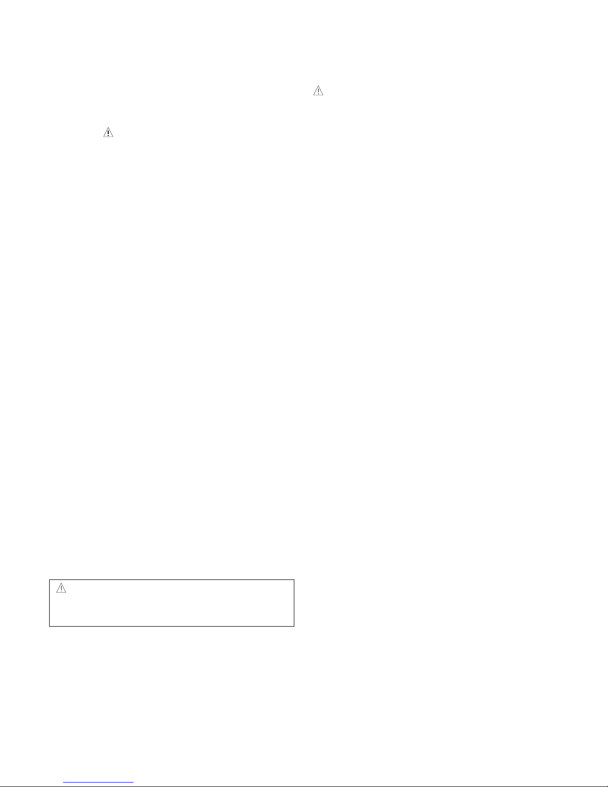
CAUTION
Please use only a plastic screwdriver to protect yourself
from shock hazard during service operation.
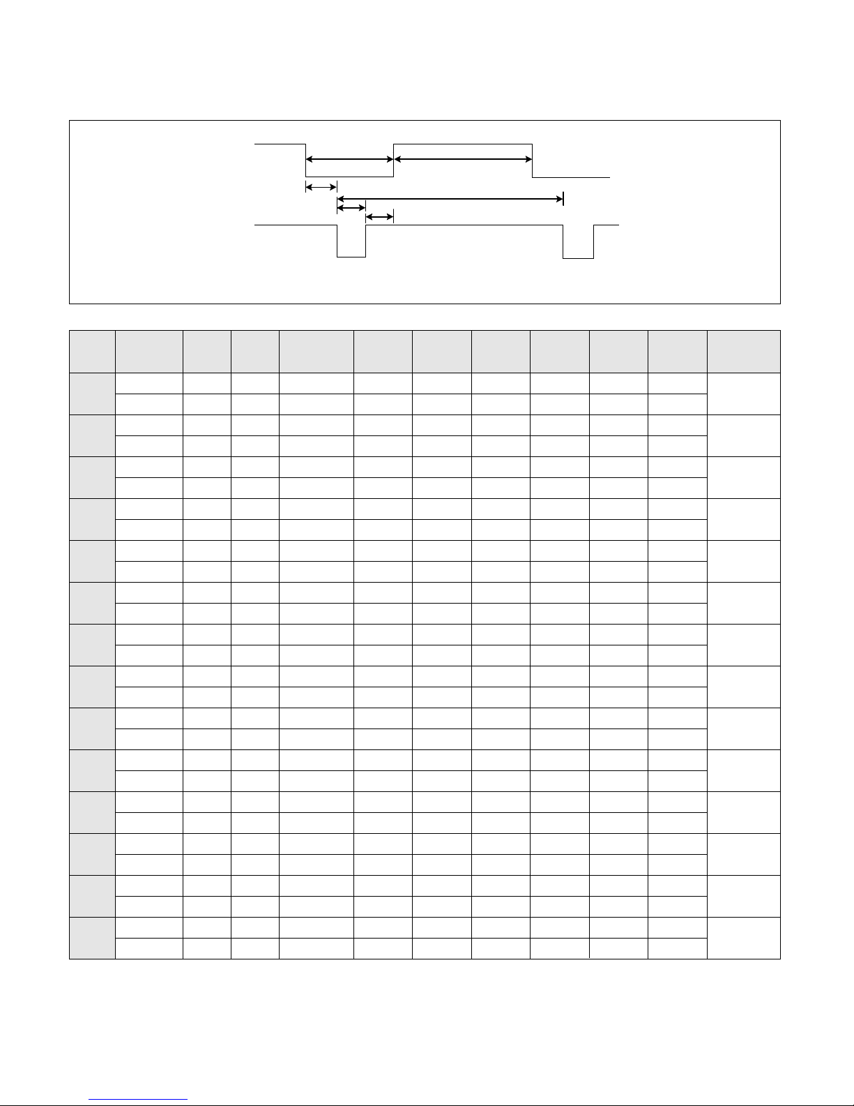
TIMING CHART
- 4 -
VIDEO
SYNC
B
D
C
F
E
A
H / V
H (Pixels)
V (Lines)
H (Pixels)
V (Lines)
H (Pixels)
V (Lines)
H (Pixels)
V (Lines)
H (Pixels)
V (Lines)
H (Pixels)
V (Lines)
H (Pixels)
V (Lines)
H (Pixels)
V (Lines)
H (Pixels)
V (Lines)
H (Pixels)
V (Lines)
H (Pixels)
V (Lines)
H (Pixels)
V (Lines)
H (Pixels)
V (Lines)
H (Pixels)
V (Lines)
Sync
Polarity
+
–
–
+
–
–
–
–
–
–
–
–
+
+
+
+
+
+
+
+
–
–
–
–
–
–
+
+
Dot
Clock
25.175
28.322
25.175
30.24
31.5
31.5
36.0
40.0
50.0
49.5
57.2832
65
75
78.75
Frequency
31.468 KHz
70.0 Hz
31.468 KHz
70.0 Hz
31.469 KHz
60.0 Hz
35.0 KHz
66.67 Hz
37.861 KHz
72.8 Hz
37.50 KHz
75 Hz
35.156KHz
56.25 Hz
37.879 KHz
60.3 Hz
48.077 KHz
72.188 Hz
46.875 KHz
75.0 Hz
49.725 KHz
74.55 Hz
48.363 KHz
60.0 Hz
56.476 KHz
70.0 Hz
60.023 KHz
75.0 Hz
Resolution
640 x 350
720 x 400
640 x 480
640 x 480
640 x 480
640 x 480
800 x 600
800 x 600
800 x 600
800 x 600
832 x 624
1024 x 768
1024 x 768
1024 x 768
Total
Period
( E )
800
449
900
449
800
525
864
525
832
520
840
500
1024
625
1056
628
1040
666
1056
625
1152
667
1344
806
1328
806
1312
800
Video
Active
Time ( A )
640
350
720
400
640
480
640
480
640
480
640
480
800
600
800
600
800
600
800
600
832
624
1024
768
1024
768
1024
768
Blanking
Time
( B )
160
99
180
49
160
45
224
45
192
40
200
20
224
25
256
28
240
66
256
25
320
43
320
38
304
38
288
32
Sync
Duration
( D )
96
2
108
2
96
2
64
3
40
3
64
3
72
2
128
4
120
6
80
3
64
3
136
6
136
6
96
3
Back
Porch
( F )
48
60
55
34
48
33
96
39
128
28
120
16
128
22
88
23
64
23
160
21
224
39
160
29
144
29
176
28
Front
Porch
( C )
16
37
17
13
16
10
64
3
24
9
16
1
24
1
40
1
56
37
16
1
32
1
24
3
24
3
16
1
MODE
1
2
3
4
5
6
7
8
9
10
11
12
13
14
(MAC)
(TEXT)
OPERATING INSTRUCTIONS
MENU
/AUTO
SOURCE/SELECT
100
100
PROCESSING
AUTO CONFIGURATION
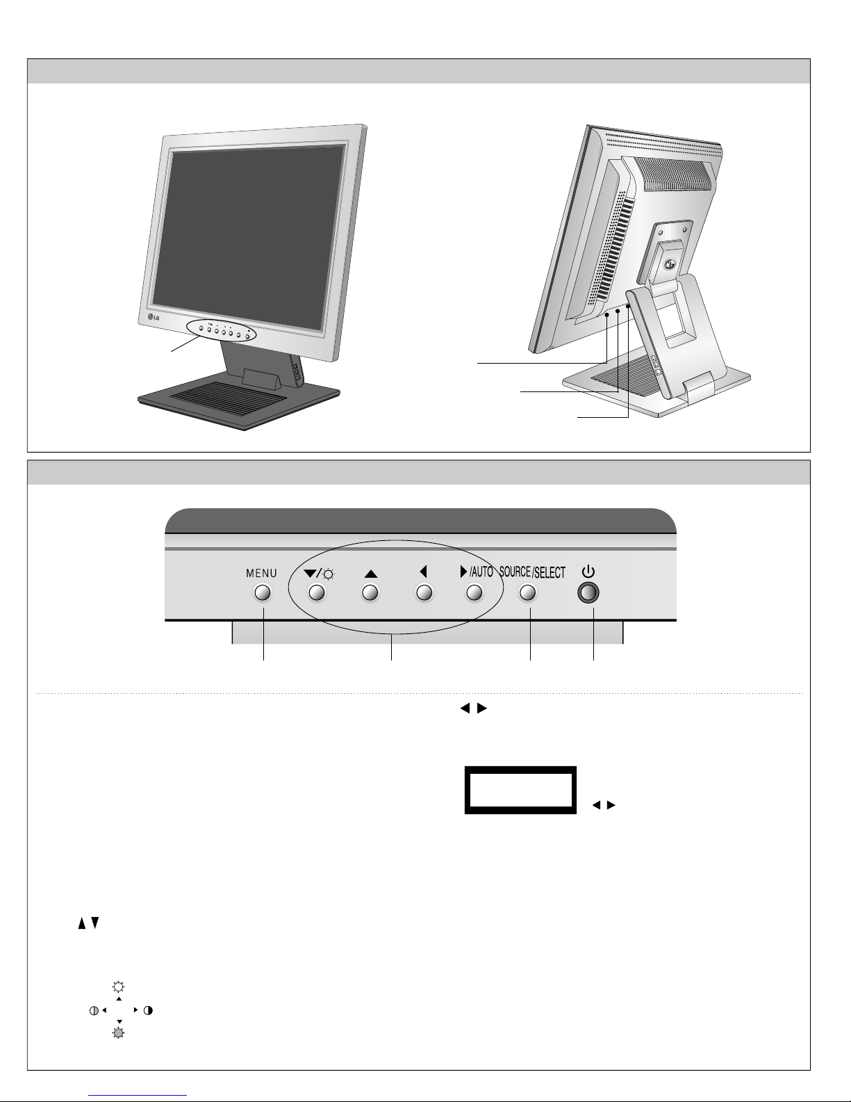
FRONT VIEW
See front control panel
REAR VIEW
Power Connector
D-Sub Signal Connector
DVI-l Connector
Front Control Panel
1. Power Button
Use this button to turn the display on or off.
<Power (DPMS) Indicator>
This Indicator lights up green when the display
operates normally. If the display is in DPM (Energy
Saving) mode, this indicator color changes to
amber.
2. Menu Button
Use this button to enter or exit the On Screen
Display.
3. Button
Use these buttons to choose or adjust items in the
On Screen Display.
Bring up Contrast and
Brightness adjustment.
1142 3
4. Button
Use these buttons to choose or adjust items in the
On Screen Display.
When adjusting your display
settings, always press the
button before entering the
On Screen Display(OSD). This
will automatically adjust your display image to the
ideal settings for the current screen resolution size
(display mode). The best display mode is 1024x768.
SOURCE/SELECT Button
5.
Use this button to enter a selection in the On
Screen Display.
When selecting input signal, press Source/Select
button before entering the OSD. This will change
input(DVI-I/D-SUB select button). The Default
setting is D-SUB.
6. Control Lock(Menu button, button)
CONTROLS LOCKED
CONTROLS UNLOCKED
Press the hold the MENU button and button for
3 seconds: the message “CONTROLS LOCKED”
appears.
You can unlock the OSD controls at any time by
pushing the MENU, button for 3 seconds:
the message “CONTROLS UNLOCKED” will
appear.
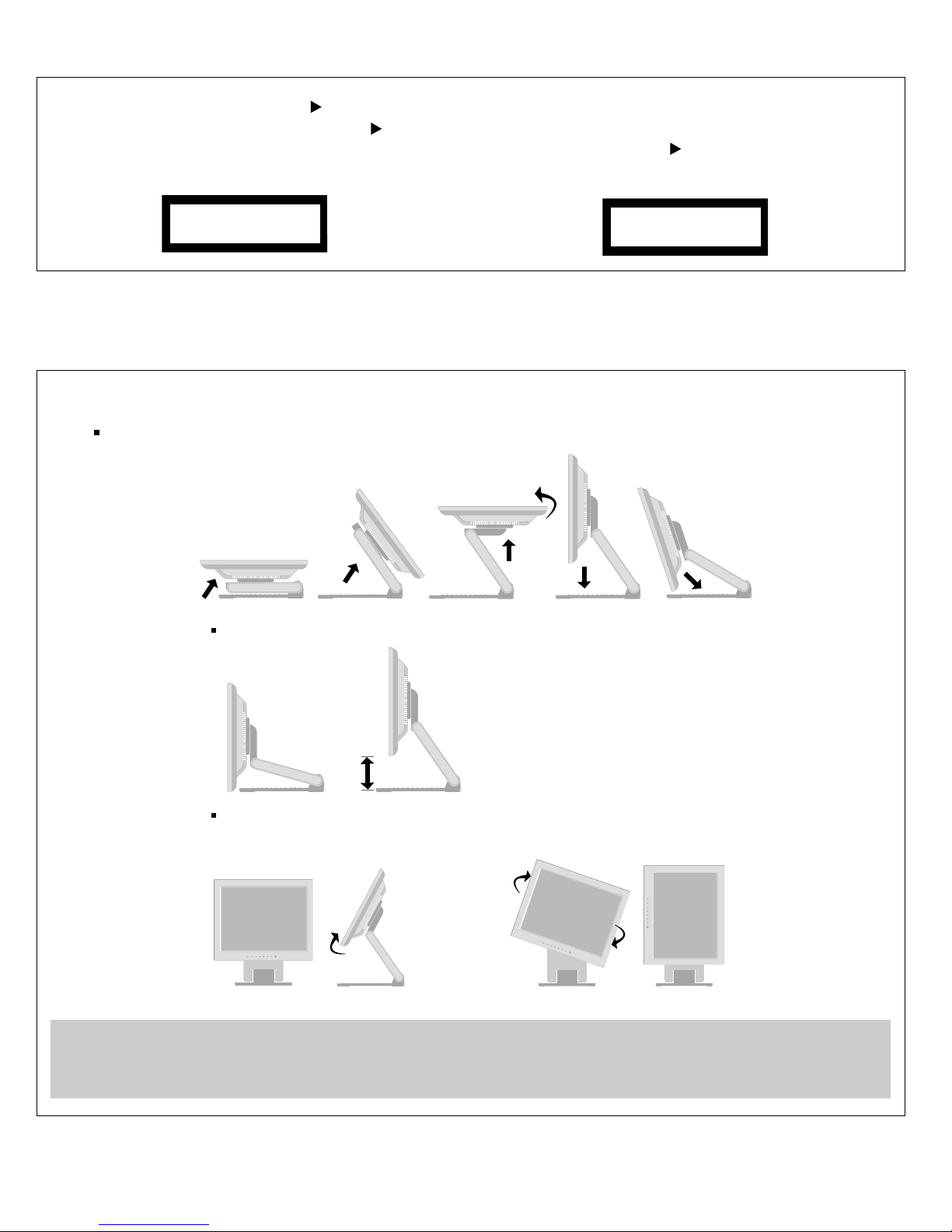
Positioning your display
※ Adjust the position of the panel in various ways for maximum comfort.
Tilt Range : -24˚~145˚
145˚ -24˚
Height Range : maximun 3.39inch (86.1mm)
Landscape & Portrait : You can rotate the panel 90
o
clockwise.
(* For detailed information, please refer to the Pivot Sofeware CD provided.)
* Make sure not to
touch the floor
when the head
rotates to use the
Pivot function.
Ergonomic
It is recommended that in order to maintain an ergonomic and comfortable viewing position, the forward tilt angle of the monitor should
not exceed 5 degrees.
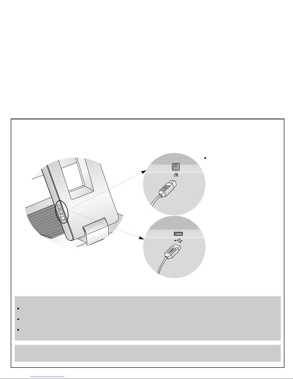
Making use of USB (Universal Serial Bus)*
USB (Universal Serial Bus) is an innovation in connecting your different desktop peripherals conveniently to your computer.
By using the USB, you will be able to connect your mouse, keyboard, and other to your monitor instead of having to
connect them to your computer. This will give you greater flexibility in setting up your system. USB allows you to connect
chain up to 120 devices on a single USB port, and you can “hot” plug (attach them while the computer is running) or unplug
them while maintaining Plug and Plug auto detection and configuration. This monitor has an integrated BUS-powered USB
hub, allowing up to 2 other USB devices to be attached it.
USB connection
1. Connect the upstream port of the Display to the downstream port of the USB compliant PC or another hub using the
USB cable. (Computer must have a USB port)
2. Connect the USB compliant peripherals to the downstream ports of the monitor.
This is a simplified representation
of rear view.
To USB downstream port
of the USB compliant PC or
another hub cable
USB downstream Port
connect the cables from USB
compliant peripherals-such as
keyboard, mouse, etc
NOTE
To activate the USB hub function, the monitor must be connected to a USB compliant PC(OS) or another hub with the USB
cable(enclosed).
When connecting the USB cable, check that the shape of the connector at the cable side matches the shape at the connecting
side.
Even if the monitor is in a power saving mode, USB compliant devices will function when they are connected the USB ports(both
the upstream and downstream) of the monitor.
IMPORTANT: These USB connectors are not designed for use with high-power USB devices such as a video camera, scanner, etc.
LGE recommends connecting high-power USB devices directly to the computer.
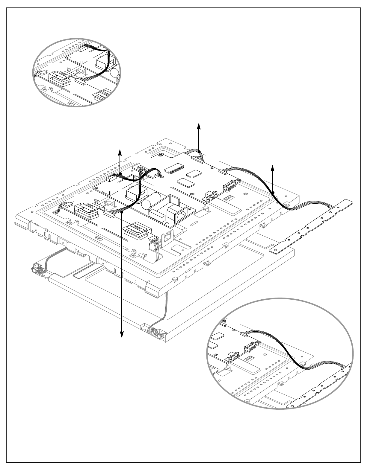
P902
J1
CN1
CN3
CN2
J702
J704
J705
J501
P902
CN1
CN2
J1
J702
J501
Connector the Main PCB Ass’y and Inverter.
Connector Ass’y :
P/N: 6631T20008G
Connector Ass’y :
P/N: 6631T11012R
Connector Ass’y :
P/N: 6631T12002H
Connector Ass’y :
P/N: 6631T20015P
Connector the Control PCB Ass’y and Main PCB Ass’y.
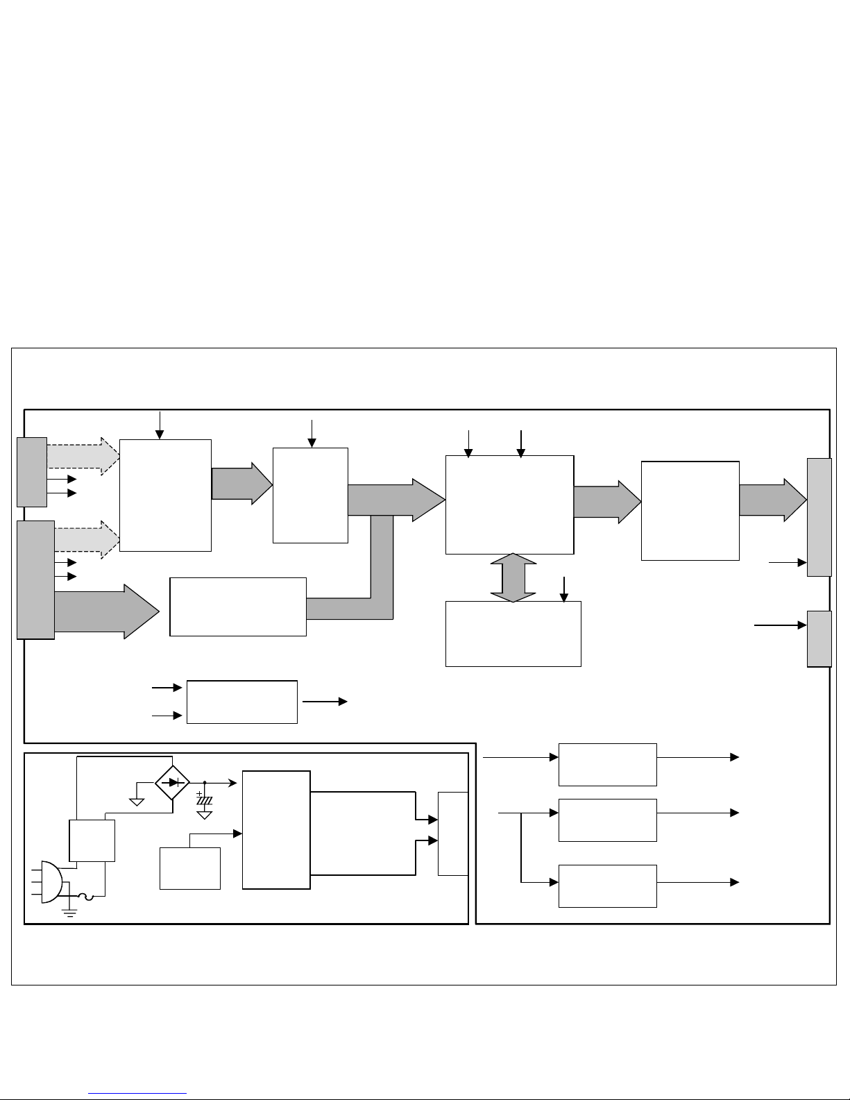
Filter
BD
SMPS
Control
IC
TOP247
12V
5V
CON 5P
To main
D-Sub
DVI-I
R2/G2/B2
R1/G1/B1
R/G/B
Selection
(BA7657)
R/G/B
ADC IC
(AD9884)
Scaler IC
(MX88L250EC-X)
TMDS Receiver IC
(SIL141B)
Digital
Signal
LVDS IC
(THC63LVDM83R)
MICOM
( MTV312)
3.3 V
Regulator
2.5 V
Regulator
5 V
Regulator
12V 5VR
5V
3.3V
2.5V
3.3V 2.5V
RGB Data
3.3V
12V
Inverter
8Pin
MODULE
5VR
H/V Selection
Gate
H1
V1
H2
V2
H1/V1
H2/V2
H/V
3.3V
5VR
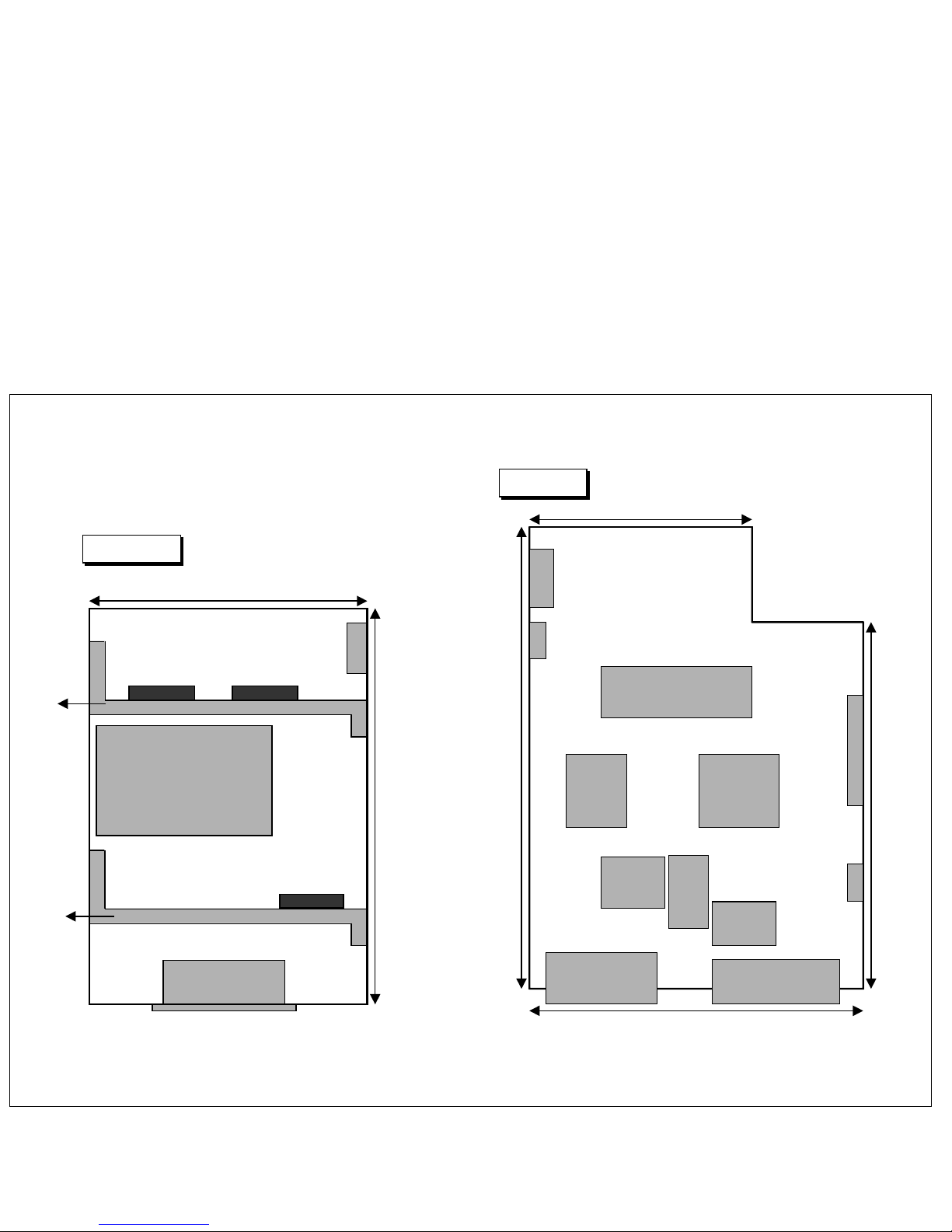
AC Inlet
SMPS Trans
Power 5Pin
Regulator
44mm
135mm
Power PCB
Main PCB
Control IC
Heat
sink
Heat
sink
64mm
120mm
150
mm
101mm
Power 5Pin
Inverter 8Pin
Control
6 pin
LCD Module
20 pin
D-Sub DVI-I
MICOM
Scaler
ADC
R/G/B
Selection
ADC
TMDS
Receiver

DESCRIPTION OF BLOCK DIAGRAM
- 11 -
1. Input signal switching part(BA7657).
There are two analog inputs which are analog and digital input.
They come from each 15 pin D-Sub and 24 pin DVI-I connector.
2. Video Controller Part.
This part amplifies the level of video signal for the digital conversion and converts from the analog video signal
to the digital video signal using a pixel clock.
The pixel clock for each mode is generated by the PLL.
The range of the pixel clock is from 25MHz to 80MHz.
This part consists of the Scaler, ADC and TMDS receiver .
The Scaler gets the video signal converted analog to digital, interpolates input to 1024 X 768 resolution signal
and outputs 8-bit R, G, B signal to transmitter.
3. Display Data Transmitter Part(LVDS).
This part transmit digital signal from the Scaler to the receiver of module.
4. Power Part.
This part consists of the one 5V, two 3.3V, and one 2.5V regulators to convert power which is provided 12V,
5V in Power board.
3.3V is provided for LCD panel and inverter, 5V is provided for micom and analog selection(BA7657).
Also, 5V is converted 3.3V and 2.5V by regulator. Converted power is provided for IC in the main board.
5. MICOM Part.
This part consists of EEPROM IC which stores control data, Reset IC and the Micom.
The Micom distinguishes polarity and frequency of the H/V sync are supplied from signal cable.
The controlled data of each modes is stored in EEPROM.
6. Inverter
The inverter converts from DC12V to AC 700Vrms and operate back-light lamp of module.
- 12 -
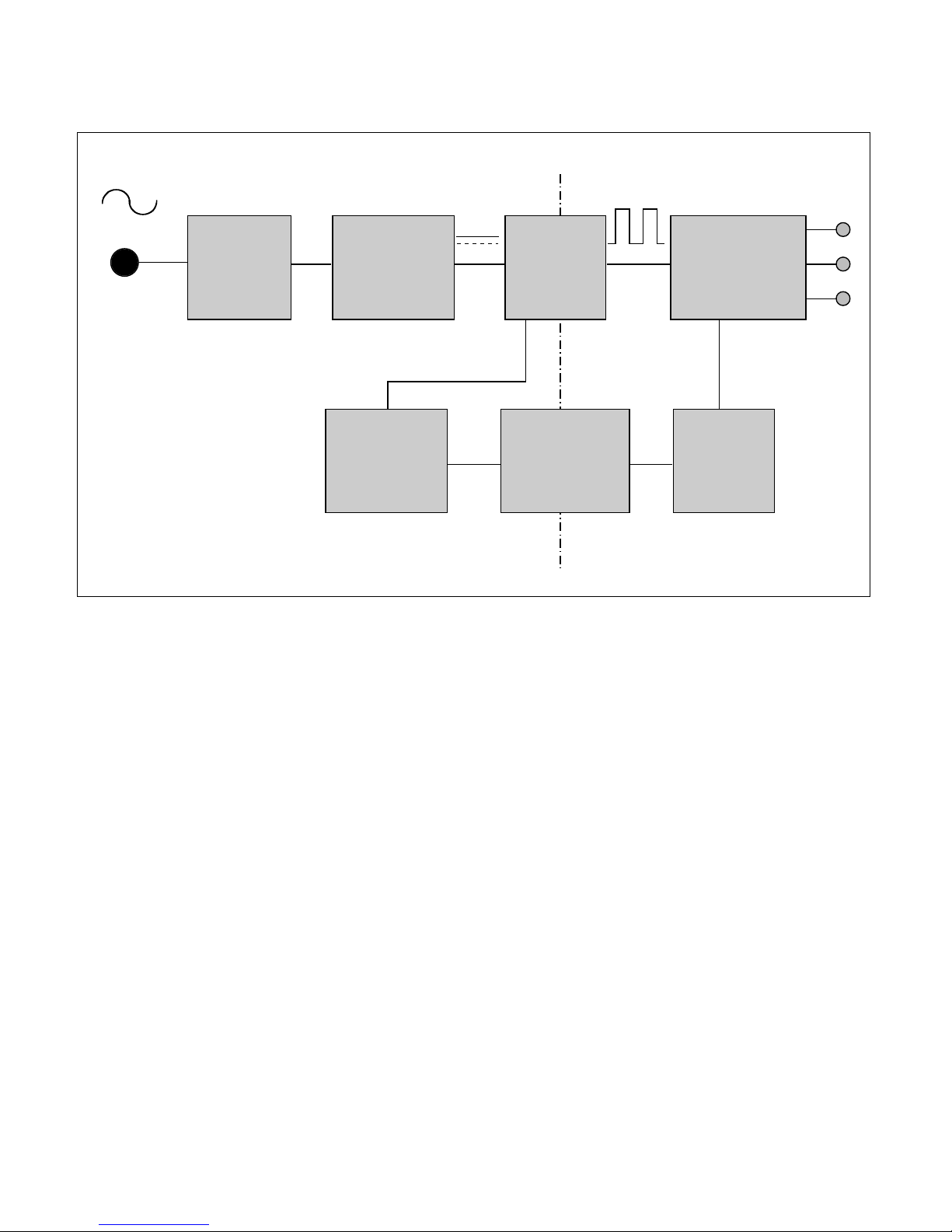
POWER BLOCK DIAGRAM
EMI
COMPONENTS
LINE
100 ~ 240V
INPUT RECTIFIER
AND FILTER
ENERGY
TRANSFER
OUTPUT RECTIFIER
AND FILTER
12V
5V
GND
SIGNAL
COLLENTION
PHOTO-COUPLER
ISOLATION
PWM CONTRO
L
CIRCUIT
HVDC
100KHz
PRIMARY
SECONDARY
50 ~ 60Hz
1. EMI components.
This part contains of EMI components to comply with global marketing EMI standards like FCC, VCCI CISPR,
the circuit included a line-filter, across line capacitor and of course the primary protection fuse.
2. Input rectifier and filter.
This part function is for transfer the input AC voltage to a DC voltage through a bridge rectifier and a bulk
capacitor.
3. Energy Transfer.
This part function is transfer the primary energy to secondary through a power transformer.
4. Output rectifier and filter.
This part function is to make a pulse width modulation control and to provide the driver signal to power switch,
to adjust the duty cycle during different AC input and output loading condition to achive the dc output stablize,
and also the over power protection is also monitor by this part.
5. Photo-Coupler isolation.
This part function is to feed back the dc output changing status through a photo transistor to primary controller
to achive the stablized dc output voltage.
6. Signal collection.
This part function is to collect the any change from the dc output and feed back to the primary through photo
transistor
DESCRIPTION OF BLOCK DIAGRAM
- 13 -
ADJUSTMENT
All adjustment are thoroughly checked and corrected
when the monitor leaves the factory, but sometimes
several minor adjustment may be required.
Adjustment should be following procedure and after
warming up for a minimum of 10 minutes.
Alignment appliances and tools.
- IBM Compatible PC
- Programmable Signal Generator.
(eg. VG-819 made by Astrodesign Co.)
- E(E)PROM with each mode data saved.
- Alignment Adapter and Software.
1. Adjustment for Factory Preset Mode
1) Run alignment program for LB504N on the IBM
compatible PC.
2) Select EEPROM All Init. command and Enter.
3) Display cross hatch pattern at Mode 1.
4) Select EDID WRITE command and Enter.
2. Adjustment for White Balance
1) Display color 0,0 pattern at Mode 13.
2) Set External Bright to MAX position and Contrast to
MAX Position.
3) Select PRESET START → BIAS CAL command
and Enter.
4) No attempt to manually adjust, BIAS data is automatically adjusted and saved to the EEPROM.
5) Display color 15,0 pattern at Mode 13.
6) Select DRIVE CAL command and Enter.
7) Color 1 (9300K) and Color 2 (6500K) are
automatically adjusted and saved to the EEPROM.
8) Select PRESET EXIT command and Enter.
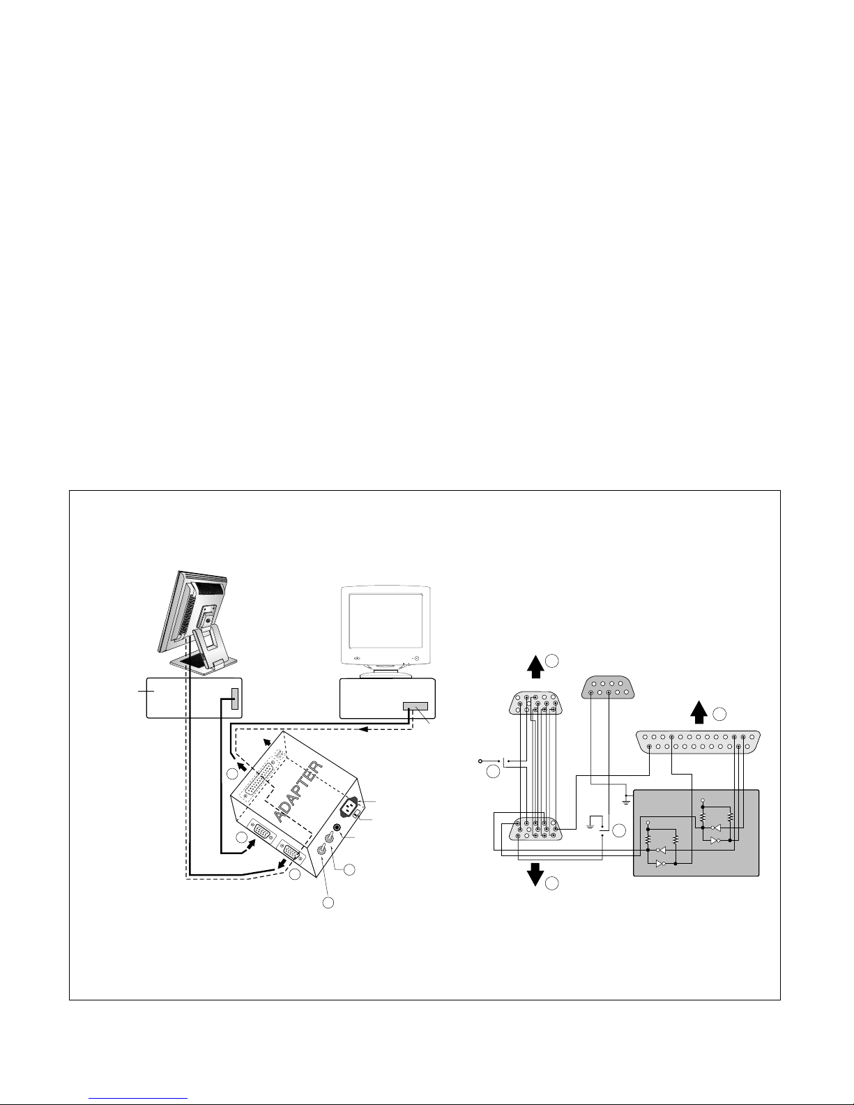
Figure 1. Cable Connection
220
IBM
Compatible PC
PARALLEL PORT
Power inlet (required)
Power LED
ST Switch
Power Select Switch
(110V/220V)
Control Line
Not used
RS232C
PARALLEL
V-SYNC
POWER
ST
VGS
MONITOR
E
E
V-Sync On/Off Switch
(Switch must be ON.)
F
F
A
A
B
B
C
C
15
10
5
5
69
1
1
1
14
13
25
6
5V
5V
5V
4.7K
4.7K
4.7K
74LS06
74LS06
OFF ON
OFF
ON
11
Video Signal
Generator
 Loading...