

Lg Lauk2430hl Installation Guide
INSTALLATION INSTRUCTIONS
SINGLE SPLIT WALL MOUNTED AIR CONDITIONER
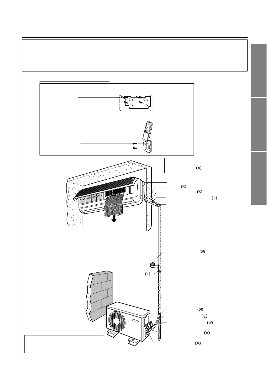
1. Type "A" screw
2. Installation Plate
3. Type "B" screw
4. Holder Remote Control
Air filter
Installation plate
Sleeve
Bushing-Sleeve
Putty(Gum Type Sealer)
Bend the pipe as closely
on the wall as possible,
but be careful that it
doesn't break.
Installation parts you
must purchase
Vinyl tape (Wide)
• Apply after carrying out a
drainage test.
• To carry out the drainage
test, remove the air filters
and pour water into the heat
exchanger.
Saddle
Gas side piping (Optional Parts)
Liquid side piping (Optional Parts)
Additional drain pipe
Vinyl tape (Narrow)
Connecting cable
(Optional Parts)
P/No.: 3828A20196X
(Split - Series)
• Please read this instruction sheet completely before installing the product.
• When the power cord is damaged, replacement work shall be performed by authorized
personnel only.
• Installation work must be performed in accordance with the national wiring standards by
authorized personnel only.
Installation Parts Provided
• This illustration is for explanation purposes only.
• The indoor unit will actually face a different way.
• Copper lines must be insulated independently.
ENGLISH FRANÇAIS ESPAÑOL

INSTALLATION OVERVIEW
2
The following should be always
observed for safety
....................
3
Installation of indoor, outdoor
unit
................................................
4
Flaring work and connection of
piping
...........................................
6
Connection of piping(Indoor)
......
7
For right rear piping
For left rear piping
Connection of piping(Outdoor)
................................................
10
Connecting the cable between
indoor unit and outdoor unit
......
....................................................
11
Checking the drainage and
Forming the piping
..................
14
Air purging
...............................
15
Test running
.............................
17
❏ Installation plate
❏Four type "A" screws
❏Connecting cable
❏
Pipes: Gas side .........1/2"(9K,12K)
5/8"(18K,24K)
Liquid side......1/4"(9K,12K,18K)
3/8"(24K)
(Refer to page 4)
❏Insulation materials
❏Additional drain pipe
(Outer Diameter.........15.5mm)
❏Level gauge
❏Screw driver
❏Electric drill
❏Hole core drill ø70mm(2.79")
❏Flaring tool set
❏Specified torque wrenches
Liquid side -1.8kg.m(13ft.lbs):9K,12K,18K
4.0kg.m(28.9ft.lbs):24K
Gas side - 5.5kg.m(39.8ft.lbs):9K, 12K
6.6kg.m(47.7ft.lbs):18K, 24
K
❏Spanner......................Half union
❏A glass of water
❏Screw driver
❏Hexagonal wrench(4mm: 5.32")
❏Gas-leak detector
❏Vacuum pump
❏Gauge manifold
❏Owner's manual
❏Thermometer
❏Holder Remote Control
Installation
Requirements
Required Parts Required Tools
ENGLISH
THE FOLLOWING SHOULD BE ALWAYS OBSERVED FOR SAFETY
3
■
Be sure to read "THE FOLLOWING SHOULD BE ALWAYS OBSERVED FOR SAFETY" before installing the air
conditioner.
■
Be sure to observe the cautions specified here as they include important items related to safety.
■
The indications and meanings are as follows.
■
After reading this instructions, be sure to keep it together with the owner's manual in a handy place on the
customer's site.
WARNING
: Could lead to death, serious injury, etc.
CAUTION
: Could lead to serious injury in particular environments when operated
incorrectly.
WARNING
Incorrect installation could cause injury due to fire,
electric shock, the unit falling or leakage of water.
Consult the dealer from whom you purchased the
unit or special installer.
Do not install it yourself (customer).
When installed in an insufficiently strong place,
the unit could fall causing injury.
Install the unit securely in a place which can bear
the weight of the unit's.
Incorrect connection and attachment could cause fire.
Use the specified wires to connect the indoor and
outdoor units securely and attach the wires firmly
to the terminal board connecting sections so the
stress of the wires is not applied to the sections.
If the electrical part covers of the indoor unit
and/or the service panel of the outdoor unit are
not attached securely, it could result in a fire or
electric shock due to dust, water, etc.
Attach the electrical part cover to the indoor unit
and the service panel to the outdoor unit securely.
The use of defective parts could cause an injury
due to a fire, electric shock, the unit's falling, etc.
Be sure to use the part provided or specified parts
for the installation work.
Check that the refrigerant gas does not leak after
installation is completed.
Incorrect installation could cause a personal
injury due to fire, electric shock, the unit falling
or leakage of water.
Perform the installation securely referring to the
installation instruction.
If the capacity of the power circuit is insufficient
or there is incomplete electrical work, it could
result in a fire or an electric shock.
Perform electrical work according to the installation
manual and be sure to use a dedicated circuit.
CAUTION
If there is a defect in the drainage/piping work,
water could leak from the unit and household
goods could come wet and be damaged.
Perform the drainage/piping work according
to the installation instruction.
If gas leaks and accumulates in the area
surrounding the unit, it could cause an explosion.
Do not install the unit in a place where a
flammable gas leaks.
4
INSTALLATION OF INDOOR, OUTDOOR UNIT
Read completely, then follow step by step.
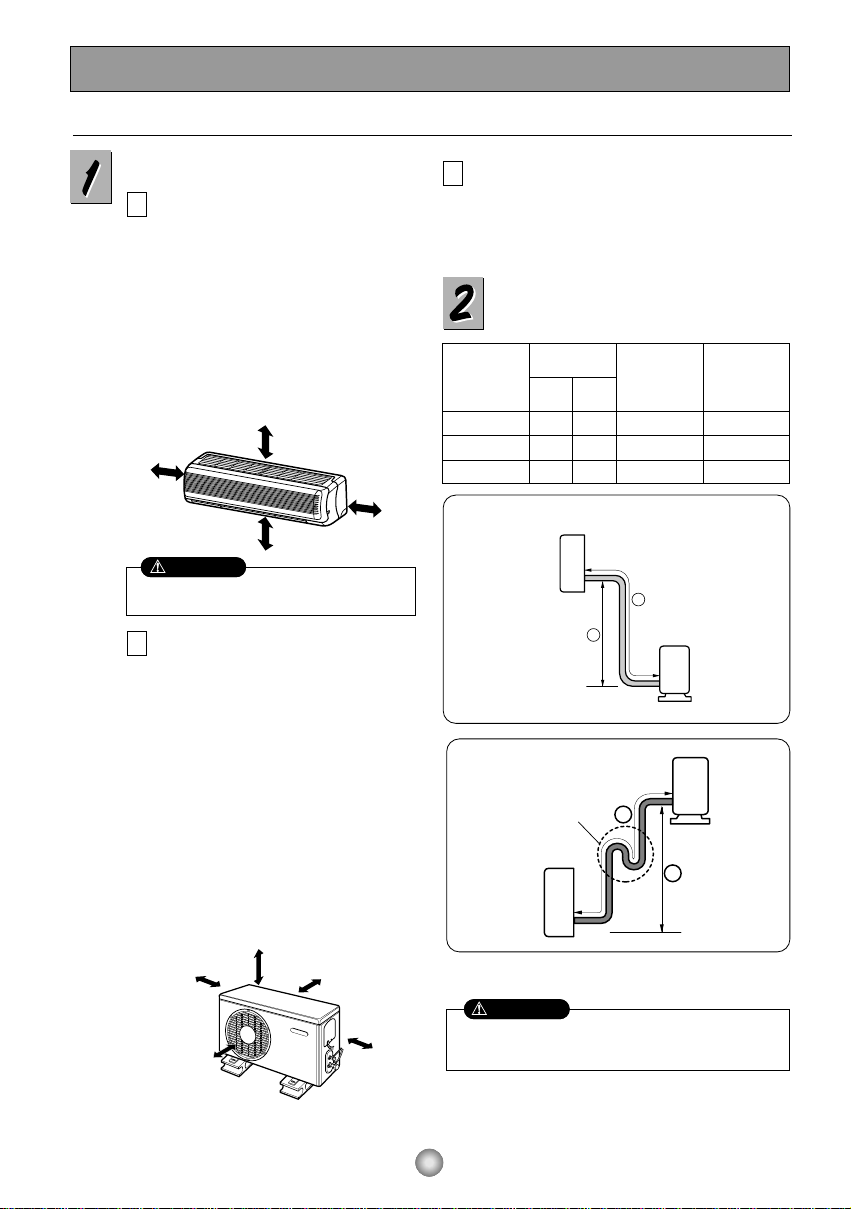
Select the best location
Indoor unit
■
Do not have any heat or steam near the unit.
■
Select a place where there are no
obstacles in front of the unit.
■
Make sure that condensation drainage
can be conveniently routed away.
Do not install near a doorway.
■
Ensure that the space around the left and
right of the unit is more than "A". The unit
should be installed as high on the wall as
possible, allowing a minimum of "B" from
ceiling.
■
Use a stud finder to locate studs to
prevent unnecessary damage to the wall.
Outdoor unit
■
If an awning is built over the unit to
prevent direct sunlight or rain exposure,
make sure that heat radiation from the
condenser is not restricted.
■
Ensure that the space around the back
and sides is more than 10cm. The front of
the unit should have more than 70cm of
space.
■
Do not place animals and plants in the
path of the warm air.
■
Take the air conditioner weight into
account and select a place where noise
and vibration are minimum.
■
Select a place so that the warm air and
noise from the air conditioner do not
disturb neighbors.
Rooftop Installations:
■
If the outdoor unit is installed on a roof structure, be
sure to level the unit. Ensure the roof structure and
anchoring method are adequate for the unit location.
■Consult local codes regarding rooftop mounting.
Piping length and elevation
More than "A"
More than "B"
More than 2.3m
More than "B"
More than 10cm More than 10cm
More
than 60cm
More than 60cm
More than 70cm
If case more than 5m
A
C
B
• Capacity is based on standard length and maximum
allowance length is on the basis of reliability.
• Oil trap should be installed every 5~7 meters.
Outdoor unit
Indoor unit
A
B
A
Oil trap
Outdoor unit
Indoor unit
B
CAUTION
Install the indoor unit on the wall where the height
from the floors more than 2.3 meters.
CAUTION
Pipe Size
MODEL
(Cooling Capa.)
GAS LIQUID
Max.
length
A
Max.
Elevation
B
9K, 12K 1/2" 1/4" 15m(50ft) 8m(26ft)
18K 5/8" 1/4" 15m(50ft) 8m(26ft)
24K 5/8" 3/8" 15m(50ft) 8m(26ft)
ENGLISH
5
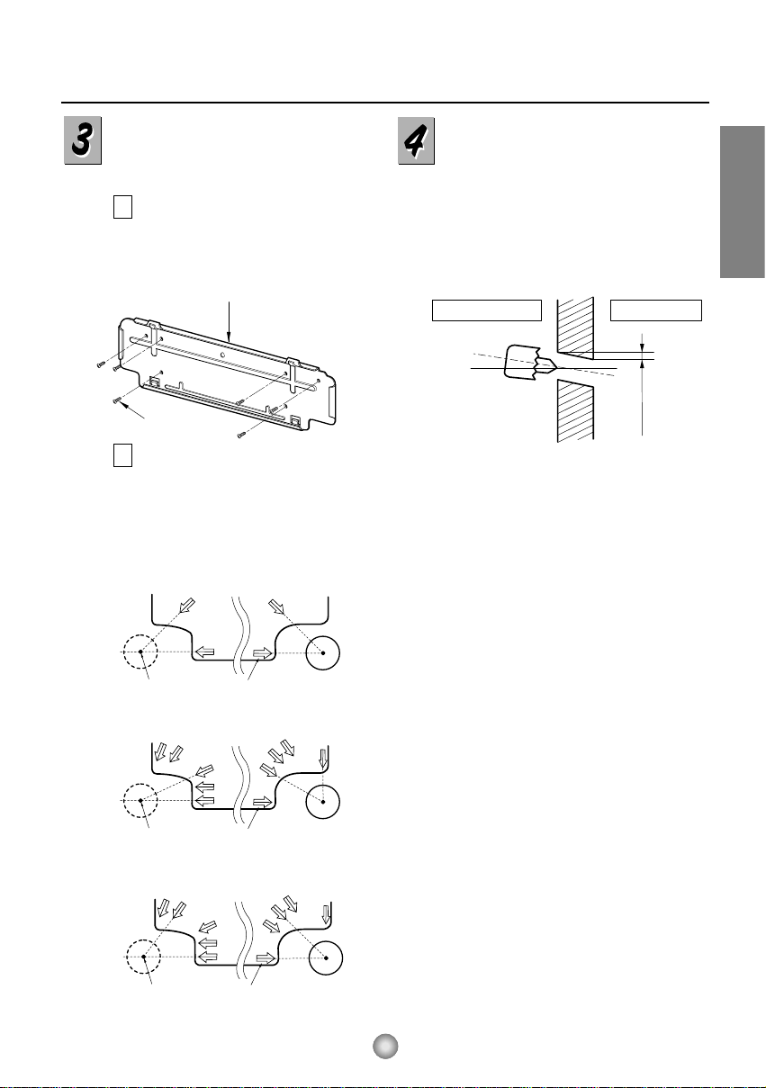
How to fix installation plate
The wall you select should be strong and solid
enough to prevent vibration
Mount the installation plate on the wall with
6 type "A" screws. If mounting the unit on a
concrete wall, use anchor bolts.
■
Mount the installation plate horizontally by
aligning the centerline using a level.
Measure the wall and mark the centerline. It
is also important to use caution concerning
the location of the installation plate-routing of
the wiring to power outlets is through the
walls typically. Drilling the hole through the
wall for piping connections must be done
safely.
5-7mm
(3/16"~5/16")
Indoor
WALL
Outdoor
Installation Plate
Type "A" screw
A,B
A,B,C
C
D
D
A,B,D
C
A
B,D
C
ø70m
m
(2.76")
Left rear piping Right rear piping
Hole Center Installation plate
ø70m
m
(2.76")
Left rear piping Right rear piping
Hole Center Installation plate
A,B
A,B,C
C
D
D
A,B,D
C
A
B,D
C
ø85m
m
(3.35")
Left rear piping Right rear piping
Hole Center Installation plate
9K Btu
12K Btu
18K, 24K Btu
A
B
■
Drill the piping hole with a ø70mm hole core
drill. Drill the piping hole at either the right or
the left with the hole slightly slanted to the
outdoor side.
Drill a hole in the wall
6
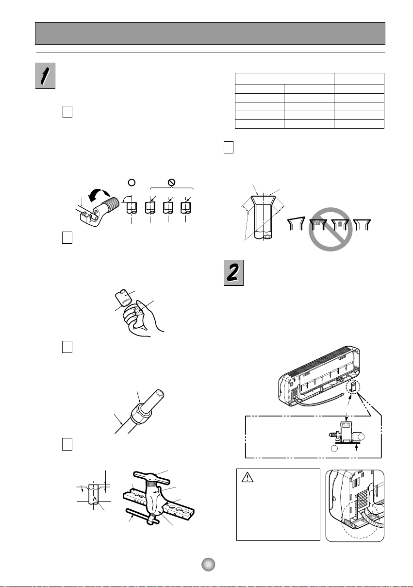
Connection of piping -- Indoor
■
Preparing the indoor unit's piping and drain
hose for installation through the wall.
■
Remove the plastic tubing retainer(see
illustration below) and pull the tubing and
drain hose away from chassis.
■ Replace the plastic tubing holder in the
original position.(Optional)
FLARING WORK AND CONNECTION OF PIPING
Flaring work
Main cause for refrigerant leakage is due to defect
in the flaring work. Carry out correct flaring work
using the following procedure.
Cut the pipes and the cable.
■ Use the piping kit accessory or pipes
purchased locally.
■ Measure the distance between the indoor and
the outdoor unit.
■ Cut the pipes a little longer than the measured
distance.
■ Cut the cable 1.5m longer than the pipe length.
Burr removal
■
Completely remove all burrs from the cut
cross section of pipe/tube.
■
Put the end of the copper tube/pipe in a
downward direction as you remove burrs in
order to avoid dropping burrs into the tubing.
A
B
Putting nut on
■
Remove flare nuts attached to indoor and
outdoor unit, then put them on pipe/tube
having completed burr removal.
(not possible to put them on after flaring work)
C
■
Carry out flaring work using flaring tool as shown below.
Check
■
Compare the flared work with figure below.
■
If flare is noted to be defective, cut off the flared
section and re-flare it.
E
mm inch mm
Ø6.35 1/4 0~0.5
Ø9.52 3/8 0~0.5
Ø12.7 1/2 0~0.5
Ø15.88 5/8 0~1.0
Outside diameter A
Flare nut
Copper tube
To remove the holder,
press the bottom of
chassis near the holder
upward and pull the tab
out of its hole.
Tubing holder
Pull
Press
2
1
Inclined
Inside is shiny without scratches
Smooth all round
Even length
all round
Surface
damaged
Cracked Uneven
thickness
= Improper flaring =
CAUTION
When install, make sure
that the remaining parts
must be removed clearly
so as not to damage the
piping and drain hose,
especially power cord
and connecting cable.
Flaring work
■
Firmly hold copper pipe in a die in the
dimension shown in the table above.
D
Copper
pipe
Point down
Slanted Uneven Rough
90°
Pipe
Reamer
Bar
"A"
Copper pipe
Clamp handle
Bar
Handle
Yoke
Cone
Red arrow mark
 Loading...