

Lg Asnc091f2g0, Asnc121f2g0, Asnh091f2g1, Asnh121f2g1, Asnh121f2g0 Owner's Manual
...
Universal Air Conditioner
SVC MANUAL(Exploded View)
MODEL : LAN126HNP(ASNH121F2G1) LAU126HNP(ASUH121FUG1)
LAN096HNP(ASNH091F2G1) LAU096HNP(ASUH091FUG1)
LAN091CNP (ASNC091F2G0) LAU091CNP (ASUC091FUG0)
LAN121CNP (ASNC121F2G0) LAU121CNP (ASUC121FUG0)
LAN091HNP (ASNH091F2G0) LAU091HNP (ASUH091FUG0)
LAN121HNP (ASNH121F2G0) LAU121HNP (ASUH121FUG0)
LA090CPI (ASNC091F2G0) LA090CPO (ASUC091FUG0)
LA120CPI (ASNC091F2G0) LA120CPO (ASUC091FUG0)
LA090HPI (ASNH091F2G0) LA090HPO (ASUH091FUG0)
LA120HPI (ASNH121F2G0) LA120HPO (ASUH121FUG0)
CAUTION
Before Servicing the unit, read the safety precautions in General SVC manual.
Only for authorized service personnel.
Internal Use Only
http://biz.lgservice.com

- 2 -
Copyright ©2010 LG Electronics. Inc. All right reserved.
Only for training and service purposes
LGE Internal Use Only
Air Conditioner Service Manual
TABLE OF CONTENTS
Safety Precautions ...........................................................................................................................................................3
Dimensions .......................................................................................................................................................................9
Symbols Used in this Manual .....................................................................................................................................9
Indoor Unit ..................................................................................................................................................................9
Outdoor Unit .............................................................................................................................................................10
Product Specifications ..................................................................................................................................................11
Installation ......................................................................................................................................................................13
Installation Parts .......................................................................................................................................................13
Installation Tools.......................................................................................................................................................13
Installtion Map...........................................................................................................................................................14
Confirm the Refrigerant ............................................................................................................................................15
Select the best Locations..........................................................................................................................................16
Piping Length and Elevation .....................................................................................................................................17
Preparing Work for Installation .................................................................................................................................18
Fixing Indoor Unit......................................................................................................................................................19
Flaring work and connection of piping ........................................................................................................................20
Flaring work ..............................................................................................................................................................20
Connection of piping-Indoor......................................................................................................................................21
Connection of the drain hose....................................................................................................................................22
Connection of piping-Outdoor...................................................................................................................................24
Connecting the cable between indoor unit and outdoor unit ....................................................................................25
Connect the cable to the Indoor unit.........................................................................................................................25
Connection method of the connecting cable(Example) ............................................................................................26
Checking the drainage and forming the pipings.........................................................................................................27
Checking the drainage..............................................................................................................................................28
Forming the piping ....................................................................................................................................................29
AIR PURGING .................................................................................................................................................................30
Air purging ................................................................................................................................................................30
Charging ...................................................................................................................................................................32
Panel front assembly ................................................................................................................................................33
Test running..............................................................................................................................................................34
How to replace picture & photograph ..........................................................................................................................36
Operation ........................................................................................................................................................................37
Functions ..................................................................................................................................................................37
The function of main control .....................................................................................................................................38
Display Function ......................................................................................................................................................44
Self-diagnosis Function ............................................................................................................................................44
Remote Control Operations ......................................................................................................................................45
Disassembly ...................................................................................................................................................................46
Indoor Unit ................................................................................................................................................................46
Schematic Diagram ........................................................................................................................................................48
Heat Pump/Cooling Only Series(Indoor Unit) ...........................................................................................................48
Heat Pump Series (Outdoor Unit).............................................................................................................................49
INDOOR UNIT P.W.B. ASSEMBLY .........................................................................................................................50
OUTDOOR UNIT P.W.B. ASSEMBLY .....................................................................................................................51
DISPLAY P.W.B. ASM..............................................................................................................................................52
Wiring Diagram .........................................................................................................................................................53
Troubleshooting Guide..................................................................................................................................................55
Refrigeration Cycle Diagram.....................................................................................................................................55
Pipe length and the elevation ...................................................................................................................................56
3-way Valve ..............................................................................................................................................................57
Cycle Parts ...............................................................................................................................................................63
Electronic Parts.........................................................................................................................................................64
Exploded View ................................................................................................................................................................73
- 3 -
Copyright ©2010 LG Electronics. Inc. All right reserved.
Only for training and service purposes
LGE Internal Use Only
Safety Precautions
Safety Precautions
To prevent injury to the user or other people and property damage, the following instructions must
be followed.
■ Incorrect operation due to ignoring instruction will cause harm or damage. The seriousness is
classified by the following indications.
■ Meanings of symbols used in this manual are as shown below.
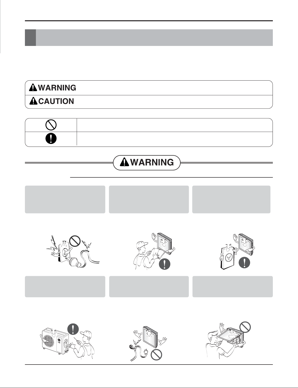
This symbol indicates the possibility of death or serious injury.
This symbol indicates the possibility of injury or damage to properties only.
Be sure not to do.
Be sure to follow the instruction.
■ Installation
Do not use damaged power
cords, plugs, or a loose socket.
• There is risk of fire or electric
shock.
For electrical work, contact the
dealer, seller, a qualified
electrician, or an Authorized
Service Center.
• There is risk of fire or electric
shock.
Always use the power plug and
socket with the ground terminal.
• There is risk of electric shock.
Install the panel and the cover of
control box securely.
• There is risk of fire or electric
shock.
Do not modify or extend the
power cord.
• There is risk of fire or electric
shock.
Do not install, remove, or reinstall the unit by yourself
(customer).
• There is risk of fire, electric shock,
explosion, or injury.
- 4 -
Copyright ©2010 LG Electronics. Inc. All right reserved.
Only for training and service purposes
LGE Internal Use Only
Safety Precautions
■ Operation
Be cautious when unpacking and
installing the product.
• Sharp edges could cause injury. Be
especially careful of the case
edges and the fins on the
condenser and evaporator.
For installation, always contact
the dealer or an Authorized
Service Center.
• There is risk of fire, electric shock,
explosion, or injury.
Do not install the product on a
defective installation stand.
• It may cause injury, accident, or
damage to the product.
Be sure the installation area
does not deteriorate with age.
• If the base collapses, the air
conditioner could fall with it,
causing property damage, product
failure, and personal injury.
Do not let the air conditioner run
for a long time when the humidity
is very high and a door or a
window is left open.
• Moisture may condense and wet or
damage furnishings.
Take care to ensure that power
cords could not be pulled out or
damaged during operation.
• There is risk of fire or electrical
shock.
Do not place anything on the
power cord.
• There is risk of fire or electric
shock.
Do not turn the air-conditioner
ON or OFF by plugging or
unplugging the power plug.
• There is risk of fire or electrical
shock.
- 5 -
Copyright ©2010 LG Electronics. Inc. All right reserved.
Only for training and service purposes
LGE Internal Use Only
Safety Precautions
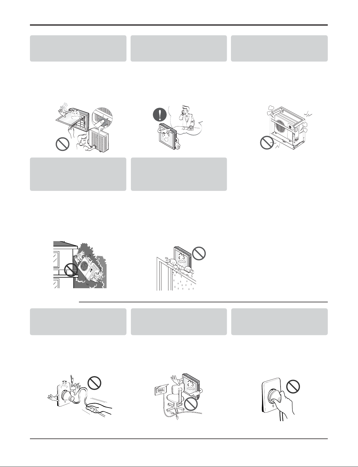
Use a dedicated outlet for this
appliance.
• There is risk of fire or electrical
shock.
Grasp the plug to remove the
cord from the outlet. Do not
touch it with wet hands.
• There is risk of fire or electrical
shock.
Do not place a heater or other
appliances near the power cable.
• There is risk of fire and electric
shock.
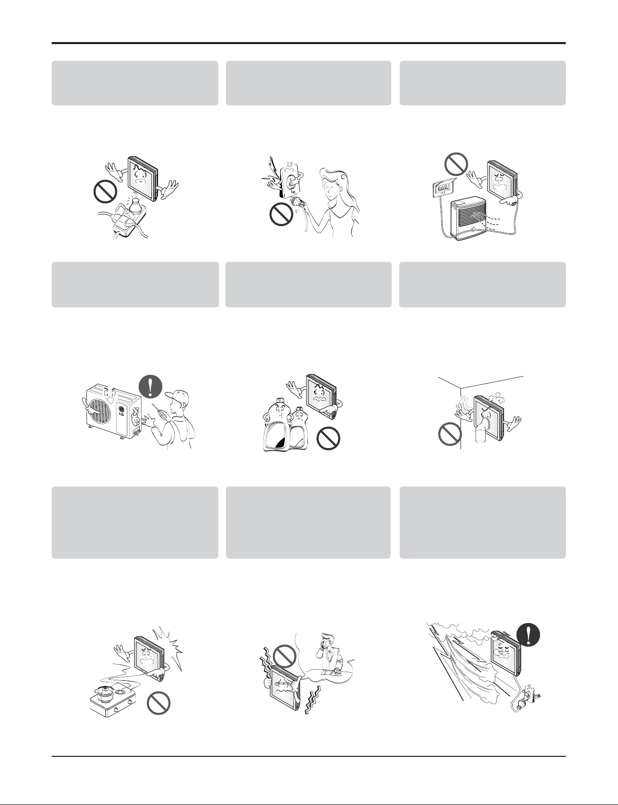
Do not allow water to run into
electric parts.
• It may cause There is risk of fire,
failure of the product, or electric
shock.
Do not store or use flammable
gas or combustibles near the air
conditioner.
• There is risk of fire or failure of
product.
Do not use the product in a
tightly closed space for a long
time.
• Oxygen deficiency could occur.
When flammable gas leaks, turn
off the gas and open a window for
ventilation before turn the product
on. DO NOT use the telephone or
turn switches on or off.
• There is risk of explosion or fire.
Unplug the unit if strange
sounds, odors, or smoke comes
from it.
• There is risk of electrical shock or
fire
Stop operation and close the
window in storm or hurricane. If
possible, remove the air
conditioner from the window
before the hurricane arrives.
• There is risk of property damage,
failure of product, or electric shock.
Thinner
Wax
- 6 -
Copyright ©2010 LG Electronics. Inc. All right reserved.
Only for training and service purposes
LGE Internal Use Only
Safety Precautions
■ Installation
Do not open the inlet grill of the
product during operation. (Do
not touch the electrostatic filter,
if the unit is so equipped.)
• There is risk of physical injury,
electric shock, or product failure.
When the product is soaked
(flooded or submerged), contact
an Authorized Service Center.
• There is risk of fire or eletric
shock.
Ventilate the product from time
to time when operating it
together with a stove, etc.
• There is risk of fire or electrical
shock.
Unplug the appliance before
performing cleaning or
maintenance.
• There is risk of electrical shock.
When the product is not be used
for a long time, disconnect the
power supply plug or turn off the
breaker.
• There is risk of product damage or
failure, or unintended operation.
Take care to ensure that nobody
could step on or fall onto the
outdoor unit.
• This could result in personal injury
and product damage.
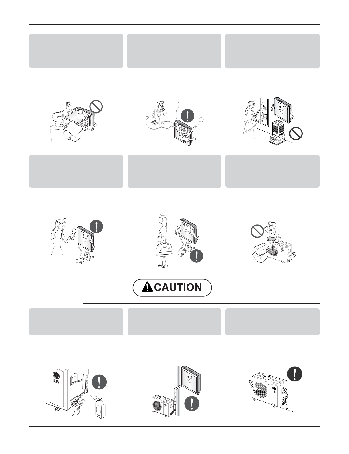
Always check for gas
(refrigerant) leakage after
installation or repair of product.
• Low refrigerant levels may cause
failure of product.
Install the drain hose to ensure
that water is drained away
properly.
• A bad connection may cause water
leakage.
Keep level even when installing
the product.
• To avoid vibration or water leakage.
90˚
- 7 -
Copyright ©2010 LG Electronics. Inc. All right reserved.
Only for training and service purposes
LGE Internal Use Only
Safety Precautions
■ Operation
Do not install the product where
the noise or hot air from the
outdoor unit could damage the
neighborhoods.
• It may cause a problem for your
neighbors.
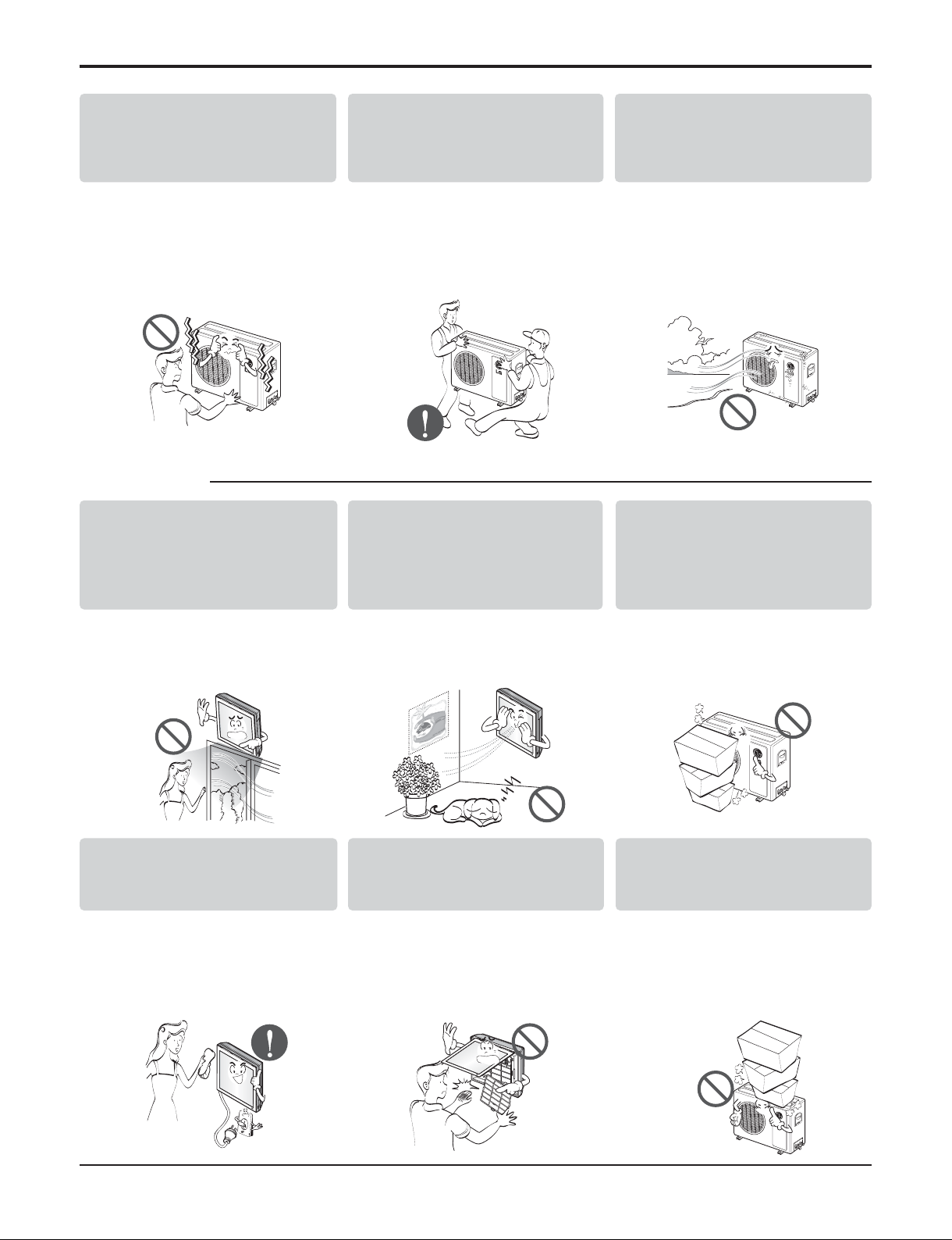
Use two or more people to lift
and transport the air conditioner.
• Avoid personal injury.
Do not install the product where
it will be exposed to sea wind
(salt spray) directly.
• It may cause corrosion on the
product. Corrosion, particularly on
the condenser and evaporator fins,
could cause product malfunction or
inefficient operation.
Do not direct airflow at room
occupants. (Don't sit in the
draft.)
• This could damage your health.
Do not use the product for special
purposes, such as preserving
foods, works of art, etc. It is a
consumer air conditioner, not a
precision refrigeration system.
• There is risk of damage or loss of
property.
Do not block the inlet or outlet of
air flow.
• It may cause product failure.
Use a soft cloth to clean. Do not
use harsh detergents, solvents,
etc.
• There is risk of fire, electric shock,
or damage to the plastic parts of
the product.
Do not touch the metal parts of
the product when removing the
air filter. They are very sharp!
• There is risk of personal injury.
Do not step on or put anyting on
the product. (outdoor units)
• There is risk of personal injury and
failure of product.
- 8 -
Copyright ©2010 LG Electronics. Inc. All right reserved.
Only for training and service purposes
LGE Internal Use Only
Always insert the filter securely.
Clean the filter every two weeks
or more often if necessary.
• A dirty filter reduces the efficiency
of the air conditioner and could
cause product malfunction or
damage.
Do not insert hands or other
objects through the air inlet or
outlet while the air conditioner is
plugged in.
• There are sharp and moving parts
that could cause personal injury.
Do not drink the water drained
from the unit.
• It is not sanitary and could cause
serious health issues.
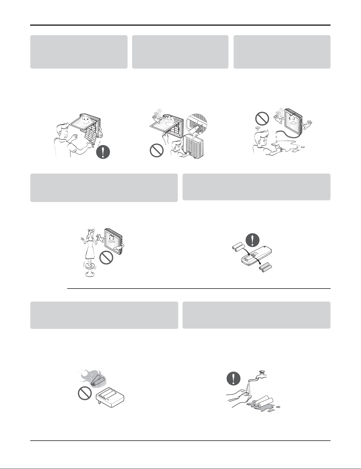
Use a firm stool or ladder when cleaning or
maintaining the air conditioner.
• Be careful and avoid personal injury.
Replace the all batteries in the remote control with
new ones of the same type. Do not mix old and new
batteries or different types of batteries.
• There is risk of fire or explosion
Do not recharge or disassemble the batteries. Do
not dispose of batteries in a fire.
• They may burn or explode.
If the liquid from the batteries gets onto your skin
or clothes, wash it well with clean water. Do not
use the remote if the batteries have leaked.
• The chemicals in batteries could cause burns or other
health hazards.
■ Disuse
Safety Precautions
- 9 -
Copyright ©2010 LG Electronics. Inc. All right reserved.
Only for training and service purposes
LGE Internal Use Only
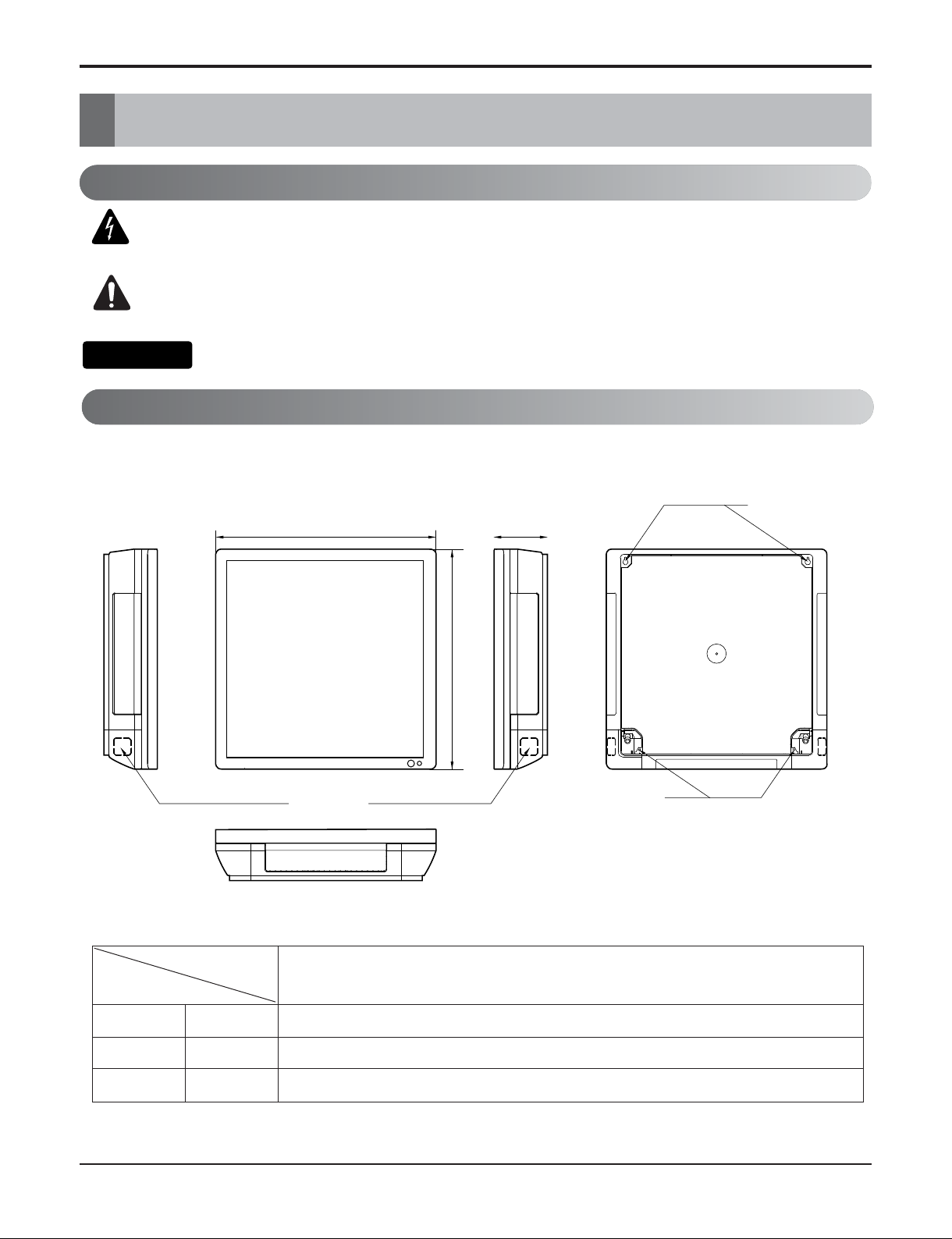
Dimensions
Dimensions
Indoor Unit
This symbol alerts you to the risk of electric shock.
This symbol alerts you to hazards that could cause harm to the
air conditioner.
This symbol indicates special notes.
Symbols Used in this Manual
Pipe Hole
Fix Hole
Hanger Hole
H
W
D
W mm(inch) 600(23.6)
H mm(inch) 600(23.6)
D mm(inch) 146(5.7)
Model
Dimension
INDOOR UNIT
NOTICE
- 10 -
Copyright ©2010 LG Electronics. Inc. All right reserved.
Only for training and service purposes
LGE Internal Use Only
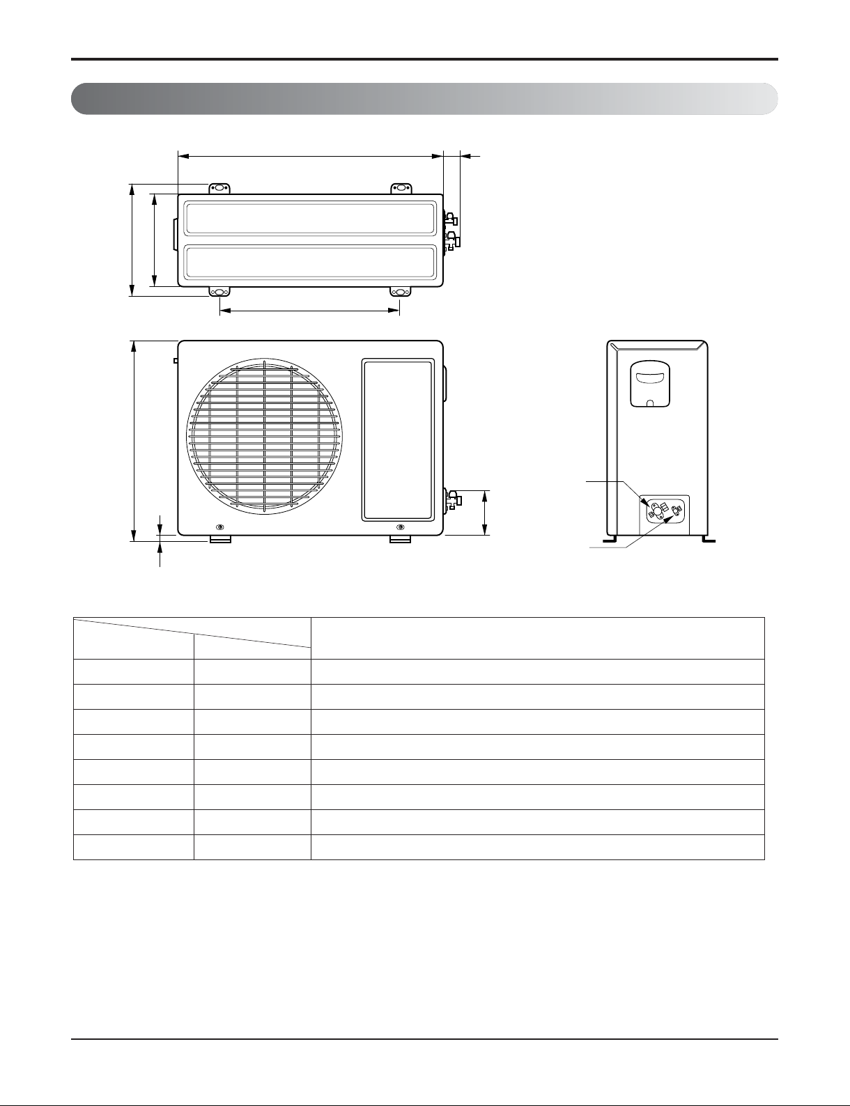
Dimensions
Outdoor Unit
W
L2
L3
L1
D
H
L4
L5
Gas side
(3-way valve)
Liquid side
(2-way valve)
MODEL
9k, 12k Models
DIM unit
W mm 770(30.3)
H mm 540(21.3)
D mm 245(9.6)
L1 mm 285(11.2)
L2 mm 64(2.5)
L3 mm 518(20.4)
L4 mm 10(0.4)
L5 mm 100(3.9)
- 11 -
Copyright ©2010 LG Electronics. Inc. All right reserved.
Only for training and service purposes
LGE Internal Use Only
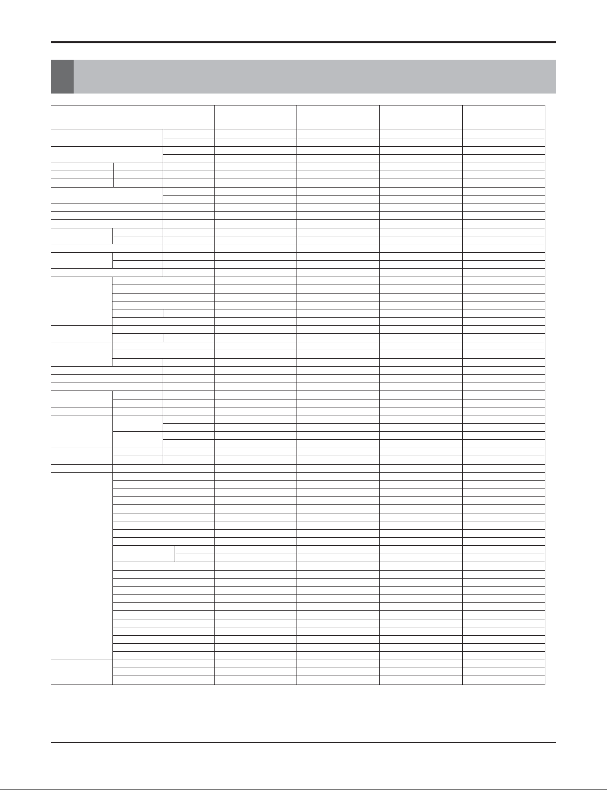
Product Specifications
Product Specifications
Models
Cooling Capacity kW
(Min~Rating~Max) Btu/h
Heating Capacity kW
(Min~Rating~Max) Btu/h
Power Input Cooling/Heating W
Running Current Cooling/Heating A
Starting Current Cooling/Heating A
EER
W/W
Btu/h.W
COP W/W
Power Supply Ø / V / Hz
Power Factor %
Air Flow Rate
Indoor,Max
m3/min(cfm)
Outdoor,Max
m3/min(cfm)
Moisture Removal l/h
Sound Level
Indoor,H/M/L dB(A)+3
Outdoor,Max dB(A)+3
Refrigerant & Charge(at 7.5m) g(oz)
Compressor
Type
Model
Motor Type
Oil Type
Oil Charge cc
O.L.P Name
Fan(Indoor)
Type
Motor Output W
Fan(outdoor)
Type
Motor Type
Motor Output W
Circuit Breaker* A
Power Supply Cable No.*mm
2
Power and Transmission Cable
No.*mm2+No.mm
2
Piping Liquid Side mm(in)
Connections Gas Side mm(in)
Drain Hose O.D , I.D mm(in)
Indoor(W*H*D)
mm
Dimension
inch
Outdoor(W*H*D)
mm
inch
Indoor kg(lbs)
Net Weight
Outdoor kg(lbs)
Tool Code(Chassis) Indoor + Outdoor
Temperature Control
Functions Plasma Filter
Prefilter(washable/anti-fungus)
Auto Clean
CHAOS Wind(Auto Wind)
Steps, Fan/Cool/Heat
Airflow Direction Control(up&down)
Airflow Direction Control(left&right)
Remocon Type
Setting Temperature Cooling
Range Heating
Auto Operation (Micom Control)
Auto Changeover (Micom Control)
Self Diagnosis
Timer
Sleep Operation
Soft Dry Operation
Restart Delay(minute)
Deice Control(Defrost)
Hot Start
Jet Cool
Low Ambient Operation
Special Function
Network Functions
Dry Contact
Network Solution(LGAP)
PI485
2.87 3.37 2.87 3.37
9,800 11,500 9,800 11,500
- - 2.87 3.37
- - 9,800 11,500
980 1,100 980/980 1,100/1,100
9.4 10 9.4/9.4 10/10
57.0 57.0 57.0/57.0 57.0/57.0
2.93 3.06 2.93 3.06
10.0 10.5 10.0 10.5
- - 2.93 3.06
1/115/60 1/115/60 1/115/60 1/115/60
90.7 95.7 90.7 95.7
9.3(330) 9.3(330) 9.3(330) 9.3(330)
25(883) 25(883) 25(883) 25(883)
1.4 1.4 1.4 1.4
41/35/29 41/35/29 41/35/29 41/35/29
48 48 48 48
R410A, 900(31.8) R410A, 900(31.8) R410A, 900(31.8) R410A, 900(31.8)
Rotary Rotary Rotary Rotary
GK113CAA GK113CAA GK113CAA GK113CAA
PSC PSC PSC PSC
FVC68D(PVE) FVC68D(PVE) FVC68D(PVE) FVC68D(PVE)
330 330 330 330
MRA12053-12027 MRA12053-12027 MRA12053-12027 MRA12053-12027
Turbo Fan Turbo Fan Turbo Fan Turbo Fan
24 24 24 24
Propeller Propeller Propeller Propeller
AC Induction AC Induction AC Induction AC Induction
27 27 27 27
20 20 20 20
3*2.5 3*2.5 3*2.5 3*2.5
4*0.75 4*0.75 4*0.75 4*0.75
6.35(1/4) 6.35(1/4) 6.35(1/4) 6.35(1/4)
12.7(1/2) 12.7(1/2) 12.7(1/2) 12.7(1/2)
21.5,16(0.85,0.63) 21.5,16(0.85,0.63) 21.5,16(0.85,0.63) 21.5,16(0.85,0.63)
600*600*146 600*600*146 600*600*146 600*600*146
23.62*23.62*5.75 23.62*23.62*5.75 23.62*23.62*5.75 23.62*23.62*5.75
770*540*245 770*540*245 770*540*245 770*540*245
30.31*21.26*9.65 30.31*21.26*9.65 30.31*21.26*9.65 30.31*21.26*9.65
15(33.1) 15(33.1) 15(33.1) 15(33.1)
32(70.5) 32(70.5) 32(70.5) 32(70.5)
SF + UL SF + UL SF + UL SF + UL
Thermistor Thermistor Thermistor Thermistor
OOOO
OOOO
OOOO
OOOO
3/4 3/4 3/4/3 3/4/3
Auto Auto Auto Auto
Auto Auto Auto Auto
Wireless LCD Wireless LCD Wireless LCD Wireless LCD
18 ~ 30 18 ~ 30 18 ~ 30 18 ~ 30
- - 16 ~ 30 16 ~ 30
OOOO
OOOO
OOOO
24h, On/Off 24h, On/Off 24h, On/Off 24h, On/Off
OOOO
OOOO
3333
--
OO
--
OO
OOOO
----
----
----
----
----
Note:
O : Applied, - : No relation
* For circuit breaker rating, please conform to local standards wherever necessary.
※ Some of functions are slightly different depending upon models.
※
The specification may be subject to change without notic for purpose of improvement.
AS-C091F2G0(LA091CNP)
AS-C091F2G0(LA090CP)
AS-C121F2G0(LA121CNP)
AS-C121F2G0(LA120CP)
AS-H091F2G0(LA091HNP)
AS-H091F2G0(LA090HP)
AS-H121F2G0(LA121HNP)
AS-H121F2G0(LA120HP)
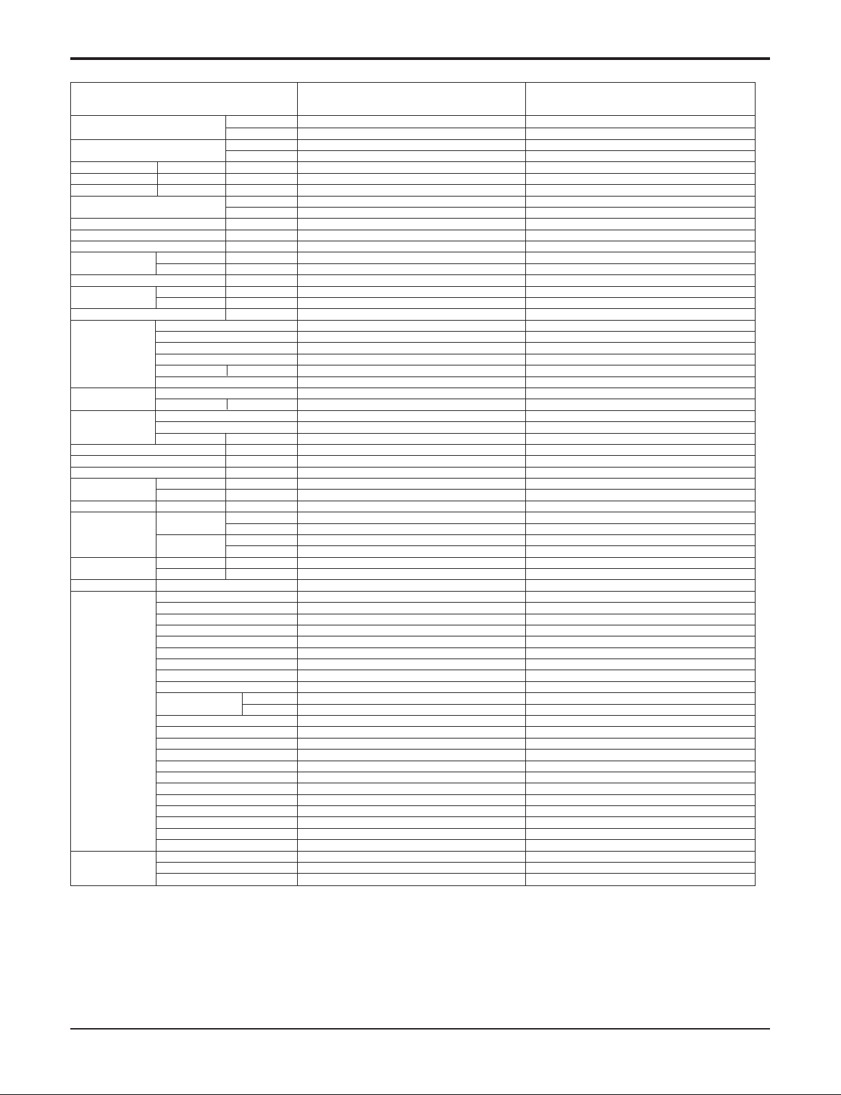
Product Specifications
- 12 -
Copyright ©2010 LG Electronics. Inc. All right reserved.
Only for training and service purposes
LGE Internal Use Only
Models
Cooling Capacity kW
(Min~Rating~Max) Btu/h
Heating Capacity kW
(Min~Rating~Max) Btu/h
Power Input Cooling/Heating W
Running Current Cooling/Heating A
Starting Current Cooling/Heating A
EER
W/W
Btu/h.W
COP W/W
Power Supply Ø / V / Hz
Power Factor %
Air Flow Rate
Indoor,Max
m3/min(cfm)
Outdoor,Max
m3/min(cfm)
Moisture Removal l/h
Sound Level
Indoor,H/M/L dB(A)+3
Outdoor,Max dB(A)+3
Refrigerant & Charge(at 7.5m) g(oz)
Compressor
Type
Model
Motor Type
Oil Type
Oil Charge cc
O.L.P Name
Fan(Indoor)
Type
Motor Output W
Fan(outdoor)
Type
Motor Type
Motor Output W
Circuit Breaker* A
Power Supply Cable No.*mm
2
Power and Transmission Cable
No.*mm2+No.mm
2
Piping Liquid Side mm(in)
Connections Gas Side mm(in)
Drain Hose O.D , I.D mm(in)
Indoor(W*H*D)
mm
Dimension
inch
Outdoor(W*H*D)
mm
inch
Indoor kg(lbs)
Net Weight
Outdoor kg(lbs)
Tool Code(Chassis) Indoor + Outdoor
Temperature Control
Functions Plasma Filter
Prefilter(washable/anti-fungus)
Auto Clean
CHAOS Wind(Auto Wind)
Steps, Fan/Cool/Heat
Airflow Direction Control(up&down)
Airflow Direction Control(left&right)
Remocon Type
Setting Temperature Cooling
Range Heating
Auto Operation (Micom Control)
Auto Changeover (Micom Control)
Self Diagnosis
Timer
Sleep Operation
Soft Dry Operation
Restart Delay(minute)
Deice Control(Defrost)
Hot Start
Jet Cool
Low Ambient Operation
Special Function
Network Functions
Dry Contact
Network Solution(LGAP)
PI485
2.9 3.37
9,900 11,500
2.9 3.22
9,900 11,000
1,100/1,070 1,150/1,100
9.4/9.4 10-10
57.0/57.0 57.0/57.0
2.63 2.93
910
2.71 2.93
1/115/60 1/115/60
90.7 95.7
9.3(330) 9.3(330)
25(883) 25(883)
1.4 1.4
43/35/29 43/35/29
48 48
R410A, 900(31.8) R410A, 900(31.8)
Rotary Rotary
GK113CAA GK113CAA
PSC PSC
FVC68D(PVE) FVC68D(PVE)
330 330
MRA12053-12027 MRA12053-12027
Turbo Fan Turbo Fan
24 24
Propeller Propeller
AC Induction AC Induction
27 27
20 20
3*2.5 3*2.5
4*0.75 4*0.75
6.35(1/4) 6.35(1/4)
12.7(1/2) 12.7(1/2)
21.5,16(0.85,0.63) 21.5,16(0.85,0.63)
600*600*146 600*600*146
23.62*23.62*5.75 23.62*23.62*5.75
770*540*245 770*540*245
30.31*21.26*9.65 30.31*21.26*9.65
15(33.1) 15(33.1)
32(70.5) 32(70.5)
SF + UL SF + UL
Thermistor Thermistor
OO
OO
OO
OO
2003-04-03 2003-04-03
Auto Auto
Auto Auto
Wireless LCD Wireless LCD
18 ~ 30 18 ~ 30
16 ~ 30 16 ~ 30
OO
OO
OO
24h, On/Off 24h, On/Off
OO
OO
33
OO
OO
OO
--
--
--
--
--
Note:
O : Applied, - : No relation
* For circuit breaker rating, please conform to local standards wherever necessary.
※ Some of functions are slightly different depending upon models.
※
The specification may be subject to change without notic for purpose of improvement.
AS-H091F2G1
(LA096HNP)
AS-H121F2G1
(LA126HNP)
- 13 -
Copyright ©2010 LG Electronics. Inc. All right reserved.
Only for training and service purposes
LGE Internal Use Only
Installation
Installation
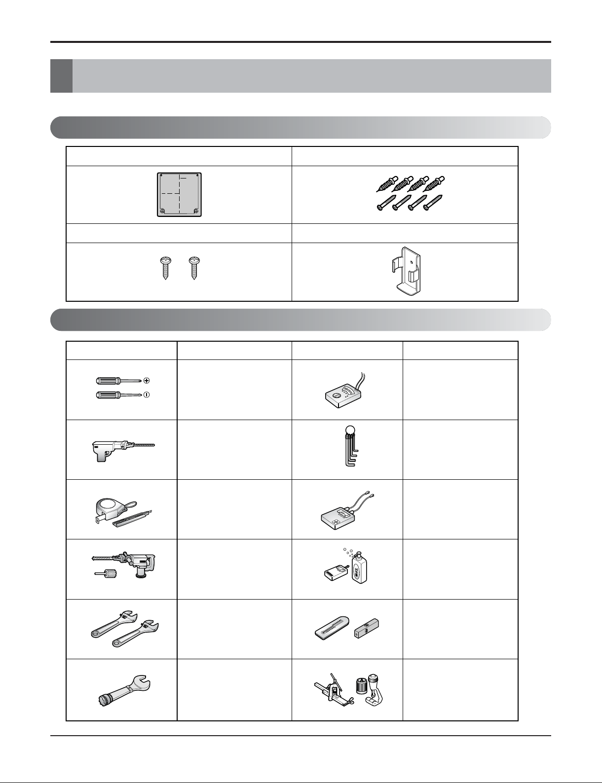
Installation Parts
Installation Tools
Read carefully, and then follow step by step.
Type "A" screw and plastic anchor
Type "B" screw
Remote control holder
Installation guide map
Figure FigureName
Screw driver
Electric drill
Measuring tape, Knife
Hole core drill
Spanner
Torque wrench
Ohmmeter
Hexagonal wrench
Ammeter
Leak detector
Thermometer,
Horizontal meter
Flaring tool set
Name
- 14 -
Copyright ©2010 LG Electronics. Inc. All right reserved.
Only for training and service purposes
LGE Internal Use Only
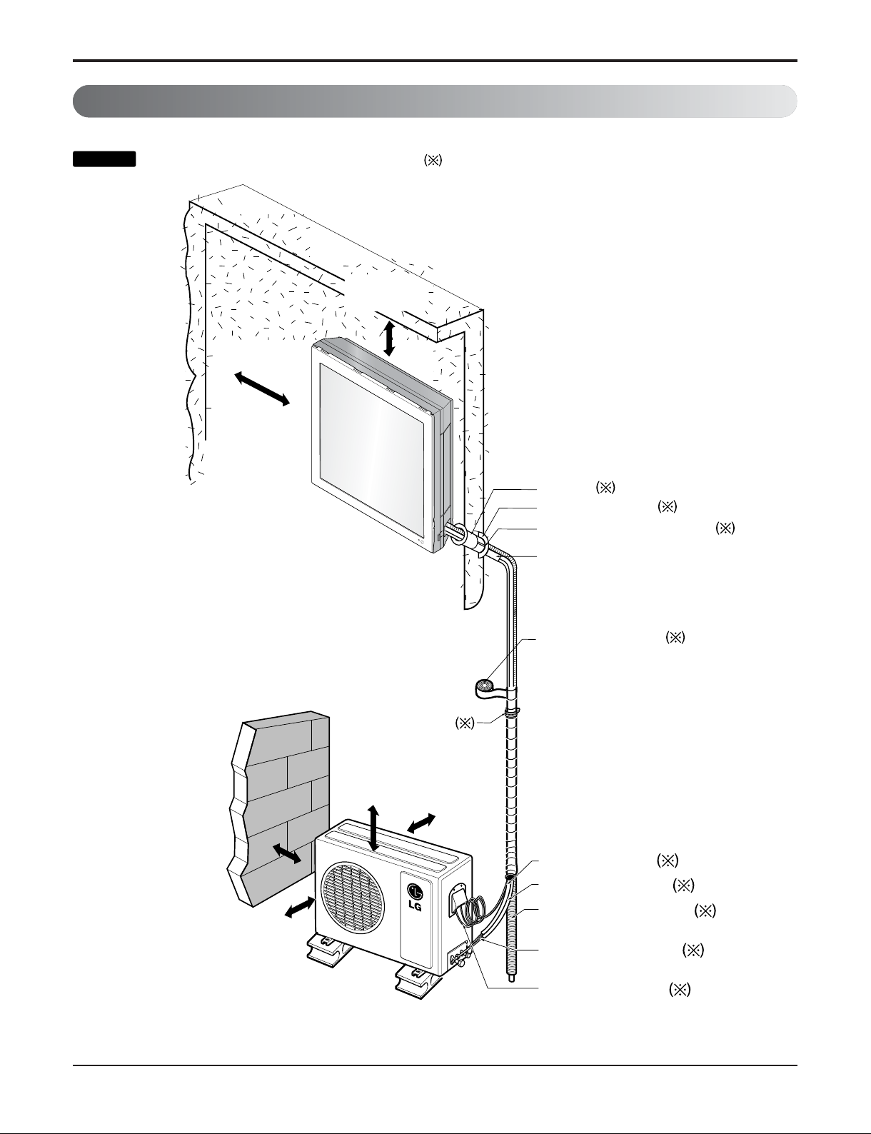
Installation Map
Installation parts you should purchase.
NOTICE
(Left and right
are identical)
More than
28"(70cm)
More than
23.6"(60cm)
Sleeve
Bushing-Sleeve
Putty(Gum Type Sealer)
Vinyl tape (Wide)
• To carry out the drainage
test, remove the air filter
and pour water into the heat
exchanger.
• Apply after carrying out a
drainage test.
Saddle
More than
19.6"(50cm)
Gas side piping (Optional part)
Liquid side piping (Optional part)
Additional drain pipe
Vinyl tape (Narrow)
Connecting cable
(Optional part)
Bend the pipe as close as possible
on the wall but be careful so that it
may not break.
More than More than
11.8"(30cm )11.8"(30cm )
More than
11.8"(30cm )
More than More than
11.8"(30cm) 11.8"(30cm)
More than
11.8"(30cm)
More than More than
3.9"(10cm) 3.9"(10cm)
More than
7.9"(20cm)
Installation
- 15 -
Copyright ©2010 LG Electronics. Inc. All right reserved.
Only for training and service purposes
LGE Internal Use Only
1. Check the quality label on the indoor and outdoor unit.
2. Make certain that the refrigerant is R-410A.
THIS PRODUCT CONTAINS R-410A REFRIGERANT
1) Different compressor oil
- R-410A(Polyol ester) / R-22(Mineral).
- Do not mix the existing mineral oil.
- Do not apply used pipe, tools and gauges covered with the existing mineral oil.
2) Absorption of moisture
-Compressorʼs oil has the high absorption rate of moisture.
3) Composition
- R-410A(R32:R125=50:50wt%).
NOTE: Never mix with other refrigerants
4) High pressure.
- 1.6 times higher than R-22.
- High Pressure refrigerant may cause personal injury.
Do not handle the pipe by yourself (customer) High-pressure refrigerant may cause personal injury.
- manifold gauge ,charging and any piping tools must be dedicated to R-410A systems.
Confirm The Refrigerant
Boiling Pt.(
°C) Vapor pressure(25°C)(kg f/cnf) Vapor density(25°C)(kg/m2)
R-410A -51.4 15.9 64
R-22 -40.8 9.6 44.4
Installation
NOTICE
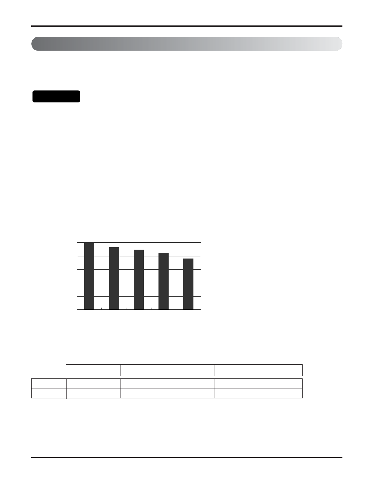
Example : Split type 12,000 Btu/h
Capacity
[%]
120
100
80
100
93
89
84
76
60
40
20
0
R-410A
R-22
100%
70% 50% 30%
0%
100%70%50%30%0%
- 16 -
Copyright ©2010 LG Electronics. Inc. All right reserved.
Only for training and service purposes
LGE Internal Use Only
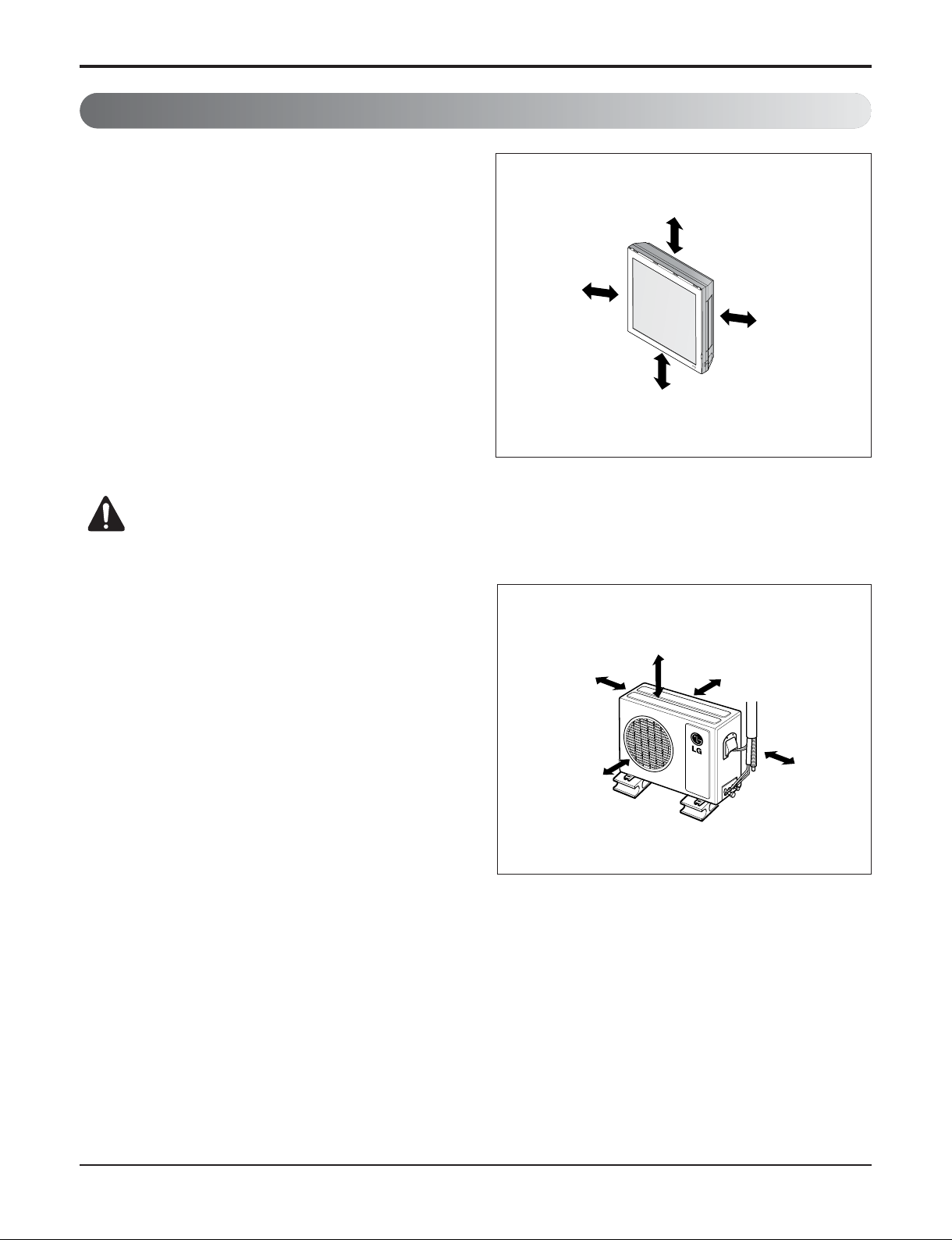
Indoor unit
1. Do not have any heat or steam near the unit.
2. Select a place where there are no obstacles in front
of the unit.
3. Make sure that condensation drainage can be
conveniently routed away.
4. Do not install near a doorway.
5. Ensure that the interval between a wall and the left
(or right) of the unit is more than 19.6"(50cm). The
unit should be installed as high as possible on the
wall, allowing a minimum of 7.9"(20cm) from ceiling.
6. Use a stud finder to locate studs to prevent
unnecessary damage to the wall.
Outdoor unit
1. If an awning is built over the unit to prevent direct
sunlight or rain exposure, make sure that heat
radiation from the condenser is not restricted.
2. Ensure that the space around the back and sides is
more than 11.8"(30cm). The front of the unit should
have more than 28"(70cm) of space.
3. Do not place animals and plants in the path of the
warm air.
4. Take the weight of the air conditioner into account
and select a place where noise and vibration are
minimum.
5. Select a place where the warm air and noise from the
air conditioner do not disturb neighbors.
Select the best Location
CAUTION: Install the indoor unit on the wall where the height from the floor is
more than 4.9 feets(1.5 meters).
Rooftop Installations
If the outdoor unit is installed on a roof structure, be sure to level the unit. Ensure the roof structure and anchoring
method are adequate for the unit location. Consult local codes regarding rooftop mounting.
If the outdoor unit is installed on roof structures or walls, this may result in excessive noise and vibration, and may
be also classed as non serviceable installation.
Installation
More than
19.6"(50cm)
More than
4.9ft(1.5m)
More than
7.9"(20cm)
More than
19.6"(50cm)
More than
11.8"(30cm)
More than
23.6"(60cm)
More than
11.8"(30cm)
More than
28"(70cm)
More than
23.6"(60cm)
- 17 -
Copyright ©2010 LG Electronics. Inc. All right reserved.
Only for training and service purposes
LGE Internal Use Only
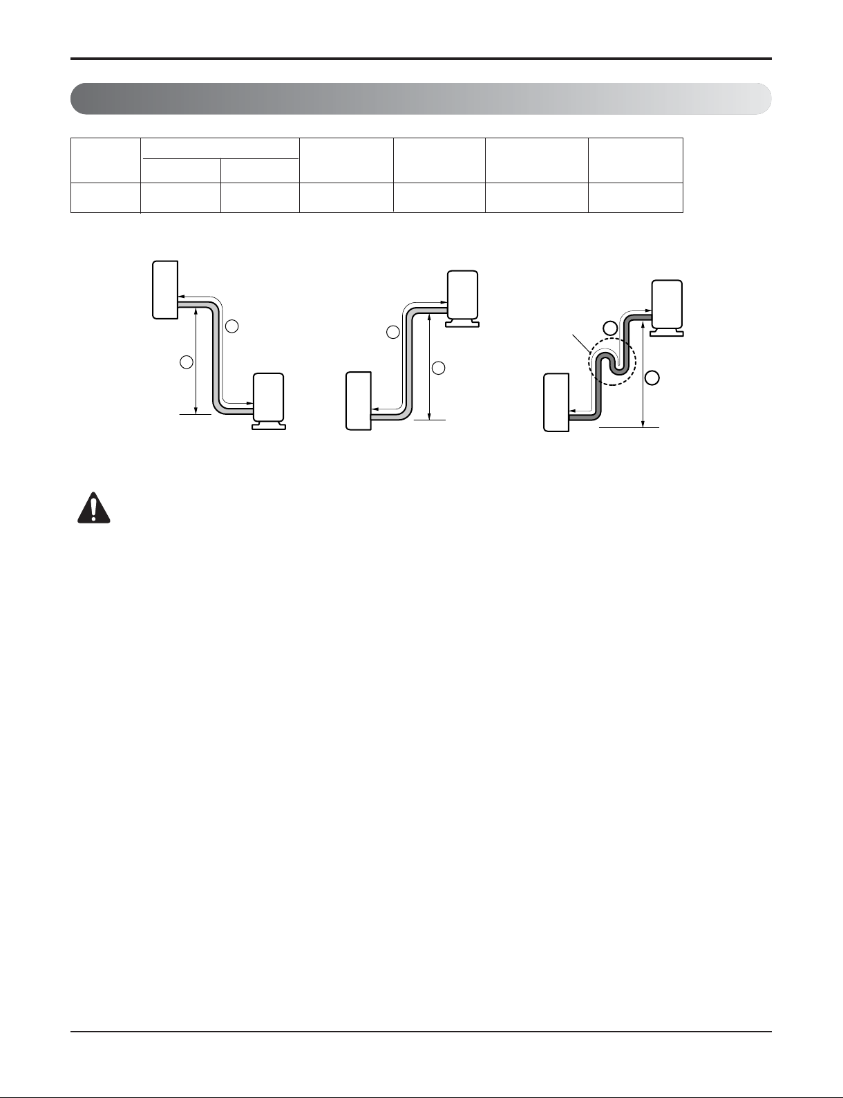
Piping Length and Elevation
Installation
Pipe Size
Capacity
(Btu/h)
Suction
Evap
Max.
length
Ⓐ
m(ft)
Additional
Refrigerant
g/m(oz/ft)
Max.
ElevationⒷ m(ft)
9k, 12k
Ø12.7mm(1/2") Ø6.35mm(1/4")
7.5(25) 7.5(25) 15(49) 20(0.22)
CAUTION: Capacity is based on standard length and maximum allowance length is
on the basis of reliability.
Oil trap should be installed every 16.4~23feets (5~7 meters).
Standard
Length m(ft)
Indoor unit
A
B
Outdoor unit
Outdoor unit
Indoor unit
A
B
Oil trap
Indoor unit
If piping length is more than 16.4ft(5m)
Outdoor unit
A
B
- 18 -
Copyright ©2010 LG Electronics. Inc. All right reserved.
Only for training and service purposes
LGE Internal Use Only
Installation
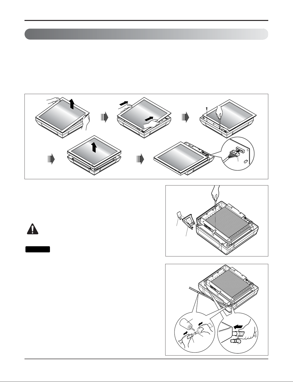
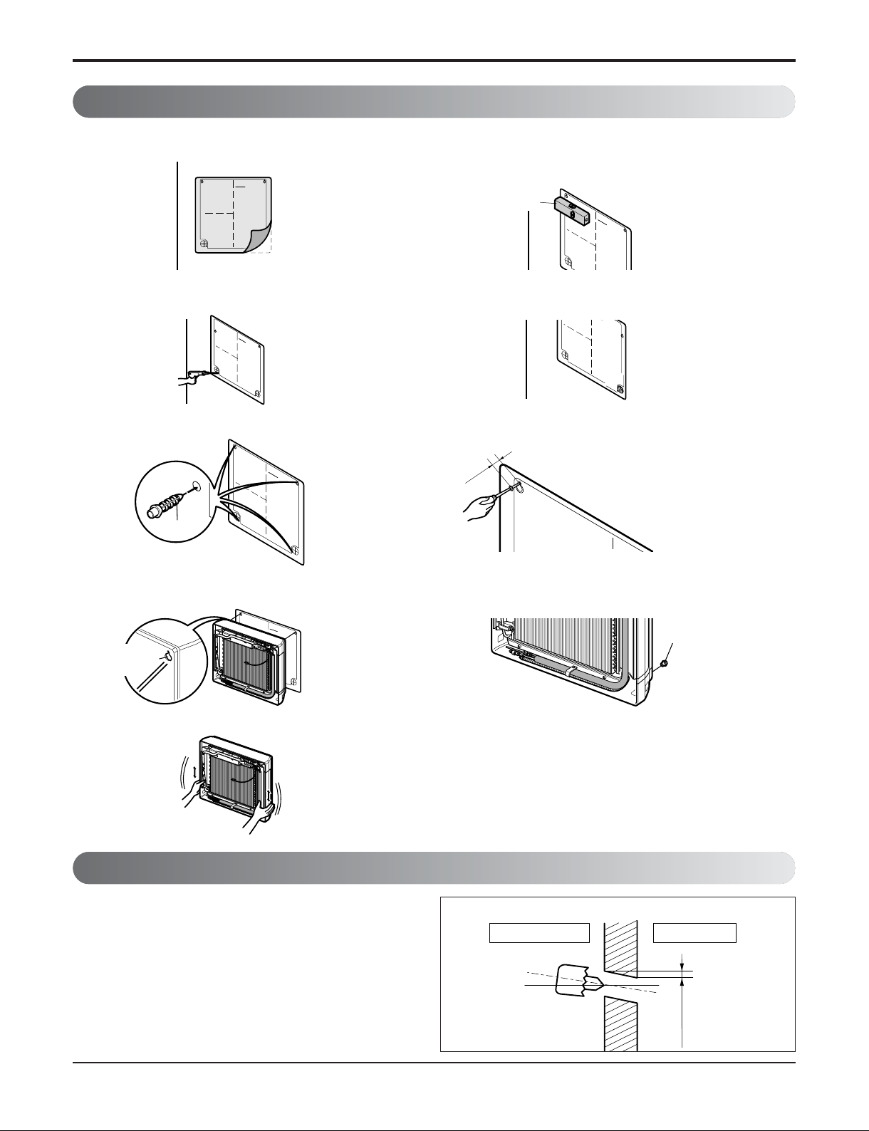
Preparing Work for Installation
Open panel front
1. Pull the upper part of the front panel.
2. Lift up the panel.
3. To detach the front panel, remove the two screws at the lower part.
4. Detach the front panel from the body.
5. To detach the panel, disconnect the connector at the upper part.
Cover pipe and cover side remove
1. Please remove the screw of the center tuning cover.
2. Pull up the side cover of desired connecting direction, then
cover side is separated.
3. Pick the pipe hole of the side cover.
CAUTION: After removing the pipe hole, cut
the burr for safety.
When making pipe path through rear
wall, you donʼt need to pick the pipe hole.
Drain hose junction
1. Remove the rubber stopple in the desired drain
direction.
2. Insert drain hose into the handle of drain pan, and
join drain hose and connecting hose according to the
figure by.
Panel Front
Connector
Side cover
Pipe hole
Only the
desired direction
rubber cap
Only the
desired direction
Connecting
part
Adhesive
Drain
hose
NOTICE
- 19 -
Copyright ©2010 LG Electronics. Inc. All right reserved.
Only for training and service purposes
LGE Internal Use Only
Installation
Fixing Indoor Unit
• Drill the piping hole with a ø50mm hole core drill.
Drill the piping hole at either the right or the left with
the hole slightly slanted to the outdoor side.
Drill a Hole in the Wall
5-7mm
(0.2~0.3")
Indoor
WALL
Outdoor
Plastic anchors
INSTALLATION GUIDE MAP
10mm
INSTALLATION GU
I
N
S
T
A
I
I
A
T
I
ON GUI
DE
M
A
P
Plastic anchors
INSTALLATION
GU
ID
E M
A
P
I
N
STA
LLATI
O
N
G
U
I
D
E MA
P
Hanger hole
(Rear side of
the product)
3. Make a hole with a diameter of 6mm and
depth of 30-35mm by piercing a screw
point.
5. Drive the fore plastic anchors into drilled
points.
7. Hang the hole of product at the upper
screws, and remove the map. (Falling
attention)
9. Check the fixed product with light power.
1. Attach an Installation guide map on the
desired surface.
2. Look at suited horizon by horizontal
meter on the horizontal setting line, and
fix lightly the map by adhesive tape.
4.
Drill the pierted part as a diameter of 50mm
for connecting piping. (In case of piercing
rear surface)
6.
First, Drive the two points of the upper
parts by screws. (Leave 10mm for hanging
the product)
8. Drive the lower parts after facing the hole
of product with plastic anchors, and fix
completely the upper screws.
10.
In case of nothing wrong, connect the
pipe and the wire. (Refer to installation
manual)
I
Horizontality
NSTAL
LA
TION G
UI
DE
M
AP
- 20 -
Copyright ©2010 LG Electronics. Inc. All right reserved.
Only for training and service purposes
LGE Internal Use Only
Flaring work and connection of piping
Flaring work and connection of piping
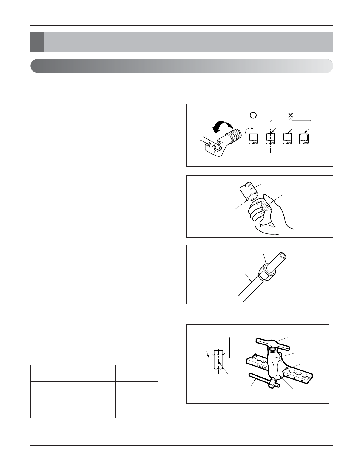
Flaring Work
Main cause for gas leakage is due to defect in flaring work. Carry out correct flaring work in the following
procedure.
Cutting the pipes and the cable.
1. Use the piping kit accessory or the pipes purchased
locally.
2. Measure the distance between the indoor and the
outdoor unit.
3. Cut the pipes a little longer than measured distance.
4. Cut the cable 4.9ft(1.5m) longer than the pipe length.
Removing burrs
1. Completely remove all burrs from the cut cross section
of pipe/tube.
2. Put the end of the copper tube/pipe in a downward
direction as you remove burrs in order to avoid
dropping burrs into the tubing.
Putting nut on
• Remove flare nuts attached to indoor and outdoor unit,
then put them on pipe/tube having completed burr
removal.
(not possible to put them on after flaring work)
Flaring work
1. Firmly hold copper pipe in a die in the dimension shown
in the table below.
2. Carry out flaring work with the flaring tool.
Copper
pipe
90°
Slanted Uneven Rough
Pipe
Reamer
Point down
Flare nut
Copper tube
mm inch mm
Ø6.35 1/4 1.1~1.3
Ø9.52 3/8 1.5~1.7
Ø12.7 1/2 1.6~1.8
Ø15.88 5/8 1.6~1.8
Ø19.05 3/4 1.9~2.1
Outside diameter A
Bar
Copper pipe
Clamp handle
Red arrow mark
Cone
Yoke
Handle
Bar
"A"
- 21 -
Copyright ©2010 LG Electronics. Inc. All right reserved.
Only for training and service purposes
LGE Internal Use Only
Flaring work and connection of piping
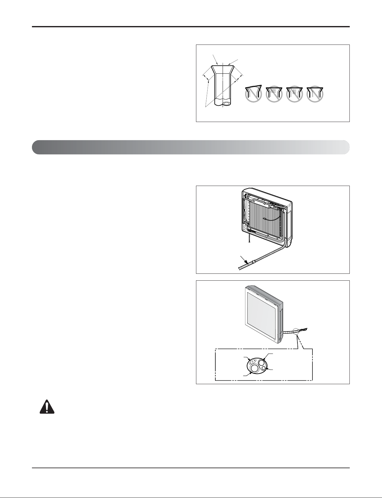
Check
1. Compare the flared work with the figure by.
2. If a flared section is defective, cut it off and do flaring
work again.
Indoor
Preparing the indoor unit's piping and drain hose for installation through the wall.
CAUTION: If the drain hose is routed inside the room, insulate the hose with an
insulation material* so that dripping from "sweating"(condensation) will not
damage furniture or floors.
*Foamed polyethylene or equivalent is recommended.
1. Route the indoor tubing and the drain hose in the
direction of rear left or right
2. Tape the tubing, drain hose and the connecting
cable. Be sure that the drain hose is located at the
lowest side of the bundle. Locating at the upper side
can cause drain pan to overflow inside the unit.
Inclined
Inside is shiny without scratches
Smooth all round
Even length
all round
Surface
damaged
Cracked Uneven
thickness
= Improper flaring =
Connecting the Piping
Drain hose
Connecting
cable
Gas side piping
Liquid side piping
Drain hose
Loop
- 22 -
Copyright ©2010 LG Electronics. Inc. All right reserved.
Only for training and service purposes
LGE Internal Use Only
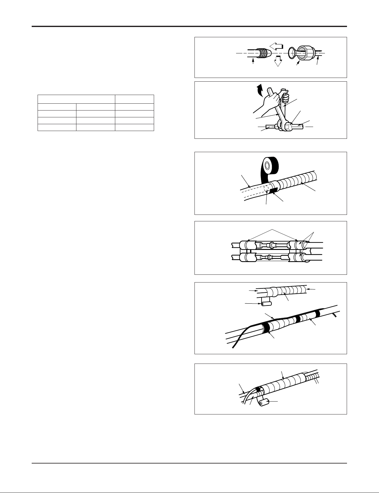
Connecting the piping with the indoor unit
and drain hose with drain pipe
1. Align the center of the pipings and sufficiently tighten
the flare nut by hand.
2. Tighten the flare nut with a wrench.
3. When extending the drain hose at the indoor unit,
install the drain pipe.
Wrap the insulation material around the
connecting portion.
1. Overlap the connection pipe insulation material and
the indoor unit pipe insulation material. Bind them
together with vinyl tape so that there may be no gap.
2. Wrap the area which accommodates the rear piping
housing section with vinyl tape.
3. Bundle the piping and drain hose together by
wrapping them with vinyl tape over the range within
which they fit into the rear piping housing section.
Flaring work and connection of piping
mm inch kgf.cm
Ø6.35 1/4 180~250
Ø9.52 3/8 340~420
Ø12.7 1/2 550~660
Outside diameter Torque
Wrap with vinyl tape
Drain hose
Pipe
Vinyl tape(wide)
Indoor unit tubing Flare nut Pipings
Torque wrench
Indoor unit tubing
Spanner (fixed)
Connection pipe
Flare nut
Vinyl tape(narrow)
Adhesive
Drain pipe
Indoor unit drain hose
Plastic bands
Insulation material
Vinyl tape(narrow)
Connection
pipe
Connecting cable
Vinyl tape
(wide)
Wrap with vinyl tape
Indoor
unit pipe
Pipe
- 23 -
Copyright ©2010 LG Electronics. Inc. All right reserved.
Only for training and service purposes
LGE Internal Use Only
Flaring work and connection of piping
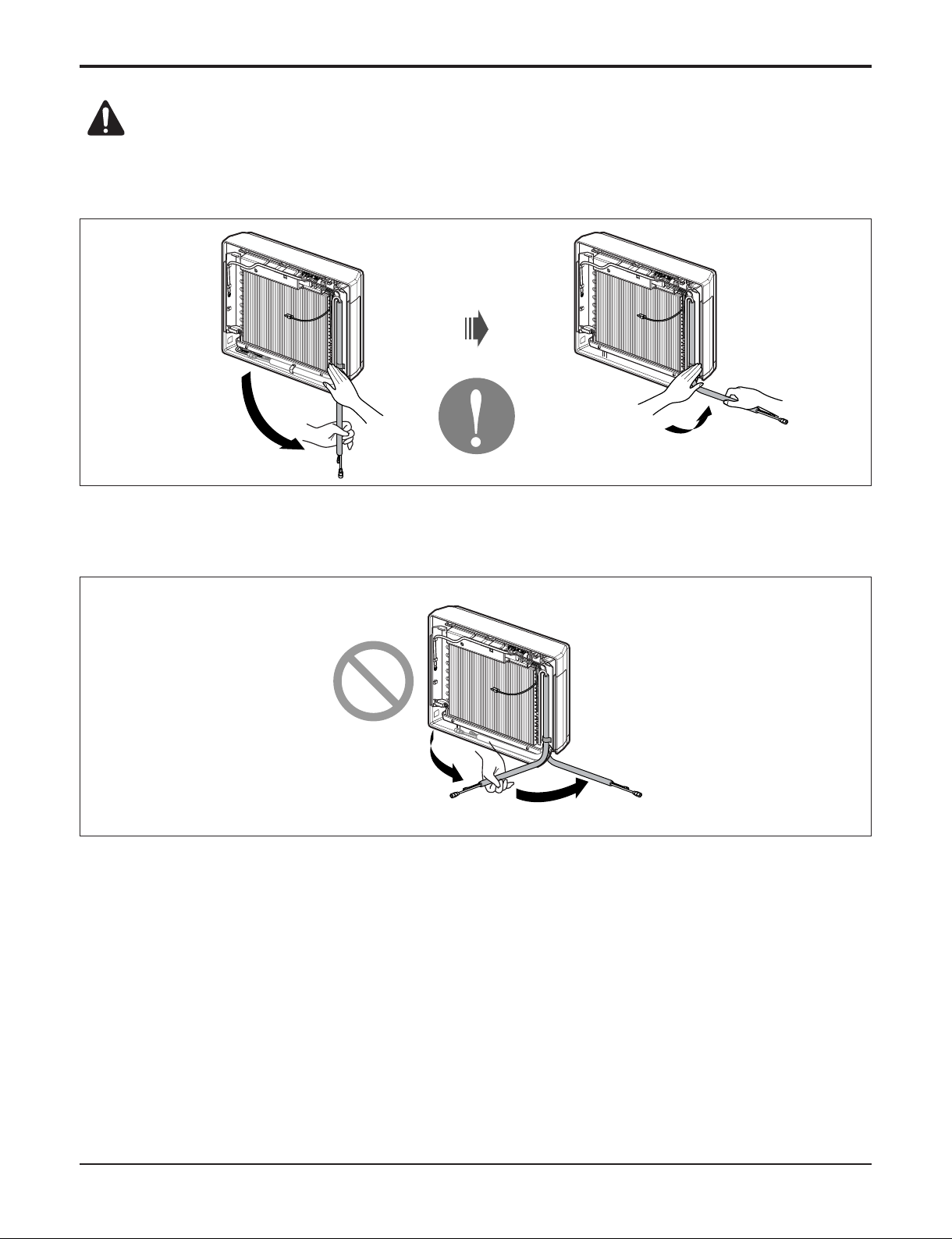
CAUTION: Installation Information
For right piping. Follow the instruction below.
Good case
• Press on the upper side of clamp and unfold the tubing to downward slowly.
Bad case
• Following bending type from left to right may cause damage to the turbing.
 Loading...