

Page 1

SERVICE MANUAL
Room Air Conditioner
MODELS : LA180CP
Page 2

Contents
Details of 2005 LG Model Name............................................................................................ 3
Functions................................................................................................................................ 4
Product References .............................................................................................................. 6
Dimensions............................................................................................................................. 7
Refrigeration Cycle Diagram................................................................................................. 9
Wiring Diagram..................................................................................................................... 10
Operation Details ................................................................................................................. 11
Display Function .................................................................................................................. 17
Self-diagnosis Function....................................................................................................... 17
Installation ............................................................................................................................ 18
Operation .............................................................................................................................. 32
Disassembly of the parts (Indoor Unit).............................................................................. 33
2-way, 3-way Valve................................................................................................................ 35
Cycle Troubleshooting Guide.............................................................................................. 42
Electronic Control Device.................................................................................................... 52
Schematic Diagram.............................................................................................................. 55
Exploded View and Replacement Parts List...................................................................... 57
-2-
Page 3
Details of 2005 LG Model Name
-3-
12
Code Type Code of Model Meaning
1 Producing Center/ A~Z
L: ChangWon R22, A: ChangWon R410A, C: ChangWon
R407C
Refrigerant
2 Type of Air conditioner A~Z S: Split Type Air conditioner
3 Cooling/Heating A~Z C: C/O, H: H/P, X: C/O + E/H, Z: H/P + E/H
4,5 Capacity(Btu/h) 1~9 Cooling/Heating Capacity
Ex. "09" ➔ 9,000Btu/h
6 Electric Range 1~9 Electric Standard
1 ➔ 115V/60Hz 6 ➔ 220~240V/50Hz
2 ➔ 220V/60Hz 7 ➔ 110V, 50/60Hz
3 ➔ 208~230V/60Hz 8 ➔ 380~415V/50Hz
5 ➔ 200~220V/50Hz 9 ➔ 380~415V/60Hz
7 Chassis A~Z Name of tool of unit
8 Color A~Z R: Mirror B: Blue N: Walut
W: White M: Metal C: Cherry
9 Function A~Z
10 Serial No. 0~9
-
Basic A
Basic + 4Way B
Plasma Filter C
Plasma Filter + 4Way D
Tele + LED + 4Way E
Tele + LCD + Plasma F + 4Way F
Tele Multi + LCD + Plasma F + 4Way G
Low A + Plasma F H
Low A + Plasma F + 4Way J
Plasma F + 4Way + Oxygen Generator K
A/change + Plasma F L
A/change + Plasma F + 4Way M
345678910
Page 4
-4-
Functions
• Room temperature sensor. (THERMISTOR)
• Maintains the room temperature in accordance with the Setting Temp.
• Indoor fan is delayed for 5 sec at the starting.
• Restarting is inhibited for approx. 3 minutes.
• High, Med, Low, CHAOS
• Intermittent operation of fan at low speed.
• The fan is switched to low(Cooling), med(Heating) speed.
• The unit will be stopped after 1, 2, 3, 4, 5, 6, 7 hours.
• The fan is switched to intermittent or irregular operation
•
The fan speed is automatically switched from high to low speed.
• The louver can be set at the desired position or swing
up and down automatically.
Indoor Unit
Operation ON/OFF by Remote controller
Sensing the Room Temperature
Room temperature control
Starting Current Control
Time Delay Safety Control
Indoor Fan Speed Control
Operation indication Lamps (LED)
Soft Dry Operation Mode
• Both the indoor and outdoor fan stops during defrosting.
• The indoor fan stops until the
evaporator pipe temperature will be reached
at 28°C.
Sleep Mode Auto Control
Natural Air Control by CHAOS Logic
Airflow Direction Control
Defrost(Deice) control (Heating)
Hot-start Control (Heating)
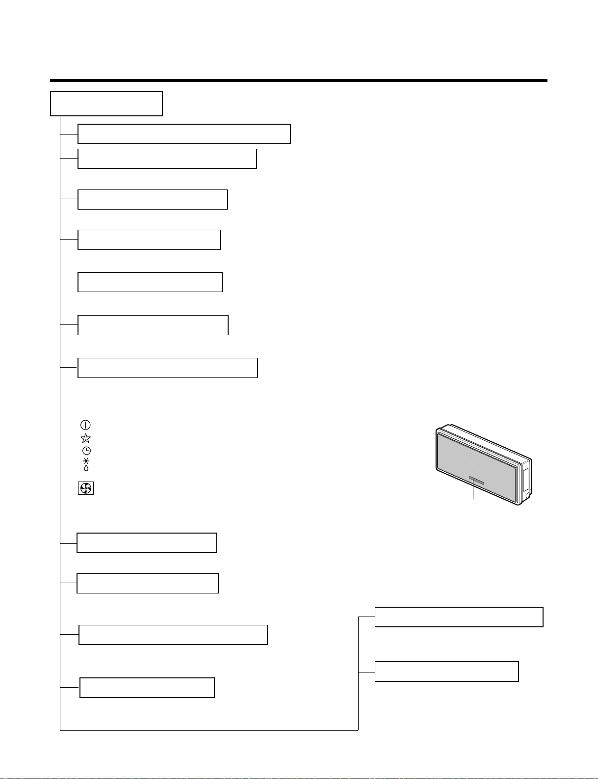
Signal Receptor
Receives the signals from the remote control.(Signal receiving sound: two short beeps or one long beep.)
Operation Indication Lamps
On/Off : Lights up during the system operation.
Sleep Mode : Lights up during Sleep Mode Auto operation.
Timer : Lights up during Timer operation.
Defrost Mode : Lights up during Defrost Mode or
Hot Start operation.(Heat pump model only)
Outdoor unit operation : Lights up during outdoor unit operation.
(Cooling model only)
Operation indication lamps
Page 5
-5-
Healthy Dehumidification Operation Mode.
( )
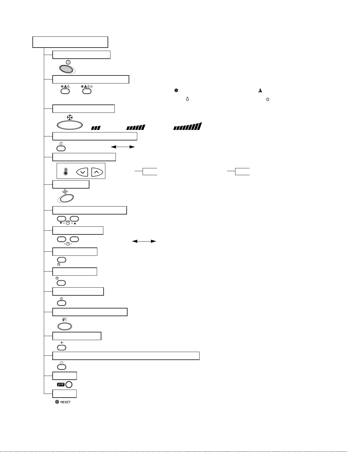
Remote Control
Operation ON/OFF
Reset
Operation Mode Selection
Temperature Setting
Timer Selection
Timer Setting
JET COOL
Timer Cancel
Sleep Operation
Airflow Direction Control
(Cooling
model only)
(Heating
model only)
TEMPERATURE
LOW HIGH
Cooling Operation Mode.( )
Heating Operation Mode.( )
Auto Operation Mode.( )
Air Circulation
Horizontal Airflow Direction Control Button(Optional)
Room, Temperature Checking
Setting the Time or Timer
Fan Speed Selection
(Low) (Med) (High)
ON
OFF
CANCEL
SET
2nd F
: (Low:11°C High:39°C)
: OFF, ON, OFF ON
: Cancel Sleep Mode, Timer ON or Timer OFF
: 1, 2, 3, 4, 5, 6, 7, Off Timer
: Fan Operates without cooling or heating.
Cooling
Down to 18°C
Up to 30°C
Heating
Down to 16°C
Up to 30°C
Page 6
-6-
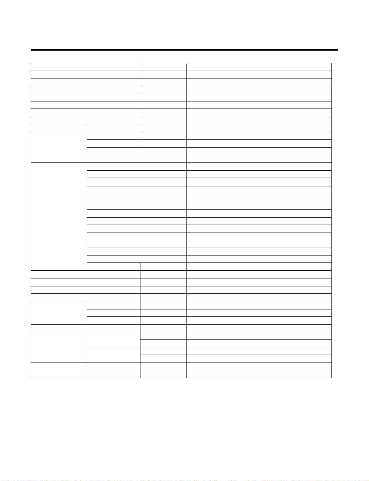
Product References
NOTE: Please refer to Label Quality on the product since this specification may be changed for improving
performance
Items Unit
LA180CP
Power Supply ø, V, Hz 1, 208/230, 60
Cooling Capacity BTU/h 18,000/18,000
Input W 1,900/1,900
Running Current A 9.0/9.0
COMP. Locked Rotor AMP. A 47
E.E.R BTU/hW 9.5/9.5
Air Circulation m3/min(cfm) 11.9(420)
Moisture Removal l/h(pts/hr) 2.5(5.3)
Noise Level Indoor, High dB(A)±3 45
(Sound Med dB(A)±3 42
Pressure, 1m) Low dB(A)±3 39
Outdoor, Max dB(A)±3 53
Features Temperature Control Thermistor
Air Deflection 4-way
Steps, Fan/Cool 3/4
Airflow Direction Control(up&down) Auto
Airflow Direction Control(left&right) Manual
Remocon Type Wireless LCD
Setting Temperature Range, Cooling Mode 64~86°F
Temperature Increment 2°F
Auto Operation(electronic control) Yes
Self Diagnosis Yes
Timer 24hr, On/Off
Sleep Operation Yes
Healthy Dehumidification Mode Yes
Restart Delay minutes 3
Refrigerant(R-22) Charge g(oz) 1,280(45.2)
Power cord AWG #: P*mm
2
14:3*2.5
Fuse or breaker Capacity A 20
Connecting Cable AWG #: P*mm
2
18:4*0.75
Connecting Tube Liquid Side mm(in) 6.35(1/4)
(ø. Socket Flare) Gas Side mm(in) 15.88(5/8)
Length, std m(ft) 7.5(24.6)
Additional Drain Hose(Outer Dia.) mm(in) 19(6/8)
Dimensions Indoor mm 928*522*147
(WxHxD) in 36.5*20.6*5.8
Outdoor mm 870*655*320
in 34.3*25.812.6
Net Weight Indoor kg(lbs) 16(35.3)
Outdoor kg(lbs) 58(127.9)
Page 7
-7-
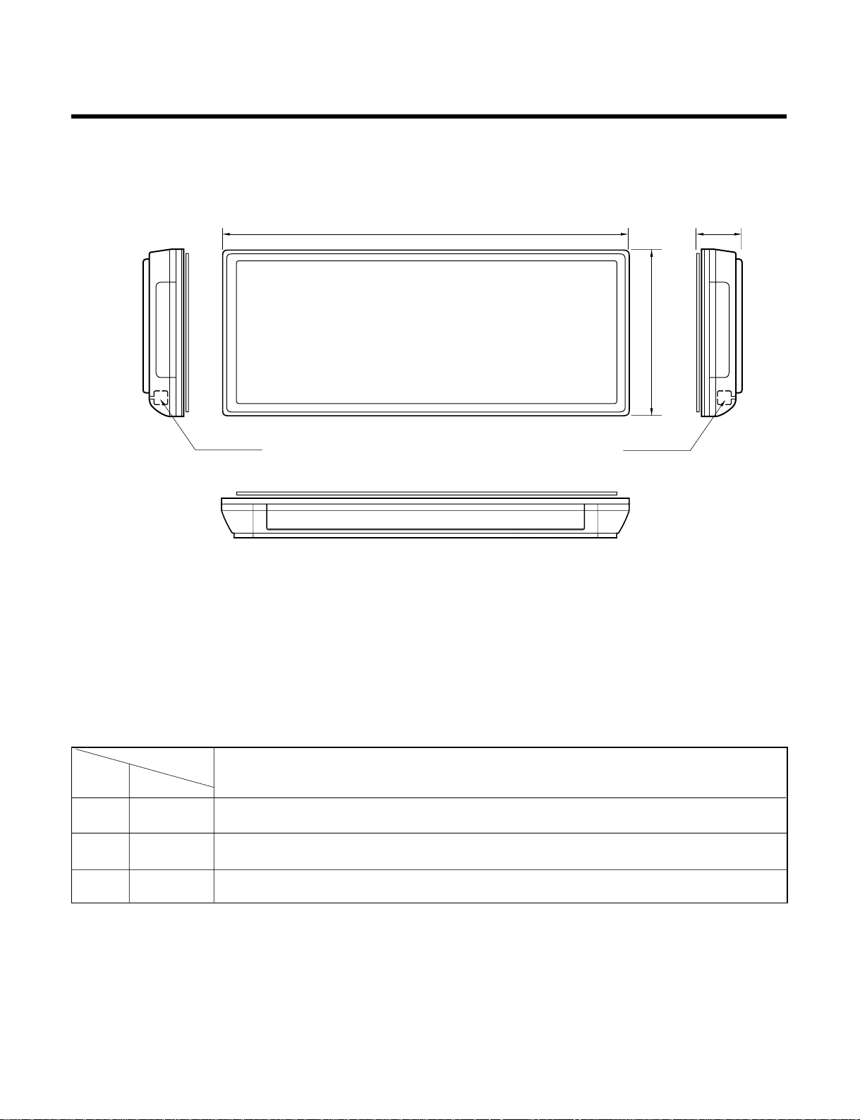
522
928
147
Pipe Hole Fix Hole
MODEL
DIM Unit
W mm(inch) 928(36.5)
H mm(inch) 522(20.6)
D mm(inch) 147(5.8)
Indoor Unit
Dimensions
(1) Indoor Unit
Page 8
-8-
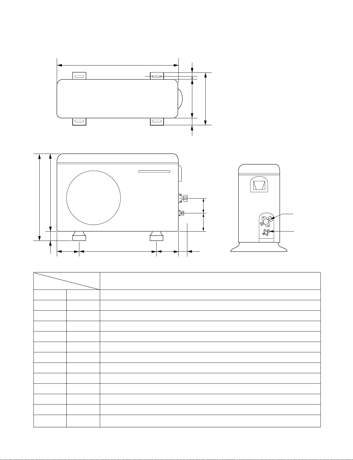
W
L6 L5 L7 L8
D
L1
L2
L9L10
L3L4
H
Gas side
3-way valve
Liquid side
3-way valve
(2) Outdoor Unit (18K)
MODEL
OUTDOOR UNIT
DIM
W mm(inch) 870(34.3)
H mm(inch) 655(25.8)
D mm(inch) 320(12.6)
L1 mm(inch) 370(14.6)
L2 mm(inch) 25(1.0)
L3 mm(inch) 630(24.8)
L4 mm(inch) 25(1.0)
L5 mm(inch) 546(21.5)
L6 mm(inch) 162(6.4)
L7 mm(inch) 162(6.4)
L8 mm(inch) 54(2.1)
L9 mm(inch) 74.5(2.9)
L10 mm(inch) 79(3.1)
Page 9
Refrigeration Cycle Diagram
-9-
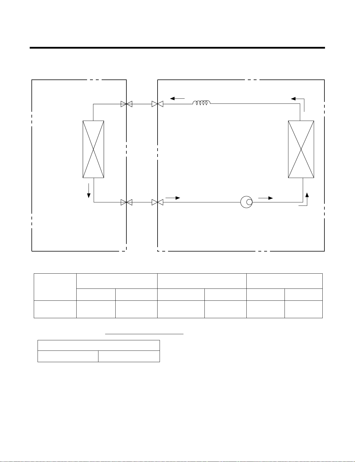
For installation over rated, *a proper quantity of refrigerant should be added for each meter.
Ex) 18K: When installed at a distance of 30m, 450g of
refrigerant should be added.
(30-7.5) x 20g = 450g
INDOOR UNIT
HEAT
EXCHANGER
(EVAPORATOR)
HEAT
EXCHANGER
(CONDENSER)
COMPRESSOR
GAS SIDE
CAPILLARY TUBE
LIQUID SIDE
OUTDOOR UNIT
• Cooling Only Models
MODEL
18K
(Cooling Only)
Pipe size(Diameter:ø) Piping length Elevation
Gas Liquid Rated Max Rated Max
5/8" 1/4" 7.5m(24.6ft) 30m(98.4ft) 5m(16ft) 7m(23ft)
a proper quantity of refrigerant
18K 20g
Page 10
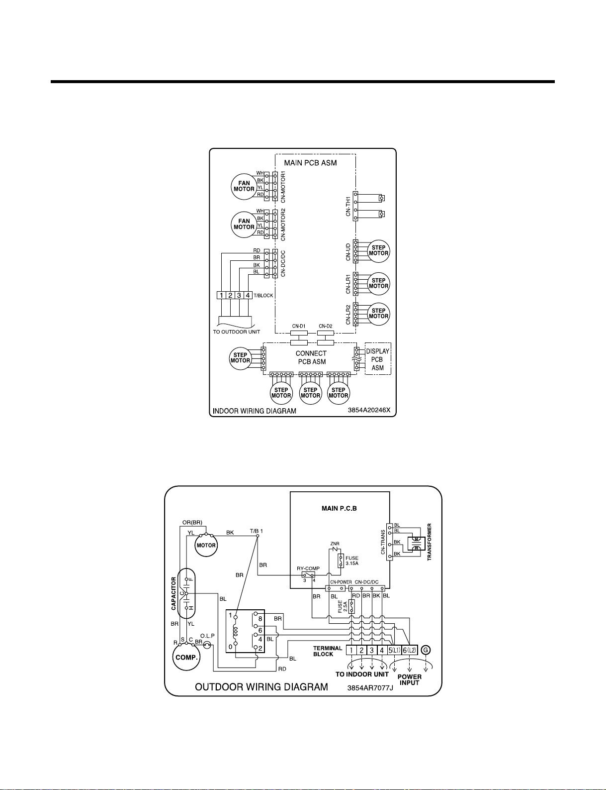
Wiring Diagram
-10-
(1) Indoor Unit
(2) Outdoor Unit (
18K)
18K (Cooling Only Models)
Page 11
Operation Details
1. MAIN UNIT FUNCTION
• DISPLAY
1) C/O Model
Operation Indicator
• ON while in appliance operation, OFF while in appliance pause.
• Flashing while in disconnection or short in Thermistor. (3 sec off / 0.5 sec on)
Sleep Timer Indicator
• ON while in sleep timer mode, OFF when sleep timer cancel or appliance operation pause.
Timer Indicator
• ON while in timer mode (on/off), OFF when timer mode is completed or canceled.
Comp. Running Incidator
• While in appliance operation, ON while in outdoor unit compressor running, OFF while in compressor off.
2) H/P Model
Operation Indicator
• ON while in appliance operation, OFF while in appliance pause.
• Flashing while in disconnection or short in Thermistor. (3 sec off / 0.5 sec on)
Sleep Timer Indicator
• ON while in sleep timer mode, OFF when sleep timer cancel or appliance operation pause.
Timer Indicator
• ON while in timer mode (on/off), OFF when timer mode is completed or canceled.
Defrost Indicator
• OFF except when hot start during heating mode operation or while in defrost control.
■ Cooling Mode Operation
• When the intake air temperature reaches 0.5°C below the setting temp, the compressor and the outdoor fan
stop.
• When it reaches 0.5°C above the setting temp, they start to operate again.
Compressor ON Temp ➲ Setting Temp+0.5°C
Compressor OFF Temp ➲ Setting Temp-0.5°C
• While in compressor running, operating with the airflow speed set by the remote control. While in compressor
not running, operating with the low airflow speed regardless of the setting.
■ Healthy Dehumidification Mode
• When the dehumidification operation input by the remote control is received, the intake air temperature is
detected and the setting temp is automatically set according to the intake air temperature.
26°C ≤ Intake Air Temp ➲ 25°C
24°C ≤ Intake Intake Air Temp<26°C ➲ Intake Air Temp-1°C
18°C ≤ Intake Intake Air Temp<24°C ➲ Intake Air Temp-0.5°C
Intake Air Temp<18°C ➲ 18°C
-11-
Page 12

• While in compressor off, the indoor f an repeats low airflow speed and pause.
• While the intake air temp is between compressor on temp. and compressor off temp., 10-min dehumidifica-
tion operation and 4-min compressor off repeat.
Compressor ON Temp. ➲ Setting Temp+0.5°C
Compressor OFF Temp. ➲ Setting Temp-0.5°C
• In 10-min dehumidification operation, the indoor fan operates with the low airflow speed.
■ Heating Mode Operation
• When the intake air temp reaches +3°…above the setting temp, the compressor is turned off. When below
the setting temp, the compressor is turned on.
Compressor ON Temp. ➲ Setting Temp.
Compressor OFF Temp. ➲ Setting Temp.+3°C
• While in compressor on, the indoor fan is off when the indoor pipe temp. is below 20°C, when above 28°C , it
operates with the low or setting airflow speed. When the indoor pipe temp is between 20°C and 28°C, it operates with Super-Low(while in sleep mode, with the medium airflow speed).
• While in compressor off, the indoor fan is off when the indoor pipe temp is below 33°C, when above 35°C , it
operates with the low airflow speed.
• If overloaded while in heating mode operation, in order to prevent the compressor from OLP operation, the
outdoor fan is turned on/off according to the indoor pipe temp.
• While in defrost control, both of the indoor and outdoor fans are turned off.
■ Defrost Control
• While in heating mode operation in order to protect the evaporator pipe of the outdoor unit from freezing,
reversed to cooling cycle to defrost the evaporator pipe of the outdoor unit.
• After 40 min heating mode operation, at 4 min interval, whether to carry out defrost control or not and the time
of defrost control are determined according to the following conditions.
1) While in heating mode operation, the maximum of the indoor pipe temperature is measured and it is com-
pared with the present indoor pipe temperature to get the difference of the indoor pipe temperatures (=the
maximum temperature of indoor pipe ? the present temperature of indoor pipe), according to which, whether
to carry out defrost control or not is determined.
2) According to the need of defrost control shown above and the elapsed time of heating mode operation at that
moment, the defrost control time is determined.
3) When the determined time of defrost control is below 7 min, heating mode operation continues without carry-
ing out defrost control. According to the procedure stated above, the determination is made again. When the
defrost control time is 7 min or longer, defrost control is then carried out.
• While in defrost control, the minimum temp of the indoor pipe is measured and it is compared with the present
temp of the indoor pipe to get the difference of the indoor pipe temperatures (=the present temperature of the
indoor pipe ? the minimum temperature of the indoor pipe). When the difference is 5°C or higher, defrost control is completed and heating mode operation is carried out.
• While in defrost control, if the defrost time determined before the start of defrost control is completed, defrost
control stops and heating mode operation is carried out regardless of the above condition.
• When the indoor pipe temp is 42°C or above, defrost control is not carried out even if the condition is one of
the defrost conditions above.
• While in defrost control, the compressor is on and the indoor fan, the outdoor fan, and the 4 way valve are off.
-12-
Page 13

-13-
■ Fuzzy Operation (C/O Model)
• According to the temperature set by Fuzzy rule, when the intake air temp is 0.5°C or more below the setting
temp, the compressor is turned off. When 0.5°C or more above the setting temp, the compressor is turned on.
Compressor ON Temp ➲ Setting Temp + 0.5°C
Compressor OFF Temp ➲ Setting Temp + 0.5°C
• At the beginning of Fuzzy mode operation, the setting temperature is automatically selected according to the
intake air temp at that time.
26°C ≤ Intake Air Temp ➲ 25°C
24°C ≤ Intake Air Temp < 26°C ➲ Intake Air Temp + 1°C
22°C ≤ Intake Air Temp < 24°C ➲ Intake Air Temp + 0.5°C
18°C ≤ Intake Air Temp < 22°C ➲ Intake Air Temp
Intake Air Temp<18°C ➲ 18°C
• When the Fuzzy key (Temperature Control key) is input after the initial setting temperature is selected, the
Fuzzy key value and the intake air temperature at that time are compared to select the setting temperature
automatically according to the Fuzzy rule.
• While in Fuzzy operation, the airflow speed of the indoor fan is automatically selected according to the
temperature.
■ Fuzzy Operation (H/P Model)
• When any of operation mode is not selected like the moment of the power on or when 3 hrs has passed since
the operation off, the operation mode is selected.
• When determining the operation mode, the compressor, the outdoor fan, and the 4 way valve are off and only
the indoor fan is operated for 15 seconds. Then an operation mode is selected according to the intake air
temp at that moment as follows.
24°C ≤ Inatake Air Temp ➲ Fuzzy Operation for Cooling
21°C ≤ Inatake Air Temp<24°C ➲ Fuzzy Operation for Dehumidification
Inatake Air Temp<21°C ➲ Fuzzy Operation for Heating
• If any of the operation modes among cooling / dehumidification / heating mode operations is carried out for 10
sec or longer before Fuzzy operation, the mode before Fuzzy operation is operated.
1) Fuzzy Operation for Cooling
• According to the setting temperature selected by Fuzzy rule, when the intake air temp is 0.5°C or more below
the setting temp, the compressor is turned off. When 0.5°C or more above the setting temp, the compressor
is turned on.
Compressor ON Temp ➲ Setting Temp +0.5°C
Compressor OFF Temp ➲ Setting Temp + 0.5°C
• At the beginning of Fuzzy mode operation, the setting temperature is automatically selected according to the
intake air temp at that time.
26°C≤ Intake Air Temp ➲ 25°C
24°C≤ Intake Air Temp<26°C ➲ Intake Air Temp + 1°C
22°C≤ Intake Air Temp<24°C ➲ Intake Air Temp + 0.5°C
18°C≤ Intake Air Temp<22°C ➲ Intake Air Temp
Intake Air Temp<18°C ➲ 18°C
• When the Fuzzy key (Temperature Control key) is input after the initial setting temperature is selected, the
Fuzzy key value and the intake air temperature at that time are compared to select the setting temperature
automatically according to the Fuzzy rule.
• While in Fuzzy operation, the airflow speed of the indoor fan is automatically selected according to the temperature.
Page 14

-14-
2) Fuzzy Operation for Dehumidification
• According to the setting temperature selected by Fuzzy rule, when the intake air temp is 0.5°C or more below
the setting temp, the compressor is turned off. When 0.5°C or more above the setting temp, the compressor
is turned on.
Compressor ON Temp ➲ Setting Temp + 0.5°C
Compressor OFF Temp ➲ Setting Temp+0.5°C
• At the beginning of Fuzzy mode operation, the setting temperature is automatically selected according to the
intake air temp at that time.
26°C ≤ Intake Air Temp ➲ 25°C
24°C ≤ Intake Air Temp<26°C ➲ Intake Air Temp+1°C
22°C ≤ Intake Air Temp<24°C ➲ Intake Air Temp+0.5°C
18°C ≤ Intake Air Temp<22°C ➲ Intake Air Temp
Intake Air Temp<18°C ➲ 18°C
• When the Fuzzy key (Temperature Control key) is input after the initial setting temperature is selected, the
Fuzzy key value and the intake air temperature at that time are compared to select the setting temperature
automatically according to the Fuzzy rule.
• While in Fuzzy operation, the airflow speed of the indoor fan repeats the low airflow speed or pause as in
dehumidification operation.
3) Fuzzy Operation for Heating
• According to the setting temperature selected by Fuzzy rule, when the intake air temp is 3°C or more above
the setting temp, the compressor is turned off. When below the setting temp, the compressor is turned on.
Compressor ON Temp ➲ Setting Temp
Compressor OFF Temp ➲ Setting Temp + 3°C
• At the beginning of Fuzzy mode operation, the setting temperature is automatically selected according to the
intake air temp at that time.
20°C≤Intake Air Temp ➲ Intake Air Temp + 0.5°C
Intake Air Temp<20°C ➲ 20°C
• When the Fuzzy key (Temperature Control key) is input after the initial setting temperature is selected, the
Fuzzy key value and the intake air temperature at that time are compared to select the setting temperature
automatically according to the Fuzzy rule.
• While in Fuzzy operation, the airflow speed of the indoor fan is set to the high or the medium according to the
intake air temperature and the setting temperature.
■ Airflow Speed Selection
• The airflow speed of the indoor fan is set to high, medium, low, or chaos (auto) by the input of the airflow
speed selection key on the remote control.
■ On-Timer Operation
• When the set time is reached after the time is input by the remote control, the appliance starts to operate.
• The timer LED is on when the on-timer is input. It is off when the time set by the timer is reached.
• If the appliance is operating at the time set by the timer, the operation continues.
Page 15
-15-
■ Off-Timer Operation
• When the set time is reached after the time is input by the remote control, the appliance stops operating.
• The timer LED is on when the off-timer is input. It is off when the time set by the timer is reached.
• If the appliance is on pause at the time set by the timer, the pause continues.
■ Off-Timer ↔ On-Timer Operation
• When the set time is reached after the on/off time is input by the remote control, the on/off-timer operation is
carried out according to the set time.
■ Sleep Timer Operation
• When the sleep time is reached after <1,2,3,4,5,6,7,0(cancel) hr> is input by the remote control while in appli-
ance operation, the operation of the appliance stops.
• While the appliance is on pause, the sleep timer mode cannot be input.
• While in cooling mode operation, 30 min later since the star t of the sleep timer, the setting temperature
increases by 1°C. After another 30 min elapse, it increases by 1°C again.
• When the sleep timer mode is input while in cooling cycle mode, the airflow speed of the indoor fan is set to the
low.
• When the sleep timer mode is input while in heating cycle mode, the airflow speed of the indoor fan is set to
the medium.
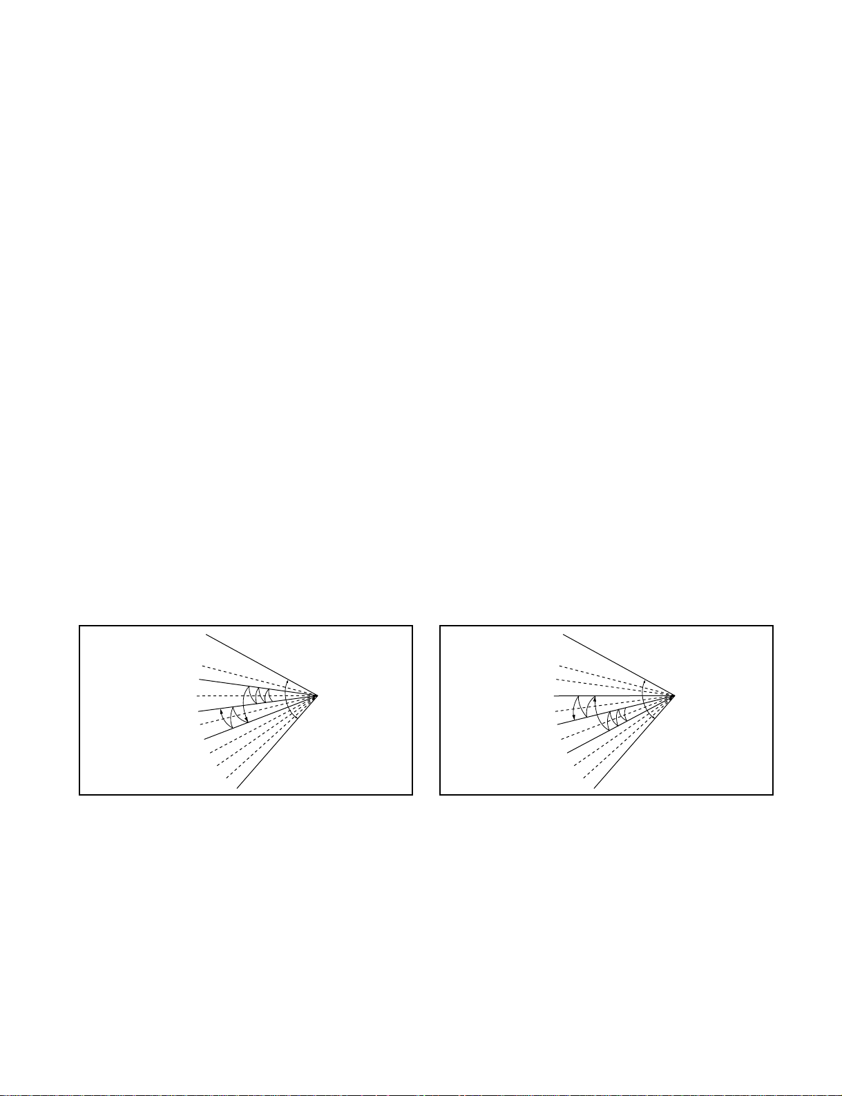
■ Chaos Swing Mode
• By the Chaos Swing key input, the louvers vane automatically operate with the Chaos Swing or they are fixed
to the desired direction.
• While in Chaos Swing mode, the angles of cooling and heating cycle operations are different.
■ Jet Cool Mode Operation (C/O Model)
• If the Jet Cool key is input at any operation mode while in appliance operation, the Jet Cool mode operates.
• In the Jet Cool mode, the indoor fan is operated at super-high speed for 30 min at cooling mode operation.
• In the Jet Cool mode operation, the room temperature is controlled to the setting temperature, 18°C
• When the sleep timer mode is input while in the Jet Cool mode operation, the Jet Cool mode has the priority.
• During the JET COOL function at any moment, the A/C starts to blow the cool air with side louvers closed at
extremely high speed for 30 minutes setting the room temp. automatically to 18°C.
CLOSED
OPEN
< Cooling Mode >
CLOSED
OPEN
< Heating Mode >
Page 16
-16-
■ Jet Cool Mode Operation (H/P Model)
• While in heating mode or Fuzzy operation, the Jet Cool key cannot be input. When it is input while in the other
mode operation (cooling, dehumidification, ventilation), the Jet Cool mode is operated.
• In the Jet Cool mode, the indoor fan is operated at super-high speed for 60 min at cooling mode operation.
• In the Jet Cool mode operation, the room temperature is controlled to the setting temperature, 18°C.
• When the sleep timer mode is input while in the Jet Cool mode operation, the Jet Cool mode has the priority.
• During the JET HEAT function at any moment, the A/C starts to blow the hot air with side louvers closed at
extremely high speed for 60 minutes setting the room temp. automatically to 30°C.
■ Forced Operation
• Operation procedures when the remote control can't be used.
• The operation will be started if the power button is pressed.
• If you want to stop operation, re-press the button.
• While in forced operation, the key input by the remote control has no effect and the buzzer sounds 10 times to
indicate the forced operation.
■ Test operation
•
During the TEST OPERATION, the unit operates in cooling mode at high speed fan, regardless of room temperature and resets in 18±1 minutes.
•
During test operation, if remote controller signal is received, the unit operates as remote controller sets.
If you want to use this operation, open the front panel upward and Press the power button let it be pressed for
about 3 seconds.
•
If you want to stop the operation, re-press the button.
■ Auto restart
•
In case the power comes on again after a power failure, Auto Restarting Operation is the function to operate
procedures automatically to the previous operating conditions.
■ Remote Control Operation Mode
• When the remote control is selected by the slide switch on the main unit, the appliance operates according to
the input by the remote control.
■ Protection of the evaporator pipe from frosting
• If the indoor pipe temp is below 0°C in 7 min. after the compressor operates without any pause while in cool-
ing cycle operation mode, the compressor and the outdoor fan are turned off in order to protect the indoor
evaporator pipe from frosting.
• When the indoor pipe temp is 7°C or higher after 3 min. pause of the compressor, the compressor and the
outdoor fan is turned on according to the condition of the room temperature.
■ Buzzer Sounding Operation
• When the appliance-operation key is input by the remote control, the short "beep-beep-" sounds.
• When the appliance-pause key is input by the remote control, the long "beep—" sounds.
• When a key is input by the remote control while the slide switch on the main unit of the appliance is on the
forced operation position, the error sound "beep-beep-beep-beep-beep-" is made 10 times to indicate that the
remote control signal cannot be received.
Heat pump Model
Cooling Model
Room Temp. ≥24°C21°C ≤ Room Temp. < 24°C Room Temp. < 21°C
Operating mode Cooling Cooling Healthy Dehumidification Heating
Indoor FAN Speed
High High High High
Setting Temperature
22°C 22°C 23°C 24°C
Page 17
-17-
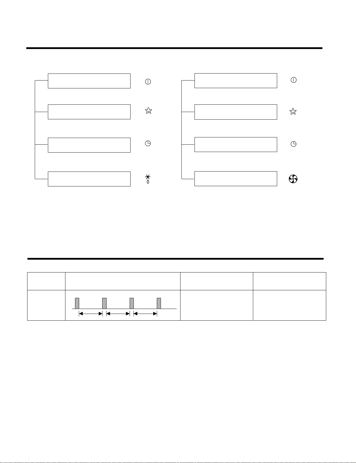
Display Function
Self-diagnosis Function
3sec 3sec 3sec
(once)
Error
Code
1
Error Display LED
(Indoor body operation LED)
Error contents
• Indoor room temperature
thermistor open/short
• Indoor pipe temperature
thermistor open/short.
• Indoor Thermistor
assembly check
SVC check point
1. Heating Model 2. Cooling Model
• Cooling, Soft Dry, Fan, Heating • Cooling, Soft Dry, Fan
• Sleep Mode • Sleep Mode
• Timer Mode • Timer Mode
• Hot-start, Defrost
Operation Indicator
Timer Indicator
Sleep Timer Indicator
Defrost Indicator
Operation Indicator
Timer Indicator
Sleep Timer Indicator
Compressor on Indicator
Page 18
Installation
1. Installation of indoor, Outdoor unit
-18-
Read completely , then f ollo w step by step.
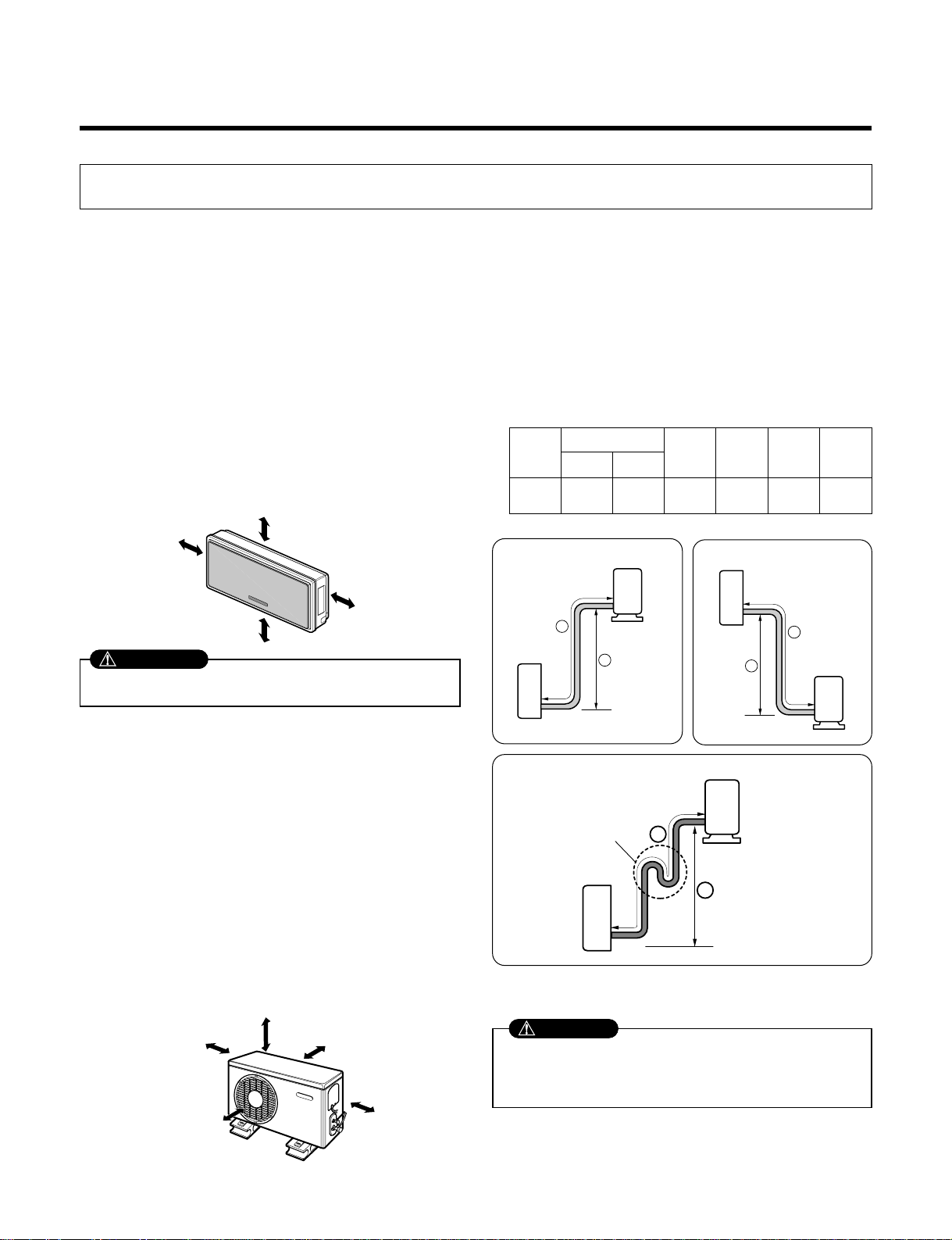
1) Select the best location
1. Indoor unit
■ Do not have any heat or steam near the unit.
■ Select a place where there are no obstacles in front
of the unit.
■ Make sure that condensation drainage can be conveniently routed away.
■ Do not install near a doorway.
■ Ensure that the space around the left and right of
the unit is more than 50cm(19.7”). The unit should
be installed as high on the wall as possible, allowing
a minimum of 10cm(3.9”) from ceiling.
■ Use a stud finder to locate studs to prevent unnecessary damage to the wall.
2. Outdoor unit
■ If an awning is built over the unit to prevent direct
sunlight or rain exposure, make sure that heat radiation from the condenser is not restricted.
■ Ensure that the space around the back and sides is
more than 10cm(3.9”).
The front of the unit should have more than
70cm(27.5”) of space.
■ Do not place animals and plants in the path of the
warm air.
■ Take the air conditioner weight into account and
select a place where noise and vibration are minimum.
■ Select a place so that the warm air and noise from
the air conditioner do not disturb neighbors.
■ Rooftop Installations:
If the outdoor unit is installed on a roof structure, be
sure to level the unit. Ensure the roof structure and
anchoring method are adequate for the unit location. Consult local codes regarding rooftop mounting.
2) Piping length and elevation
More than
10cm(3.9")
More than
50cm(19.7")
More than
2m(6.6ft)
More than
50cm(19.7")
More than 10cm(3.9") More than 10cm(3.9")
More
than 60cm(24")
More than 60cm(24")
More than 70cm(28")
In case more than 5m(16.4ft)
• Capacity is based on standard length and maximum allowance
length is on the basis of reliability.
• Oil trap should be installed every 5~7 meters(16.4~23ft).
Outdoor unit
Indoor unit
A
B
Outdoor unit
Indoor unit
A
B
A
Oil trap
Outdoor unit
Indoor unit
B
CAUTION
Install the indoor unit on the wall where the height from the floors
more than 2m(6.6ft).
CAUTION
18K 5/8" 1/4"
7.5 15 30
20
(24.6ft)
(49.2ft) (98.4ft)
Pipe Size
Capacity
(Btu/h)
GAS LIQUID
Max.
length
A
(m)
Additional
Refrigerant
(g/m)
Max.
Elevation
B
(m)
Standard
Length
(m)
Page 19
-19-
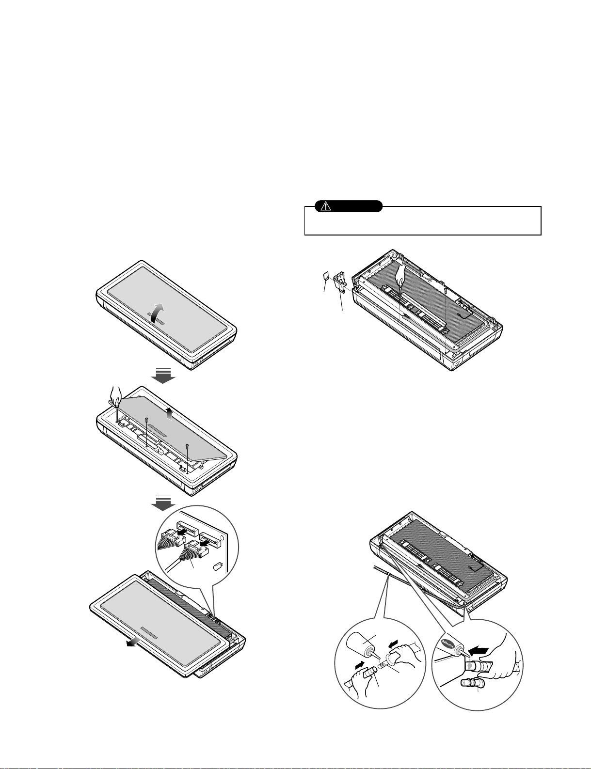
1. Open panel front
■ First,Pull the grille bottom, then remove screws(2
pieces), and close grille bottom again.
■ The moment of lifting the both lower parts of panel
front, you can hear sound this panel came out, In
this time panel front is separated
■ After pull down this panel a bit, and separate connecting wire with product.
Pipe hole
Side cover
Panel F ront
Connector
2. Cover pipe and cover side remove
■ Remove two screws(for fixing cover pipe)
■ Pull up the cover side of desired connecting direc-
tion, then cover side is separated.
■ In case connecting direction is left or right, path
through the hole of cover side.
When connecting pipe path through rear wall, don’t
remove the hole.
3. Drain hose junction
■ Remove the rubber stopple of desired drain direction.
■ As the following picture, Insert drain hose in the
handle of drain pan, and join drain hose and connecting hose.
rubber cap
Only one
desiring direction
Connecting
part
Adhesive
Drain
hose
3) Preparing work for Installation
After removing the pipe hole, cut the burr for safety.
CAUTION
Page 20

-20-
4) How to fix installation plate
The wall you select should be strong and solid enough
to prevent vibration
Mount the installation plate on the wall with
type "A" screws. If mounting the unit on a concrete
wall, use anchor bolts.
■ Mount the installation plate horizontally by aligning
the centerline using a level.
5) Preparing work for installation
1. Drill a hole in the wall
• Drill the piping hole with a ø50mm hole core drill.
Drill the piping hole at either the right or the left with
the hole slightly slanted to the outdoor side.
Installation Plate
240mm
(19.4")
240mm
(19.4")
60mm
(2.4")
60mm
(2.4")
Type "A" screw
Ø 70mm
(2.8")
Ø 70mm
(2.8")
5-7mm
(0.2~0.3")
Indoor
WALL
Outdoor
Measure the wall and mark the centerline. It is also
important to use caution concerning the location of
the installation plate-routing of the wiring to power
outlets is through the walls typically. Drilling the hole
through the wall for piping connections must be
done safely.
B
A
Page 21

-21-
2. Flaring Work and Connection of Piping
1) Flaring work
Main cause for refrigerant leakage is due to defect in
the flaring work. Carry out correct flaring work using the
following procedure.
1. Cut the pipes and the cable.
•
Use the piping kit accessory or pipes purchased locally.
•
Measure the distance between the indoor and the outdoor unit.
•
Cut the pipes a little longer than the measured distance.
•
Cut the cable 1.5m longer than the pipe length.
2. Burr removal
• Completely remove all burrs from the cut cross section of pipe/tube.
• Put the end of the copper tube/pipe in a downward
direction as you remove burrs in order to avoid dropping burrs into the tubing.
3. Putting nut on
• Remove flare nuts attached to indoor and outdoor
unit, then put them on pipe/tube having completed
burr removal.
(not possible to put them on after flaring work)
4. Flaring work
• Firmly hold copper pipe in a die in the dimension
shown in the table above.
• Carry out flaring work using flaring tool as shown
below.
5. Check
• Compare the flared work with figure below.
• If flare is noted to be defective, cut off the flared section and re-flare it.
2) Connection of piping Indoor
• Preparing the indoor unit's piping and drain hose for
installation through the wall.
1. Route the indoor tubing and the drain hose in the
direction of rear left or right.
Copper
pipe
90°
Slanted Uneven Rough
Bar
Copper pipe
Clamp handle
Red arrow mark
Cone
Yoke
Handle
Bar
"A"
Inclined
Inside is shiny without scratches
Smooth all round
Even length
all round
Surface
damaged
Cracked Uneven
thickness
= Improper flaring =
Pipe
Reamer
Point down
Flare nut
Copper tube
mm inch mm
Ø6.35 1/4 0~0.5
Ø9.52 3/8 0~0.5
Ø12.7 1/2 0~0.5
Ø15.88 5/8 0~1.0
Outside diameter A
Drain hose
Page 22

-22-
2.
Tape the tubing, drain hose, and the connecting
cable. Be sure that the drain hose is located at the
lowest side of the bundle. Locating at the upper side
can cause drain pan to overflow inside the unit.
NOTE: If the drain hose is routed inside the room,
insulate the hose with an insulation material* so that
dripping from "sweating"(condensation) will not damage
furniture or floors.
*Foamed polyethylene or equivalent is recommended.
3. Indoor unit installation
• Hook the indoor unit onto the upper portion of the
installation plate.(Engage the two hooks of the rear
top of the indoor unit with the upper edge of the installation plate.) Ensure that the hooks are properly seated on the installation plate by moving it left and right.
4. Connecting the pipings to the indoor unit and drain
hose to drain pipe.
• Align the center of the pipes and sufficiently tighten
the flare nut by hand.
• Tighten the flare nut with a wrench.
• When extending the drain hose at the indoor unit,
install the drain pipe.
5. Wrap the insulation material around the connecting
portion.
• Overlap the connection pipe insulation material and
the indoor unit pipe insulation material. Bind them
together with vinyl tape so that there is no gap.
• Wrap the area which accommodates the rear piping
housing section with vinyl tape.
• Bundle the piping and drain hose together by wrapping them with vinyl tape for enough to cover where
they fit into the rear piping housing section.
Connecting
cable
Gas side piping
Liquid side piping
Drain hose
Loop
Indoor unit tubing Flare nut Pipes
Wrench
Indoor unit tubing
Open-end wrench (fixed)
Connection pipe
Flare nut
Vinyl tape(narrow)
Adhesive
Drain pipe
Indoor unit drain hose
Plastic bands
Insulation material
Vinyl tape(narrow)
Connection
pipe
Connecting cable
Vinyl tape
(wide)
Wrap with vinyl tape
Indoor
unit pipe
Pipe
Drain hose
Connecting
cable
mm inch kg.m
Ø6.35 1/4 1.8
Ø9.52 3.8 4.2
Ø12.7 1/2 5.5
Ø15.88 5/8 6.6
Ø19.05 3/4 6.6
Outside diameter Torque
Wrap with vinyl tape
Drain hose
Pipe
Vinyl tape(wide)
Page 23

-23-
3) Connection of the pipes-Outdoor
1. Align the center of the pipings and sufficiently
tighten the flare nut by hand.
2. Finally, tighten the flare nut with torque wrench
until the wrench clicks.
• When tightening the flare nut with torque wrench,
ensure the direction for tightening follows the arrow on
the wrench.
Installation Information (For right piping)
• Good case
For right piping. Follow the instruction below.
■ Press on the upper side of clamp and
unfold the tubing to downward slowly.
• Bad case
■ Following bending type from left to right could cause
problem of pipe damage.
CAUTION
mm inch kg.m
Ø6.35 1/4 1.8
Ø9.52 3/8 4.2
Ø12.7 1/2 5.5
Ø15.88 5/8 6.6
Ø19.05 3/4 6.6
Outside diameter
Torque
Outdoor unit
Liquid side piping
(Smaller diameter)
Gas side
piping
(Bigger
diameter)
Torque wrench
Page 24

-24-
3. Connecting The Cable Between Indoor Unit and Outdoor Unit
1
Indoor Unit Outdoor Unit
2
3
4
1
2
3
4
5
6
G
To
branch
circuit
Ground
Power supply
a
L1
*
L2
Connecting cable(Low voltage)
b
Terminal
(4P)
Terminal
(6P)
Outdoor unit
Wiring Diagram
Terminal block
Over 5mm
(2")
Cover control
Conduit panel
Connecting
cable
Power supply
cord
*
L1 is neutral for 115V models.
1) Connection of the cable
1. Remove the cover control from the unit
by loosening the 3 screws.
2. Dismount caps on the conduit panel.
3. Temporarily mount the conduit tubes on
the conduit panel.
4. Properly connect both the power supply
and low voltage lines to the
corresponding terminals on the terminal
block.
5. Ground the unit in accordance with local
codes.
6. Be sure to size each wire allowing
several inches longer than the required
length for wiring.
7. Use lock nuts to secure the conduit
tubes.
1. shows field wiring.
2. Separately wire the high and low voltage line.
3. Use heat-proof electrical wiring capable of
withstanding temperatures up to 167°F.
4. Use outdoor and waterproof connection cable
rated more than 300V for the connection between
indoor and outdoor unit.
(For example, Type SJO-WA)
• Be sure to comply with local codes while
running the wire from the indoor unit to
the outdoor unit(size of wire and wiring
method, etc).
• Every wire must be connected firmly.
• No wire should be allowed to touch
refrigerant tubing, the compressor or any
moving parts.
Connector trade size for this unit is 1/2".
Refer to "How to connect wiring to the
terminals" for instructions on connecting
depending on the wire type you are using.
WARNING
NOTE
Power Supply
Model
Power source
18K 1ø, 208/230V 14 18 20A
AWG(MIN.)
ⓐⓑ
Fuse or breaker
Capacity
NOTE
Page 25

-25-
G
Terminal
block
Cap
(Remove)
Clamp cord
Lock nut
Conduit panel
Loop
Round
terminal
Screw with
special washer
Screw with
special washer
Round terminal
Terminal plate
Wire
Wire
Round terminal
Insulation
Strip 25mm(15/16")
Strip 10mm(3/8")
Solid wire
Cap(Reuse)
Taping
(for sealing)
Low voltage line
(connecting cable)
Power supply line
(1ø, 115V, 208/230V)
Hole
(for low voltage line)
Strand wire
2) Connection method of the connecting
cable(Example)
(1) Dismount two-caps on the conduit panel.
(2) Make a hole appropriate for the passage of
connection cable through on cap by tool.
(for low voltage line)
(3) Pass the connecting cable through the hole.
(4)
Properly connect the cable on the terminal block.
(5) Fix the connection cable with clamp cord
provided on the unit not to have strain at the
terminal when the connection cable is pulled
outside up to a 35 pound weight.
(6) Wind the vinyl tape round the connecting cable
for sealing between the surface of the
connection cable and cap.
(7) Mount the taped part of cable on the cap.
(8) Finally, mount the holed cap with the
wound cable on the conduit panel.
When connecting each power wire to the
corresponding terminal, follow instructions "How to
connect wiring to the terminals" and fasten the wire
tightly with the fixing screw of the terminal plate.
How to connect wiring to the terminals
■ For solid core wiring (or F-cable)
(1) Cut the wire end with a wire cutter of wire-
cutting pliers, then strip the insulation to expose
the solid wire about 25mm(15/16")
(2) Using a screwdriver, remove the terminal
screw(s) on the terminal plate.
(3) Using pliers, bend the solid wire to from a loop
suitable for the terminal screw.
(4) Shape the loop wire properly, place it on the
terminal plater and tighten securely with the
terminal screw using a screwdriver.
■ For strand wiring
(1) Cut the wire end with a wire cutter or wire-
cutting pliers, then strip the insulation to expose
the strand wiring about 10mm(3/8").
(2) Using a screwdriver, remove the terminal
screw(s) on the terminal plate.
(3) Using a round terminal fastener or pliers,
securely clamp each stripped wire end with a
round terminal.
(4) Position the round terminal wire, and replace
and tighten the terminal screw using a
screwdriver.
Loose wiring may cause the terminal to
overheat or result in unit malfunction. A fire
hazard may also exist. Therefore, be sure all
wiring is tightly connected.
WARNING
Page 26

-26-
4. checking the Drainage and forming the pipings
2) Form the piping
1. Form the piping by wrapping the connecting portion of the indoor unit with insulation material and
secure it with two kinds of vinyl tapes.
■ If you want to connect an additional drain hose, the
end of the drain outlet should be routed above the
ground. Secure the drain hose appropriately.
2. In cases where the outdoor unit is installed below
the indoor unit perform the following.
■ Tape the piping, drain hose and connecting cable
from down to up.
■ Secure the tapped piping along the exterior wall
using saddle or equivalent.
Taping
Drain hose
Pipings
Connecting cable
Trap is required to prevent water
from entering into electrical parts.
Seal small openings
around pipings with a
gum type sealer.
3. In cases where the Outdoor unit is installed above
the Indoor unit perform the following.
■ Tape the piping and connecting cable from down to
up.
■ Secure the taped piping along the exterior wall.
Form a trap to prevent water entering the room.
■ Fix the piping onto the wall by saddle or equivalent.
Seal a small opening
around the pipings
with gum type sealer.
Trap
Trap
1) Checking the drainage
1. To check the drainage.
■ Pour a glass of water on the evaporator.
■ Ensure the water flows through the drain hose of the
indoor unit without any leakage and goes out the
drain exit.
2. Drain piping
■ The drain hose should point downward for easy
drain flow.
■ Do not make drain piping.
Downward slope
Do not raise
Accumulated
drain water
Tip of drain hose
dipped in water
Air
Waving
Water
leakage
Water
leakage
Ditch
Less than
50mm gap
Water
leakage
Page 27

-27-
CAUTION
CAUTION
Air
Conditioner
Circuit Breaker
Use a circuit
breaker or time
delay fuse.
Main power source
If a power plug is not to be used, provide a circuit breaker between power source and the
unit as shown below.
3) Connect the cable to the indoor unit
1. Connect the wires to the terminals on the
control board individually according to the
outdoor unit connection.
• Ensure that the color of the wires of outdoor unit
and the terminal No. are the same as those of
indoor unit respectively.
(Refer to Wiring diagram on page10.)
• Be sure to refer to the wiring diagram label
inside the grille and carry out the correct
field wiring.
Wrong wiring can cause the unit to misoperate
to result in a fire hazard.
• Check local electrical codes and any specified
wiring instructions or limitations.
WARNING
Connecting cable
Page 28

-28-
To avoid nitrogen entering the refrigerant system in a
liquid state, the top of the cylinder must be higher than
its bottom when you pressurize the system. Usually,
the cylinder is used in a vertical standing position.
1) Air purging
Air and moisture remaining in the refrigerant system
have undesirable effects as indicated below.
• Pressure in the system rises.
• Operating current rises.
• Cooling(or heating) efficiency drops.
• Moisture in the refrigerant circuit may freeze and block
capillary tubing.
• Water may lead to corrosion of parts in the refrigeration system.
Therefore, the indoor unit and tubing between the
indoor and outdoor unit must be leak tested and evacuated to remove any noncondensables and moisture
from the system.
2) Air purging with vacuum pump
1. Preparation
• Check that each tube(both liquid and gas side tubes)
between the indoor and outdoor units have been properly connected and all wiring for the test run has been
completed. Remove the service valve caps from both
the gas and the liquid side on the outdoor unit. Note
that both the liquid and the gas side service valves on
the outdoor unit are kept closed at this stage.
2. Leak test
• Connect the manifold valve(with pressure gauges)
and dry nitrogen gas cylinder to this service port with
charge hoses.
• Pressurize the system to no more than 150 P.S.I.G.
with dry nitrogen gas and close the cylinder valve
when the gauge reading reached 150 P.S.I.G. Next,
test for leaks with liquid soap.
• Do a leak test of all joints of the tubing(both indoor
and outdoor) and both gas and liquid side service
valves.
Bubbles indicate a leak. Be sure to wipe off the soap
with a clean cloth.
• After the system is found to be free of leaks, relieve
the nitrogen pressure by loosening the charge hose
connector at the nitrogen cylinder. When the system
pressure is reduced to normal, disconnect the hose
from the cylinder.
Lo Hi
Indoor unit
Outdoor unit
Manifold valve
Charge hose
Nitrogen gas
cylinder(in vertical
standing position)
Pressure
gauge
5. Air Purging
Be sure to use a manifold valve for air purging. If it is
not available, use a stop valve for this purpose. The
"Hi" knob of the manifold valve must always be kept
close.
CAUTION
CAUTION
Page 29

-29-
3. Evacuation
• Connect the charge hose end described in the preceding steps to the vacuum pump to evacuate the tubing and indoor unit.
Confirm the "Lo" knob of the manifold valve is open.
Then, run the vacuum pump.
The operation time for evacuation varies with tubing
length and capacity of the pump. The following table
shows the time required for evacuation.
• When the desired vacuum is reached, close the "Lo"
knob of the manifold valve and stop the vacuum
pump.
4. Finishing the job
• With a service valve wrench, turn the valve stem of
liquid side valve counter-clockwise to fully open the
valve.
• Turn the valve stem of gas side valve counter-clockwise to fully open the valve.
• Loosen the charge hose connected to the gas side
service port slightly to release the pressure, then
remove the hose.
• Replace the flare nut and its bonnet on the gas side
service port and fasten the flare nut securely with an
adjustable wrench. This process is very important to
prevent leakage from the system.
• Replace the valve caps at both gas and liquid side
service valves and fasten them tight.
This completes air purging with a vacuum pump.
The air conditioner is now ready to test run.
(1) Remove the caps from the 2-way and 3-way
valves.
(2) Remove the service-port cap from the 3-way valve.
(3) To open the 2-way valve tur n the valve stem coun-
terclockwise approximately 90°, wait for about 2~3
sec, and close it.
(4) Apply a soap water or a liquid neutral detergent on
the indoor unit connection or outdoor unit connec-
tions by a soft brush to check for leakage of the
connecting points of the piping.
(5) If bubbles come out, the pipes have leakage.
Soap water method
Required time for evacuation when 30 gal/h vacuum pump is
used
10 min. or more 15 min. or more
If tubing length is less than 10m
(33 ft)
if tubing length is longer than 10m
(33 ft)
Gas side
Liquid side
Cap
Hexagonal wrench
2-way valve
(Open)
3-way valve
(Close)
Indoor unit
Pressure
gauge
Open
Outdoor unit
Manifold valve
Lo Hi
Close
Vacuum pump
Page 30

-30-
1. First, Check the side cover assembly exactly, Fix
power cord in the bottom groove of cover side
left.
2. Assemble connecting lead wire with controller
and first fix the upper part of panel front, then
match the lower part of panel front
3. Drive three screws.
Panel F ront
Connector
6. Panel Front Assembly
Page 31

-31-
1. Check that all tubing and wiring have been properly
connected.
2. Check that the gas and liquid side service valves are
fully open.
1. Prepare remote control
1. Remove the battery cover
by pulling it according to the
arrow direction.
2. Insert new batteries making
sure that the (+) and (–) of
battery are installed correctly.
3. Reattach the cover by
pushing it back into position.
NOTE:
• Use 2 AAA(1.5volt) batteries. Do not use recharge-
able batteries.
• Remove the batteries from the remote control if the
system is not going to be used for a long time.
2. Settlement of outdoor unit
• Anchor the outdoor unit with a bolt and nut(ø10mm)
tightly and horizontally on a concrete or rigid mount.
• When installing on the wall, roof or rooftop, anchor the
mounting base securely with a nail or wire assuming
the influence of wind and earthquake.
• In the case when the vibration of the unit is conveyed
to the hose, secure the unit with an anti-vibration
bushing.
3. Evaluation of the performance
Operate unit for 15~20 minutes, then check the system
refrigerant charge:
1. Measure the pressure of the gas side service valve.
2. Measure the temperature of the intake and discharge
of air.
3. Ensure the difference between the intake temperature and the discharge is more than 8°C(46°F) (Cooling) or (Heating).
4. For reference; the gas side pressure of optimum condition is as below.(Cooling)
NOTE: If the actual pressure is higher than shown, the
system is most likely over-charged, and charge
should be removed. If the actual pressure are
lower than shown, the system is most likely
undercharged, and charge should be added.
The air conditioner is now ready for use.
Bolt
Tubing connection
Discharge air
Discharge
temperature
Intake temperature
7. Test Running
R-22 35°C (95°F) 4~5kg/cm2G(56.8~71.0 P.S.I.G.)
Outside ambient
TEMP.
Refrigerant
The pressure of the gas side
service valve.
This is performed when the unit is to be relocated
or the refrigerant circuit is serviced.
Pump Down means collecting all refrigerant in the
outdoor unit without loss in refrigerant gas.
CAUTION:
Be sure to perform Pump Down procedure with the
unit cooling mode.
Pump Down Procedure
1. Connect a low-pressure gauge manifold hose to
the charge port on the gas side service valve.
2. Open the gas side service valve halfway and purge
the air from the manifold hose using the refrigerant
gas.
3. Close the liquid side service valve(all the way in).
4. Turn on the unit's operating switch and start the
cooling operation.
5. When the low-pressure gauge reading becomes 1
to 0.5kg/cm2 G(14.2 to 7.1 P.S.I.G.), fully close the
gas side valve stem and then quickly turn off the
unit. At that time, Pump Down has been completed
and all refrigerant gas will have been collected in
the outdoor unit.
PUMP DOWN
Page 32

-32-
Operation
Name and Function-Remote Control
The remote control transmits the signals to the system.
START/STOP BUTTON
Operation starts when this button is pressed and
stops when the button is pressed again.
OPERATION MODE SELECTION BUTTON
Used to select the operation mode.
ROOM TEMPERATURE SETTING BUTTONS
Used to select the room temperature.
INDOOR FAN SPEED SELECTOR
Used to select fan speed in four steps
low, medium, high and CHAOS.
JET COOL/HEATING
Used to start or stop the speed cooling/heating.
(speed cooling/heating operates super high fan speed
in cooling/heating mode)
CHAOS SWING BUTTON
Used to stop or start louver movement and set the
desired up/down airflow direction.
ON/OFF TIMER BUTTONS
Used to set the time of starting and stopping operation.
TIME SETTING BUTTONS
Used to adjust the time.
TIMER SET/CANCEL BUTTON
Used to set the timer when the desired time is obtained and to
cancel the Timer operation.
SLEEP MODE AUTO BUTTON
Used to set Sleep Mode Auto operation.
AIR CIRCULATION BUTTON
Used to circulate the room air without cooling or heating.
ROOM TEMPERATURE CHECKING BUTTON
Used to check the room temperature.
RESET BUTTON
Used prior to resetting time or after replacing batteries.
2nd F Button
Used prior to using modes printed in blue at the bottom of buttons.
1
2
345
678
9
10
11
12
13
14
AUTO CLEAN
ON
OFF
CANCEL
SET
1
3
5
4
9
10
14
7
2
8
13
11
6
12
Cooling Operation
Auto Operation
Healthy Dehumidification Operation
Heating Operation
•
Cooling Model( ), Heat Pump Model( )
Flip-up door
(opened)
Signal transmitter
Operation Mode
Page 33

-33-
Disassembly of the parts (Indoor unit)
Warning :
Disconnect the unit from power supply before making
any checks.
Be sure the power switch is set to “OFF”.
1. To remove the Grille from the Chassis.
- Push mark[ ] on the grille bottom then pull it down
and remove 3 securing screws.
- Lift the both lower parts of panel front.
- After pull down this panel a bit, separate connecting
wire with product.
2. To remove the Control Box.
- Before removing the control box, be sure to
disconnect the wires from PWB.
- Pull the cover control out from the control box
and disconnect other wires.
- Remove securing screws.
- Pull the control box out from the chassis carefully.
CN-TH1CN-UDCN-DC/DC
CN-LR2
CN-LR1
CN-MOTOR 1 (LEFT)
CN-MOTOR 2 (RIGHT)
Panel Front
Connector
∆
Page 34

-34-
3. To remove the Evaporator.
- Remove 1 screws securing the evaporator.
- Pull the evaporator out from the chassis carefully.
4. Before removing the Turbo Fan.
- Remove the securing screws from the chassis.
- Pull the pipe cover, top cover and the air guide.
5. To remove the Motor.
- Remove the securing bolt from the motor shaft.
- Pull the fan out from the motor shaft.
- Remove 4 screws securing motor mount from the
chassis and lift up the motor mount and the bracket.
Top Cover
Air Guide
Pipe Cover
Bolt
Motor Mount
Bracket
Turbo Fan
Page 35

2-way, 3-way Valve
2-way Valve (Liquid Side) 3-way Valve (Gas Side)
Shaft position Shaft position Service port
Closed Closed Closed
(with valve cap) (with valve cap) (with cap)
Open Closed Open
(counter-clockwise) (clockwise) (push-pin or with
vacumm pump)
Open Open Closed
(with valve cap) (with valve cap) (with cap)
Closed Open Open
(clockwise) (counter-clockwise) (connected manifold
gauge)
Open Open Open
(with charging
cylinder)
Open Open Open
(with charging
cylinder)
Open Open
Open Open
Works
Shipping
Air purging
(Installation)
Operation
Pumping down
(Transfering)
Evacuation
(Servicing)
Gas charging
(Servicing)
Pressure check
(Servicing)
Gas releasing
(Servicing)
1.
2.
3.
4.
5.
6.
Valve cap
Open position
Closed position
Pin
Service
port
Service
port cap
To outdoor unit
Flare nut
To
piping
connection
To outdoor unit
Hexagonal wrench (4mm)
Open position
Closed position
To
piping
connection
Flare nut
-35-
Open
(with charging cylinder)
Open
(with charging cylinder)
Page 36

1. Air purging
Required tools : hexagonal wrench, adjustable
wrench, torque wrenches, wrench to
hold the joints, and gas leak
detector.
The additional gas for air purging has been charged
in the outdoor unit.
However, if the flare connections have not be done
correctly and there gas leaks, a gas cylinder and the
charge set will be needed.
The air in the indoor unit and in the piping must be
purged. If air remains in the refrigeration pipes, it will
affect the compressor, reduce to cooling capacity, and
could lead to a malfunction.
• Procedure
(1) Recheck the piping connections.
(2) Open the valve stem of the 2-way valve
counterclockwise approximately 90°, wait 10
seconds, and then set it to closed position.
– Be sure to use a hexagonal wrench to operate
the valve stem.
(3) Check for gas leakage.
– Check the flare connections for gas leakage.
(4) Purge the air from the system.
– Set the 2-way valve to the open position and
remove the cap from the 3-way valve’s service
port.
– Using the hexagonal wrench to press the valve
core pin, discharge for three seconds and then
wait for one minute. Repeat this three times.
(5) Use torque wrench to tighten the service port
nut to a torque of 1.8kg.cm.
(6) Set the 3-way valve to the back seat.
(7) Mount the valve stem nuts to the 2-way and 3-
way valves.
(8) Check for gas leakage.
– At this time, especially check for gas leakage
from the 2-way and 3-way valve’s stem nuts,
and from the service port nut.
Caution
If gas leakage are discovered in step (3) above,
take the following mesures :
If the gas leaks stop when the piping connections
are tightened further, continue working from step (4).
If the gas leaks do not stop when the connections
are retightened, repair the location of the leak,
discharge all of the gas through the service por t,
and then recharge with the specified amount of
gas from a gas cylinder.
Service port nut:
Be sure, using a torque wrench to tighten the service port nut (after using the service port), so that it prevents the
gas leakage from the refrigeration cycle.
* CAUTION : Do not leak the gas in the air during Air purging.
Liquid side
Outdoor unit
3-way
valve
Gas side
Indoor unit
2-way
valve
Open
Clsed
-36-
Page 37

2. Pumping down
• Procedure
(1) Confirm that both the 2-way and 3-way valves
are set to the open position.
– Remove the valve stem caps and confirm that
the valve stems are in the raised position.
– Be sure to use a hexagonal wrench to operate
the valve stems.
(2) Operate the unit for 10 to 15 minutes.
(3) Stop operation and wait for 3 minutes, then
connect the charge set to the service port of
the 3-way valve.
– Connect the charge hose with the push pin to
the service port.
(4) Air purging of the charge hose.
– Open the low-pressure valve on the charge set
slightly to air purge from the charge hose.
(5) Set the 2-way valve to the closed position.
(6) Operate the air conditioner at the cooling
cycle and stop it when the gauge indicates
1kg/cm2g.
(7) Immediately set the 3-way valve to the closed
position.
– Do this quickly so that the gauge ends up
indicating 3 to 5kg/cm2g.
(8) Disconnect the charge set, and mount the 2-
way and 3-way valve’s stem nuts and the
service port nut.
– Use torque wrench to tighten the service por t
nut to a torque of 1.8 kg.m.
– Be sure to check for gas leakage.
Lo
Closed
Purge the air
Outdoor unit
Indoor unit
Liquid side
Gas side
CLOSE
Open
2-Way
valve
3-Way
valve
CLOSE
-37-
Page 38

1) Re-air purging
(Re-installation)
• Procedure
(1) Confirm that both the 2-way valve and the 3-
way valve are set to the closed position.
(2) Connect the charge set and a gas cylinder to
the service port of the 3-way valve.
– Leave the valve on the gas cylinder closed.
(3) Air purging.
– Open the valves on the gas cylinder and the
charge set. Purge the air by loosening the flare
nut on the 2-way valve approximately 45° for 3
seconds then closing it for 1 minute; repeat 3
times.
– After purging the air, use a torque wrench to
tighten the flare nut on the 2-way valve.
(4) Check for gas leakage.
– Check the flare connections for gas leakage.
(5) Discharge the refrigerant.
– Close the valve on the gas cylinder and
discharge the refrigerant until the gauge
indicates 3 to 5 kg/cm2g.
(6) Disconnect the charge set and the gas
cylinder, and set the 2-way and 3-way valves
to the open position.
– Be sure to use a hexagonal wrench to operate
the valve stems.
(7) Mount the valve stem nuts and the service
port nut.
– Use torque wrench to tighten the service por t
nut to a torque of 1.8 kg.m.
– Be sure to check for gas leakage.
* CAUTION:
Do not leak the gas in the air during Air
Purging.
Lo
Closed
OPEN
Closed
Gas cylinder
R22
Outdoor unit
Indoor unit
Liquid side
Gas side
CLOSE
2-Way
valve
3-Way
valve
-38-
Page 39

2) Balance refrigerant of the 2-way, 3-way valves
(Gas leakage)
• Procedure
(1) Confirm that both the 2-way and 3-way valves
are set to the back seat.
(2) Connect the charge set to the 3-way valve’s
port.
– Leave the valve on the charge set closed.
– Connect the charge hose with the push pin to
the service port.
(3) Open the valve (Lo side) on the charge set
and discharge the refrigerant until the gauge
indicates 0 kg/cm2G.
– If there is no air in the refrigerant cycle (the
pressure when the air conditioner is not
running is higher than 1 kg/cm2G), discharge
the refrigerant until the gauge indicates 0.5 to 1
kg/cm2G. if this is the case, it will not be
necessary to apply a evacuatin.
– Discharge the refrigerant gradually; if it is
discharged too suddenly, the refrigeration oil
will also be discharged.
Lo
Open
Open
3-Way
valve
2-Way
valve
Gas side
CLOSEOPEN
Outdoor unit
Liquid side
Indoor unit
-39-
Page 40

3. Evacuation
(All amount of refrigerant leaked)
• Procedure
(1) Connect the vacuum pump to the charge set’s
center hose
(2) Evacuation for approximately one hour.
– Confirm that the gauge needle has moved
toward -76 cmHg (vacuum of 4 mmHg or less).
(3) Close the valve (Lo side) on the charge set,
turn off the vacuum pump, and confirm that
the gauge needle does not move (approximately 5 minutes after turning off the vacuum
pump).
(4) Disconnect the charge hose from the vacuum
pump.
– Vacuum pump oil.
If the vacuum pump oil becomes dirty or
depleted, replenish as needed.
Lo
Open
Open
Vacuum pump
2-Way
valve
Outdoor unit
Liquid side
Indoor unit
Gas side
3-Way
valve
CLOSE
OPEN
-40-
Page 41

4. Gas Charging
(After Evacuation)
• Procedure
(1) Connect the charge hose to the charging
cylinder.
– Connect the charge hose which you dis-
connected from the vacuum pump to the valve
at the bottom of the cylinder.
– If you are using a gas cylinder, also use a scale
and revers the cylinder so that the system can
be charged with liquid.
(2) Purge the air from the charge hose.
– Open the valve at the bottom of the cylinder
and press the check valve on the charge set to
purge the air. (Be careful of the liquid
refrigerant). The procedure is the same if
using a gas cylinder.
(3) Open the valve (Lo side on the charge set and
charge the system with liquid refrigerant.
– If the system can not be charged with the
specified amount of refrigerant, it can be
charged with a little at a time (approximately
150g each time) while operating the air
conditioner in the cooling cycle; however, one
time is not sufficient, wait approximately 1
minute and then repeat the procedure
(pumping down-pin).
(4) Immediately disconnect the charge hose from
the 3-way valve’s service port.
– Stopping partway will allow the gas to be
discharged.
– If the system has been charged with liquid
refrigerant while operating the air conditioner
turn off the air conditioner before disconnecting
the hose.
(5) Mount the valve stem nuts and the service
port nut.
– Use torque wrench to tighten the service port
nut to a torque of 1.8 kg.m.
– Be sure to check for gas leakage.
\
This is different from previous procedures.
Because you are charging with liquid refrigerant
from the gas side, absolutely do not attempt to
charge with larger amounts of liquid refrigerant
while operating the air conditioner.
-41-
Indoor unit
Liquid side
Gas side
Check valve
Charging
cylinder
Lo
(1)
OPEN
CLOSE
Open
Outdoor unit
2-Way
valve
Open
3-Way
valve
Page 42

1. Trouble analysis
1. Check temperature difference between intake and discharge air and operating current.
Temp. Difference
Operating Current
Temp. difference :approx. 0°F
Current :less than 80% of
rated current
Temp. difference :approx. 8°C(14°F)
Current :less than 80% of
rated current
Temp. difference :less than 8°C(14°F)
Current :less than 80% of
rated current
Temp. difference :over 8°C(14°F)
All amount of refrigerant leaked out.
Check refrigeration cycle.
Refrigerant leakage
Clog of refrigeration cycle
Defective compressor
Excessive amount of refrigerant
Normal
Notice:
Temperature difference between intake and discharge air depends on room air humidity. When the room air
humidity is relatively higher, temperature difference is smaller. When the room air humidity is relatively lower
temperature difference is larger.
2. Check temperature and pressure of refrigeration cycle.
Notice:
1. The suction pressure is usually 4.5~5.0 kg/cm
2
G at normal condition.
2. The temperature can be measured by attaching the thermometer to the low pressure tubing and wrap it with
putty.
- 42 -
Cycle Troubleshooting Guide
Suction pressure
(Compared with the
normal value)
Temperature
(Compared with the
normal value)
Cause of Trouble Description
Higher
High
Defective compressor
Defective 4-way reversing valve
Excessive amount of refrigerant
High pressure does not quickly
rise at the beginning of operation.
Current is low.
Normal
Lower Higher
Insufficient amount of
refrigerant(Leakage)
Clogging
Current is low.
Current is low.
Page 43

- 43 -- 43 -
2. Product does not operate at all.
(* Refer to Electronic Control Device drawing and Schematic diagram.)
Turn off Main Power
Turn on Main Power
Does "beeping" sound is made from the Indoor Unit?
Primarily, the operating condition of Micom is OK.
Check the voltage of po wer(About A C 208V/A C230V, 60Hz)
• Main power's voltage
• Voltage applied to the unit
• Connecting method of Indoor/Outdoor connecting
cable
• Check PWB Ass'y(Outdoor unit)
- Fuse
- Pattern damage
- Varistor(ZNRI)
Check the connection housing for contacting
• Connector related to CN-POWER
• Connector related to CN-FAN
• Connector contacting of Outdoor Fan/Compressor
• Display PWB Ass'y Check
• Connector related to CN-DC/DC
Check each load(Indoor/Outdoor Fan Motor,
Compressor, Stepping Motor) and contacting
condition of related connector(including connecting
cable of Indoor/Outdoor Unit)
PCB Board Operation Check
Items
• Power Transformer
(Outdoor unit)
- Input Voltage
- Output Voltage
• IC2(7812) Output
(Indoor/Outdoor unit)
• IC3(7805) Output
(Indoor/Outdoor unit)
• IC4(KIA7036, Reset IC)
OSC01B(4MHz)
(Indoor/Outdoor unit)
• Replace Trans
• Replace IC2
• Replace IC3
• Replace faulty parts
- About AC208V/230V±10% - Check the power voltage
- About AC17±3V
• DC +12V
• DC +5V
• Voltage of Outdoor unit Micom No. 8,
Voltage of Indoor unit Micom No. 43 and soldering
condition
Content Remedy
NO
YES
(After 10 seconds)
Page 44

- 44 -
3. The product is not operate with the remote controller.
Turn on Main Power
While the compressor has been stopped, the compressor does not
operate owing to the delaying function for 3 minutes after stopped.
Caused by other parts except the remote controller
Cause by the remote controller
When the mark( ) is displayed in LCD screen, replace
battery .
Check the contact of CN-D1/D2 connector.
When the compressor stopped Indoor Fan is driven by a low speed.
At this point the wind speed is not controlled by the remote controller.
(When operated in the Sleeping Mode, the wind speed is set to the
low speed by force.)
Check DISP PWB Ass'y
- Voltage between CN-D2 - : DC +5V
When the detect switch(double k e y) inside the remote
controller door is fault, it is impossible to oper ate
temperature regulating( / ) and wind speed selecting.
Check the connecting circuit between the remote controller
MICOM (No. ) - R17(2Ω) - IR LED - Q1 - R16(2.2K Ω).
Check point
• Check the connecting circuit between PIN - R75(1K)
- C71(1000PF) - MICOM PIN
• Check Receiver Ass'y
Page 45

- 45 -
4. Compressor/Outdoor Fan are unable to drive.
Turn on Main Power
Operate "Cooling Mode( )" by setting the desired temperature of the
remote controller is less than one of the indoor temperature by 2°F at least.
When in Fan Mode, Compressor/Outdoor Fan is stopped.
Check the sensor for indoor temperature is attached as close as to be
effected by the temperature of Heat Exchanger(EVA).
When the sensor circuit for indoor temperature and connector are in bad
connection or are not engaged, Compressor/Outdoor Fan is stopped.
• Check the related circuit of R02(12.1K), R04(6.2K), Micom (No.27)
(Indoor unit).
• Check the indoor temper ature sensor is disconnected or not(About 10kΩ/ at 25°C).
When the temperature around Outdoor PWB Ass'y is above 163°F the
compressor is stop and only Outdoor Fan is operating.
Turn off Main Power
• Check the electrical wiring diagram of outdoor side.
• Check the abnormal condition for the component of Compressor/Outdoor
Fan Motor.
Check Relay(RY - COMP) for driving compressor.
• When the power(About AC200V) is applied to the connecting wire terminal
support transferred to compressor, PWB Ass'y is normal.
• Check the circuit related to the relay(Outdoor unit).
Check point COMP ON COMP OFF
Between Micom(No.
DC5V DC0V
15) and GND
Between IC8(No. 16)
Below DC 1V
About DC12V
and GND IC0M(No.16)
(app)
Page 46

- 46 -
5. When Indoor Fan does not operate.
Check connecting condition of the CN-MOTOR
CONNECTOR
Does the voltage of terminal of CN-DC/DC CONNECTOR in
Indoor unit corresponds to the values in the table of page 51?
Do the voltage of terminal of
CN-DC/DC CONNECTOR in
Outdoor unit corresponds to the
values in the table of page 51?
Check the patterns and the
conditions of outdoor unit
PWB Assy's.
Check the connecting
condition and disconnection
of connecting wires between
Indoor and Outdoor unit.
Check the pattern and the
condition of Indoor unit PWB
Ass'y.
Check the interference of Indoor Fan.
Does the voltage of each terminals of CN-MOTOR CONNECTOR in
Indoor unit corresponds to values in the Table of page 51?
Check the motor of Indoor Fan
Indoor Fan ma y be stopped in the Soft Dry Mode(change to the Cooling Operation Mode).
Indoor Fan is to be stopped when Indoor pipe(coil) termperature is lo wer than 79°F.
(At that times, Defrost indicator is turned on)
NO
YES
Page 47

- 47 -
• Confirm that the Vertical Louver is normally geared with the shaft of
Stepping Motor.
• If the regular torque is detected when rotating the Vertical Louver with
hands Normal
• Check the connecting condition of CN-U/D, CN-L/R Connector
• Check the soldering condition(on PWB) of CN-U/D, CN-L/R Connector
Check the operating circuit of the Vertical Louver
• Confirm that there is DC +12V between pin (RED) of CN-U/D, CN-L/R
and GND.
• Confirm that there is a soldering short at following terminals.
- Between 62 , 61 , 60 and 59 of MICOM
- Between 57 , 56 , 55 and 54 of MICOM
- Between
51 ,
50 , 49 and 48 of MICOM
- Between
1 , 2 , 3 , 4 and 5 of CN-U/D, CN-L/R
If there are no problems after above checks
• Confirm the assembly conditions that are catching and interfering parts in
the rotation radial of the Vertical Louver
6. When Vertical Louver does not operate.
Page 48

- 48 -
• The operation indicator of Indoor unit blinks five times.
• The red indicator of Outdoor unit blinks five times.
Check the connecting wires between Indoor and Outdoor unit for the
connecting error and the contacting condition.
Check the installation condition of outdoor unit.
Check for the communication error and the operating condition of product
after also operating with the remote controller, then taking above 2 minutes.
Apply the power again after about 10 seconds by the power of Outdoor unit
is off.
Check for the communication error and the operating condition of product
after also operating with the remote controller, then taking above 2 minutes.
Check the PWB assembly of Indoor and Outdoor unit.
Caution: If the connecting wires of Indoor and Outdoor unit are not connected within 2 minutes after the power
of Outdoor unit is applied, a communication error will occur. Therefore, the power should be applied
after connecting them.
7. When a comunication error occurs.
Page 49

- 49 -
8. The phenomena in case of connecting error
INDOOR UNIT
Connector Type
Condition
Open and connecting error
Open
Open
Open
Open
Short between terminals
( and ) of ROOM-TH.
Short between terminals
( and ) of PIPE-TH.
Short between terminals
• The same as the phenomenon of Outdoor Unit.
• The up/down vane does not operate.
• The up/down vane does not smoothly operate.
• It does not operate with a remote controller.
• The operation indicator blinks once
(on for 0.5 second, off for 3 seconds).
• The compressor operates continuously regardless
of the setting temperature and the variation of room
temperature.
• The operation indicator blinks once
(on for 0.5 second, off for 3 seconds)
• Continuous operation
• The operation indicator blinks once.
• The compressor and the outdoor fan stop.
• The indoor fan speed is low.
• The indoor fan does not operate.
• The operation indicator of Indoor unit blinks 8 times.
CN-DC/DC
CN-MOTOR
CN-UD
CN-D1/D2
CN-TH
Blue
Black
Brown
Red
Phenomena
On for 0.5 second
Off for 3 seconds
Page 50

- 50 -
OUTDOOR UNIT
Connector Type
Condition
OPEN
• PWB pattern is damaged when applying the power .
Connecting reversely
Connecting reversely
OPEN
OPEN
OPEN
OPEN
Connecting error
( )
Connecting error
( )
Connecting error
( )
Connecting error
( )
Connecting error
( )
Connecting error
( )
• All functions stop.
• The operation with the remote controller, forced and
test one do not operate.
• All functions stop.
• The operation with the remote controller, forced and
test one do not operate.
• The Indoor Fan does not operate.
• The signal of remote controller is inputted, but the
product does not operate.
• The RED indicator of outdoor unit and the operation
indicator of indoor one blinks 5 times after 2 minutes
with applying the power .
• No power for Indoor unit.
• The signal input of the remote controller and
operation of product is impossible.
• The thermal protector of the Power Trans operates
when let it alone for long time.
• The signal of the remote controller is inputted.
• The fuse and Q61 in the Outdoor unit are damaged
when the indoor fan is operated.
• No power for Indoor unit.
• The signal input of the remote controller and
operation of product is impossible.
• The RED indicator of the Outdoor unit blinks 5 times
after 2 minutes with applying the power.
• All functions stop.
• The operation with the remote controller , f orced and test
one do not operate.
• The only signal of remote controller operation/stop is
inputted, but the product does not operate.
• The RED indicator of outdoor unit blinks 5 times after 2
minutes with applying the power .
• The beep sound, such as "beep, beep, beep, beep,
beep", occurs periodically in Indoor unit.
• The signal input of a remote controller and operation of
product is impossible.
• The RED indicator blinks 5 times after 2 minutes with
applying the power .
• All functions stop or the compressor does not operate.
• The operation with the remote controller , f orced and test
one do not operate.
• All functions stop .
• The operation with the remote controller , f orced and test
one do not operate.
CN-POWER
RY-COMP
terminal
CN-TRANS
CN-FAN
The connecting
wire of CN-
DC/DC, and
Indoor and
Outdoor Unit
Blue
Black
Brown
Red
Phenomena
Page 51

9. Voltage of Connectors according to Indoor Fan Speed
- 51 -
4
3
2
1
1 1
4
3
1 2 3 4
2 3 4 5 62
INDOOR
FAN
MOTOR
INDOOR PWB ASSY
Connecting wires
between Indoor
and Outdoor
Indoor
Connecting Terminal
Outdoor
Connecting Terminal
Input Power
POWER
TRANS
CN-POWER CN-TRANS
CN-DC/DC
RY-COMP
BK
BL BK BR RD
BK BL
BL
BK
BR
RD
+-
12
32
42
12
32
42
12
32
42
OUTDOO
R CN-DC/DC
INDOOR
CN-DC/DC
INDOOR
CN-MOTOR
No. of pins
MODELS
CONNELTORS
S-Hi Hi Med Low Off
32.0 27.8 24.1 21.2 0.0
5.0 5.0 5.0 5.0 5.0
0~5 0~5 0~5 0~5 5.0
0~12 0~12 0~12 0~12 0~12
17.0 17.0 17.0 17.0 17.0
32.0 27.8 24.1 21.2 0.0
0~12 0~12 0~12 0~12 0~12
17.0 17.0 17.0 17.0 17.0
32.3 28.1 24.4 21.3 0.0
18K
DC Voltage(±10%)
Page 52

(1) MAIN PWB ASSY(Indoor Unit)
• PWB ASSY SVC PART LIST
- 52 -
Electronic Control Device
1 18K Cooling Model 6871A20387F 39K SHORT OPEN OPEN OPEN OPEN\
NO MODEL P/No.
OPTIONAL FUNCTION
OR1H OR2H OR3H OR4H OR5H OR6H
OJ1H, OJ2H, : SHORT
• TOP VIEW
• BOTTOM VIEW
Page 53

1 18K Cooling Model 6871A10036T 91K 20K OPEN OPEN 3K X X X X X X
- 53 -
(2) MAIN PWB ASSY(Outdoor Unit)
• PWB ASSY SVC PART LIST
NO MODEL P/No.
OPTIONAL FUNCTION
OR4H OR5H OR6H OR7H OR 8H FUSE
RY -
HEATER
RY-4WA Y
RY -FAN
CN-
4WAY
CNFAN
CN-TH
250V
3.15A
Page 54

(3) DISPLAY PWB ASSEMBLY
• TOP VIEW
- 54 -
CN-CON(WH)
CN-CON(WH)
CN-D7
CN-D8
1
CN-D6
1
1
CN-D5
CN-D5
CN-D6
1
1
1
1
CN-D8
1
1
1
1
CN-D7
1
1
CN-D4
1
CN-D3
CN-D1
1
CN-D3
CN-D1
1
CN-D2
CN-D2
1
1
CN-D4
1
CN-12V(WH)
CN-SW(BL)
CN-12V(WH)
CN-SW(BL)
1
1
1
1
C01V
PWB ASM:6871A20363
PWB:6870A90126A
PWB ASM:6871A20363
PWB:6870A90126A
C02V
C01V
C02V
• BOTTOM VIEW
(4) SUB P.W.B ASSEMBLY
Page 55

1. Indoor Unit
- 55 -
Schematic Diagram
OUTDOOR
48
46
47
44
42
43
40
38
39
41
36
35
34
33
37
45
15
1
2
2
1
23
18
16
17
19
20
21
22
28
24
25
26
27
29
30
31.
32
SLEEP
TIMER
ON/OFF
DEFROST
LED1
LED3
LED4
LED2
58
7
11
13
14
12
10
9
8
63
3
5
6
4
1
2
64
62
61
60
59
53
57
56
55
54
51
52
50
49
1
CN-HVB(BL)
3
2
HVB ASSY
132
12V
R93 10K
RXE250
POLY SW1
CN-MOTOR1(WH)
AVret
AVdd1
AVss
HVB PIN2
HVB
HVB PIN1
receiver
220
10V
IC01D
IC02D
103
C06D
7805
470uF
25V
C05D
+
O
50V
I
104
C04D
470uF
25V
O
C03D
+
7812
CN-12V(WH)
CN-CON(WH)
1111
C03L
3223
3
2
2
3
C04L
25V
RECEIVER
DISPLAY
Vcc
0.01
DC 5V
TEST
KEY
GND
Vout
1111
33
22
33
22
88 8 8
DC5V
L3
DC12V
10
13
12
11
CN-D1
7
8910
456
CN-D1(WH)
10
121311
11
12
1313
12
11
1010
10
777
10988
9
10
8
9
6544
5
6
5
6
4
DC12V
2200uF
35V
C01D
50V
C02D
104
I
+
MOTOR1
FG1
FAN
INDOOR
4321
4321
RXD
FG2
TXD
10K
R96
10K
R97
DC 5V
R95
2
-
+
10K
3
8
KA393
IC9-1
1
4
DC12V
R27H 20K
R28H 20K
12V
5V
5V
220
10V
C02L
10K
R12H
OJ01H
OJ02H
FG1
5
103
C13H
R11H
1K
50V
C03M
103
5V
678
DC 5V
R81A 1K
103
C81A
103
C91
4.7K
R92 10K
KA393
IC9-2
R90 1K
7
R91
6
5
+
-
R81 1K
103
C81
4
Q
SCD
321
FG
5V
S-Hi
OR6H
Hi
OR5H
Med
OR4H
103
C01M
2
2
STEPPING MOTOR
CN-D3
44
5
6
7
567
2
3
2
3
11
4
5
7
6
4
5
7
6
2
3
1
2
3
1
YL
2
3
PK BL
1
2
3
1
1
BL
4
OR
RD
5
1
4
5
STEPPING MOTOR
5
RD
OR
3
YL
PK
4
5
3
4
44 44
CN-D2
123
9
8
7
6
5
CN-D2(WH)
3211
2
3
123
999
5
6
7
8
5
6
7
8
6
5
7
8
3
2
1
SUB PCB ASM
CN-D1(WH)
1
2
3
1
2
3
1
2
3
12V
103
IC02M
KID65004AF
KID65004AF
IC01M
8
9
5V
R01G 220
R04G 220
R03G 220
R02G 220
R07G 220
R06G 220
R05G 220
5V
13
14
16
15
4
3
1
2
10
11
12
7
6
5
6
11
HVB
15
2
16
1
14
12
13
3
5
4
12V
9
10
8
7
0IMCRNE002M
uPD780023AGC
VssO
Vdd0
C02M
bdc
efg
a
Vss1
RESET
AVdd
X2X1INT1
INTO
CN-UD(BL)
1
1
YL
4
5
BL PK
5
4
3
2
OR
RD
3
2
STEPPING MOTOR
5V
CN-TH1(WH)
1
~
+
MOTOR2
CN-MOTOR2(YL)
2
INDOOR
24
FAN
3
FG2
43
1
1
63V
C07D
100uF
C01A
25V
0.01
104,50V
750
~
POLY SW2
RXE250
C92
1/4W
DC12V
R99
CN-DC/DC(BL)
33
44
1
2
1
2
R21H~R26H
R26H
F1
OR1HOR2H
Low
OR3H
F2
R22H
R24H
R25H
R23H
R21H
E2 1K
E3 1K
12.1K 1%
5V
214
3
214
3
R05H
10K
KIA7036P
KSC7536
5V
R02H
1%
1%
R04H
6.2K
12.1K
R02A 20K
3
5V
2
3.6V
1
IC01A
324
HVB PIN2
HVB PIN1
ROOM-TH
PIPE-TH
3
1
2
4
5
421
3
312
4
5
CN-LR1(WH)
CN-LR2(WH)
C01L
680pF
PKM13EPP-4002
CST-8.00MTW
5V
1M
R01B
TXD
RXD
OSC01B
50V
5.1K
R01L
1K
R01E
BZ01E
R02E 20
5V
receiver
1K
R02L
8
7
4
5
6
9
12
11
10
13
IC03M
KID65004AF
1
2
3
16
15
14
12V
L / R 2
STEP MOTOR
4
5
RD
312
BL PK
OR
YL
L / R 1
STEP MOTOR
OR
5
4
RD
YL
PK
4
3BL1
OR
STEPPING MOTOR
4
1
BLPK
3
2
YL
4
1
3
2
STEPPING MOTOR
3
PK
5
RD
BL
1
2
4
YL
OR
RD
5
3
5
1
2
4
5
CN-D8
CN-D5
CN-D6
CN-D7
Page 56

2. Outdoor Unit
- 56 -
3
2
1
IC9
IC10
5
TLP521-1BL
TLP521-1BL
CN-DC/DC
4
2
3
1
470uF
20V
C05
4
2
3
1
8
2
3
220
VR71
R75
23.2K
1%
2K
100uF
25V
C73
+
4
R74
5.1K
8
7
29.4K
20K
34K
1.06K
102
1
-
+
-
D92
C92
50V
1N4148
8
104
IC7
5.23K 13K3K
3
+
14
9
HCP6068
56
R95
D91
1N4148
3
4
2
1
2
1
3
4
2.7K
R92
DC 5V
DC 5V
DC 5V
ZD81
5.1V
R91
1K
6.8K
1%
R82
R81
XXX
1%
NTC1
DKS-80-13
ZNR1
INR14D471K
35V
2200uF
+
103
C06
470uF
25V
C03
+
104
C02
50V
103
C04
C01
+
C66
63V
2SD2220
680uF
IC3
7805
100K
R68
5V
O
I
10K
R64
Q62
C67
100V
473K
+
R67
I
1.5K
7812
IC2
O
12V
103K
100V
C60
4 9
17V
102J,100V
C69C68
821K,1KV
C65
2
3
7
ST2
8
4
4
POWER TRANS
9 1
356 4
7
56 34
1
3
CN-TRANS
1
S1VB60
BD01
C62
1KV
222K
R65
D61 ERB44-08
30,1W
Q61
2SK2671
ZD61
12V
R66
200
101K
1KV
C63
68K
3W
R63
R62
1/2W
560K
100uF
+
C61
450V
AC230V/60Hz
FUSE
250V/3.15A
150-F06M
COIL1
CN-POWER
11
G4A-1A
RY-COMP
WXE-334K
N/FILTER1
33
RY-FAN,4WAY,HEATER
RY-4WAY,G5N-1A
RY-HEATER
RY-FAN
G5N-1A
COIL2
LS404060
CN-4WAY
CN-FAN
3
4
3
4
11
3
1
3
1
GMS81C1408SK(HYUNDDAI:8K)
TMR20V/RB7
SRDYIN/SRDYOUT/RC3
AN0/Aref/RB0
PWM0/COMP0/RB4
PWM1/COMP1/RB5
R97 1K
RY-HEATER
RY-COMP
RY-FAN
R96 620
RY-4WAY
10
6
100V
102J
C72
R73
13K
1%
1
6.04K
22
51.1K
2
-
4
5
-
+
L61
L62
FMX12S
L63
L64
D62
11
ST1
2
100Uf
R72
11K
1%
C71
+
25V
10.2K
1%
LED92
7
21.5K
39.2K
35.7K
+
11
4.3K
13
103
C91
R94
180
R93
390
1K
R90
LED91
DC12V
KRA102M
DC 5V
R71
Q71
13
9 9
8
15
16
2
1
12
13
14
11
4
3
5
6
MICOM
14
IC01M
KID65004APKID65004AP
11
12
10
EC1/RB6
8
9
6
7
INTO/RB2
INT1/RB3
BUZ/RB2
12.1K
R27
1%
OR7
OR8
1%
XXX XXX
1%
R28
12.1K
1%
OR5
OR4 OR6
XXX
1%
XXX
1% 1%
XXX
12.1K
R25
R24
12.1K
1%
12.1K
1% 1%
R26
DC 5V
TH1
1K
R32H
R31H
12.1K
2
453
AN7/RA7
Vdd
AN6/RA6
AN5/RA5
1
AN4/RA4
DC 5V
+
R02A
10K
16
BD61
U4SBA60
RC4/SCK
RC5/SIN
15
21
171918
20
23
22
Xout
RC6/SOUT
RD2
Xin
RD0/INT2
RESET
Vss
R01B 1M
R01A
C01A
103
1K
50V
CST-4.00MTW
OSC01B
7036P
R03A
100
C02A
10uF
IC4
DC 5V
252426
28
27
RD1/INT3
RA0/EC0
RA1/AN1
RA2/AN2
RA3/AN3
10K
C11H
103
R11H
10K
KEY
TEST
R12H
DC 5V
Page 57

-57-
Exploded View and Replacement Parts List
1. Indoor Unit
249951
268714
147582
135311-1
146811-1
135500-3
146811-1
352380-2
352380-1
131410
147582
135311-2
263230
135500-2
135311-3
147581
354210
352150
35211B
349490
330870
135500-1
267110
152302
346810-1
359012-1
346810-2
359012-2
146811-1
135316
352116
352115
268712
135313
159830
Page 58

-58-
Parts List(indoor)
131410 CHASSIS ASSEMBLY 3141A20008F R
135311-1 GRILLE ASSEMBLY,DISCHARGE(INDOOR) 3531A20124E R
135311-2 GRILLE ASSEMBLY,DISCHARGE(INDOOR) 3531A20124F R
135311-3 GRILLE ASSEMBLY,DISCHARGE(INDOOR) 3531A20125D R
135316 GRILLE ASSEMBLY,FRONT(INDOOR) 3531A10334J R
135500-1 COVER 3550A20060A R
135500-2 COVER 3550A20120B R
135500-3 COVER 3550A20121B R
146811-1 MOTOR ASSEMBLY,STEP 4681A20055A R
147581 LOUVER,HORIZONTAL 4758A20033A R
147582 LOUVER,VERTICAL 4758A20034A R
152302 FILTER(MECH),A/C 5230A10011A R
249951 CONTROL BOX ASSEMBLY,INDOOR 4995A20291T R
263230 THERMISTOR ASSEMBLY 6323A20004N R
267110 REMOTE CONTROLLER ASSEMBLY 6711A20083R R
268712 PWB(PCB) ASSEMBLY,DISPLAY 6871A20462D R
268714-2 PWB(PCB) ASSEMBLY,MAIN 6871A20387F R
330870 DRAIN PAN ASSEMBLY 3087A20013B R
346810 MOTOR ASSEMBLY,INDOOR 4681A20047C R
346810 MOTOR ASSEMBLY,INDOOR 4681A20047D R
349490 ORIFICE ASSEMBLY 4949A20002A R
352115 TUBE ASSEMBLY,EVAPORATOR IN 5211A20302E R
352116 TUBE ASSEMBLY,EVAPORATOR OUT 5211A20301F R
35211B TUBE ASSEMBLY,TUBING 5211AR7066M R
352150 HOSE ASSY,DRAIN 5251AR1222R R
352380-1 AIR GUIDE 5238A10009A R
352380-2 AIR GUIDE 5238A10010A R
354210 EVAPORATOR ASSEMBLY,FIRST 5421A20104C R
359012-1 FAN,TURBO 5900A00004A R
359012-2 FAN,TURBO 5900A00005A R
135313 GRILLE ASSEMBLY, INLET 3531A10270T R
LOCATION
No.
DESCRIPTION
PART No.
REMARKS
LA180CP
NOTE) *Please ensure GCSC since these parts may be changed depending upon the buyer's request.
(GCSC WEBSITE http://biz.LGservice.com)
Page 59

2. Outdoor unit(18K)
-59-
649950
554160
567502
447910
550140
552203-1
552203-2
435512
437210
559010
546810
668711
552111
W0CZZ
554031
261704
437212
435511
430410
435301
Page 60

-60-
Parts List(outdoor)
NOTE) *Please ensure GCSC since these parts may be changed depending upon the buyer's request.
(GCSC WEBSITE http://biz.LGservice.com)
261704 TRANSFORMER, POWER 6171AQ3198F 1
430410 BASE ASSY, WELD(OUTDOOR) 3041A30003F 1 R
435301 GRILLE, DISCHARGE 3530A20007B 1 R
435511 COVER ASSY, CONTROL(OUTDOOR) 3551AR7184T 1 R
435512 COVER ASSY, TOP(OUTDOOR) 3H03266J 1 R
437210 PANEL ASSY, FRONT(OUTDOOR) 3721A20005H 1 R
437212 PANEL ASSY, REAR 3720AP0003D 1 R
447910 BARRIER, OUTDOOR 1A00199G 1 R
546810 MOTOR ASSY, OUTDOOR 4681A20013M 1 R
550140 ISOLATOR, COMP 4H00982E 3 R
552111 TUBE ASSY, CAPILLARY 5425AR3847L 1 R
552203-1 VALVE, SERVICE 2A00392N 1 R
552203-2 VALVE, SERVICE 2H02479F 1 R
554031 CONDENSER ASSY, BENT 5403A20022B 1 R
554160 COMPRESSOR SET 2520UMLK1KA 1 R
559010 FAN ASSY, PROPELLER 1A00195B 1 R
567502 O.L.P 6750U-L025A 1 R
649950 CONTROL BOX ASSY, OUTDOOR 4781AR1528V 1 R
668711 PWB(PCB) ASSY, MAIN(OUTDOOR) 6871A10036T 1 R
W0CZZ CAPACITOR, DRAWING 6120AR2194B 1 R
LOCATION
No.
DESCRIPTION
PART No.
REMARKSQ'TY
LA180CP
Page 61

MEMO
-61-
Page 62

MEMO
-62-
Page 63

P/No.: 3828A20065W
May, 2005
Printed in Korea
 Loading...