

LG LA090HVP, LA120HVP Installation Manual
SINGLE ZONE ART COOL GALLERY WALL
MOUNTED INSTALLATION MANUAL
Single Zone Art Cool Gallery Wall Mount:
LA090HVP, LA120HVP

PROPRIETARY DATA NOTICE
This document, as well as all reports, illustrations, data, information, and
other materials are the property of LG Electronics U.S.A., Inc., and are
disclosed by LG Electronics U.S.A., Inc., only in confidence.
This document is for design purposes only.
Do not throw away, destroy, or lose this manual.
Please read carefully and store in a safe place for future reference.
Content familiarity required for proper installation.
The instructions included in this manual must be followed to prevent product malfunction, property damage, injury, or death to the user or
other people. Incorrect operation due to ignoring any instructions will cause harm or damage. The level of seriousness is classified by the
symbols described below.
A summary list of safety precautions begins on page 3.
For more technical materials such as submittals, engineering
databooks, and catalogs, visit www.lghvac.com.
For continual product development, LG Electronics U.S.A., Inc., reserves the right to change specifications without notice.
This document, as well as all reports, illustrations, data, information, and other materials are the property of LG Electronics U.S.A., Inc.
IM-SZ-ArtCoolGallery-LA090HVP_LA120HVP-11-14
©LG Electronics U.S.A., Inc.
SAFETY INSTRUCTIONS
The instructions below must be followed to prevent product malfunction, property damage, injury or death to the user or other people. Incorrect operation due to ignoring any instructions will cause harm or damage. The level of seriousness is classified by the symbols described
below.
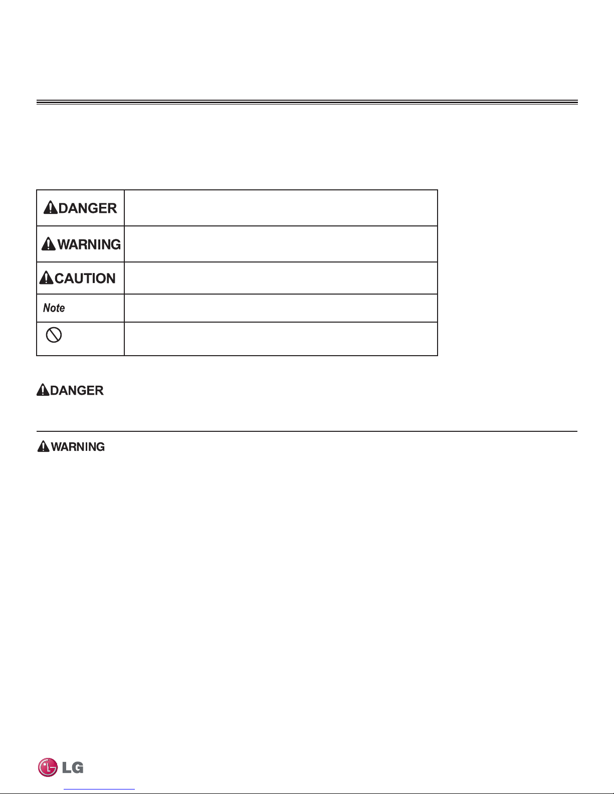
TABLE OF SYMBOLS
This symbol indicates an imminently hazardous situation which, if not avoided, will result in death or serious
injury.
This symbol indicates a potentially hazardous situation which, if not avoided, could result in death or serious
injury.
This symbol indicates a potentially hazardous situation which, if not avoided, may result in minor or
moderate injury.
This symbol Indicates situations that may result in equipment or property damage accidents only.
This symbol indicates an action should not be completed.
INSTALLATION
Don’t store or use ammable gas / combustibles near the unit.
There is risk of product failure, re, explosion, and physical injury or death.
Do not install, remove, or re-install the unit by yourself
(customer). Ask the dealer or an authorized technician to
install the unit.
Improper installation by the user may result in water leakage, re,
explosion, electric shock, physical injury or death.
For replacement of an installed unit, always contact an
authorized LG service provider.
There is risk of re, electric shock, explosion, and physical injury or death.
The unit is shipped with refrigerant and the service valves
are closed. Do not open service valves on the unit until all
condensation has been removed from the piping system and
authorization to do so has been obtained from the commissioning agent.
There is a risk of equipment damage, refrigerant contamination, refrigerant loss, physical injury or death.
Dispose the packing materials safely.
• Tear apart and throw away plastic packaging bags so that children do
not play with them and risk suffocation.
Wear protective gloves when handling equipment. Sharp
edges may cause physical injury.
The unit is shipped with refrigerant and service valves
closed. Do not run the compressor with the service valves
closed.
There is a risk of equipment damage, explosion, physical injury, or death.
Safety Instructions
Dispose the packing materials safely.
• Packing materials, such as nails and other metal or wooden parts,
may cause puncture wounds or other injuries.
• Ensure no metal scraps, screws, or bits of wiring are left inside or
surrounding the unit. There is a risk of physical injury.
Install the unit considering the potential for strong winds or
earthquakes.
Improper installation may cause the unit to fall over, resulting in physical
injury or death.
If the air conditioner is installed in a small space, take
measures to prevent the refrigerant concentration from
exceeding safety limits in the event of a refrigerant leak.
Consult the latest edition of ASHRAE (American Society of Heating,
Refrigerating, and Air Conditioning Engineers) Standard 15. If the
refrigerant leaks and safety limits are exceeded, it could result in personal
injuries or death from oxygen depletion.
Install the unit in a safe location where nobody can step on or
fall onto it.
There is risk of unit damage, physical injury or death.
Do not install the unit on a defective stand.
There is a risk of property damage or physical injury.
Due to our policy of continuous product innovation, some specifications may change without notification.
©LG Electronics U.S.A., Inc., Englewood Cliffs, NJ. All rights reserved. “LG” is a registered trademark of LG Corp.
3
SAFETY INSTRUCTIONS
INSTALLATION - CONTINUED
Periodically check that the outdoor frame is not damaged.
There is a risk of equipment damage, explosion, physical injury, or death.
Do not change the settings of the protection devices.
If the pressure switch, thermal switch, or other protection device is
shorted and forced to operate improperly, or parts other than those
specied by LG are used, there is risk of re, electric shock, explosion,
and physical injury or death.
Be very careful when transporting the product.
• Do not attempt to carry the product without assistance in order to
avoid physical injury.
• Some products use polypropylene bands for packaging. Do not use
polypropylene bands to lift the unit. Lifting the unit might cause physical injury.
• Suspend the unit from the base at specified positions to avoid property damage or physical injury .
Don’t install the unit where it’s directly exposed to ocean winds.
Ocean winds may cause corrosion, particularly on the condenser and
evaporator ns, which, in turn could cause product malfunction or inefcient performance.
When installing the unit in a low-lying area, or a location that
is not level, use a raised concrete pad or concrete blocks to
provide a solid, level foundation.
This may prevent water damage and reduce abnormal vibration.
Properly insulate all cold surfaces to prevent “sweating.”
Cold surfaces such as uninsulated piping can generate condensate that
may drip and cause a slippery oor condition and/or water damage to
walls.
When installing the unit in a hospital, mechanical room, or
similar electromagnetic eld (EMF) sensitive environment,
provide sufcient protection against electrical noise.
Inverter equipment, power generators, high-frequency medical equip-
Single Zone Art Cool Gallery Wall Mounted Installation Manual
ment, or radio communication equipment may cause the air conditioner to
operate improperly. The unit may also affect such equipment by creating
electrical noise that disturbs medical treatment or image broadcasting.
Replace all control box and panel covers.
If cover panels are not installed securely, dust, water and animals may
enter the water source unit, causing re or equipment malfunction.
Always check for system refrigerant leaks after the unit has
been installed or serviced.
Low refrigerant levels may cause product failure, and exposure to high
concentration levels of refrigerant gas may lead to illness or death. Keep
the unit upright during installation to avoid vibration or water leakage.
• Support the unit a minimum of four points to avoid slippage from
rigging apparatus which may result in physical injury.
Install the drain hose to ensure adequate drainage.
There is a risk of water leakage and property damage.
Do not use the product for special purposes such as
preserving foods, works of art, wine coolers, or other
precision air conditioning applications. The equipment is
designed to provide comfort cooling and heating.
There is risk of property damage.
Do not make refrigerant substitutions. Use R410A only.
If a different refrigerant is used, or air mixes with original refrigerant, the
unit will malfunction and be damaged.
When connecting refrigerant tubing, remember to allow for
pipe expansion.
Improper piping may cause refrigerant leaks and system malfunction.
Do not install the unit in a noise sensitive area.
Take appropriate actions at the end of HVAC equipment life
to recover, recycle, reclaim or destroy R410A refrigerant
according to applicable U.S. Environmental Protection
Agency (EPA) rules.
Due to our policy of continuous product innovation, some specifications may change without notification.
4
©LG Electronics U.S.A., Inc., Englewood Cliffs, NJ. All rights reserved. “LG” is a registered trademark of LG Corp.
WIRING
SAFETY INSTRUCTIONS
High voltage electricity is required to operate this system.
Adhere to the National Electrical Codes and these
instructions when wiring.
Improper connections and inadequate grounding can cause accidental
injury or death.
Always ground the unit following local, state, and National
Electrical Codes.
The information contained in this manual is intended for use
by an industry-qualied, experienced, certied electrician
familiar with the U.S. National Electric Code (NEC) who is
equipped with the proper tools and test instruments.
Failure to carefully read and follow all instructions in this manual can
result in equipment malfunction, property damage, personal injury or death.
All electric work must be performed by a licensed electrician
and conform to local building codes or, in the absence of
local codes, with the National Electrical Code, and the
instructions given in this manual.
If the power source capacity is inadequate or the electric work is not per-
formed properly, it may result in re, electric shock, physical injury or death.
Refer to local, state, and federal codes, and use power wires
of sufcient current capacity and rating.
Wires that are too small may generate heat and cause a re.
Turn the power off at the nearest disconnect before servicing
the equipment.
Electrical shock can cause physical injury or death.
Properly size all circuit breakers or fuses.
There is risk of re, electric shock, explosion, physical injury or death.
Secure all eld wiring connections with appropriate wire
strain relief.
Improperly securing wires will create undue stress on equipment power
lugs. Inadequate connections may generate heat, cause a re and physical injury or death.
Properly tighten all power lugs.
Loose wiring may overheat at connection points, causing a re, physical
injury or death.
Do not change the settings of the protection devices.
If the pressure switch, thermal switch, or other protection devices
are bypassed or forced to work improperly, or parts other than those
specied by LG are used, there is risk of re, electric shock, explosion,
and physical injury or death.
Do not supply power to the unit until all installation and precommissioning tasks are complete and the commissioning
agent indicates it is safe to do so.
Safety Instructions
OPERATION
Do not provide power to or operate the unit if it is ooded or
submerged.
There is risk of re, electric shock, physical injury or death.
Use a dedicated power source for this product.
There is risk of re, electric shock, physical injury or death.
Periodically verify the equipment mounts have not
deteriorated.
If the base collapses, the unit could fall and cause property damage,
product failure, physical injury or death.
If gas leaks out, ventilate the area before operating the unit.
Leaking gas may cause re, electric shock, explosion, physical injury or
death if the unit is mounted in an enclosed, low-lying, or poorly ventilated
area and the system develops a refrigerant leak.
Do not allow water, dirt, or animals to enter the unit.
• There is risk of unit failure or fire.
• Handling of the unit while wet can cause electric shock, physical
injury or death.
• Animals entering the unit can cause unit failure or fire.
Due to our policy of continuous product innovation, some specifications may change without notification.
©LG Electronics U.S.A., Inc., Englewood Cliffs, NJ. All rights reserved. “LG” is a registered trademark of LG Corp.
Do not operate the disconnect switch with wet hands.
There is risk of re, electric shock, physical injury or death.
• Use caution when trying to remove any animals from the unit to avoid
personal physical injury.
Do not touch the refrigerant piping during or after operation.
It can cause burns or frostbite.
Do not operate the unit with the panel(s) or protective
cover(s) removed; keep ngers and clothing away from
moving parts.
The rotating, hot, cold, and high-voltage parts of the unit can cause
physical injury or death.
Periodically, check power cord and plug for damage.
Cord must be replaced by the manufacturer, its service agent, or similar
qualied persons in order to avoid physical injury and/or electric shock.
5
SAFETY INSTRUCTIONS
OPERATION - CONTINUED
- Continued
Do not open the inlet grille of the unit during operation. Do
not operate the unit with the panels or guards removed. Do
not insert hands or other objects through the inlet or outlet
when the unit is plugged in. Do not touch the electrostatic
lter, if the unit includes one.
The unit contains sharp, rotating, hot, and high voltage parts that can
cause personal injury and/or electric shock.
Clean up the site after installation is nished, and check that no metal scraps,
screws, or bits of wiring have been left inside or surrounding the unit.
Do not use this equipment in mission critical or specialpurpose applications such as preserving foods, works of art,
wine coolers or refrigeration. The equipment is designed to
provide comfort cooling and heating.
Oil, steam, sulfuric smoke, etc., can signicantly reduce the performance
of the unit, or damage its parts.
To avoid physical injury, use caution when cleaning or
servicing the air conditioner.
Provide power to the compressor crankcase heaters at least
six (6) hours before operation begins.
Starting operation with a cold compressor sump(s) may result in severe
bearing damage to the compressor(s). Keep the power switch on during
the operational season.
Do not block the inlet or outlet.
Unit may malfunction.
Securely attach the electrical part cover to the indoor unit
and the service panel to the outdoor unit.
Non-secured covers can result in re or electric shock due to dust or water.
Single Zone Art Cool Gallery Wall Mounted Installation Manual
Due to our policy of continuous product innovation, some specifications may change without notification.
6
©LG Electronics U.S.A., Inc., Englewood Cliffs, NJ. All rights reserved. “LG” is a registered trademark of LG Corp.

TABLE OF CONTENTS
General Data .......................................................................................... 8
Unit Nomenclature ............................................................................... 8
Art Cool Gallery Unit Specications ................................................... 10
Electrical .............................................................................................11
R410A Refrigerant ............................................................................. 12
General Installation Guidelines .......................................................... 13
Location Selection ............................................................................. 13
Oceanside Applications ..................................................................... 14
Mounting Bolt Location ...................................................................... 15
Required Clearances ......................................................................... 16
Mounting of Indoor Unit ................................................................ 17-19
Piping Preparation ............................................................................. 20
Piping Preparation/Piping Materials and Handling ....................... 21-26
Piping Support, Elbow Usage ............................................................ 27
Refrigerant Piping Connections ......................................................... 28
Refrigerant Piping System Layout ..................................................... 28
Refrigerant Piping System Limitations ............................................... 29
Installation Overview ......................................................................... 30
Directional Pipe Formation ................................................................ 31
Drain Hose ......................................................................................... 32
Outdoor Unit Connections ................................................................. 33
Indoor Unit Connections .................................................................... 34
Bundling and Cutting Line ................................................................. 35
Refrigerant Piping Insulation ........................................................ 36-37
Pipe Sleeves at Penetrations ............................................................ 38
Air Purging ......................................................................................... 39
Leak Test/Soap Method Check .......................................................... 40
Evacuation of Lines ........................................................................... 41
Finishing Up, Charging ...................................................................... 41
Front Panel Assembly/Test Run ......................................................... 42
Remote Controller ............................................................................. 43
Pump Down, Cooling Only Mode ...................................................... 44
Electrical Wiring .................................................................................. 46
General Information and Safety Guidelines ....................................... 46
Power Wiring Specications and Best Practices .......................... 47-48
Controllers ......................................................................................... 49
Indoor Unit Electrical Connections .................................................... 50
Outdoor Unit Electrical Connections .................................................. 51
Troubleshooting .................................................................................. 52
Self Diagnosis Functions ............................................................. 52-53
LG SIMS - Self Diagnosis Functions ........................................... 54-55
Error Codes ................................................................................. 56-58
Cautions for Refrigerant Leaks .......................................................... 59
Refrigerant Leaks .............................................................................. 59
Installation Checklist ........................................................................... 60
Due to our policy of continuous product innovation, some specifications may change without notification.
©LG Electronics U.S.A., Inc., Englewood Cliffs, NJ. All rights reserved. “LG” is a registered trademark of LG Corp.
7
GENERAL DATA
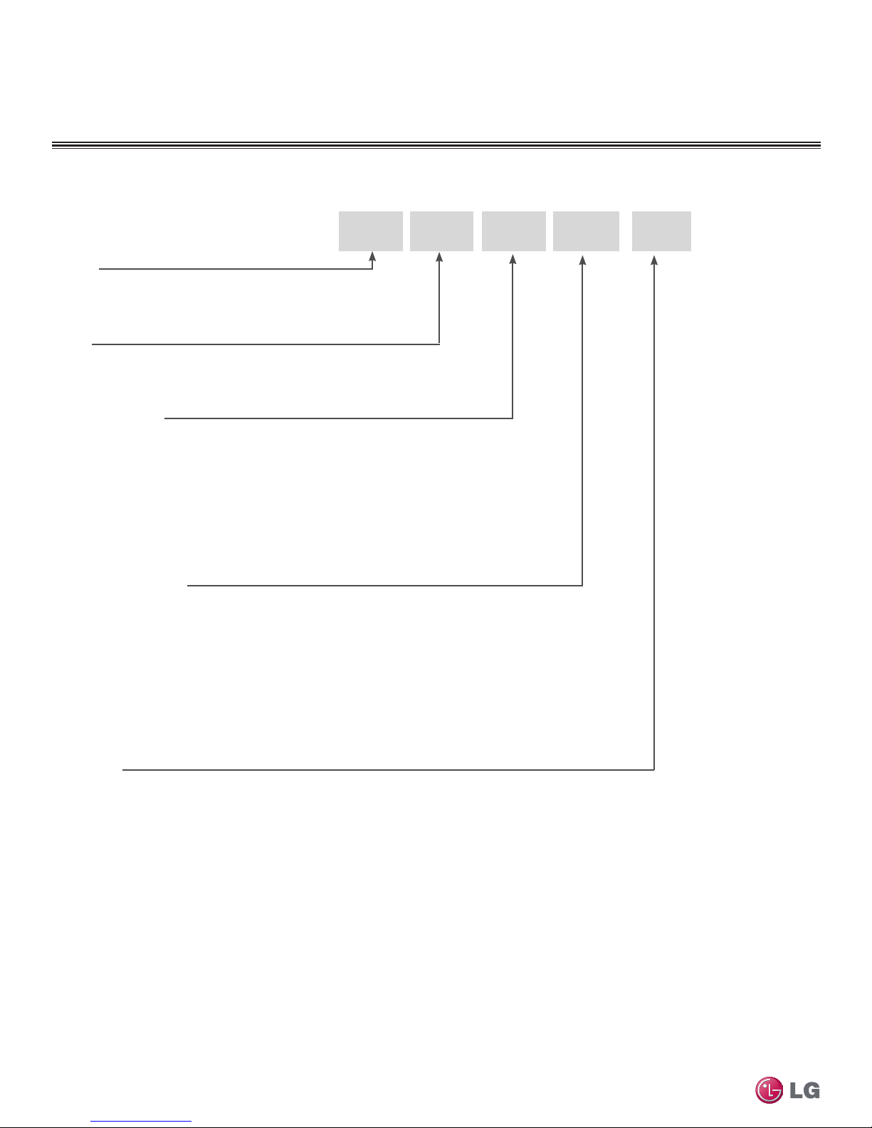
Unit Nomenclature
Single Zone Wall Mount Indoor and Outdoor Units
Family
LA= Art Cool Premier/Gallery/Mirror
LS= High Efficiency Wall Mount/Standard/ Mega
Type
N = Indoor Wall Mount Unit
U = Outdoor Heat Pump Unit
Nominal Capacity
(Nominal cooling capacity in Btu/h)
090/091 = 9,000
120/121 = 12,000
180/181 = 18,000
240 = 24,000
307 = 30,000
360 = 36,000
Indoor/Outdoor Product
HEV = Mega
HXV = Mega 115V
HYV = Art Cool Premier
HVP = Art Cool Gallery
HSV3 = High Efficiency
HSV2 = Art Cool Mirror
HV = Standard
HLV = Extended Pipe
Generation
2 = Second
3 = Third
LA
N 090 HVP 2
Single Zone Art Cool Gallery Wall Mounted Installation Manual
Due to our policy of continuous product innovation, some specifications may change without notification.
8
©LG Electronics U.S.A., Inc., Englewood Cliffs, NJ. All rights reserved. “LG” is a registered trademark of LG Corp.
GENERAL DATA
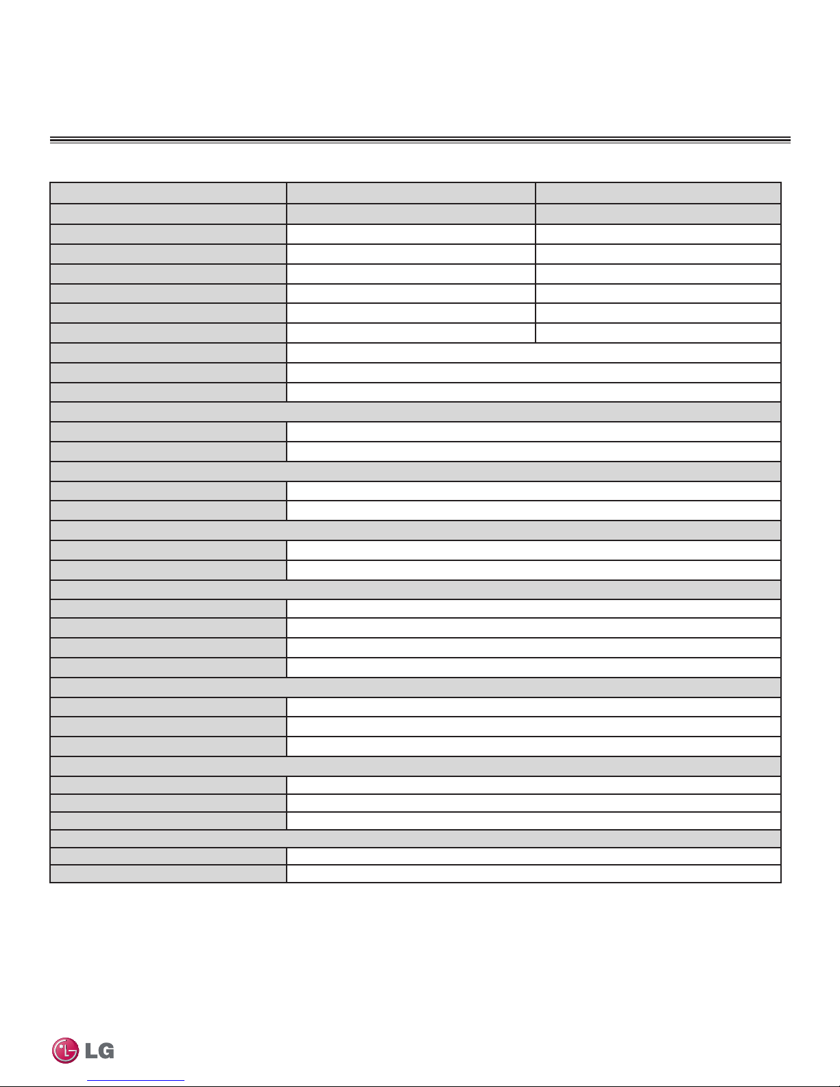
Art Cool Gallery Unit Specications
Table 1: Art Cool Gallery Unit Specications
Type Art Cool Gallery Art Cool Gallery
System (Model) LA090HVP (LAN090HVP/LAU090HVP) LA120HVP (LAN120HVP/LAU120HVP)
Nominal Cooling Capacity (Btu/h) 9,000 11,200
Cooling Power Input1 (kW) 0.72 0.93
Nominal Heating Capacity (Btu/h) 10,800 13,300
Heating Power Input1 (kW) 0.85 1.25
Cooling COP 3.66 3.52
EER 12.5 12
SEER 16
HSPF 8.2
Power Supply (V / Hz / Ø) 208-230/60/1
ODU Operating Range
Cooling (°F DB) 14-118
Heating (°F WB) 14-75
IDU Operating Range
Cooling (°F WB) 64-90
Heating (°F DB) 60-86
Indoor Temperature Setting Range
Cooling (°F) 65-86
Heating (°F) 61-86
Unit Data
Refrigerant Type2 R410A
Refrigerant Control EEV
IDU Sound Pressure3 dB(A) (H/M/L) 42/36/32
ODU Sound Pressure dB(A) 45
Unit Weight (lbs)
Indoor Unit (Net/Shipping) 31/34
Outdoor Unit (Net/Shipping) 78/82
Power/Communication Cable4 (No. x AWG) 4 x 18
Fan
Indoor Type (Qty) Turbo (1)
Outdoor Type (Qty) Propeller (1)
Motor/Drive Brushless Digitally Controlled/Direct
Airflow Rate
Indoor - Max/H/M/L (CFM) 370/335/311/247
Outdoor - Max (CFM) 1,165
EEV: Electronic Expansion Valve IDU: Indoor Unit ODU: Outdoor Unit
Power wiring is field supplied and must comply with the applicable local and national codes.
This unit comes with a dry helium charge.
This data is rated 0 ft above sea level, with 24.6 ft of refrigerant line per indoor unit and a 0 ft level
difference between outdoor and indoor units.
Cooling capacity rating obtained with air entering the indoor coil at 80ºF dry bulb (DB) and 67ºF wet
bulb (WB); and outdoor ambient conditions of 95ºF dry bulb (DB) and 75ºF wet bulb (WB).
Heating capacity rating obtained with air entering the indoor unit at 70ºF dry bulb (DB) and 60ºF wet
bulb (WB); and outdoor ambient conditions of 47ºF dry bulb (DB) and 43ºF wet bulb (WB).
1
Power Input is rated at high speed.
2
Take appropriate actions at the end of HVAC equipment life to recover, recycle, reclaim or destroy
R410A refrigerant according to applicable regulations (40 CFR Part 82, Subpart F) under section 608
of CAA.
3
Sound Pressure levels are tested in an anechoic chamber under ISO Standard 1996.
4
All power/communication cables to be minimum 18 AWG, 4-conductor, stranded, shielded and must
comply with applicable and national code.
Product Data
Due to our policy of continuous product innovation, some specifications may change without notification.
©LG Electronics U.S.A., Inc., Englewood Cliffs, NJ. All rights reserved. “LG” is a registered trademark of LG Corp.
9
GENERAL DATA
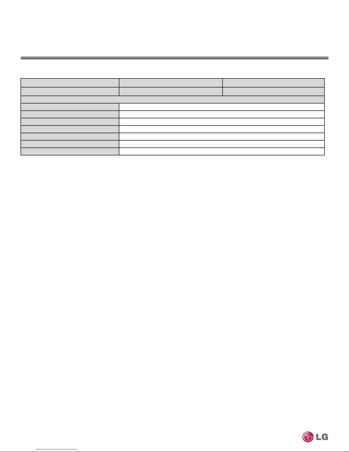
Art Cool Gallery Unit Specications
Table 1: Art Cool Gallery Unit Specications - Continued
Type Art Cool Gallery Art Cool Gallery
System (Model) LA090HVP (LAN090HVP/LAU090HVP) LA120HVP (LAN120HVP/LAU120HVP)
Piping
Liquid Line (in, OD) 1/4
Vapor Line (in, OD) 3/8
Condensation Line (OD | ID) 27/32 | 5/8
Additional Refrigerant Charge (oz/ft) 0.22
Pipe Length (Min/Max) (ft)
Piping Length (no add’l refrigerant, ft)
Max Elevation Difference (ft) 22.9
EEV: Electronic Expansion Valve IDU: Indoor Unit ODU: Outdoor Unit
Power wiring is field supplied and must comply with the applicable local and national codes.
This unit comes with a dry helium charge.
This data is rated 0 ft above sea level, with 24.6 ft of refrigerant line per indoor unit and a 0 ft level
difference between outdoor and indoor units.
5
5
Cooling capacity rating obtained with air entering the indoor coil at 80ºF dry bulb (DB) and 67ºF wet
bulb (WB); and outdoor ambient conditions of 95ºF dry bulb (DB) and 75ºF wet bulb (WB).
Heating capacity rating obtained with air entering the indoor unit at 70ºF dry bulb (DB) and 60ºF wet
bulb (WB); and outdoor ambient conditions of 47ºF dry bulb (DB) and 43ºF wet bulb (WB).
5
Piping lengths are equivalent.
9.8/49.2
24.6
Single Zone Art Cool Gallery Wall Mounted Installation Manual
Due to our policy of continuous product innovation, some specifications may change without notification.
10
©LG Electronics U.S.A., Inc., Englewood Cliffs, NJ. All rights reserved. “LG” is a registered trademark of LG Corp.
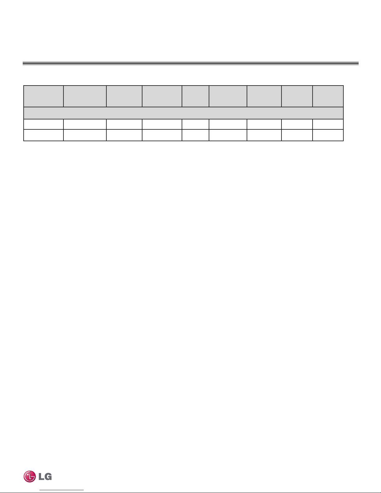
Table 2: Art Cool Gallery Indoor Unit Electrical Data
GENERAL DATA
Electrical
Unit Model Nos.
Nom.
Tons
Compressor
Qty
Compressor(A)
Cool/Heat
Fan Qty ODU Fan(A) IDU Fan(A) MCA(A) MOP(A)
Art Cool Premier
LAU090HVP
3/4 1 6.8/7.6 1 0.25 14.7 10 15
LAU120HVP 1 1 6.8/7.6 1 0.25 14.7 10 15
For component model nos.
Voltage tolerance is ±10%.
Maximum allowable voltage unbalance is 2%.
MCA = Minimum Circuit Ampacity
ODU Fan = Outdoor Unit Fan Motor
IDU Fan = Indoor Unit Fan Motor
Maximum Overcurrent Protection (MOP) is calculated as follows:
(Largest motor FLA x 2.25) + (Sum of other motor FLA) rounded down
to the nearest standard fuse size.
Product Data
Due to our policy of continuous product innovation, some specifications may change without notification.
©LG Electronics U.S.A., Inc., Englewood Cliffs, NJ. All rights reserved. “LG” is a registered trademark of LG Corp.
11
GENERAL DATA
R410A Refrigerant
R410A Refrigerant - 0% Ozone Depleting
R410A refrigerant has a higher operating pressure in comparison to R22 refrigerant and, therefore, all piping system materials installed must
have a higher resisting pressure than the materials traditionally used in R22 systems.
R410A refrigerant is an azeotrope of R32 and R125, mixed at 50:50, so the ozone depletion potential (ODP) is 0.
• To prevent the refrigerant cylinder from exploding, do not place it in direct sunlight.
• Do not use any piping that has not been approved for use in high-pressure refrigerant systems.
• To prevent the piping from softening, do not heat it more than necessary during installation.
• Piping wall thickness must comply with the applicable local, state, and federal codes for the 551 psi design pressure of R410A.
• Because R410A is a combination of R32 and R125, the required additional refrigerant must be charged in its liquid state. If the refrig-
erant is charged in its gaseous state, its composition changes and the system will not work properly.
Single Zone Art Cool Gallery Wall Mounted Installation Manual
Due to our policy of continuous product innovation, some specifications may change without notification.
12
©LG Electronics U.S.A., Inc., Englewood Cliffs, NJ. All rights reserved. “LG” is a registered trademark of LG Corp.
GENERAL INSTALLATION GUIDELINES
DANGER
Location Selection
Selecting the Best Location
To avoid the possibility of re, do not install the unit in an area where combustible gas may generate, ow, stagnate, or leak. Failure to do so can cause
serious bodily injury or death.
• Install a fence to prevent vermin from crawling into the unit or unauthorized individuals from accessing it.
• Do not install the unit in a location where acidic solution and spray (sulfur) are often used as this may cause serious bodily injury or death.
• Do not use the unit in environments where oil, steam, or sulfuric gas are present as this may cause serious bodily injury or death.
Select a location for installing the outdoor unit that will meet the following conditions:
• Where the unit will not be subjected to direct thermal radiation from other heat sources.
• Where operating sound from the unit will not disturb inhabitants of surrounding buildings.
• Where the unit will not be exposed to direct, strong winds.
• Where there is enough strength to bear the weight of the unit.
• Include space for drainage to ensure condensate flows properly out of the unit when it is in heating mode.
• Include enough space for air flow and for service access.
General Installation Guidelines
To ensure the outdoor unit operates properly, certain measures are required in locations where there is a possibility of heavy snowfall or
severe wind chill or cold:
1. Prepare for severe winter wind chills and heavy snowfall, even in areas of the country where these are unusual phenomena.
2. Position the outdoor unit so that its airflow fans are not buried by direct, heavy snowfall. If snow piles up and blocks the airflow, the
system may malfunction.
3. Remove any snow that has accumulated by 4 inches or more on the top of the outdoor unit.
4. Place the outdoor unit on a raised platform at least 20 inches higher than the average annual snowfall for the area. In environments where
there is a possibility of heavy snow, the frame height must be more than two (2) times the amount of average annual snowfall, and should
not exceed the width of the outdoor unit. If the frame width is wider than the outdoor unit, snow may accumulate.
5. Install a snow protection hood.
6. To prevent snow and heavy rain from entering the outdoor unit, install the suction and discharge ducts facing away from direct winds.
7. Additionally, the following conditions should be taken into consideration when the unit operates in defrost mode:
• If the outdoor unit is installed in a highly humid environment (near an ocean, lake, etc.), ensure that the site is well-ventilated and has a lot
of natural light. (Example: Install on a rooftop.)
• Sidewalks or parking lots near the outdoor unit may accumulate moisture after unit operates in defrost mode that can turn to ice.
The indoor unit may take longer to provide heat, or heating performance will be reduced in winter if the unit is installed:
1. In a narrow, shady location.
2. Near a location that has a lot of ground moisture.
3. In a highly humid environment.
4. In an area in which condensate does not drain properly.
Ambient Air Conditions
• Avoid exposing the unit to discharge from boiler stacks, chimneys, steam relief ports, other air conditioning units, kitchen vents, plumbing
vents, or substances that may degrade performance or cause damage to the unit.
• When installing multiple outdoor units, avoid placing the units where discharge of one outdoor unit will blow into the inlet side of an adja-
cent unit.
Avoid exposing the unit to sources of extreme temperature or gases to prevent serious bodily injury.
Due to our policy of continuous product innovation, some specifications may change without notification.
©LG Electronics U.S.A., Inc., Englewood Cliffs, NJ. All rights reserved. “LG” is a registered trademark of LG Corp.
13
GENERAL INSTALLATION GUIDELINES
Oceanside Applications
Oceanside Applications
Use of a Windbreak to Shield from Sea Wind
Ocean winds may cause corrosion, particularly on the condenser and
evaporator ns, which, in turn could cause product malfunction or
inefcient performance.
• The unit should be installed in a soundproofed mechanical room.
• Avoid installing the outdoor unit where it would be directly exposed
to ocean winds.
• Install the outdoor unit on the side of the building opposite from
direct ocean winds.
• Select a location with good drainage.
• Periodically clean dust or salt particles off of the heat exchanger
with fresh water.
• If the outdoor unit must be placed in a location where it would
be subjected to direct ocean winds, install a concrete windbreak
strong enough to block any winds.
• Windbreak should be more than 150% of the outdoor unit’s height.
There must be 2ft and 3 1/2 inches clearance between the outdoor
unit and the windbreaker for purposes of air flow.
Figure 1: Oceanside Placement Using Windbreak
Windbreak
Sea wind
Additional anti-corrosion treatment may need to be applied to the
outdoor unit at oceanside locations.
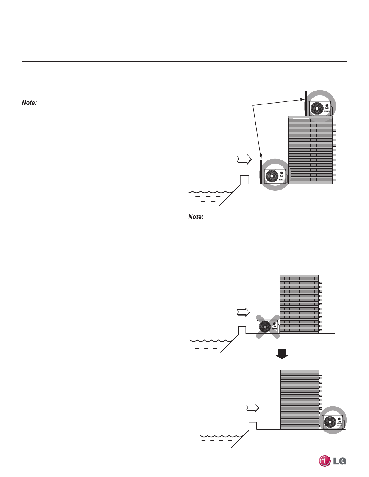
Oceanside Applications
Use of a Building to Shield from Sea Wind
If a windbreak is not possible, a building or larger structure must
be used to shield the outdoor unit from direct exposure to the sea
wind. The unit should be placed on the side of the building directly
opposite to the direction of the wind as shown in Figure 2.
Single Zone Art Cool Gallery Wall Mounted Installation Manual
Figure 2: Placement Using Building as Shield
Building
Sea wind
Building
Sea wind
Due to our policy of continuous product innovation, some specifications may change without notification.
14
©LG Electronics U.S.A., Inc., Englewood Cliffs, NJ. All rights reserved. “LG” is a registered trademark of LG Corp.
GENERAL INSTALLATION GUIDELINES
Bolt
Placement
& Anti-Vibration
Pad
Piping Connection
Top of Unit
Foundation
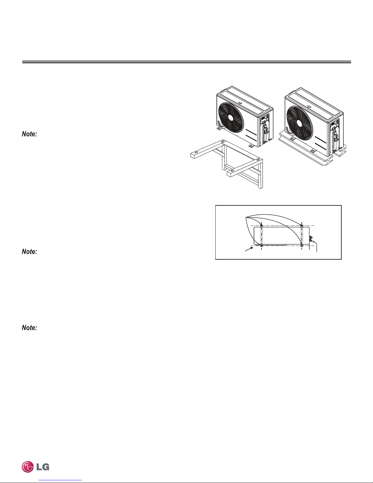
Mounting Bolt Location
General Mounting
Securely attach the outdoor unit to a condenser pad, base rails, or
another mounting platform that is securely anchored to the ground
or building structure. Attach the outdoor unit with a bolt and nut on a
concrete or rigid mount. See Figure 3. Follow applicable local codes
for clearance, mounting, anchor and vibration attenuation requirements.
All referenced materials are to be eld-supplied. Images are not to scale.
Mounting Platform
The underlying structure or foundation must be designed to support
the weight of the unit. Avoid placing the unit in a low lying area
where water may accumulate. When installing the outdoor unit on
the wall, or roof top, anchor the mounting base securely to account
for wind, earthquake or vibration.
Tie-Downs and Wind Restraints
The strength of the Duct-free Split Single Zone Inverter system
frame is adequate to be used with field-provided wind restraint tiedowns. The overall tie-down configuration must be approved by a
local professional engineer.
Figure 3: Outdoor Unit Mounting Methods
General Installation Guidelines
Always refer to local code when designing a wind restraint system.
Snow and Ice Conditions
In climates that experience snow build-up, place the unit on a raised platform to ensure condenser airflow. The raised support platform must
be high enough to allow the unit to remain above possible snow drifts. Mount the unit on a field-provided snow stand at a minimum height
that is equal to the average annual snowfall plus 20 inches. Design the mounting base to prevent snow accumulation on the platform in front
or back of the unit case. If necessary, provide a field fabricated hood to keep snow and ice and/or drifting snow from accumulating on the coil
surfaces. Use inlet and discharge duct or hoods to prevent snow or rain from accumulating on the fan inlet and outlet guards. Best practice
prevents snow from accumulating on top of the unit. Consider tie-down requirements in case of high winds or where required by local codes.
When deciding on a location to place the outdoor unit, be sure to choose an area where run-off from defrost will not accumulate and freeze on
sidewalks or driveways.
Due to our policy of continuous product innovation, some specifications may change without notification.
©LG Electronics U.S.A., Inc., Englewood Cliffs, NJ. All rights reserved. “LG” is a registered trademark of LG Corp.
15
GENERAL INSTALLATION GUIDELINES
Outdoor Unit Clearance
12
28
24
12
24
Unit : inch
More than
12
More than
12
Sunroof
Fence or
obstacles
More than
28
Unit : inch
More than
24
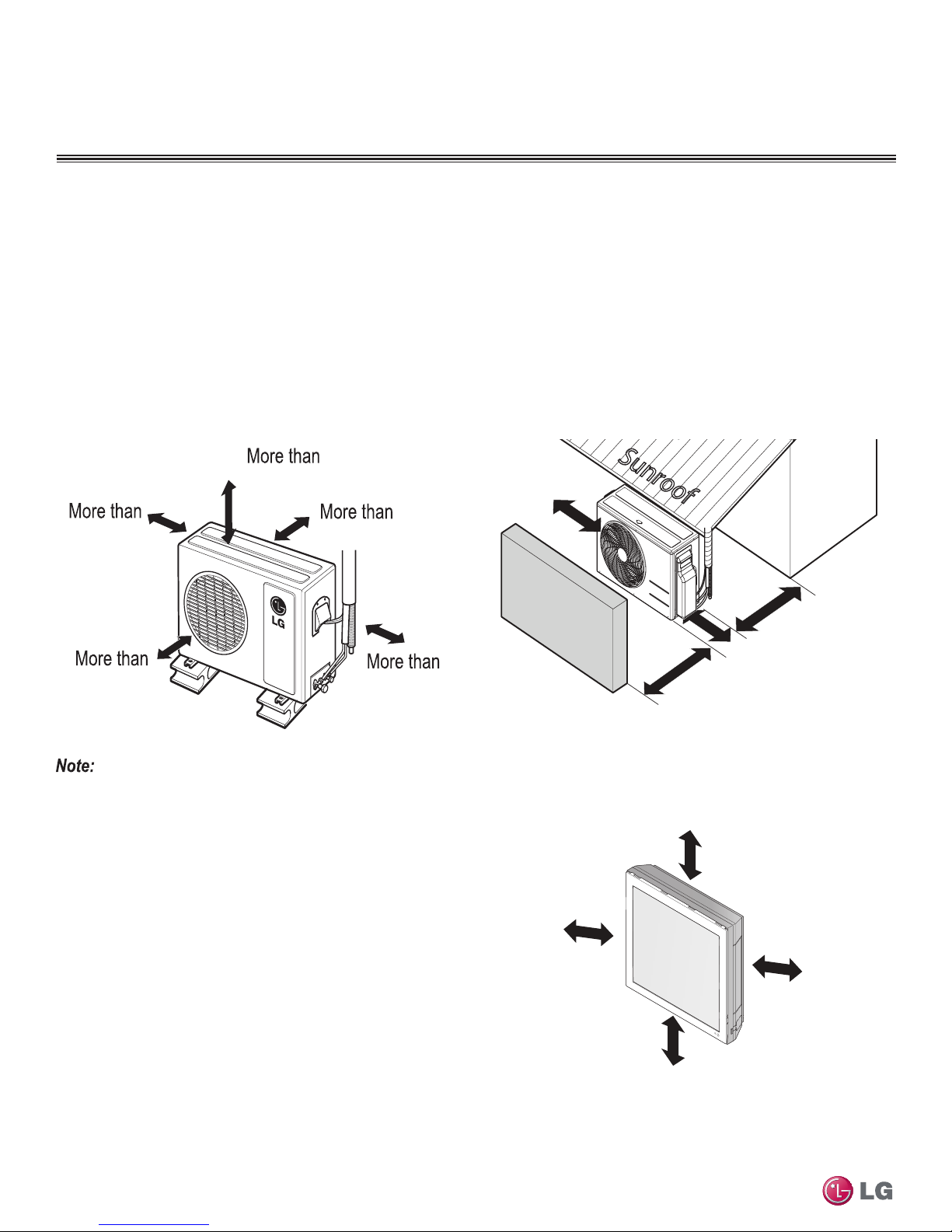
Required Clearances
Proper airflow through the Single Zone outdoor unit coil is critical for correct unit operation. When installing, consider service, inlet and outlet,
and minimum allowable space requirements as illustrated in the diagrams below.
Minimum Clearance Requirements for Single Zone Wall Mount
Outdoor Unit Clearance
Specific clearance requirements in the diagram below are for the single zone wall mount systems. Figure 4 shows the overall minimum
clearances that must be observed for safe operation and adequate airflow around the outdoor unit.
When placing the outdoor unit under an overhang, awning, sunroof or other roof-like structure, observe the clearance requirements (as shown in
Figure 5) for height in relation to the unit. This clearance ensures that heat radiation from the condenser is not restricted around the unit.
Adhere to all clearance requirements if installing the unit on a roof. Be sure to level the unit and ensure that the unit is adequately anchored.
Consult local codes for rooftop mounting requirements.
Figure 4: Outdoor Unit Clearances
Figure 5: Outdoor Unit Sunroof/Awning Clearances
Do not place the unit where animals and/or plants will be in the path of the warm air, or where the warm air and/or noise will disturb neighbors.
Indoor Unit Clearance
Follow recommended best practices when choosing an indoor
location for the Single Zone indoor unit to avoid malfunctioning of
the unit.
• Keep unit away from any indoor steam or excessive heat.
Single Zone Art Cool Gallery Wall Mounted Installation Manual
• No obstacles should be placed around unit.
• Condensation drain (Leakage piping) should be routed away from
the unit.
• Do not install near doorway.
• Clearance gap between any wall or enclosure and the left or right
side of the unit must be greater than 20 inches.
• From the top of the unit to the ceiling there must be greater than 8
inches of clearance.
• Unit should be at least 8 feet from the oor for adequate clearance.
16
Due to our policy of continuous product innovation, some specifications may change without notification.
©LG Electronics U.S.A., Inc., Englewood Cliffs, NJ. All rights reserved. “LG” is a registered trademark of LG Corp.
More than
20 inches
94
1/2
inches
More than
8 inches
More than
20 inchesMore than
GENERAL INSTALLATION GUIDELINES
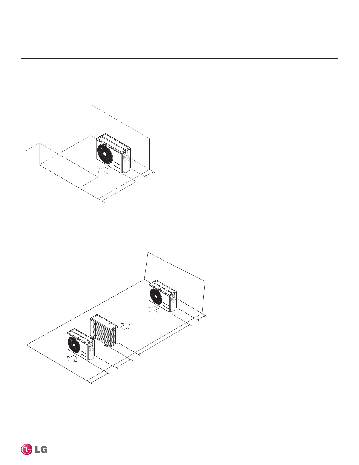
Required Clearances
Minimum Clearance Requirements for Single Zone Wall Mount - Continued
Figure 6: ODU Service Access Clearance - Single Unit
ODU Service Access & Clearances
Unit: Inch
Minimum
27-19/32
Figure 7: ODU Service Access Clearance - Multiple Units
In order to have successful service access to the out door unit,
see Figure 8 for minimum spacing.
When installing multiple outdoor units, see Figure 9 for correct
spacing requirements.
General Installation Guidelines
Minimum
11-13/16
Multiple ODUs
Service Access & Clearances
23-19/32
Minimum
78-3/4
Unit: Inch
Minimum
11-13/16
Due to our policy of continuous product innovation, some specifications may change without notification.
©LG Electronics U.S.A., Inc., Englewood Cliffs, NJ. All rights reserved. “LG” is a registered trademark of LG Corp.
17
GENERAL INSTALLATION GUIDELINES
Panel Front
Connector
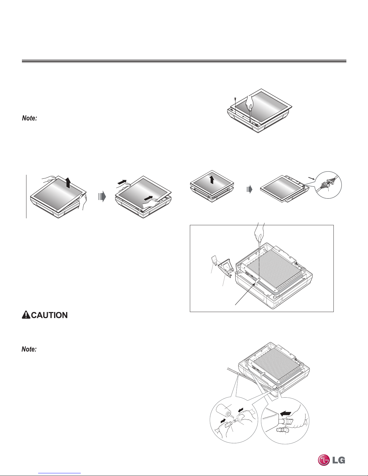
Mounting of Indoor Unit
Detaching Front Panel from Indoor Unit
Before you can mount the indoor unit to the wall, you must remove
the front cover. Removal will allow you to knock out any side holes
for the drain hose, as well as allow you to mount the unit without
damaging the front cover.
It is recommended that the front panel not be re-attached to the indoor
unit until the nal test has been run which will ensure that all electrical and
piping connections are working properly.
Procedure
1. Lay the indoor unit on a flat surface, and then pull the upper part
of the front panel away from the body.
2. Lift up the front panel so that the bottom part of the unit is visible.
3. Detach the front cover, by removing the two screws.
4. Remove the front cover away from the body, and be sure to
disconnect the front panel connector as shown below.
Disconnect
Removing Side Bottom Covers and Piping Hole Knockout
Before mounting the indoor unit, you may need to remove either the
right or left bottom side covers and the piping hole knockout, in order
to pass the drain hose and piping through. This procedure should be
done after removal of the front panel of the indoor unit.
Procedure
1. Using a phillips head screwdriver, remove the center bottom
screw from the L-bracket tube holder (Figure 8).
2. Detach one of the side covers (either right or left depending on
how you want to place the piping and drain hose).
3. Knockout the piping hole from the detached side cover.
After knocking out the piping hole from the side cover, be sure to smooth
or cut any burrs around the hole. Burrs left on can lead to physical cuts
and scrapes.
Single Zone Art Cool Gallery Wall Mounted Installation Manual
If you are planning to create a piping hole directly through the rear wall
you might not need to knockout the piping hole from the side cover.
Preparing for Piping Connection
1. To prepare indoor unit for piping, remove the rubber plugs at the
desired drain direction (left or right at bottom of the unit) (Figure 9).
• Be sure that the drain hose is routed to the closest pipe hole under
the unit.
2. Insert the drain hose into the opening/handle of the drain pan, and
then attach the drain hose and connecting hose using recommended adhesive.
• Step 2 can be done once the indoor unit is mounted to the wall if
necessary.
Figure 8: IDU - Removal of L-bracket and Side Cover
Pipe hole
knockout
Detach side
cover
L-bracket holder
For piping
Figure 9: IDU - Attaching Drain Hose
Adhesive
Drain
hose
Connecting
part
Drain hose
Only th e
desired directio n
desired direction
rubber cap
Due to our policy of continuous product innovation, some specifications may change without notification.
18
©LG Electronics U.S.A., Inc., Englewood Cliffs, NJ. All rights reserved. “LG” is a registered trademark of LG Corp.
GENERAL INSTALLATION GUIDELINES
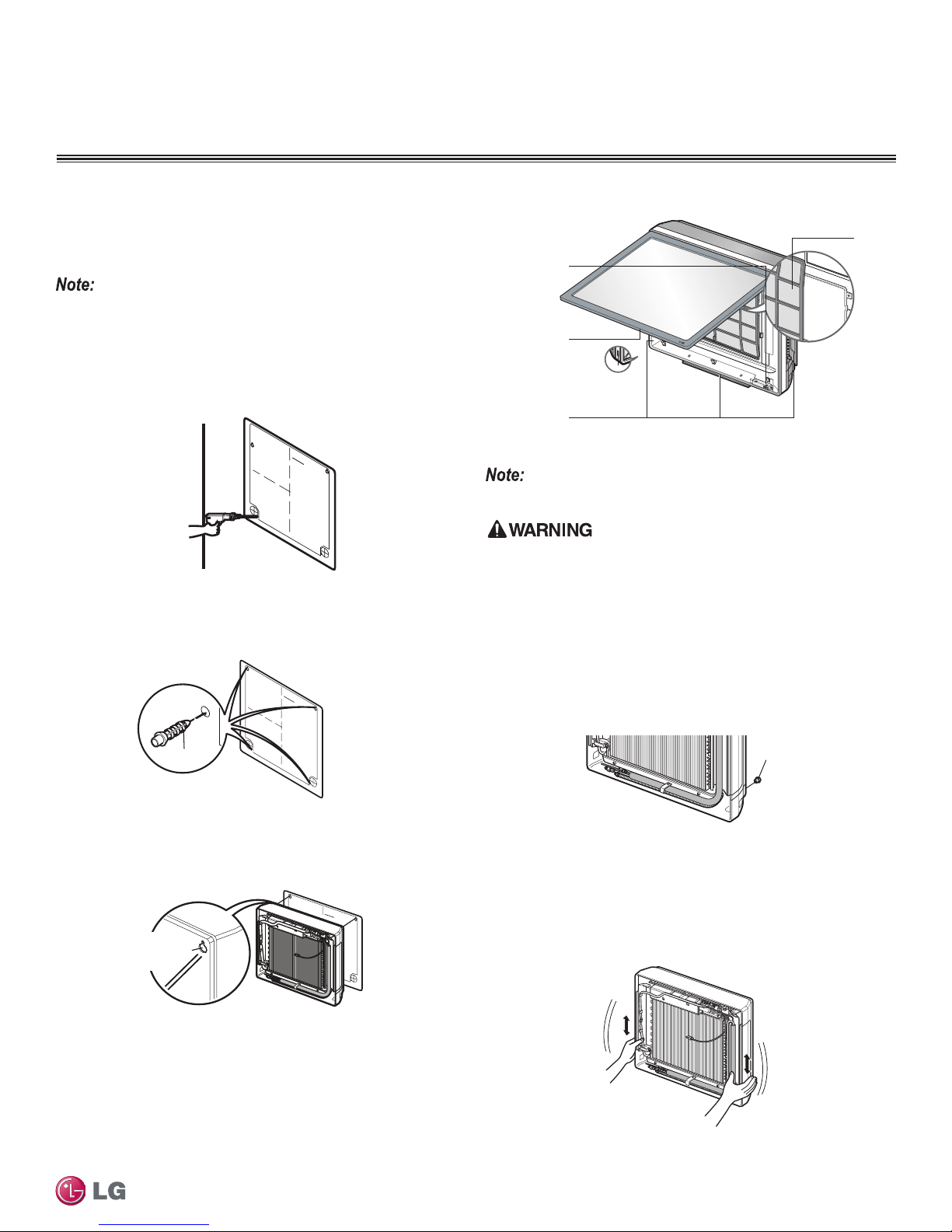
Mounting of Indoor Unit
Mounting Indoor Unit
Refer to Figure 10 as you mount the indoor unit.
Procedure
1. Using the supplied mounting template, align and level the template onto the wall.
Be careful to not discard or accidentally throw out the mounting template
that comes with the unit. This template assures accurate measurements
when drilling the holes for attaching screws.
2. Lightly attach the guide using adhesive tape.
3. Using a drill, create four 1/4 inch holes which are approximately 1
1/4 inch deep at the drill and cross marks on the mounting guide.
4. Using the four plastic anchors, drive each one into each of the
drilled holes.
INST AIIA TION GUIDE MA
INST
ALLA
TION GUIDE MAP
P
Figure 10: Gallery Indoor Unit Components
Air Filter
Signal Receptor
Front Panel
ON/OFF butto n
Air Discharge
General Installation Guidelines
Select location carefully. Unit should be anchored to a strong wall to prevent unnecessary vibration.
• When choosing a location for the wall mount plate, be sure to take
into consideration routing of wiring for power outlets within the wall.
Contacting wiring can cause serious bodily injury or death.
• Use caution when drilling holes through the walls for the purposes
of piping connections. Power wiring can cause serious bodily injury
or death.
6. Once the top is attached, anchor the bottom of the Gallery unit
using the plastic anchors and screws. Also leave about 1/3 inch
of the screw out of the wall to hang the unit.
Plastic anchors
5. Insert screws into the top left and right of the guide and leave
about 1/3 inch of the screw out of the wall.
• This will allow enough room to hang the Gallery unit.
INST
ALLA
TION GUIDE MAP
Hanger hole
(Rear side of
the product)
Due to our policy of continuous product innovation, some specifications may change without notification.
©LG Electronics U.S.A., Inc., Englewood Cliffs, NJ. All rights reserved. “LG” is a registered trademark of LG Corp.
Plastic anchors
7. Once unit is anchored, test by gently applying downward
pressure with both hands and jiggling to be sure it is securely
attached.
• If it is loose in anyway, retrace the above steps and adjust any of
the screws as needed.
19
 Loading...