

LG TWC051HGAA2.AWYBLAT (W051CA), TWC061HGAA2.AWYBLAT, TWC062HGAA0.AWYBLCP, TWC052HGAA0.AWYBLCP, W051CA Service Manual
...
LG
Room
Air Conditioner
SERVICE MANUAL
LG
MODEL: TWC051HGAA2.AWYBLAT (W051CA)
TWC052HGAA0.AWYBLCP (LA050MG)
TWC061HGAA2.AWYBLAT (W061CA)
TWC062HGAA0.AWYBLCP (LA060MG1)
CAUTION
• BEFORE SERVICING THE UNIT, READ THE SAFETY
PRECAUTIONS IN THIS MANUAL.
• ONLY FOR AUTHORIZED SERVICE PERSONNEL.
website http://www.lgservice.com

2 Room Air Conditioner
Air Conditioner Service Manual
TABLE OF CONTENTS
Safety Precautions..........................................................................................................................................3
Dimensions .....................................................................................................................................................5
Outside Dimensions..............................................................................................................
.....................5
Product Specifications ...............................................................................................................................
...
6
Installation ...............................................................................................................................
........................
7
Select the Best Location ..........................................................................................................
.................7
How to Install...................................................................................................................
...........................7
Operation ........................................................................................................................................................8
Features .....................................................................................................................................................8
Insulation Resistance Test..........................................................................................................................8
About the Controls on the Air conditioner ..................................................................................................8
Disassembly ....................................................................................................................................................9
Mechanical Parts........................................................................................................................................9
Air Handling Parts ....................................................................................................................................10
Electrical Parts .........................................................................................................................................11
Refrigerating Cycle...................................................................................................................................12
Schematic Diagram.......................................................................................................................................15
Wiring Diagram.........................................................................................................................................15
Troubleshooting Guide.................................................................................................................................16
Piping System ..........................................................................................................................................16
Troubleshooting Guide .............................................................................................................................17
Room Air Conditioner Voltage Limits........................................................................................................19
Exploded View ..............................................................................................................................................22
Replacement Parts List ................................................................................................................................23
Service Manual 3
Safety Precautions
Safety Precautions
To prevent injury to the user or other people and property damage, the following instructions must
be followed.
■ Incorrect operation due to ignoring instruction will cause harm or damage. The seriousness is
classified by the following indications.
■ Meanings of symbols used in this manual are as shown below.
WARNING
CAUTION
This symbol indicates the possibility of death or serious injury.
This symbol indicates the possibility of injury or damage to property only.
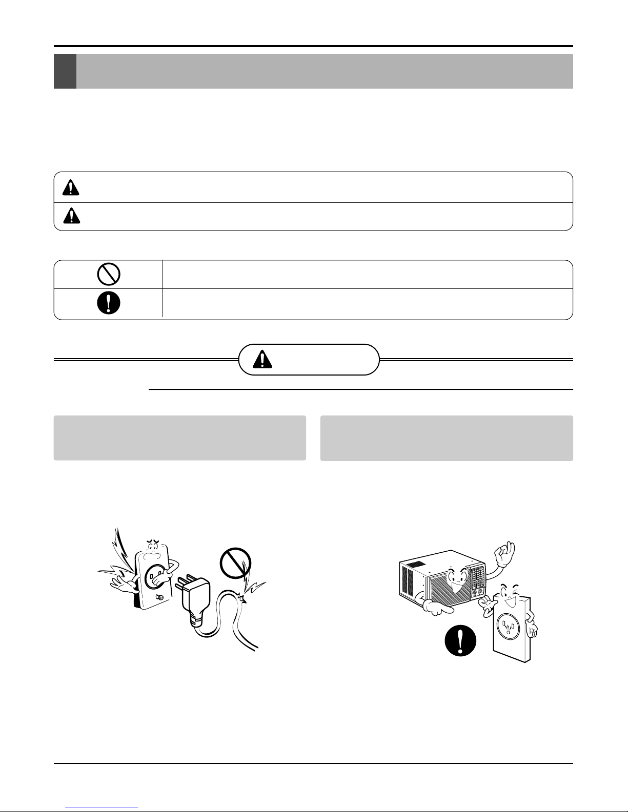
WARNING
■ Installation
Do not use damaged power cord plugs, or a
loose socket.
• There is risk of fire or electric shock.
Always use the power plug and socket with
the ground terminal.
• There is risk of electric shock.
Be sure not to do.
Be sure to follow the instruction.
4 Room Air Conditioner
Safety Precautions
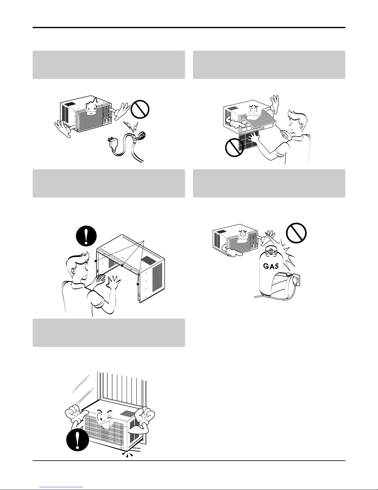
Do not modify or extend the power cord.
•Thereisriskorfireorelectricshock.
Do not install, remove, or re-install the unit by
yourself.
• There is risk of fire, electric shock, explosion, or injury.
Be cautious when unpacking and installing
the product.
• Sharp edges could cause injury. Be especially careful
of the case edges and the fins on the condenser and
evaporator.
Do not store or use flammable gas or combustibles near the air conditioner.
• There is risk of fire or failure of product.
Be sure the installation area does not deteriorate with age.
• If the base collapses, the air conditioner could fall with
it, causing property damage, product failure, and personal injury.
Gasolin
Sharp edges
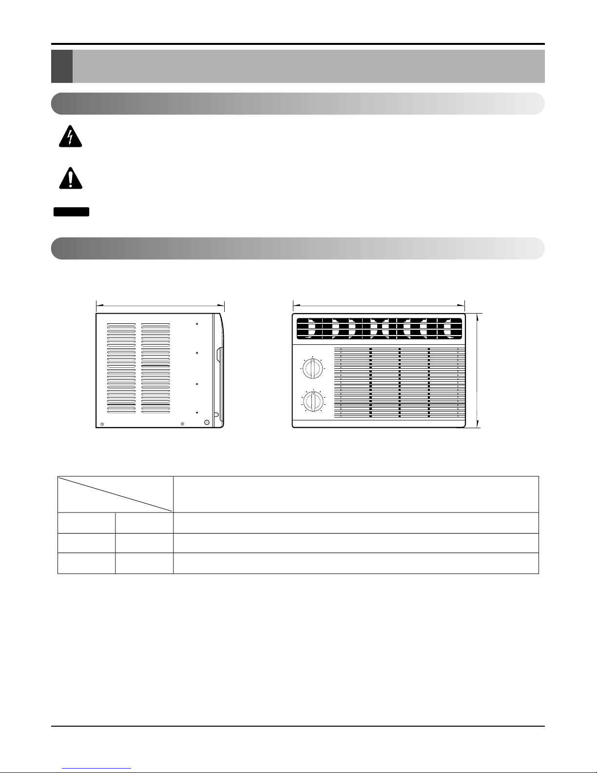
Dimensions
Dimensions
H
D
W
Operation
High
Fan
Low
Fan
High
Cool
Off
Low
Cool
Thermostat
1
2
3
4
5
6
7
8
9
W mm(inch) 472(189/16")
H mm(inch) 312(121/4")
D mm(inch) 370(14
9
/16")
Model
Dimension
All Model
Outside Dimensions
This symbol alerts you to the risk of electric shock.
This symbol alerts you to hazards that could cause harm to the
air conditioner.
This symbol indicates special notes.
NOTICE
Symbols Used in this Manual
Service Manual 5
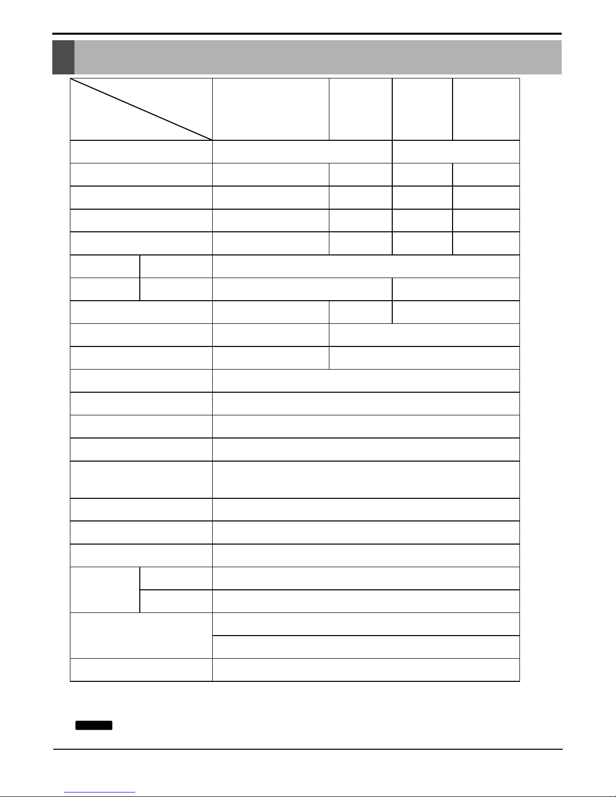
W051CA W061CA LA050MG LA060MG1
5050 Btu/h 6000 Btu/h 5500KJ/H 6000KJ/H
520 620 520 555
4.8 5.8 2.4 2.5
9.7BTU/W.h 9.7BTU/W.h 10.6KJ/H-W 10.8KJ/H-W
OPERATING
CONDITION
220 270
Ø5 2R 10C SLIT-FIN
Ø7 1R 14C, LOUVERED-FI
N
* DB:Dry Bulb
**WB:Wet Bulb
1. SPECIFICATIONS
(3 WIRE WITH GROUDING)
ATTACHMENT PLUG (CORD-CONNECTED TYPE)
DRAIN PIPE OR SPLASHED BY FAN SLINGER
TOP DOWN CHASSIS
2WAY (RIGHT & LEFT)
OVERLOAD PROTECTOR(Internal)
INTERNAL THERMAL PROTECTOR
COMPRESSOR
FAN MOTOR
CONSTRUCTION
AIR DIRECTION CONTROL
DRAIN SYSTEM
PROTECTOR
POWER CORD
OPERATION CONTROL
ROOM TEMP. CONTROL
FAN MOTOR
FAN, OUTDOOR
FAN SPEEDS, FAN/COOLING
FAN, INDOOR
CONDENSER
EVAPORATOR
REFRIGERANT (R-22) CHARGE
INDOOR (°C)
OUTDOOR (°C)
E.E.R (BTU/W.h)
RUNNING CURRENT (A)
INPUT (W)
COOLING CAPACITY
POWER SUPPLY
. MODELS
. .
ITEMS
1ø, 115V~, 60Hz 1ø, 230V~, 60Hz
27(DB)* 19(WB)**
TURBO FAN
Ø7 2R 10C SLIT-FIN
Ø5 2R 14C, LOUVERED-FIN
35(DB)* 24(WB)** 35(DB)* 27(WB)**
PROPELLER TYPE FAN WITH SLINGER-RING
4 POLES
2/2
250
ROTARY SWITCH
THERMOSTAT
SPECIFICATIONS ARE SUBJECT TO MINOR CHANGE WITHOUT NOTICE FOR FURTHER
IMPROVEMENT.
NOTICE
6 Room Air Conditioner
Product Specifications
Product Specifications
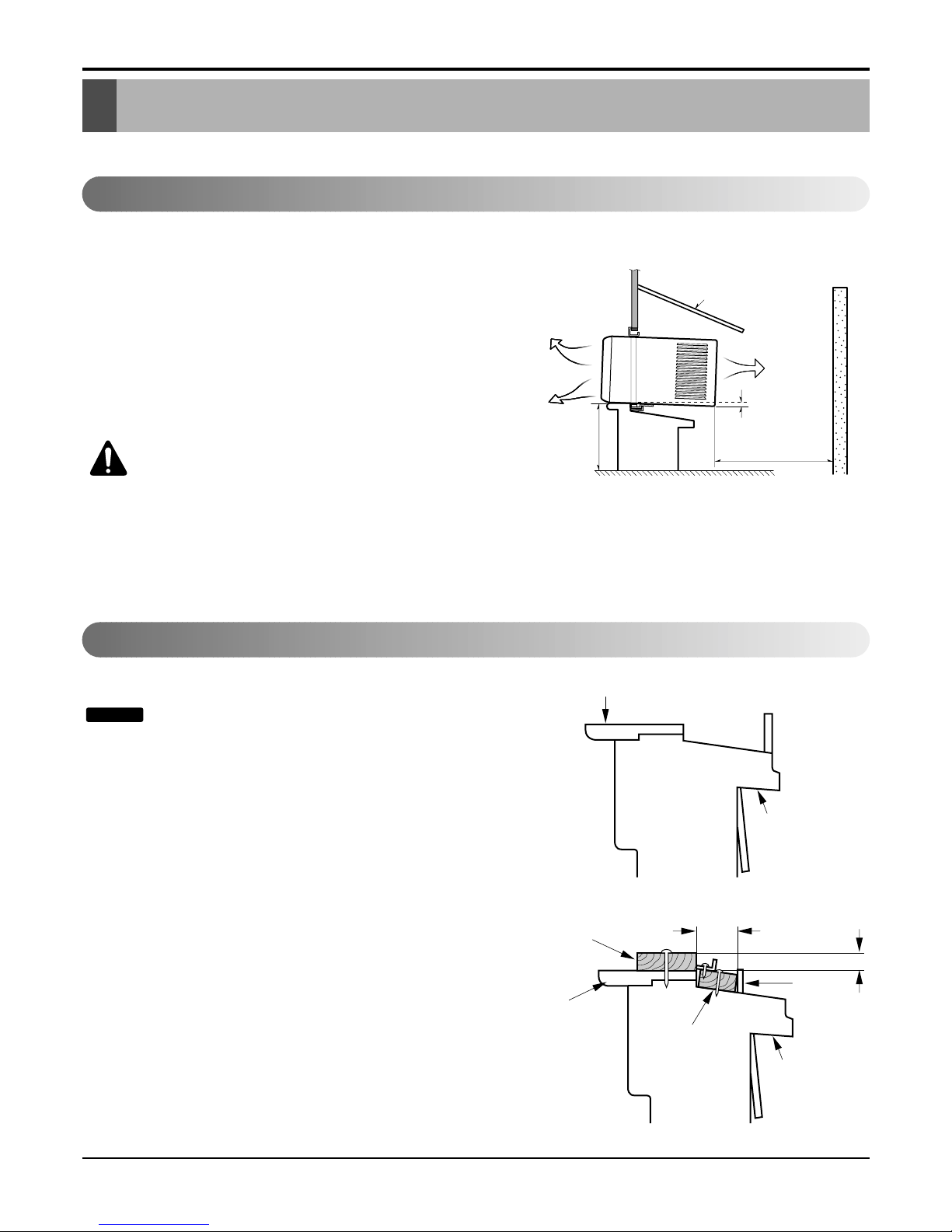
Window Requirements
All supporting parts should be secured to firm
wood, masonry, or metal.
1. This unit is designed for installation in standard double
hung windows with actual opening widths of 22" to 36".
The upper and lower sash must open sufficiently to allow
a clear vertical opening of 13" from the bottom of the
sash to the window stool.
2. If storm window presents interference, fasten a 2" wide
wood strip to the inner window sill across the full width of
the sill. The wood strip should be thick enough to raise
the height of the window sill so that the unit can be
installed without interference by the storm window frame.
See Figure. 3. Top of wood strip should be approximately
3/4" higher than the storm window frame (STORM WINDOW FRAME) or wood strip (OUTDOORS) to help condensation to drain properly to the outside.
3. Install a second wood strip (approximately 6" long by
11/2" wide and same thickness as first strip) in the center
of the outer sill flush against the back off the inner sill.
This will raise the L bracket as shown Figure. 3.
4. If the distance between STORM WINDOW FRAME and
WOOD STRIP MOUNTED ON TOP OF INNER SILL is
more than 1", two of wood strip are not necessary.
NOTICE
Installation
Installation
Select the Best Location
How to Install
This air conditioner is designed with a button-down chassis so it can be easily installed in a window.
1. To prevent vibration and noise, make sure the unit is
installed securely and firmly.
2. Install the unit where the sun does not shine directly on
the unit.
3. The outside of the cabinet must extend outward for at
least 10" and there should be no obstacles, such as a
fence or wall, within 20" from the back of the cabinet
because it will prevent heat radiation of the condenser.
Restriction of outside air will greatly reduce the cooling
efficiency of the air conditioner.
CAUTION: All side louvers of the cabinet
must remain exposed on the outdside of
the structure.
4. Install the unit slanted slightly so the back is slightly
lower than the front (about 1/4"). This will force condensed water to the outside.
5. Install the unit with the bottom about 30"~60" above the
floor level.
ABOUT / "
Over 20"
HEAT
RADIATION
FENCE
AWNING
OUTSIDE
INSIDE
OOLED AIR
30"-60"
1
4
OUTDOORSINDOORS
INNER SILL
OUTER
SILL
INNER
SILL
WOOD STRIP MOUNTED
ON TOP OF INNER SILL
WOOD STRIP
FOR
L
BRACKET
3
/4"
CLEARANCE
1" MAX.
STORM
WINDOW
FRAME
OUTDOORSINDOORS
OUTER
SILL
Figure 1
Figure 2
Figure 3
Service Manual 7
Operation
Feature
Insulation Resistance Test
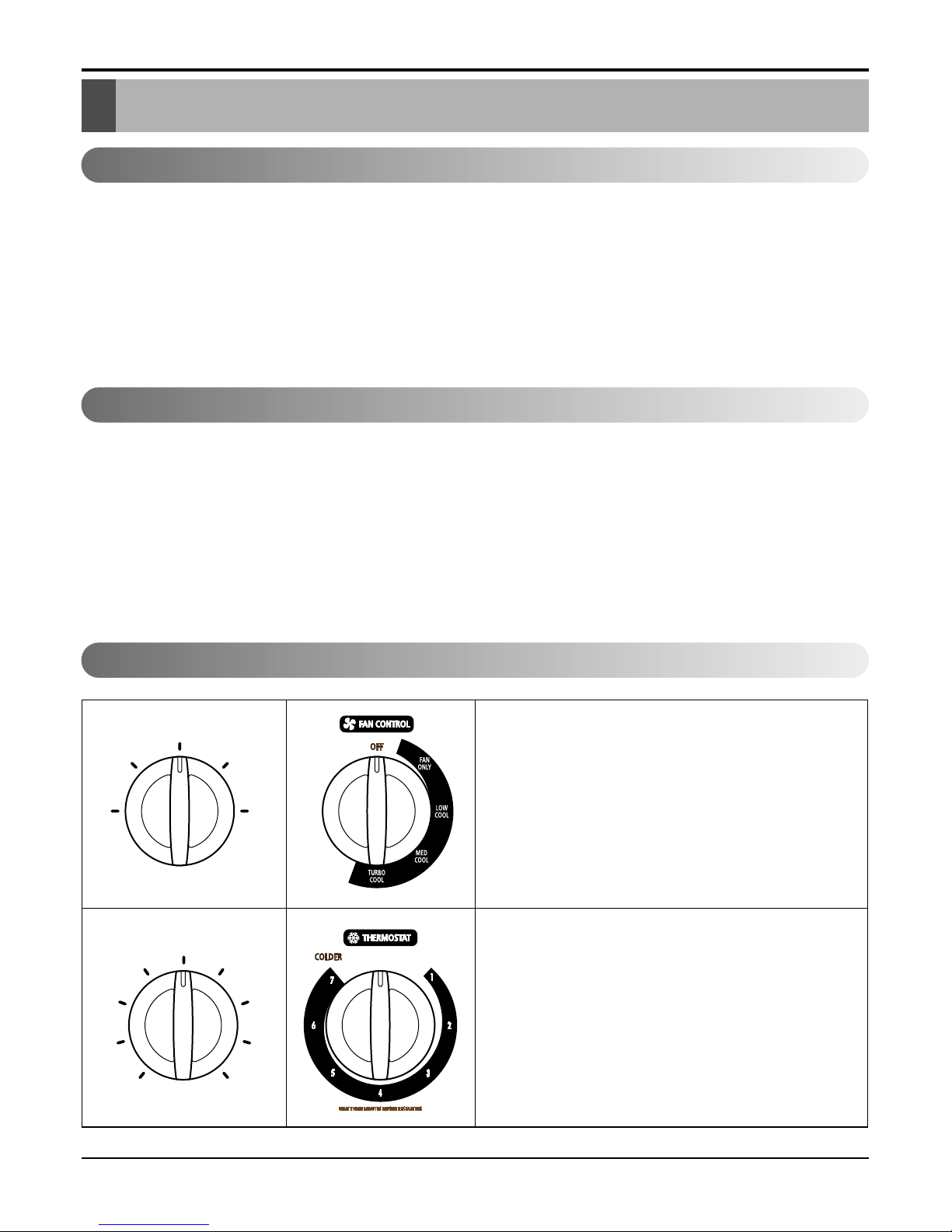
About the jControls or the Air Conditioner
• DESIGNED FOR COOLING ONLY
• POWERFUL AND INCREDIBLE COOLING
• TOP-DOWN CHASSIS FOR THE SIMPLE INSTALLATION AND SERVICE
• BUILT-IN ADJUSTABLE THERMOSTAT
• WASHABLE ONE-TOUCH FILTER
• COMPACT SIZE
INSULATION RESISTANCE TEST
1. Unplug the power cord and connect a jumper between 2 pins (black and white).
2. The grounding conductor (green or green and yellow) is to be open.
3. Measure the resistance value with an ohm meter between the jumpered lead and each exposed metallic part
on the equipment at all positions [except Off] of the ROTARY SWITCH.
4. The value should be over 1 MΩ.
Operation
Operation
High
Fan
Low
Fan
High
Cool
Off
Low
Cool
Thermostat
1
2
3
4
5
6
7
8
9
Off - Turns air conditioner off.
High Fan - High speed fan operation without cooling.
Low Fan -Low speed fan operation without cooling.
High Cool - Cooling with high speed fan operation.
Low Cool - Cooling with low speed fan operation.
FAN ONLY- Fan operation without cooling.
TURBO COOL - Cooling with high speed fan operation.
This automatically controls the temperature of the
indoor air.
Turn the knob so that arrow points to the larger marks
for greater cooling.
Point the arrow to the smaller marks for more moderate cooling.
(i.e. the higher number, the greater cooling)
8 Room Air Conditioner
 Loading...