

LG L9322 Series, L9322-BN, L9322-BP Owner's Manual

Please read this manual carefully before operating your set and retain it for future reference.
1112 (V1.0)
MODELS
L9322 Series
OWNER’S MANUAL
Dome Camera
1
Safety Information
Safety Information
2
1 Safety Information
CAUTION
RISK OF ELECTRIC SHOCK
DO NOT OPEN
CAUTION: TO REDUCE THE RISK OF ELECTRIC SHOCK
DO NOT REMOVE COVER (OR BACK)
NO USER-SERVICEABLE PARTS INSIDE
REFER SERVICING TO QUALIFIED SERVICE PERSONNEL.
This lightning flash with arrowhead symbol within an equilateral triangle is intended
to alert the user to the presence of uninsulated dangerous voltage within the
product’s enclosure that may be of sufficient magnitude to constitute a risk of electric
shock to persons.
The exclamation point within an equilateral triangle is intended to alert the user to
the presence of important operating and maintenance (servicing) instructions in the
literature accompanying the product.
FCC WARNING: This equipment may generate or use radio frequency energy. Changes or modifications to this
equipment may cause harmful interference unless the modifications are expressly approved in the instruction
manual. The user could lose the authority to operate this equipment if an unauthorized change or modification
is made.

1
Safety Information
Safety Information
3
REGULATORY INFORMATION: FCC Part 15
This equipment has been tested and found to comply with the limits for a Class A digital device, pursuant
to Part 15 of the FCC Rules. These limits are designed to provide reasonable protection against harmful
interference when the equipment is operated in a commercial environment.
This equipment generates, uses, and can radiate radio frequency energy and, if not installed and used in
accordance with the instruction manual, may cause harmful interference to radio communications.
Operation of this equipment in a residential area is likely to cause harmful interference in which case the user
will be required to correct the interference at his own expense.
• A suitable conduit entries, knock-outs or glands shall be provided in the cable entries of this product in
the end user.
• Caution: Danger of explosion if battery is incorrectly replaced. Replaced only with the same or equivalent
type recommended by the manufacturer. Dispose of used batteries according to the manufacturer’s
instructions.
• Holes in metal, through which insulated wires pass, shall have smooth well rounded surfaces or shall be
provided with brushings.
This Class A digital apparatus complies with Canadian ICES-003.
Cet appareil numérique de la classe A est conforme à la norme NMB-003 du Canada.
Warning: Do not install this equipment in a confined space such as a bookcase or similar unit.
Warning: Wiring methods shall be in accordance with the National Electric Code, ANSI/NFPA 70.
Warning: This is a class A product. In a domestic environment this product may cause radio interference in
which case the user may be required to take adequate measures.
Warning: To reduce a risk of fire or electric shock, do not expose this product to rain or moisture.
Caution: This installation should be made by a qualified service person and should conform to all local codes.
Caution: To avoid electrical shock, do not open the cabinet. Refer servicing to qualified personnel only.
Caution: The apparatus shall not be exposed to water (dripping or splashing) and no objects filled with liquids,
such as vases, shall be placed on the apparatus.
To disconnect power from mains, pull out the mains cord plug. When installing the product, ensure that the
plug is easily accessible.
1
Safety Information
Safety Information
4
LG Electronics hereby declares that this/these product(s) is/are in compliance with the
essential requirements and other relevant provisions of Directive 2004/108/EC, 2006/95/EC
and 2009/125/EC.
European Standards Centre:
Veluwezoom 15, 1327 AE Almere, The Netherlands (Tel : +31-(0)36-547-8888)
• Please note that this is NOT a Customer Service contact point. For Customer Service
Information, see Warranty Card or contact the dealer that you purchased this product.
Disposal of your old appliance
1. When this crossed-out wheeled bin symbol is attached to a product it means the product
is covered by the European Directive 2002/96/EC.
2. All electrical and electronic products should be disposed of separately from the municipal
waste stream via designated collection facilities appointed by the government or the local
authorities.
3. The correct disposal of your old appliance will help prevent potential negative consequences for the environment and human health.
4. For more detailed information about disposal of your old appliance, please contact your
city office, waste disposal service or the shop where you purchased the product.
EEE Compliance with Directive. (for Turkey only)
1
Safety Information
Safety Information
5
IMPORTANT SAFETY INSTRUCTIONS
1. Read these instructions.
2. Keep these instructions.
3. Heed all warnings.
4. Follow all instructions.
5. Do not use this apparatus near water.
6. Clean only with dry cloth.
7. Do not block any ventilation openings. Install in accordance with the manufacturer’s instructions.
8. Do not install near any heat sources such as radiators, heat registers, stoves, or other apparatus (including
amplifiers) that produce heat.
9. Do not defeat the safety purpose of the polarized or grounding-type plug. A polarized plug has two
blades with one wider than the other. A grounding type plug has two blades and a third grounding
prong. The wide blade or the third prong are provided for your safety. If the provided plug does not fit
into your outlet, consult an electrician for replacement of the obsolete outlet.
10. Protect the power cord from being walked on or pinched particularly at plugs, convenience receptacles,
and the point where they exit from the apparatus.
11. Only use attachments/accessories specified by the manufacturer.
12. Use only with the cart, stand, tripod, bracket, or table specified by the manufacturer, or sold with the
apparatus. When a cart is used, use caution when moving the cart/apparatus combination to avoid injury
from tip-over.
13. Unplug this apparatus during lightning storms or when unused for long periods of time.
14. Refer all servicing to qualified service personnel. Servicing is required when the apparatus has been damaged in any way, such as power-supply cord or plug is damaged, liquid has been spilled or objects have
fallen into the apparatus, the apparatus has been exposed to rain or moisture, does not operate normally,
or has been dropped.

1
Safety Information
Safety Information
6
Safety Precautions
• Do not attempt to disassemble the camera
To prevent electric shock, do not remove screws or covers. There are no user serviceable parts inside. Ask
a qualified service personnel for servicing.
• Avoid the camera with direct sunlight
Do not aim the camera at bright objects. Whether the camera is in use or not, never face it with direct
sunlight or other extremely bright objects. Otherwise blooming or smear may be caused.
• Handle the camera with care
Do not abuse the camera. Avoid striking, shaking, etc. The camera could be damaged by improper
handling or storage.
• Do not use strong solvents or detergents
Use a dry cloth to the camera when it is dirty. If it is hard to remove the dirt on the camera, use a mild
detergent and wipe it gently.
• Do not install this camera upside down
This camera is designed for mounting on the ceiling or wall. If you install this camera upside down, for
example, mounted on the floor, it may cause malfunction.
• Do not use the camera in such places as shown below.
The lens may become cloudy due to condensation if the camera is used under the following conditions.
> Rapid temperature fluctuation by switching an air conditioner on and off.
> Rapid temperature fluctuation due to frequent door opening and closing.
> Use in an environment where eyeglasses become foggy.
> Use in a room filled with cigarette smoke or dust.
If the lens becomes cloudy due to condensation, remove the dome cover and wipe all moist surfaces with
a soft cloth.
• Before operating, please check proper temperature, humidity and power source ratings.
Use the camera under conditions where temperature is from -10 °C to 50 °C and humidity is below 80 %.
The input power source is DC 12 V or AC 24 V.
• This camera must always be operated by AC 24 V or DC 12 V Certified/Listed, class 2 power supply
only.
• Consumables
Parts having contacts such as the lens-drive motors, cooling fan built inside the camera are subject to
wear with time. About replacement and maintenance of such parts, please ask the nearest service center.

1
Safety Information
Safety Information
7
Camera Installation Location
Discuss the installation location for the camera with your retailer, and select a place that is strong enough for
the installation.
• Install the camera on a ceiling (concrete, etc.) at a location that is sufficiently strong to support it.
• Install the camera body on the foundation section of the building or sections having sufficient bearing
strength.
Never install or use the camera in the following locations
• Do not install it in areas exposed to direct sunlight or rain.
• Do not install the camera near the air outlet of an air conditioner.
• Near a swimming pool or other areas where chemicals are used.
• Food preparation areas and other locations where there are large amounts of steam vapor and oil, in
flammable atmospheres, other special environments.
• Areas where radiation, X-rays, strong electric waves, or magnetism is generated.
• At sea, in coastal areas, or in areas where corrosive gas is being generated.
• Areas outside of the allowable ambient operating temperature range.
About Static Electricity Removal
Before installing the camera, touch a metal case or other metallic parts with your hand to remove static
electricity from your body.
• Do not install in areas subjected to high amounts of humidity or dust.
• Doing so may cause internal components to damage more easily or malfunction.
• Do not wire cables near power lines.
Tightening the Screws
Screws should be tightened sufficiently in accordance with the materials and structure of the installation
location. After tightening the screws, visually inspect them to make sure there is no unevenness and that each
screw is tight.

Table of Contents
8
Table of Contents
1 Safety Information
5 IMPORTANT SAFETY
INSTRUCTIONS
6 Safety Precautions
7 Camera Installation Location
7 Never install or use the camera in the
following locations
7 About Static Electricity Removal
7 Tightening the Screws
2 Preparation
10 Features
12 Package Component
13 Main Part Description
3 Installation
14 Precautions
14 Connection Overview
15 Port Description
16 DIP Switch Setup
16 Camera ID Setup
17 Communication Protocol Setup
18 Baud Rate Setup
19 Terminal Resistor Setup
20 Configuration for the
Manufacturer Only
20 Mounting the camera
20 Surface mount
24 In-ceiling mount
4 Operation
26 Menu navigation
27 Setup Menu Overview
32 Menu settings
32 Camera menu settings
32 Focus setting
32 Exposure settings
35 White Balance Setting
36 DAY/NIGHT Setting
37 3D-DNR Setting

2
1
3
4
5
Table of Contents
9
38 Color Setting
39 Sharpness Setting
39 D-Effect Setting
40 Stabilizer Setting
40 Pan/Tilt Setting
40 Preset Setting
43 Group Tour Setting
44 Pattern Setting
45 Auto Pan Setting
46 Swing Setting
48 Privacy Mask Setting
49 Special Setting
53 OSD Settings
55 LANGUAGE Setting
56 ALARM Setting
57 Alarm In Setting
57 Alarm Out Setting
58 RESET Setting
58 Information
59 Initialization
59 Factory Reset
5 Appendix
60 Specifications

2
Preparation
Preparation
10
2 Preparation
Features
• High Sensitivity Support
The camera provides the high quality picture with 4.5 mm CCD and XDI-II ISP.
• Preset Position
Preset position is the function to register camera monitoring positions (preset positions). By using
LKD1000 controller, you can register presets with position number. Maximum 128 Preset Positions are
available. By entering the position numbers, you can move cameras to the preset positions. The moving
speed and holding time are adjustable.
• Preset Tour
Preset Tour is the function to go through all the registered camera monitoring positions (preset
positions).
• Group Tour
Maximum 9 group tours are able to compose the group of preset, pattern, auto pan that the operator
can program to be linked together in a sequence.
• Pattern recording function
A routine of manual operations can be stored and reproduced repeatedly. The Pan, Tilt and Zoom
controls are available for pattern recording.
The available total time of pattern differs depending on camera’s operation. When the pattern
recording is full, the pattern recording will automatically stop.
,
Note
• Privacy Mask
Privacy zone feature enables users to veil unwanted zones. This setting is used for masking unwanted
zones, hiding them from display on the monitor screen. Up to 8 zones can be registered.
• Auto Pan
The camera has an Auto Pan function that enables to keep surveillance on every detail occurring around
the specific area, which is preset to watch in advance. The camera can pan among the maximum 8
points you will set. The moving speed and holding time are adjustable.

2
Preparation
Preparation
11
• Swing
Swing is the function that a camera scans between 2 preset positions. Swing speed between 2 preset
positions can be adjusted. There are 8 Swings.
• Auto Filp
When the camera is operated to tilt through the 90°, it can be watched the opposite side of the locations
by Auto Flip of a 180° horizontally.
• Optical Zoom
The optical zoom range is 1x to 12x.
• Digital Zoom
Digital zoom enhances the systems zoom range to 12 times beyond the optical zoom limit. Total system
zoom range is 12x (1x digital zoom) to 144x (12x digital zoom).
• Alarm In Function (3 channels)
Alarm input signals are supplied from external devices through the ALARM IN connector to activate ‘go
to preset’ function.
• Alarm Out Function (2 channels)
When alarm inputs are supplied via the alarm input connector on the camera, the camera sends output
signals via the alarm output connector on the camera.
• Motion Detection Function
When there is no Pan/Tilt/Zoom motion, a camera can detect motions in video images and work with
sensor functions
• Controls by General Controller
This camera can be controlled by RS-485. Especially the camera has an excellent cost-saving effect
because it can be controlled by the general RX point of contact signal.
• Connects with maximum 256 cameras
This camera can be utilized after being connected with maximum 256 cameras. Therefore, it is capable of
performing an excellent job in the large buildings or department stores.
• Day & Night Function
This camera can be selected Color or Black & White. You can set Color in the daytime and Black & White
at night due to the low illumination. (Filter Conversion type)
• DSS (Digital Slow Shutter) Function
It is possible to highly sensitive surveillance because of DSS(Digital Slow Shutter) function.
• WDR (Wide Dynamic Range) Function
The camera can be best condition to watch easily inside or outside in the strong back light.
• Power Supply
Both of DC 12 V and AC 24 V can be used.
2
Preparation
Preparation
12
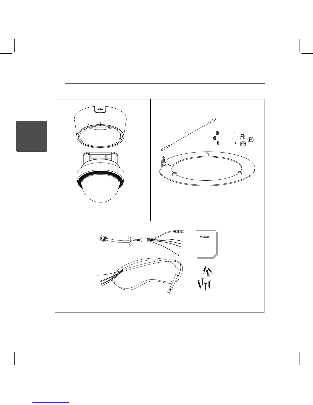
Package Component
Main Body & Surface Mount Bracket
Accessories for In-ceiling mount
[In-ceiling Plate, In-Ceiling Wire, Machine M4x50, Nut M4]
Default Accessories
[Main Cable, I/O Cable, Owner’s Manual, Screws : Tapping M4x16, Machine M3x8]
2
Preparation
Preparation
13
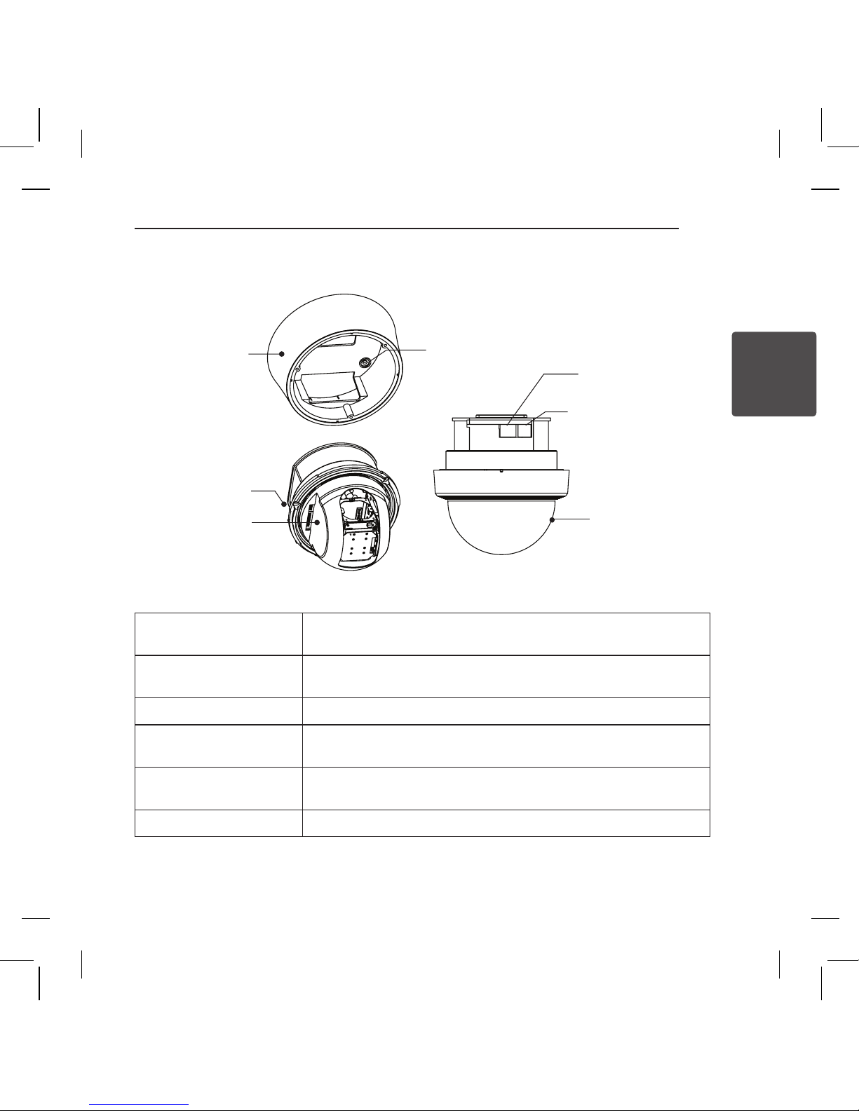
Main Part Description
Mounting Screw Hole
Main Connector
Alarm I/O Connector
Dome Cover
DIP Switch
Surface Mount
Bracket
Dome Cover
Assembly Stud
Dome Cover Do not detach the protection vinyl from the dome cover before finishing all
the installation process to protect the dome cover from scratches or dust.
Dome Cover Assembly Stud Used to line up the stud on the main body and the stud on the dome cover
when assembling the dome cover with the main body.
DIP Switch Used to set up camera IDs and protocols.
Surface Mount Bracket &
Mounting Screw Hole
Used for surface mount type, wall mount type and ceiling mount type. They
are not used for in-ceiling mount type.
Main Connector Used for the power wire, the video cable and the RS-485 communication
cable connection.
Alarm I/O Connector Used for the alarm in/out connection.
3
Installation
Installation
14
3 Installation
Precautions
• The following steps of installation and connection work should be done by qualified service personnel or
system installers and should conform to all local codes.
• Before you install and connect the camera, check and prepare the required peripheral devices and
cables.
• Before you connect the camera, turn off all devices to be connected, such as this camera and DVR.
• Do not touch the dome cover’s window.
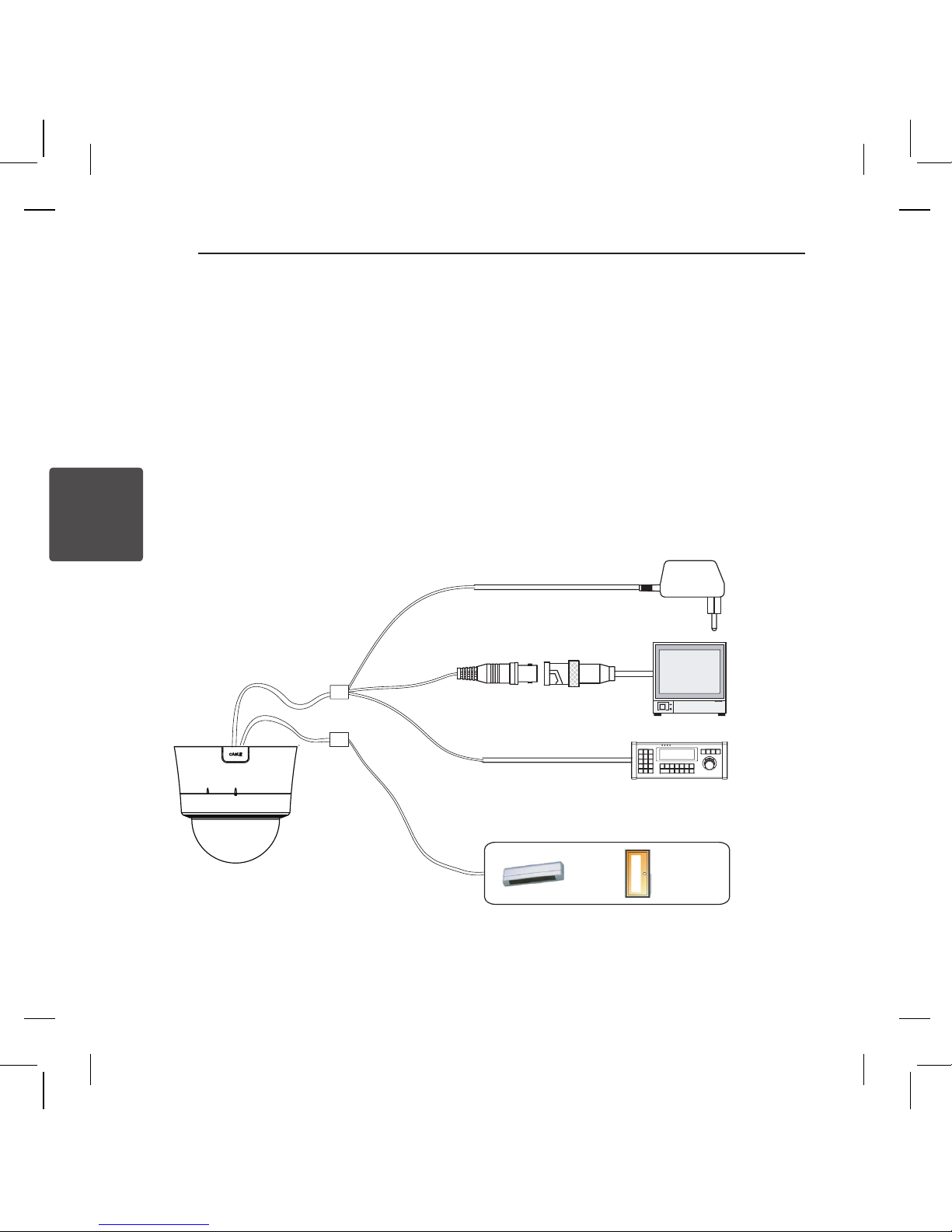
Connection Overview
Power
BNC
RS-485
Monitor
Controller / DVR
I/O Cable
Main Cable
Sensor I/O
IR
Sensor
Door
Switch
3
Installation
Installation
15
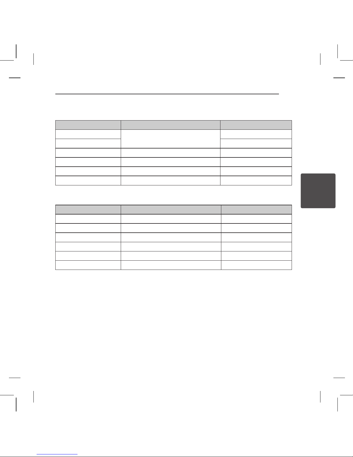
Port Description
• Main Cable
Port Pin Number Connector / Wire Color Signal
1
BNC Connector
Video +
2,4 Video -
5 Red RS-485 +
3 Yellow RS-485 -
7 Orange Power +
6,8 White Power -
• Alarm I/O Cable
Port Pin Number Wire Color Signal
1 Blue IN COM +
2 Yellow IN 1 -
3 Green IN 2 -
4 Red IN 3 -
5 Black OUT A
6 White OUT B
3
Installation
Installation
16
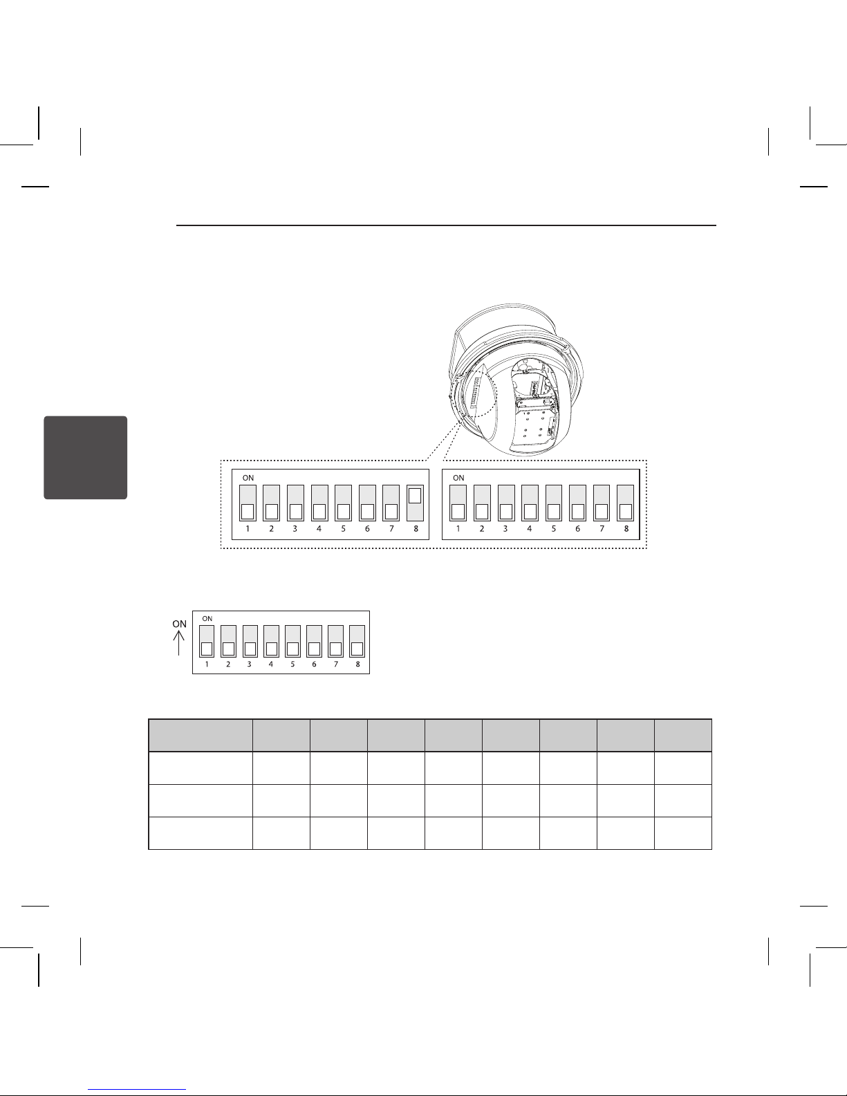
DIP Switch Setup
Before installing the camera, set up the DIP switch to configure the camera ID and the communication
protocol.
Camera ID Setup
• ID numbers of cameras are set up with binary numbers. See the examples shown below.
Pin 1 2 3 4 5 6 7 8
Binary Value 1 2 4 8 16 32 64 128
ex) ID=5 on off on off off off off off
ex) ID=10 off on off on off off off off
3
Installation
Installation
17
• The factory default of the camera ID is “0”.
• Match the camera ID with the Cam ID setting of your DVR or Controller to control the camera.
• ID 0 can not be used in Pelco-P protocol.
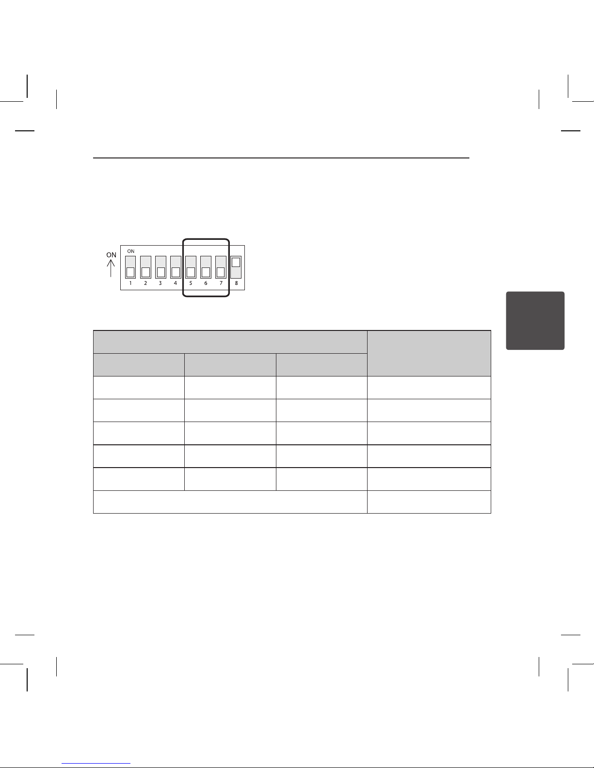
Communication Protocol Setup
• Select an appropriate Protocol with the DIP switch combination.
Switch Mode
Protocol
Pin 5 Pin 6 Pin 7
OFF OFF OFF LG Multix
ON OFF OFF PELCO-D
OFF ON OFF PELCO-P
ON ON OFF PELCO-C
ON ON ON OSD Set
Others Reserved
• Match the camera protocol with the camera protocol in the setting of your DVR or controller to control
the camera.
• Adjust the DIP switch after turning off the camera.
• The factory default protocol is “LG Multix”.
3
Installation
Installation
18
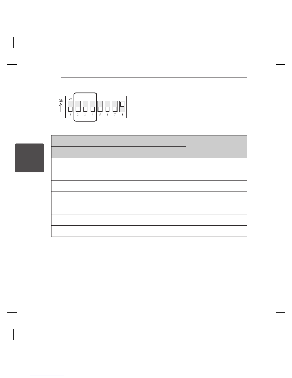
Baud Rate Setup
• Select the baud rate with the DIP switch combination.
Switch Mode
Baud Rate
Pin 2 Pin 3 Pin 4
OFF OFF OFF 9600 bps
ON OFF OFF 2400 bps
OFF ON OFF 4800 bps
ON ON OFF 19200 bps
OFF OFF ON 38400 bps
ON ON ON OSD Set
Others Reserved
• Match the baud rate with the camera’s one in the setting of your DVR or controller to control the camera.
• Adjust the DIP switch after turning off the camera
• The factory default value is 9600 bps.
3
Installation
Installation
19
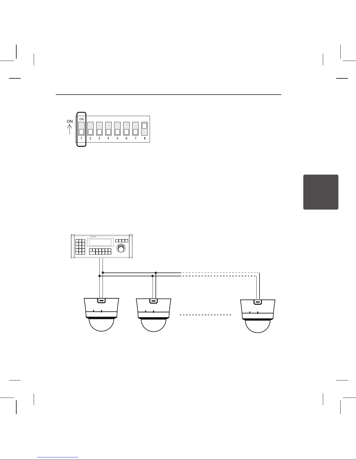
Terminal Resistor Setup
The terminal resistor is used for the following cases.
• In case that the control cable length between a camera and a controller is relatively very long (1:1
Connection)
If the communication cable length is very long, the electrical signal will bound in the terminal point. This
reflected signal causes distortion of original signal. Accordingly, the camera can be out of control. In this
case, the terminal resistor of both sides i.e. the camera and the controller must be set to ‘ON’ state.
• In case that multiple cameras are connected to a controller
Due to similar reasons with the case 1, the terminal resister of the controller and the last camera must be
set to ‘ON’ state. The last camera means the camera farthest in cable length from the controller. Do not
turn on the terminal resistor of all the cameras on the same communication cable.
#1 #2 #n
Controller
RS-485
Terminal Resistor ON
Terminal Resistor OFF Terminal Resistor OFF
Terminal Resistor ON
 Loading...