

LG L2-C362LL0, L3-C362LL0, L3-C482LL0, L2-H242GL0, L2-C242GL0 Service Manual

LG
Multi Type Air Conditioner
SERVICE MANUAL
LG
CAUTION
website http://www.lgservice.com
e-mail http://www.lgeservice.com/techsup.html
• BEFORE SERVICING THE UNIT, READ THE SAFETY
PRECAUTIONS IN THIS MANUAL.
• ONLY FOR AUTHORIZED SERVICE PERSONNEL.
MODEL: L2-C362LL0
L3-C362LL0
L3-C482LL0

2 Multi Air Conditioner
Multi Air Conditioner Service Manual
TABLE OF CONTENTS
Safety Precautions......................................................................................................................................3
Product Specifications...............................................................................................................................7
Dimensions................................................................................................................................................10
Refrigeration Cycle Diagram....................................................................................................................14
Wiring Diagram..........................................................................................................................................16
Electronic Control Device.........................................................................................................................17
Schematic Diagram...................................................................................................................................20
Functions...................................................................................................................................................24
Operation Details ......................................................................................................................................27
2-way, 3-way Valve ....................................................................................................................................34
Cycle Troubleshooting Guide ..................................................................................................................38
Electronic Parts Troubleshooting Guide ................................................................................................39
Installation.................................................................................................................................................46
Operation ..................................................................................................................................................59
Disassembly of the parts (Indoor unit) ...................................................................................................61
Exploded View and Replacement Parts List...........................................................................................63
Service Manual 3
Safety Precautions
Safety Precautions
To prevent injury to the user or other people and property damage, the following instructions must
be followed.
■ Incorrect operation due to ignoring instruction will cause harm or damage. The seriousness is
classified by the following indications.
■ Meanings of symbol used in this manual are as shown below.
WARNING
CAUTION
This symbol indicates the possibility of death or serious injury.
This symbol indicates the possibility of injury or damage.
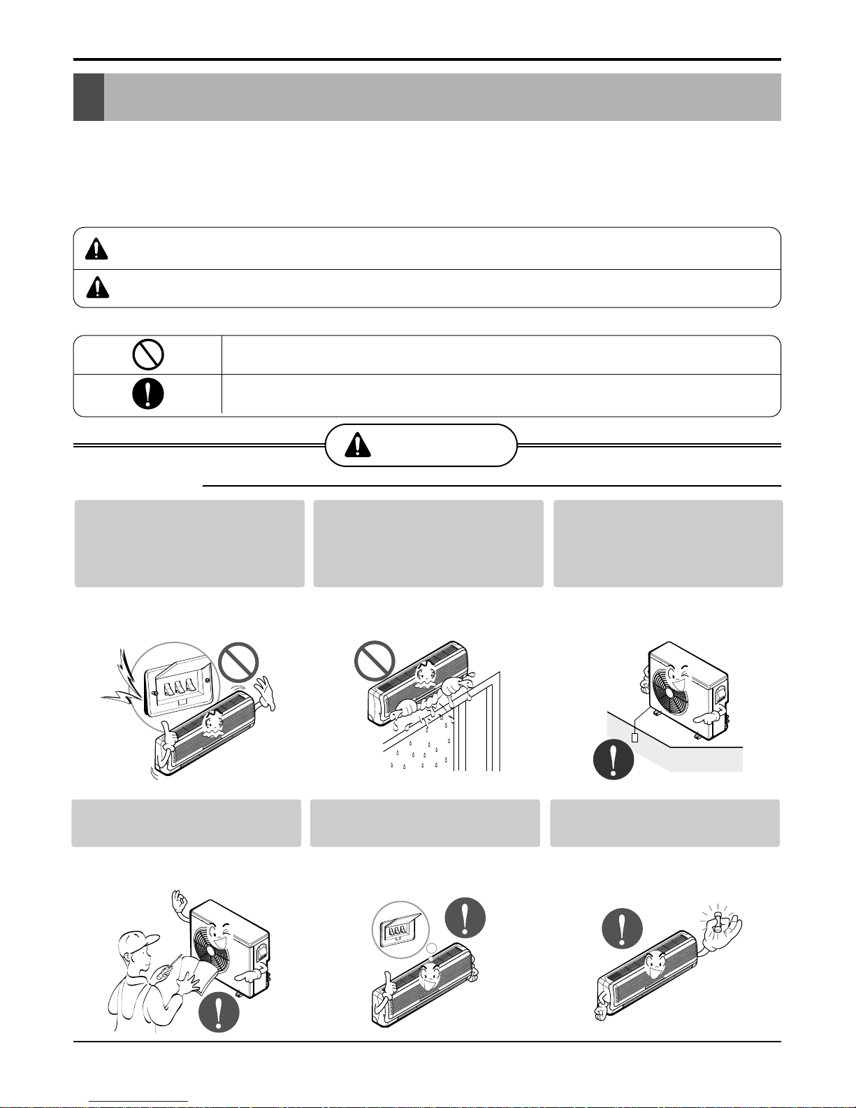
WARNING
■ Installation
Be sure not to do.
Be sure to follow the instruction.
Do not use a defective or
underrated circuit breaker.
Use this appliance on a dedicated circuit.
• There is risk of fire or electric shock.
Do not let the air conditioner
run for a long time when the
humidity is very high and a
door or a window is left open.
• Moisture may condense and wet or
damage furniture.
Always ground the product.
• There is risk of fire or electric shock.
Install the panel and the cover
of control box securely.
• There is risk of fire or electric shock.
Always install a dedicated circuit and breaker.
• Improper wiring or installation may
cause fire or electric shock
Use the correctly rated breaker or fuse.
• There is risk of fire or electric shock.
4 Multi Air Conditioner
Safety Precautions
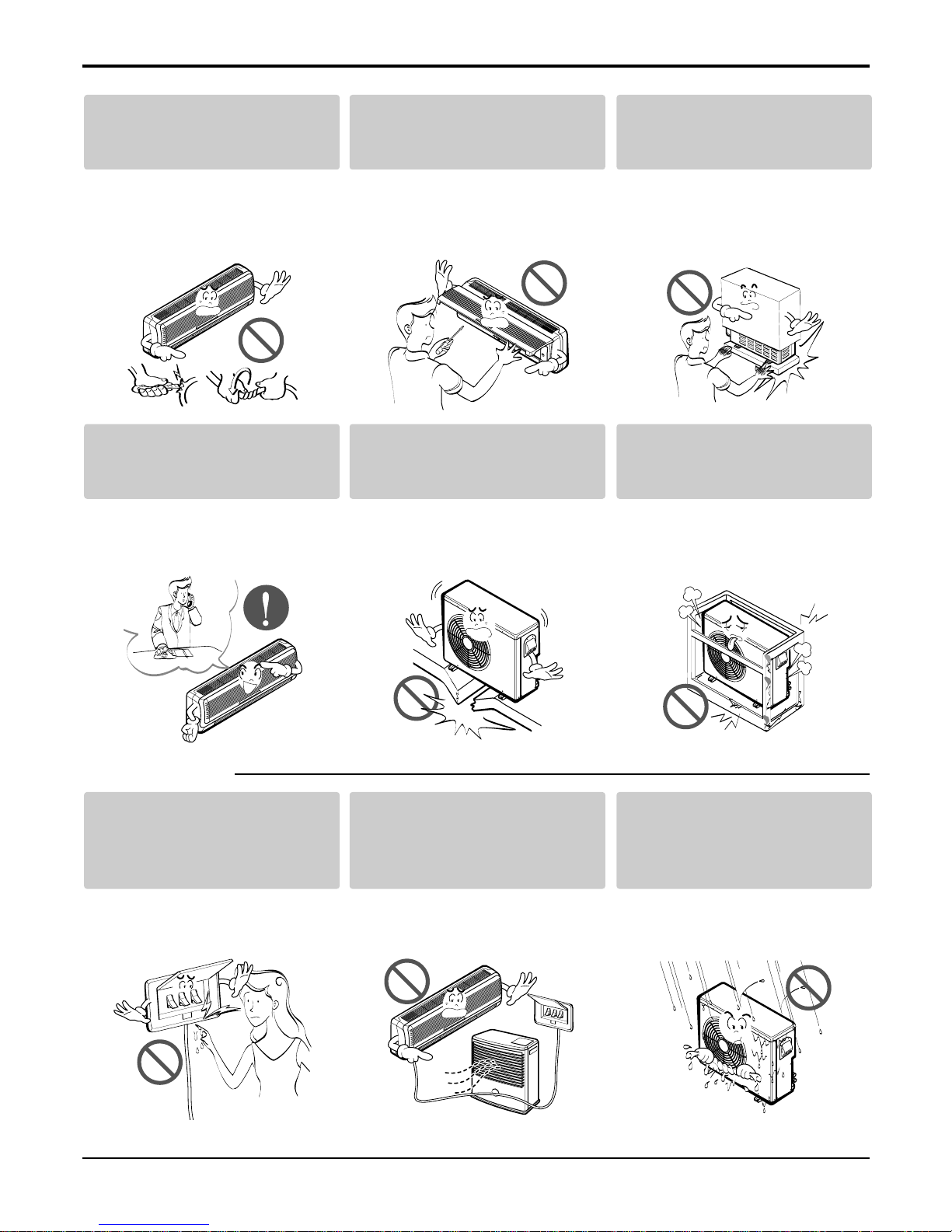
■ Operational
Do not modify or extend the
power cable.
• There is risk of fire or electric shock.
Do not install, remove, or reinstall the unit by yourself
(customer).
• There is risk of fire, electric shock,
explosion, or injury.
Be cautious when unpacking
and installing the product.
• Sharp edges could cause injury. Be
especially careful of the case edges
and the fins on the condenser and
evaporator.
For installation, always contact the dealer or an
Authorized Service Center.
• There is risk of fire, electric shock,
explosion, or injury.
Do not install the product on a
defective installation stand.
• It may cause injury, accident, or damage to the product.
Be sure the installation area
does not deteriorate with age.
• If the base collapses, the air conditioner could fall with it, causing property
damage, product failure, and personal
injury.
Do not touch(operate) the
product with wet hands.
• There is risk of fire or electrical shock.
Do not place a heater or other
appliances near the power
cable.
• There is risk of fire and electric shock.
Do not allow water to run into
electric parts.
• It may cause There is risk of fire, failure of the product, or electric shock.
Service Manual 5
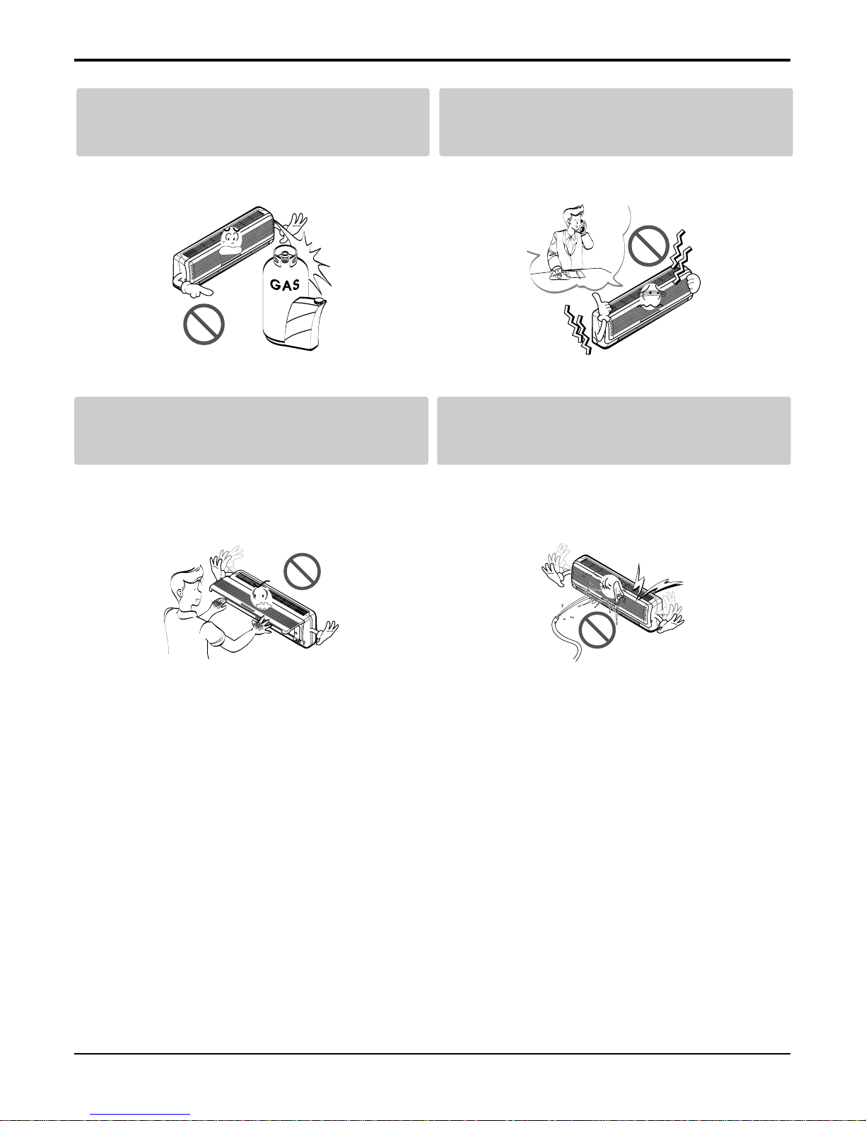
Safety Precautions
Do not open the inlet grille of the product during operation. (Do not touch the electrostatic
filter, if the unit is so equipped.)
• There is risk of physical injury, electric shock, or product failure.
Be cautious that water could not enter the
product.
• There is risk of fire, electric shock, or product damage.
Do not store or use flammable gas or combustibles near the product.
• There is risk of fire or failure of product.
If strange sounds, or smell or smoke comes
from product. Turn the breaker off or disconnect the power supply cable.
• There is risk of electric shock or fire.
Gasolin
6 Multi Air Conditioner
■ Operational
Safety Precautions
Use two or more people to lift
and transport the product.
• Avoid personal injury.
Use a soft cloth to clean. Do
not use harsh detergents, solvents, etc.
• There is risk of fire, electric shock, or
damage to the plastic parts of the product.
Do not touch the metal parts
of the product when removing
the air filter. They are very
sharp!
• There is risk of personal injury.
Do not step on or put anyting on the product.
(outdoor units)
• There is risk of personal injury and failure of product.
Do not insert hands or other objects through
the air inlet or outlet while the product is operated.
• There are sharp and moving parts that could cause personal
injury.
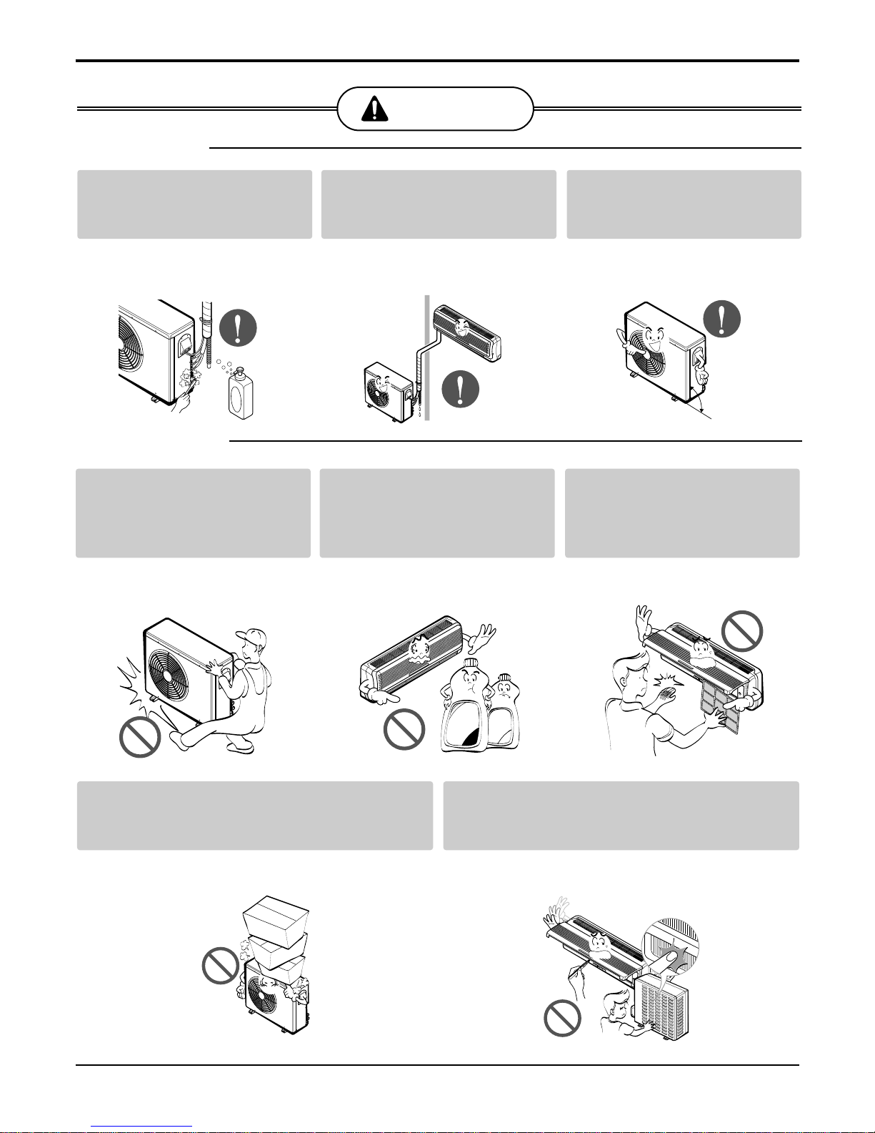
CAUTION
■ Installation
Wax
Thinner
check for gas (refrigerant)
leakage after installation or
repair of product.
• Low refrigerant levels may cause failure of product.
Install the drain hose to
ensure that water is drained
away properly.
• A bad connection may cause water
leakage.
Keep level even when
installing the product.
• To avoid vibration or water leakage.
90˚
Service Manual 7
Product Specifications
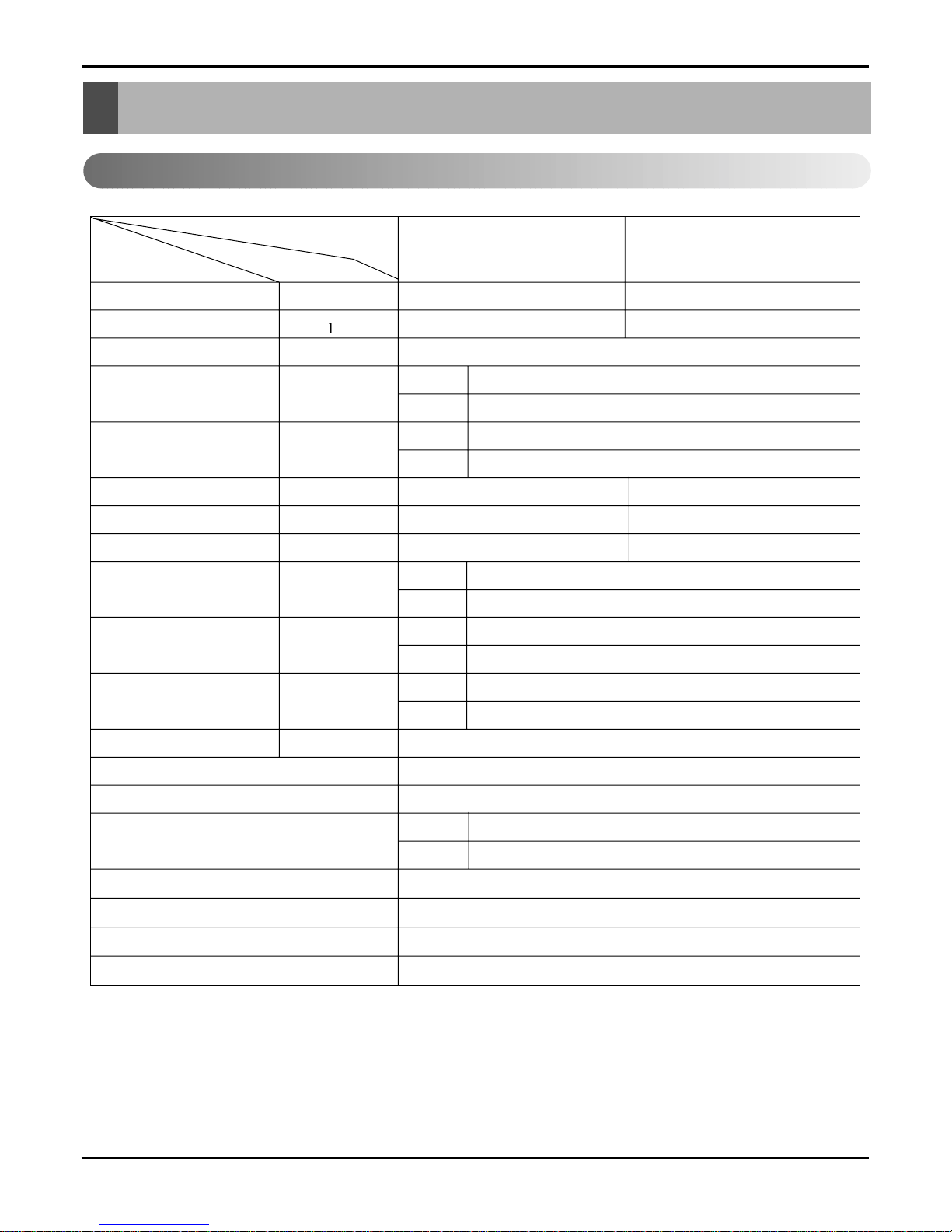
Product Specifications
1. L2-C362LL0
17,800(4,486) 35,600(8,972)
2.0 2.0 x 2
1Ø, 220, 60HZ
13.1
58
40
57
1,900 3,650
8.7 16.8
9.4 9.8
21
90
1,080 x314 x 181
870 x 800 x 320
11
71
A: 820, B: 820 (at 7.5m)
O
L.C.D Wireless
1/4"(6.35)
5/8"(15.88)
O
O
1.5mm
2
3.5mm
2
Operation
A or B unit
A + B unit
Unit
Indoor
Outdoor
Indoor
Outdoor
Indoor
Outdoor
Indoor
Outdoor
Indoor
Outdoor
Liquid
Gas
Item
Cooling Capacity Btu/h(kcal/h)
Moisture Removal /h
Power Source ø, V, Hz
Air Circulation m3/min
Noise Level(Low) dB(A)
Input W
Runnig Current A
E.E.R. Btu/h.w
Motor Output W
Dimensions(W x H x D)
mm
Net. Weight kg
Refrigerant(R-22) g
Airflow Direction Control(Up & Down)
Remocon Type
Service Valve
Drain Hose
Plasma Filter
Connecting Cable
Power Cord
8 Multi Air Conditioner
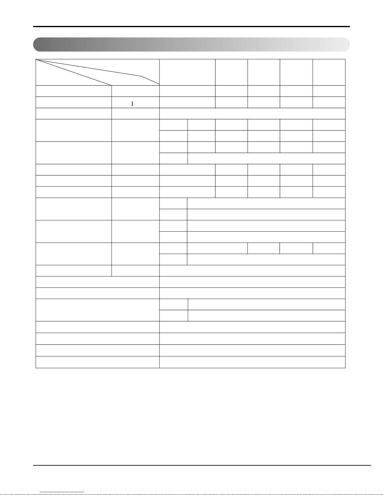
Product Specifications
2. L3-C362LL0
12,000(3,024)
13,000(3,276) 25,000(6,300) 23,800(5,998) 35,800(9,022)
1.4 1.5 2.9 2.5 3.9
1Ø, 220V, 60Hz
Indoor 9.0 9.5 9.0 + 9.5 9 + 9 9.0 x 3
Outdoor 58 - - - Indoor 37 38 - - Outdoor 57
1,300 2,100 3,200 2,400 3,600
5.7 9.3 13.6 10.1 14.8
9.2 6.2 7.8 9.9 9.9
Indoor 14.4 x 3
Outdoor 90
Indoor 888 x 287 x 170
Outdoor 870 x 800 x 320
Indoor 9 - - Outdoor 71
A: 550, B: 1,100 (at 7.5m)
O
L.C.D Wireless
Liquid 1/4"(6.35)
Gas 1/2"(12.7)
O
O
0.75mm
2
3.5mm
2
Operation
A-Unit
B or C-Unit
A+B or C B+C A+B+C
Unit
Item
Cooling Capacity Btu/h(kcal/h)
Moisture Removal /h
Power Source ø, V, Hz
Air Circulation m3/min
Noise Level(Low) dB(A)
Input W
Runnig Current A
E.E.R. Btu/h.w
Motor Output W
Dimensions(W x H x D)
mm
Net. Weight kg
Refrigerant(R-22) g
Airflow Direction Control(Up & Down)
Remocon Type
Service Valve
Drain Hose
Plasma Filter
Connecting Cable
Power Cord
Service Manual 9
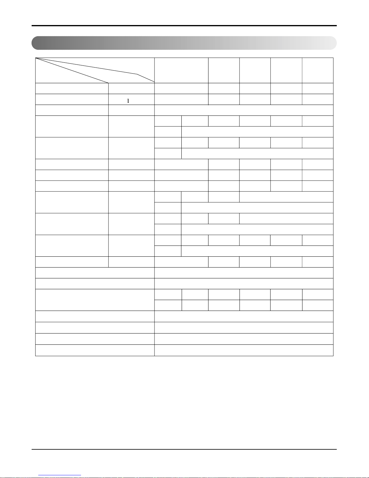
Product Specifications
3. L3-C482LL0
24,000(6,048)
16,000(4,032)
40,000(10,080)
24,000(6,048)
48,000(12,096)
2.5 2.2 4.8 3.4 6.5
1Ø, 220V, 60Hz
Indoor 14.5 9.0 14.5 + 9.0 8.2 + 8.2
14.5 + 8.2 + 8.2
Outdoor 106
Indoor 47/44/40 42/40/38 - - Outdoor 60
2,500 2,300 4,500 2,500 4,700
11.0 10.5 20.0 11.0 21.0
9.6 7.0 8.9 9.6 10.6
Indoor 22 14.4
Outdoor 80 x 2
Indoor
1,180 x 314 x 181
888 x 287 x 170
Outdoor 1,225 x 900 370
Indoor 11 9 - - Outdoor 106
1,570 1,300 - - -
O
L.C.D Wireless
Liquid
3/8"(9.52) 1/4"(6.35)
---
Gas
5/8"(15.88) 1/2"(12.7)
--O
O
0.75mm
2
5.5mm
2
Operation
A-Unit
B or C-Unit
A+B or C B+C A+B+C
Unit
Item
Cooling Capacity Btu/h(kcal/h)
Moisture Removal /h
Power Source ø, V, Hz
Air Circulation m3/min
Noise Level(Low) dB(A)
Input W
Runnig Current A
E.E.R. Btu/h.w
Motor Output W
Dimensions(W x H x D)
mm
Net. Weight kg
Refrigerant(R-22) g
Airflow Direction Control(Up & Down)
Remocon Type
Service Valve
Drain Hose
Plasma Filter
Connecting Cable
Power Cord
10 Multi Air Conditioner
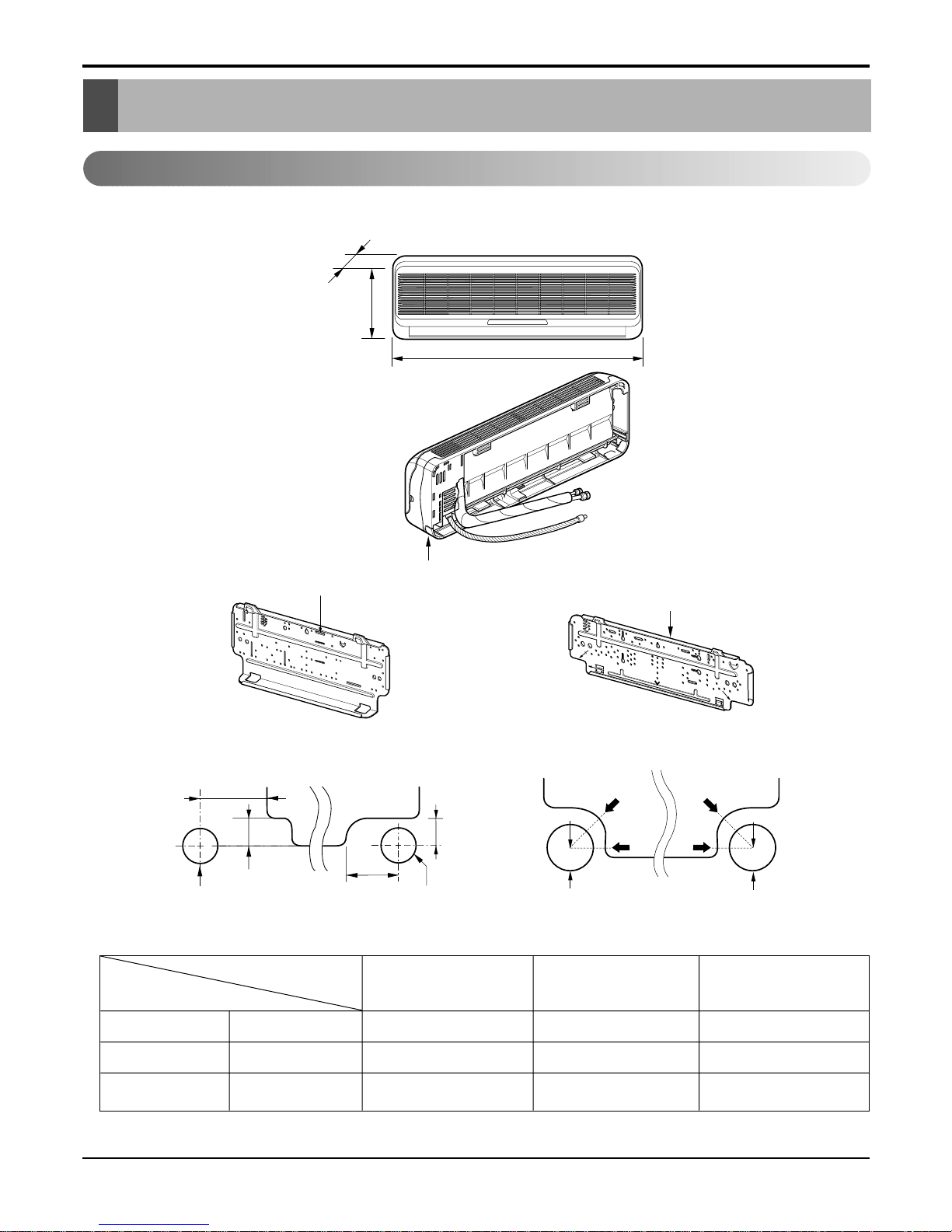
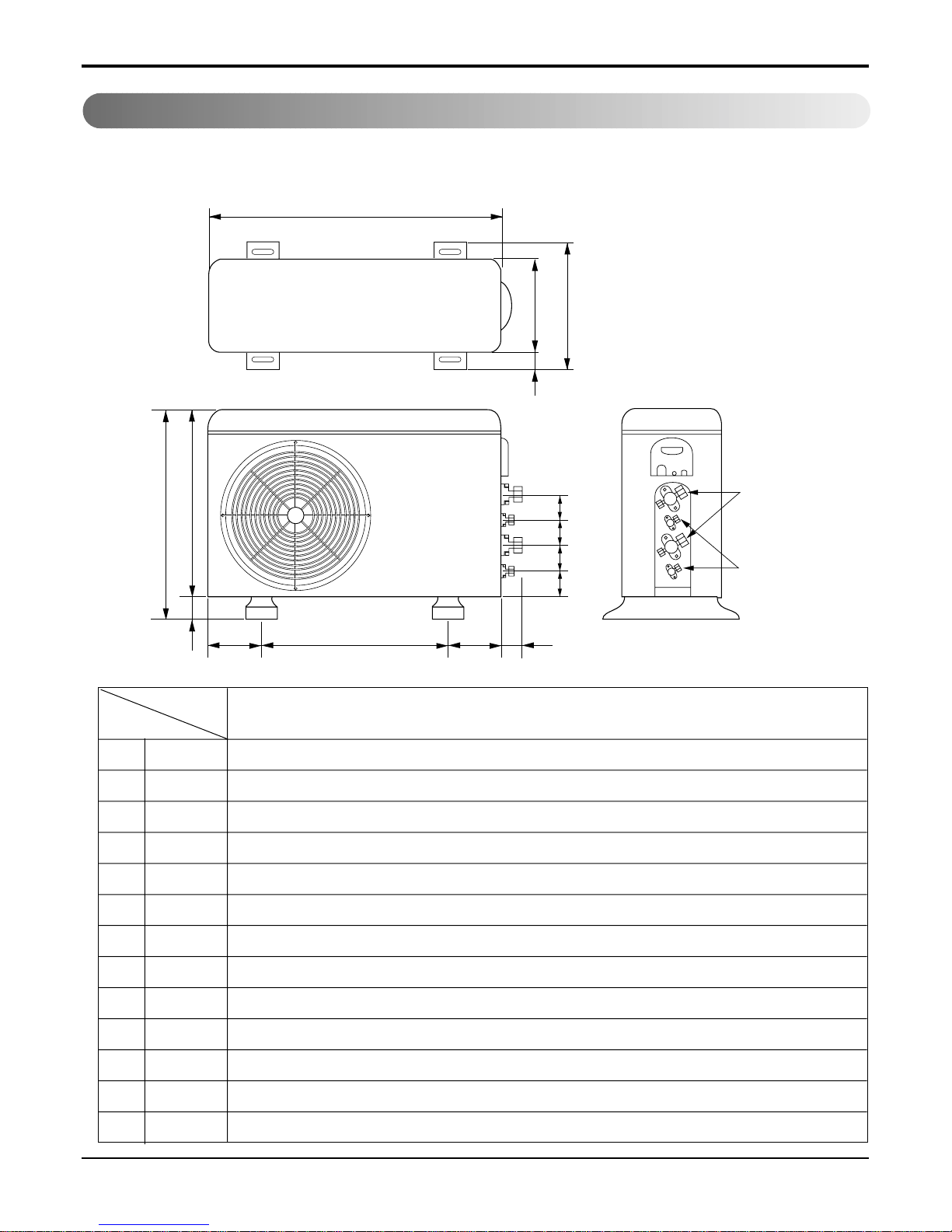
Dimensions
1. Indoor Unit
Dimensions
Installation plate
Installation plate
Right rear piping
Left rear piping
ø70mm
ø70mm
50mm
20mm
20mm
80mm
A
A
ø70mm
Center
Center
ø70mm
Left rear piping Right rear piping
A
A
D
H
W
Tubing hole cover
W mm 802 888 1,080
H mm 262 287 314
D mm 165 170 181
4.5K, 6K, 7K, 8K, 9K
Btu Series
9K, 10K, 12K Btu
Series
18K, 24K Btu
MODEL
DIM
( 4.5K, 6K, 7K, 8K, 9K )
( 4.5K, 6K, 7K, 8K, 9K )
( 9K, 10K, 12K, 18K, 24K )
( 9K, 10K, 12K, 18K, 24K )
Service Manual 11
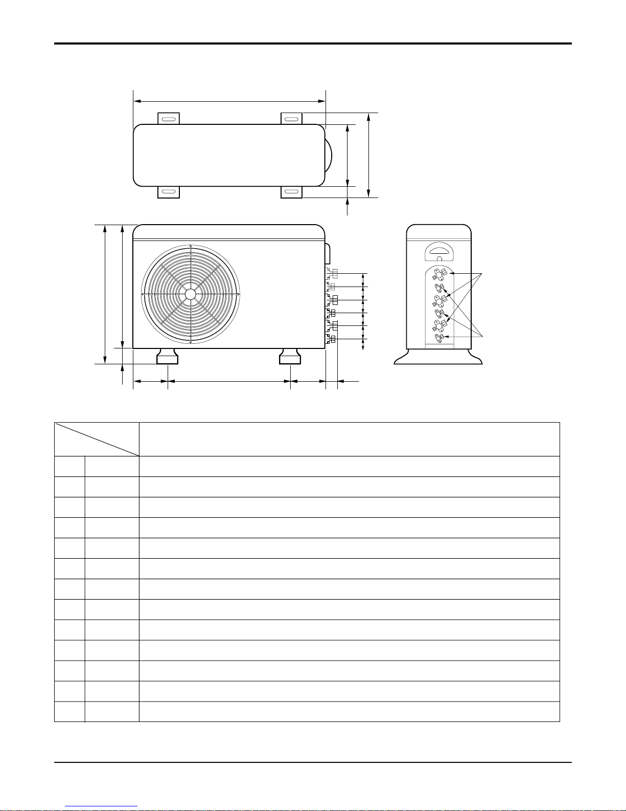
Dimensions
2. Outdoor Unit
Model: L2-C362LL0
W
D
L1
L2
L9
L4
L3
H
L10
L10
L10
L8
Gas side
3-Way valve
Liquid side
2-Way valve
L7L5L6
W mm 870
H mm 800
D mm 320
L1 mm 370
L2 mm 25
L3 mm 775
L4 mm 25
L5 mm 546
L6 mm 160
L7 mm 160
L8 mm 64
L9 mm 76.5
L10 mm 50
L2-C362LL0
MODEL
DIM
12 Multi Air Conditioner
Dimensions
L3-C362LL0
W
L5L6 L7 L8
L3
H
D
L1
L2
L4
L10L9
Gas side
3-way valve
Liquid side
2-way valve
L10L10L10L10
W mm 870
H mm 800
D mm 320
L1 mm 370
L2 mm 25
L3 mm 775
L4 mm 25
L5 mm 546
L6 mm 160
L7 mm 160
L8 mm 64
L9 mm 76.5
L10 mm 50
L3-C362LL0
MODEL
DIM
Service Manual 13
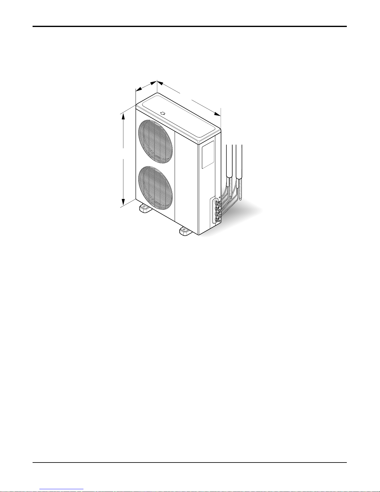
Dimensions
900
1,225
370
L3-C482LL0

14 Multi Air Conditioner
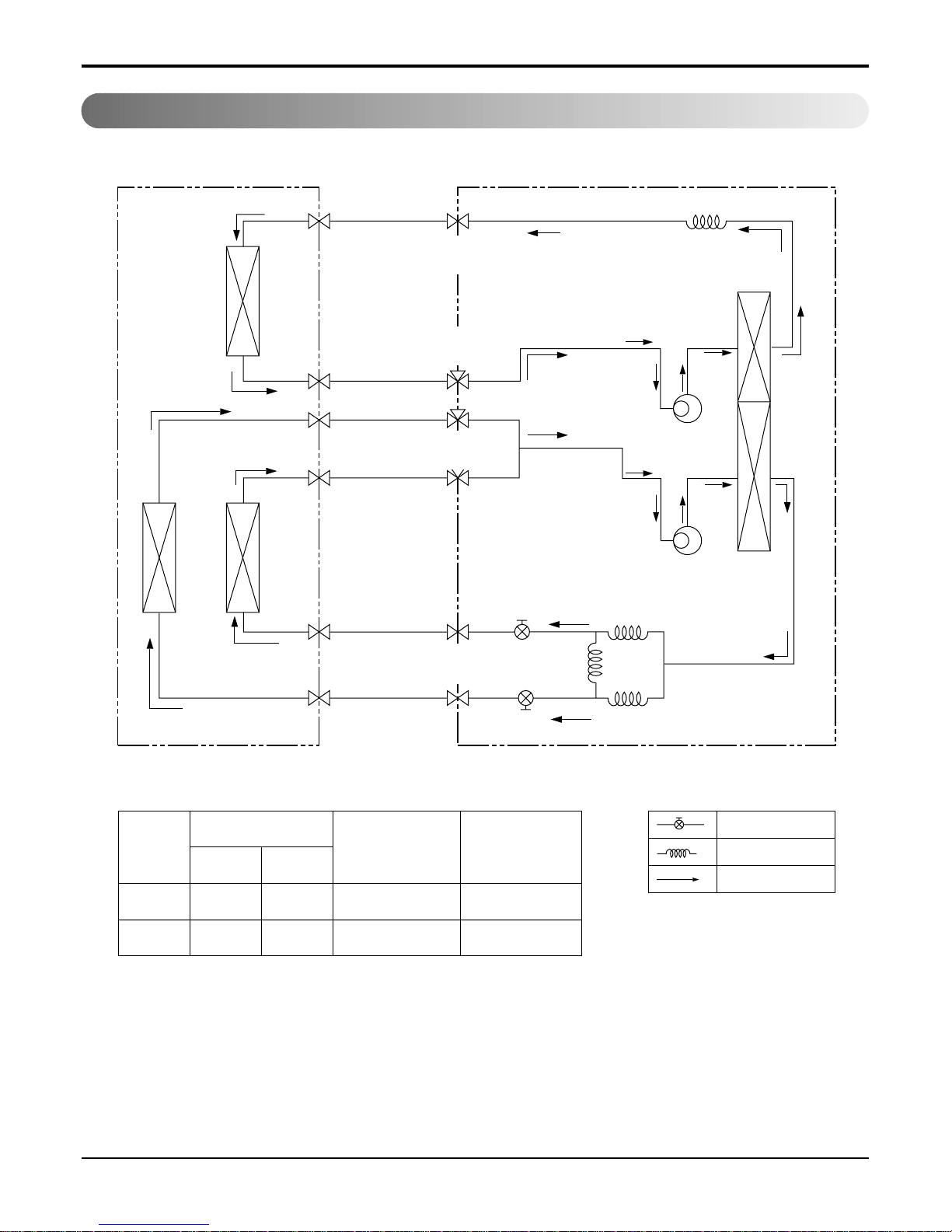
Pipe Size (Diameter : inch)
Max.
piping length
(m)
Max.
piping elevation
(m)
Gas Liquid
5/8" 1/4" 20 10
ex)
Solenoid Valve
Capillary
Cooling & Deice
A-UNIT B-UNIT
CAPILLARY TUBE
LIQUID SIDE
2-WAY VALVE
GAS SIDE
3-WAY VALVE
HEAT
EXCHANGER
(EVAPORATOR)
HEAT
EXCHANGER
(CONDENSER)
COMPRESSOR
B
COMPRESSOR
A
Pipe Size (Diameter : inch)
Max.
piping length
(m)
Max.
piping elevation
(m)
Gas Liquid
(1/2") 1/4" 10~15 5~7
ex)
Solenoid Valve
Capillary
Cooling & Deice
Heating
Indoor Unit Outdoor Unit
Heat
Exchanger
A-Unit
Heat
Exchanger
Comp-A
Comp-B
B-Unit
C-Unit
Heat
Exchanger
2- WAY
Valve
3- WAY
Valve
2- WAY
Valve
3- WAY
Valve
Refrigeration Cycle Diagram
Refrigeration Cycle Diagram
1. L2-C362LL0
2.
L3-C362LL0
Service Manual 15
Refrigeration Cycle Diagram
3. L3-C482LL0
Pipe Size
(Diameter : inch)
Indoor
B/C
Max.
piping length
(m)
Max.
piping elevation
(m)
Gas Liquid
3/8"(1/2") 1/4" 15 7
A
5/8" 3/8" 30 15
ex)
Solenoid Valve
Capillary
Cooling
Indoor Unit Outdoor Unit
Heat
Exchanger
A-Unit
Heat
Exchanger
Comp-A
Comp-B
B-Unit
C-Unit
Heat
Exchanger
2- WAY
Valve
3- WAY
Valve
2- WAY
Valve
3- WAY
Valve
16 Multi Air Conditioner
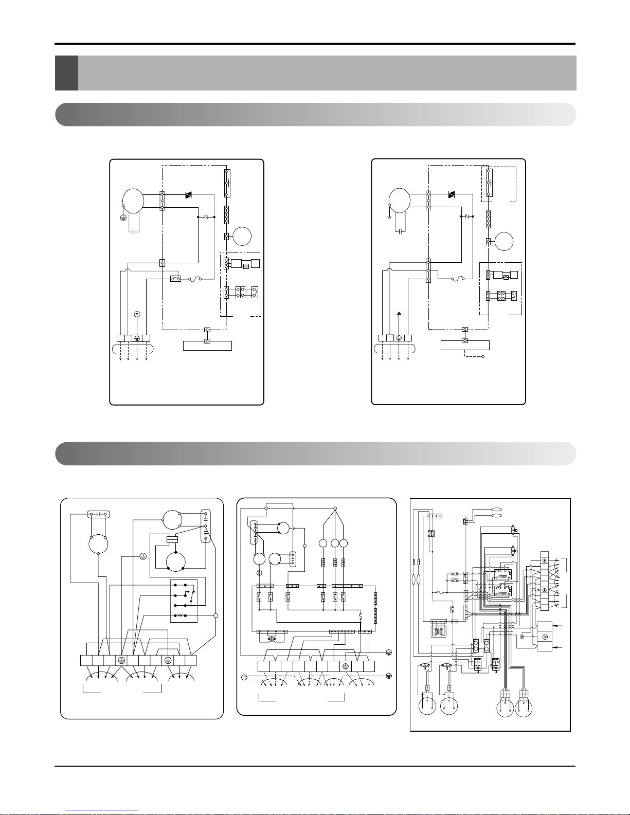
Wiring Diagram
Wiring Diagram
Indoor Unit
Outdoor Unit
3854A20080W
INDOOR WIRING DIAGRAM
CN-DISP1
CN-U/D
FUSE
AC250V/T2A
CN-TH1
TRIAC
SH-CAPA.
BR
YL
OR
BK
CN-TAB1
ZNR
CN-MOTOR
THERMISTOR
FORCED
OPERATION
AUTO
RESTART
REMOTE
CONTROL
STEP
MOTOR
MOTOR
MAIN PCB
ASM
DISPLAY PCB ASM
TO OUTDOOR UNIT
PILLAR
TERMINAL
BR
BL
YL
GN/YL
1(L) 2(N
)
3
RY-COMP.
4
3
H.V.B A/CL
RD
BK BK
BK BK
BK BK
LIMIT
S/W
OPTION
3854A20023X
INDOOR WIRING DIAGRAM
CN-DISP1
CN-U/D
FUSE
AC250V/T2A
CN-TH
SSR
SH-CAPA.
BR
YL
OR
BK
CN-POWER CN-FAN
ZNR
THERMISTOR
FORCED
OPERATION
AUTO
RESTART
REMOTE
CONTROL
STEP
MOTOR
MOTOR
MAIN PCB
ASM
DISPLAY PCB ASM
TO OUTDOOR UNIT
PILLAR
TERMINAL
BR
BL
YL
GN/YL
1(L) 2(N
)
3
OPTION
ON/OFF S/W(OPTION)
RD
BK BK
LIMIT
S/W
H.V.B A/CL
OPTION
BK BK
BK BK
RD
R
C
BR
BK
A-UNIT
TO INDOOR UNIT
OUTDOOR WIRING DIAGRAM 3854A20023Y
B-UNIT MAIN POWER
BL
OR
OR
RD
RD
BK
BK
WH
MOTOR
T/B
C
R
FCH
S
BL
WH
YL
BR
COMP
"B"
CAPACITOR
12
34
56
78
WH
WH
BK
WH
WH
WH
TERMINAL
BLOCK
POWER
RELAY
GN/YL
GN/YL
S
COMP
"A"
YL
CAPACITOR
1(L
)
1(L)1(L
)
2(N
)
2(N
)
2(N
)
33
BK
T/B1BK
CAPA.
CAPA.
OLP
RY1
RY2
RY3
RY8
RY7
RY9
CN-TH2
CN-SV
CN-TH1
FCH
1
BK
BK
BK
T/B2
WHBR
BR
BL
RD WH
GN/YL
TERMINAL
BLOCK
WH
BK
WH
BK
BK
BK
RD
BK
BK
BR
YL
YL
OR
RD
SSR
R
C
C
BK
BL RD
CN-FAN
CN-BYPASS
CN-COMP
BK
"A"
COMP
"B"
COMP
MOTOR
FUSE T3.15A
CN-POWERCN-COM
MAIN PCB ASSY
CN-TRANS
TRANS-
FORMER
A-UNIT B-UNIT
TO INDOOR UNIT
C-UNIT MAIN
POWER
OUTDOOR WIRING DIAGRAM
3854A20023Z
T/B3
BYPASS
B ROOM
C ROOM
S.V
S.V
S.V
1(L) 1(L) 1(L)
2(N) 2(N) 2(N)
33 3
OUTDOOR WIRING
DIAGRAM
MAIN PCB
ASSY
B - THERMISTOR
C - UNITB - UNIT
TO INDOOR UNIT
POWER INPUT
1Ø, 220V, 60Hz
3(N) 4(L)
1(L) 1(L)2(N) 2(N)33 3
A - UNIT
A - THERMISTOR
BK
BK
BK
BK
BK
BK
LOW
HI
BK
BK
BK
BK
YL
OR
OR
OR
BK
BK
A - MOTOR
B - MOTOR
A - COMP
RY - COMP(B)
RY - COMP(A)
FUSE 250V / 3.15A
3854A30042Z
B - COMP
YL
OR
OR OR
BK
BK
BK
BK
RD
S
CR
S
CR
S
CR
S
CR
BR YLWHBL
BK
BR
BR
BR
BR
BR
WH
WH
WH
WH
WH
TB1 TB3
TB4
TB2
WH
WH
WH
WH
BL
BL
BL BL
BLBL
BL
BL
BL
YL
RD
YL
RD
RD WH
B S / V C S / V
YL
86142
86142
RD
GN / YL
GN / YL
GN / YL
CN - FAN
CN - COM
RY - HI
CN - POWER
CN - COMP
CN - TH1
753
BA
CN - TRANS
CN - SV
RD
C S / V B S / V
RY - SV1
RY - SV2
B
A
12
34
56
78
12
34
56
78
0
0
A
B
B
A
A
B
A
B
Model: L2-C362LL0 Model: L3-C362LL0, L3-C482LL0
Model: L2-C362LL0 Model: L3-C362LL0 Model: L3-C482LL0
Service Manual 17
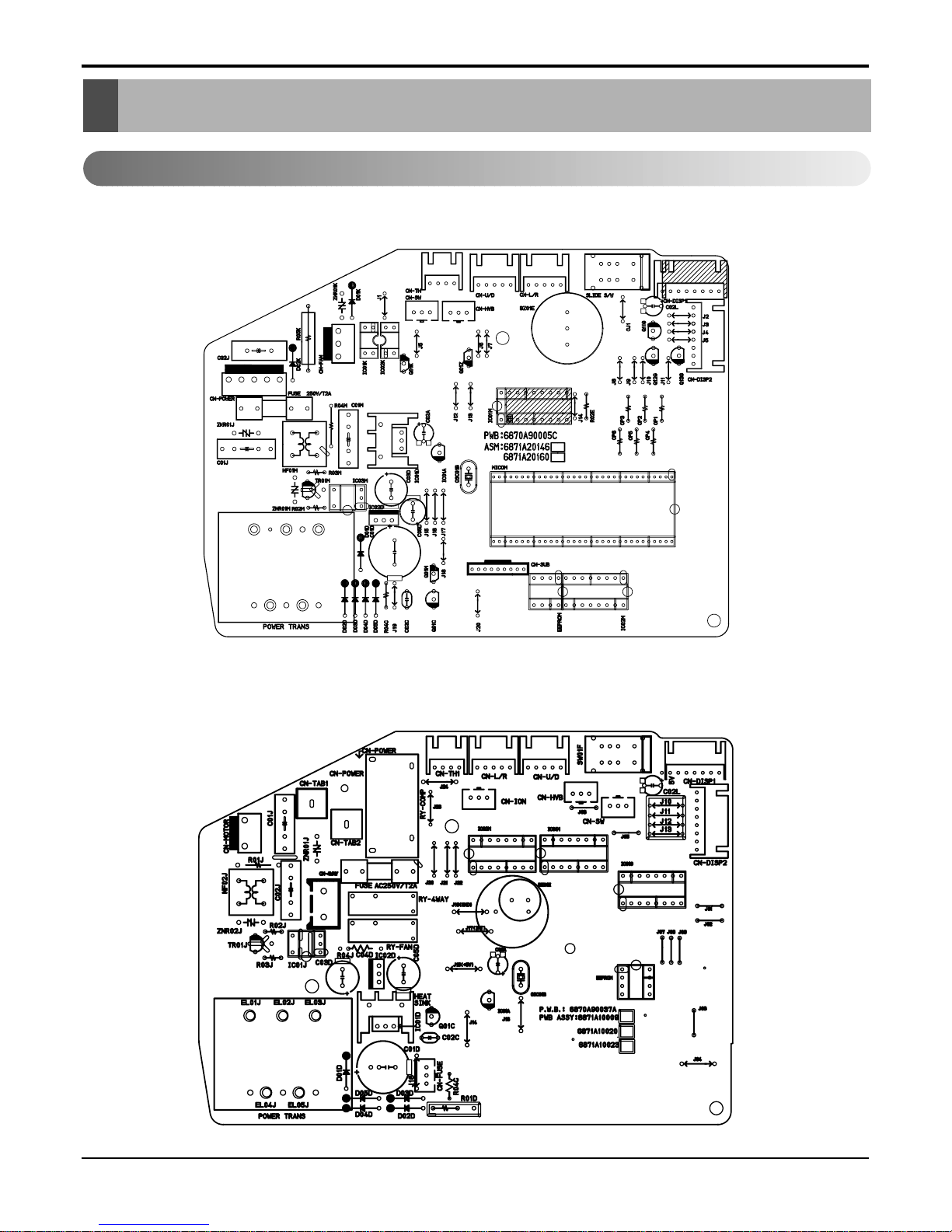
Electronic Control Device
Electronic Control Device
Indoor Unit
• MAIN P.C.B ASM(L3-C362LL0, L3-C482LL0)
• MAIN P.C.B ASM(L2-C362LL0)
18 Multi Air Conditioner
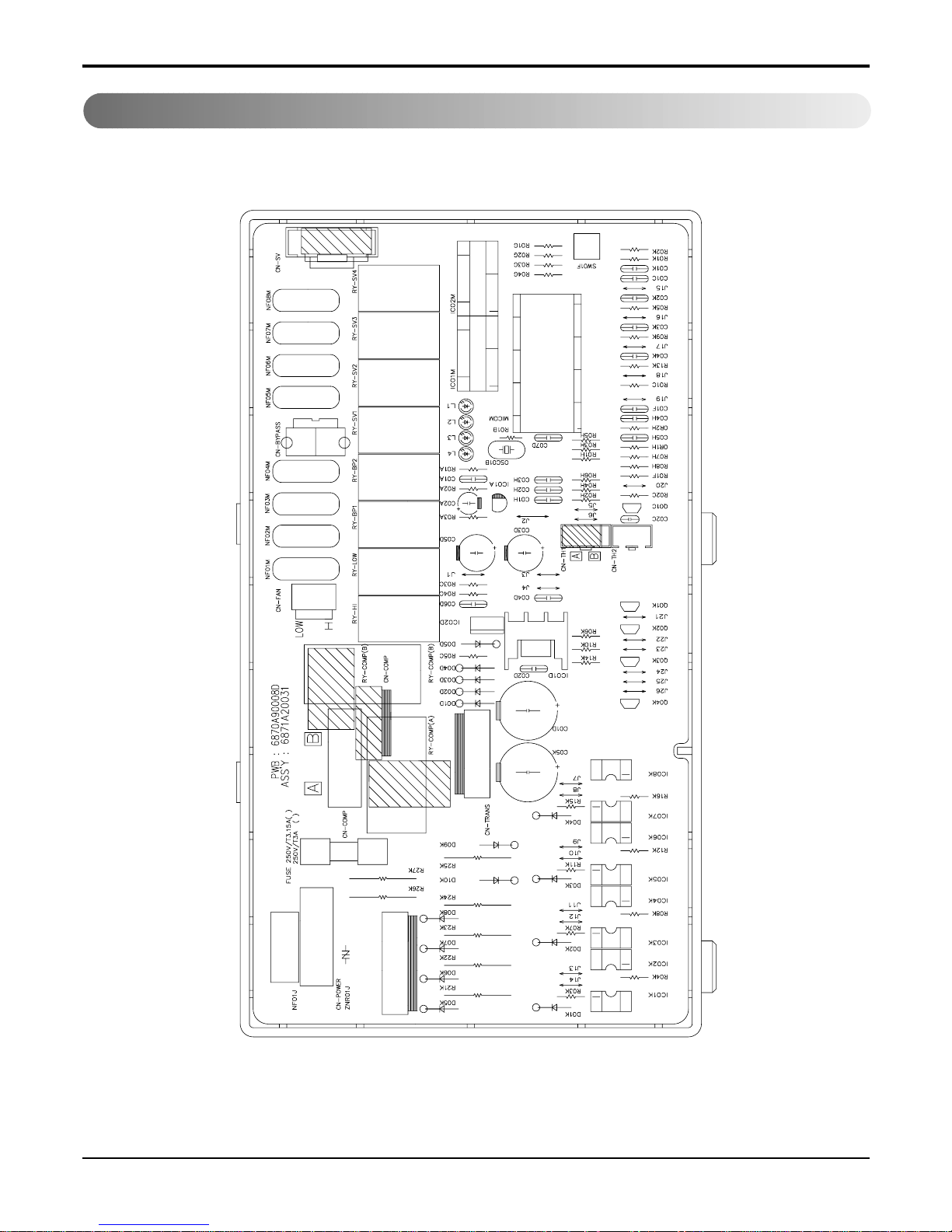
Electronic Control Device
Outdoor Unit
• MAIN P.C.B ASM(L3-C362LL0, L3-C482LL0)
Service Manual 19
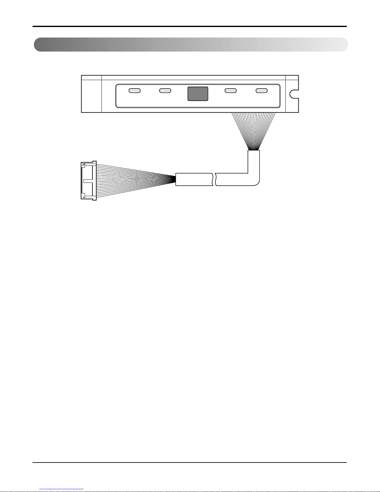
Electronic Control Device
Display P.C.B ASM
20 Multi Air Conditioner
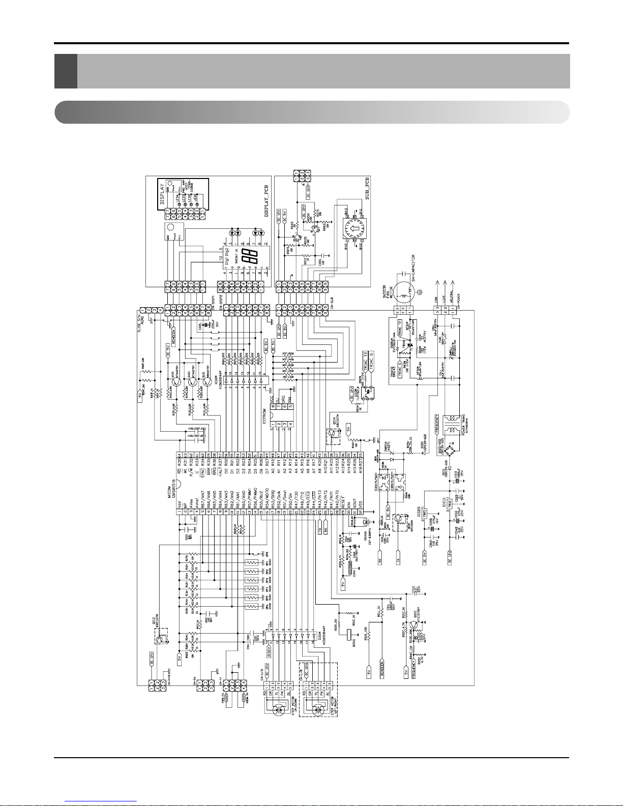
Schematic Diagram
Schematic Diagram
Indoor Unit
• L3-C362LL0, L3-C482LL0
Service Manual 21
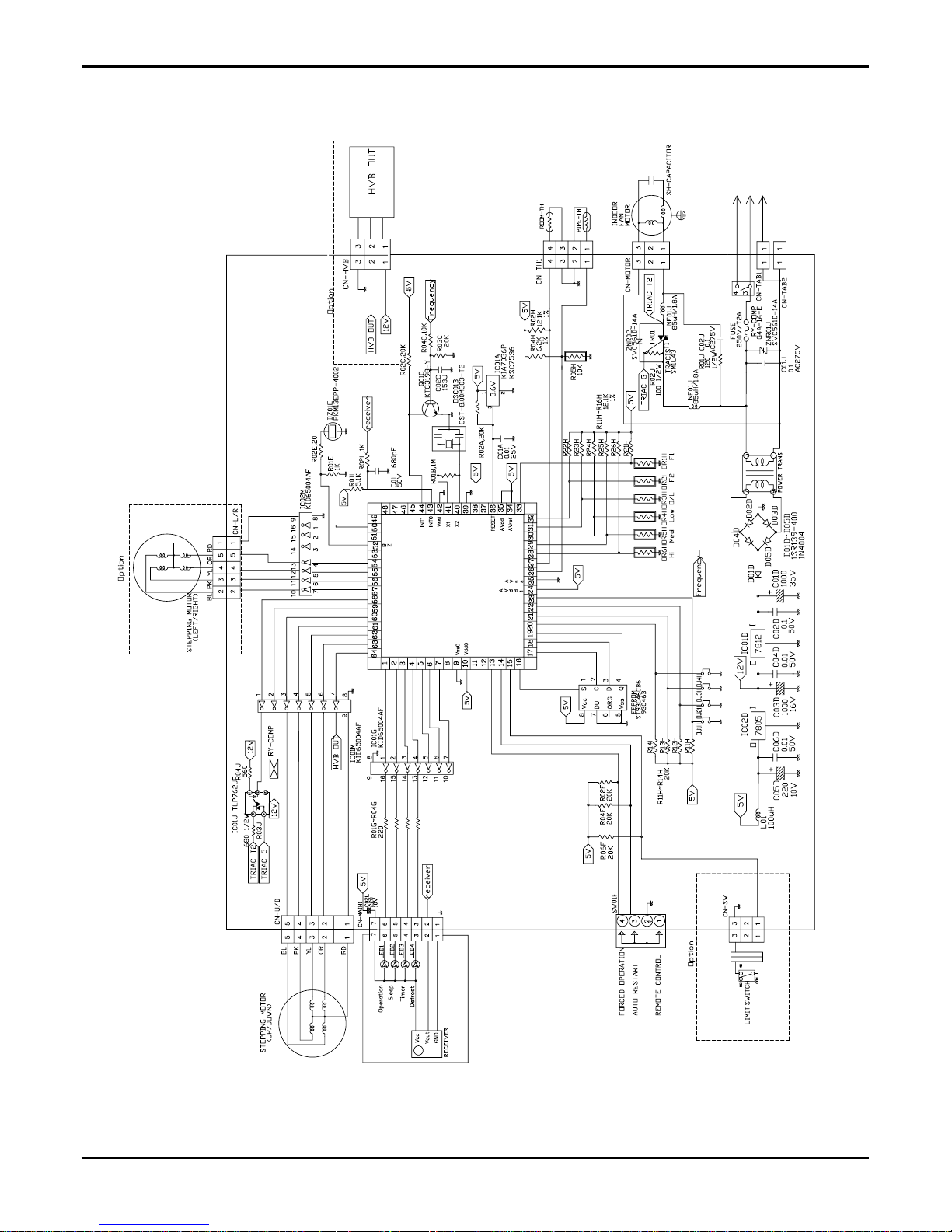
Schematic Diagram
• L2-C362LL0

22 Multi Air Conditioner
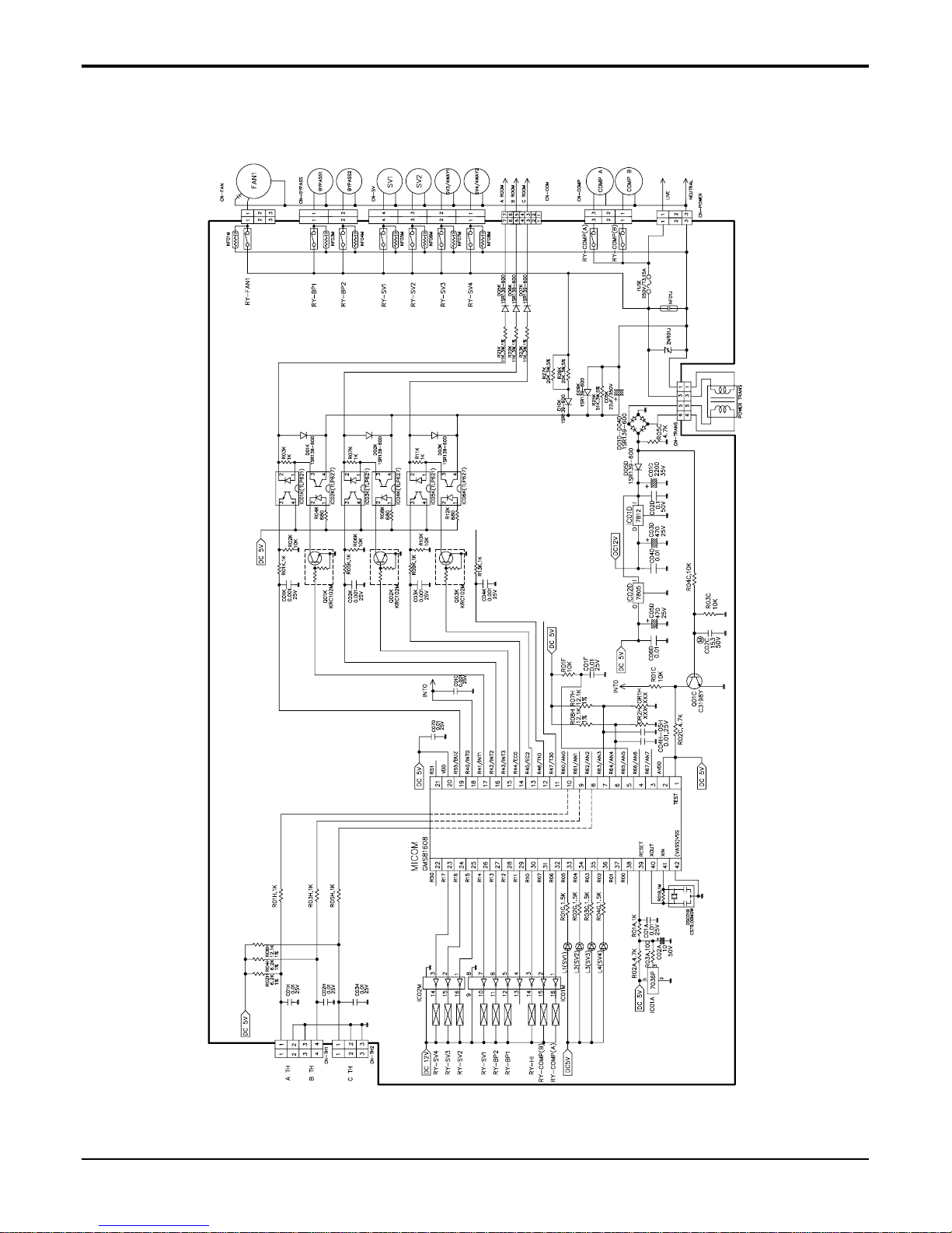
Schematic Diagram
Outdoor Unit
• L3-C362LL0
Service Manual 23
Schematic Diagram
• L3-C482LL0
 Loading...