

LG L26W56S, L26W56B, L26W56W Owner's Manual

© Copyright 2006, LG Electronics U.S.A., Inc.
Installation and Operating Guide | Warranty
Model Numbers | L26W56S • L26W56B • L26W56W | LCD TV/Monitors
page
5
t a b l e o f c o n t e n t s
Zenith and the lightning Z logo are registered
trademarks of Zenith Electronics Corporation
RISK OF ELECTRIC SHOCK
DO NOT OPEN
CAUTION
CAUTION:
TO REDUCE THE RISK OF ELECTRIC SHOCK DO NOT REMOVE COVER (OR BACK). NO USER SERVICEABLE PARTS INSIDE. REFER TO QUALIFIED
SERVICE PERSONNEL.
WARNING:
TO PREVENT FIRE OR SHOCK HAZARDS, DO NOT EXPOSE THIS PRODUCT TO RAIN OR MOISTURE.
THIS PRODUCT MUST BE USED WITH UL LISTED MOUNTING BRACKET.
IT IS FORBIDDEN TO CONNECT THIS TV TO ANY TELECOMMUNICATION NETWORK / TELEPHONE.
The lightning flash with arrowhead symbol, within an equilateral triangle, is intended to alert the user to the
presence of uninsulated “dangerous voltage” within the product’s enclosure that may be of sufficient magnitude
to constitute a risk of electric shock to persons.
The exclamation point within an equilateral triangle is intended to alert the user to the presence of important
operating and maintenance (servicing) instructions in the literature accompanying the appliance.
NOTE TO CABLE TV INSTALLER:
This reminder is provided to call the CATV system installer’s attention to Article 820-40 of the National Electric Code (U.S.A.). The code
provides guidelines for proper grounding and, in particular, specifies that the cable ground shall be connected to the grounding system of
the building, as close to the point of the cable entry as practical.
REGULATORY INFORMATION:
This equipment has been tested and found to comply with the limits for a Class B digital device, pursuant to Part 15 of the FCC Rules.
These limits are designed to provide reasonable protection against harmful interference when the equipment is operated in a residential
installation. This equipment generates, uses and can radiate radio frequency energy and, if not installed and used in accordance with the
instruction manual, may cause harmful interference to radio communications. However, there is no guarantee that interference will not
occur in a particular installation. If this equipment does cause harmful interference to radio or television reception, which can be
determined by turning the equipment off and on, the user is encouraged to try to correct the interference by one or more of the following
measures:
•Reorient or relocate the receiving antenna.
•Increase the separation between the equipment and receiver.
•Connect the equipment into an outlet on a circuit different from that to which the receiver is connected.
•Consult the dealer or an experienced radio/TV technician for help.
Marketed and Distributed in the United States by LG Electronics U.S.A., Inc.
2000 Millbrook Drive, Lincolnshire, IL 60069.
For Customer Support/Service please call:
1-888-865-3026
www.zenith.com
www.lgcommercial.com
RECORD THE MODEL NUMBER
The model and serial number of this LCD TV/Monitor are
located on the back of the cabinet. For future reference,
we suggest that you record the serial number here:
MODEL NO. L26W56S, L26W56B, L26W56W
SERIAL NO.____________________________________

PAGE 3
CAUTION:
Do not attempt to modify this product in any way without written authorization from Zenith Electronics Corporation.
Unauthorized modification could void the user’s authority to operate this product.
COMPLIANCE:
The responsible party for this product’s compliance is:
LG Electronics U.S.A., Inc.,
2000 Millbrook Drive
Lincolnshire, IL 60069, USA.
Phone: 1-847-941-8000
WARNING:
Apparatus shall not be exposed to dripping or splashing and no objects filled with liquids, such as vases, shall not be placed on the
apparatus.
CAUTION:
THESE SERVICING INSTRUCTIONS ARE FOR USE BY QUALIFIED SERVICE PERSONAL ONLY. TO REDUCE THE RISK OF ELECTRIC
SHOCK, DO NOT PERFORM ANY SERVICING OTHER THAN THAT CONTAINED IN THE OPERATING INSTRUCTIONS UNLESS YOU ARE
QUALIFIED TO DO SO.
CAUTION:
When used outside of the U.S., it may be used HAR cord with fitting of an approved agency is employed.
(When used outside of U.S., other power supply cords may be used if the cord is approved by the local regulating agency.)
IMPORTANT SAFEGUARDS FOR YOU AND YOUR NEW PRODUCT
YOUR PRODUCT HAS BEEN MANUFACTURED AND TESTED WITH YOUR SAFETY IN MIND. HOWEVER, IMPROPER USE CAN RESULT IN
POTENTIAL ELECTRICAL SHOCK OR FIRE HAZARDS. TO AVOID DEFEATING THE SAFEGUARDS THAT HAVE BEEN BUILT INTO YOUR NEW
PRODUCT, PLEASE READ AND OBSERVE THE FOLLOWING SAFETY POINTS WHEN INSTALLING AND USING YOUR NEW PRODUCT, AND SAVE
THEM FOR FUTURE REFERENCE. OBSERVING THE SIMPLE PRECAUTIONS DISCUSSED IN THIS MANUAL CAN HELP YOU GET MANY YEARS OF
ENJOYMENT AND SAFE OPERATION THAT ARE BUILT INTO YOUR NEW PRODUCT.
Notes
- If the TV feels cold to the touch, there may be a small “flicker” when it is turned on. This is normal, there is nothing
wrong with the TV.
- Some minute dot defects may be visible on the screen, appearing as tiny red, green, or blue spots. However, they have no
adverse effect on the TVs performance.
- Avoid touching the LCD screen or holding your finger(s) against it for long periods of time. Doing so may produce some
temporary distortion effects on the screen.
PAGE 4
1. Read these instructions.
2. Keep these instructions.
3. Heed all warnings.
4. Follow all instructions.
5. Do not use this apparatus near water.
6. Clean only with dry cloth.
7. Do not block any ventilation openings. Install in accordance with the manufacturer’s instructions.
8. Do not install near any heat sources such as radiators, heat registers, stoves, or other apparatus (including amplifiers) that
produce heat.
9. Do not defeat the safety purpose of the polarized or grounding-type plug. A polarized plug has two blades with one wider
than the other. A grounding type plug has two blades and a third grounding prong. The wide blade or the third prong is
provided for your safety. If the provided plug does not fit into your outlet, consult an electrician for replacement of the
obsolete outlet.
10. Protect the power cord from being walked on or pinched particularly at plugs, convenience receptacles, and the point where
they exit from the apparatus.
11. Only use attachments/accessories specified by the manufacturer.
12. Use only with the cart, stand, tripod, bracket, or table specified by the manufacturer, or sold with the apparatus. When a cart
is used, use caution when moving the cart/apparatus combination to avoid injury from tip-over.
13. Unplug this apparatus during lightning storms or when unused for long periods of time.
14. Refer all servicing to qualified service personnel. Servicing is required when the apparatus has been damaged in any way,
such as power-supply cord or plug is damaged, liquid has been spilled or object have fallen into the apparatus, the apparatus
has been exposed to rain or moisture, does not operate normally, or has been dropped.
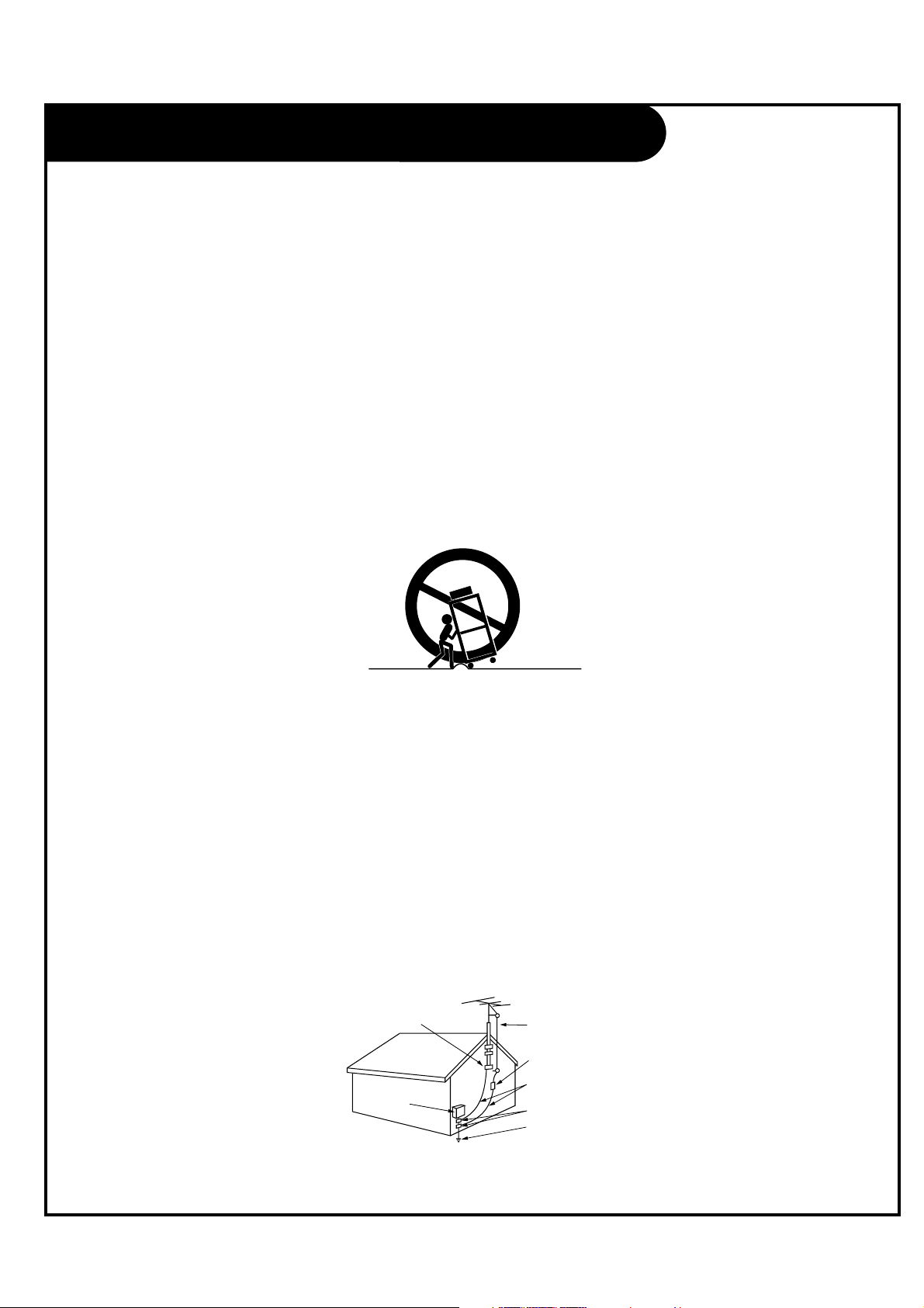
Outdoor Antenna Grounding
If an outside antenna or cable system is connected to the product, be sure the antenna or cable system is grounded so as to
provide some protection against voltage surges and built-up static charges. Article 810 of the National Electrical Code (U.S.A.),
ANSI/NFPA 70 provides information with regard to proper grounding of the mast and supporting structure, grounding of the
lead-in wire to an antenna discharge unit, size of grounding conductors, location of antenna-discharge unit, connection to
grounding electrodes, and requirements for the grounding electrode.
Example of Grounding According to National Electrical Code Instructions
IMPORTANT SAFETY INSTRUCTIONS
Antenna Lead in Wire
Antenna Discharge Unit
(NEC Section 810-20)
Grounding Conductor
(NEC Section 810-21)
Ground Clamps
Power Service Grounding
Electrode System (NEC
Art 250, Part H)
Ground Clamp
Electric Service
Equipment
NEC - National Electrical Code
PORTABLE CART WARNING
Table of Contents
PAGE 5
Safety Warnings . . . . . . . . . . . . . . . . . . . . . . . . . .2-3
Important Safety Instructions . . . . . . . . . . . . . . . . . . .4
Table of Contents . . . . . . . . . . . . . . . . . . . . . . . . . . .5
Step 1. LCD TV/Monitor Installation and Connections
Setup Checklist . . . . . . . . . . . . . . . . . . . . . . . . . . . .6
Installation/Connections Overview . . . . . . . . . . . . . . . .7
VESA Standard TV Mounts . . . . . . . . . . . . . . . . . . . . . .8
TV and other Equipment Hookup
Antenna . . . . . . . . . . . . . . . . . . . . . . . . . . . . . . . . .9
Cable Service . . . . . . . . . . . . . . . . . . . . . . . . . . . . .10
Antenna & VCR . . . . . . . . . . . . . . . . . . . . . . . . . . . .11
Cable Service with VCR . . . . . . . . . . . . . . . . . . . . . .12
S-Video (DVD-VCR) . . . . . . . . . . . . . . . . . . . . . . . . .13
Component Video (DVD) . . . . . . . . . . . . . . . . . . . . . .13
DVI Hookup To RJP100 or DVD Player . . . . . . . . . . . . .14
Computer PC Hookup . . . . . . . . . . . . . . . . . . . . . . . .14
AC Power Cord Connection . . . . . . . . . . . . . . . . . . . .15
Front Panel Controls . . . . . . . . . . . . . . . . . . . . . . . 16
Menus and Displays Overview
On-Screen Menus Overview . . . . . . . . . . . . . . . . . . . .17
Other Menus and On-Screen Displays . . . . . . . . . . . . . .18
User Remote Control Key Functions . . . . . . . . . . . . . . .19
Installer Remote Key Functions . . . . . . . . . . . . . . . . .20
Step 2. Channel Search and Reception Setup
Auto Program (Do a Channel Search) . . . . . . . . . . .21
Channel Menu
Channel List . . . . . . . . . . . . . . . . . . . . . . . . . . . . . 22
Channel Labels Setup . . . . . . . . . . . . . . . . . . . . . . . 23
Step 3. Customize the TV’s Features
Setup Menu
Clock Setup . . . . . . . . . . . . . . . . . . . . . . . . . . . . .24
Menu Language . . . . . . . . . . . . . . . . . . . . . . . . . . .27
V-Chip . . . . . . . . . . . . . . . . . . . . . . . . . . . . . . .28-31
Caption Menu . . . . . . . . . . . . . . . . . . . . . . . . . . . .32
Sound Menu . . . . . . . . . . . . . . . . . . . . . . . . . . 34-35
Picture Menu . . . . . . . . . . . . . . . . . . . . . . . . . .36-37
Installer Overview . . . . . . . . . . . . . . . . . . . . . . . . .38
Commercial Mode Setup . . . . . . . . . . . . . . . . . . . . . .39
Reference . . . . . . . . . . . . . . . . . . . . . . . . . . . . .49-56
Troubleshooting . . . . . . . . . . . . . . . . . . . . . . . . .56-57
Glossary of Terms . . . . . . . . . . . . . . . . . . . . . . . . . .59
Commercial Mode Check . . . . . . . . . . . . . . . . . . . . . .58
Warranty . . . . . . . . . . . . . . . . . . . . . . . . . Back Cover
The table of contents lists the pages to go to for setting up the features for the end user.
Optional Installer Remote Control for Model No. L26W56X
Shown herein is an optional Installer remote control available for the L26W56X model only. The
remote control is NOT included with the LCD TV/Monitor. However, the user's remote is included with
the TV.
Purchase the Optional Installer's Remote and Clone Programmer
To perform a normal installation set up, you need an installer's remote such as the one shown, and the LT2002 Quickset II
Clone Programmer – both are shown and described in later sections. See your Zenith dealer if you wish to purchase the
Installer remote and LT2002. The installer remote allows access to the Installer menus, User menus, and Channel Banks in
the Manual Channel Set options on the Setup menu. The installer remote has Menu, Select, and Adjust Keys. The LT2002
Quickset II Clone Programmer is used to duplicate a TV's setup and install it on another identical TV.
Note: Design and specifications are subject to change without prior notice.

PAGE 6
Installation Overview
• Unpack the LCD TV/Monitor and all
accessories.
• Determine installation location for the
LCD TV/Monitor, TV stand or mount.
• Determine mounting and installation
requirements. If used, AC Power
source outlet, Antenna/Cable service
connectors, any external equipment
required for system or TV operation,
all necessary cables, wires, connectors
and any other additional required
hardware, etc.
Installation Overview & System Setup:
Questions to Consider Before
Installation
VESA Bracket
Does the VESA Bracket have to be
mounted to the TV? Y: Install VESA
Bracket on TV following the instructions
supplied with the bracket.
Yes___ No___
TV Stand
Does the TV have to be mounted on the
stand? Y: Mount the TV on the stand
following the instructions provided with
the TV stand.
Yes___ No___
Installer's Remote Control
Does the Installer have an the optional
Installer's remote control available to
use to set up the TV (This is a must for
TV setup.)?
Yes___ No___
Master TV Setup
Will the Master TV's features setup be
cloned and be copied to other identical
LCD TV/Monitors?
Yes___ No___
LT2002 Quickset II Clone Programmer
To copy the TV's setup, the installer will
need a clone programmer. Is there a
Zenith LT2002 Clone Programmer
available?
Yes___ No___
End-User Remote Control
Will a remote control be provided to the
end user to operate the TV? (The remote
is included with the TV.)
Yes___ No___
End-User Menu Access
Will the end-user have access to all the
menus on the TVs from the front panel?
Yes___ No___
LCD TV/Monitor Setup Checklist
1. Install the LCD TV/Monitor where it
will be used.
Prior to Operation
The LCD TV/Monitor must be connected
to all external antenna/cable, video, and
audio source equipment and a DC power
source. See page 5, Table of Contents.
2. Make all external source equipment
connections. See pages 10 - 15.
3. Connect the LCD TV/Monitor to a
standard 120V, 60 Hertz, AC power
source. See page 15.
4. Turn on the TV and all source
equipment.
Review TV Setup Options in the
Installer's Menu Section
The Installer's menu includes a number
of options for the master TV's setup that
enable the installer or system
administrator to devise a unique system
using the many different options and
variables available. See Installer's menus
section.
Master TV Features Setup for Cloning
Overview
• Set up Installer's remote control, see
page 20.
• Select Tuning Band and do Channel
Search, see page 21.
• Channel List.
• Channel Label.
• Video/picture appearance options
setup, see Picture menu.
• Audio/sound options setup, see Sound
menu.
• Set up all other features. See page 5,
Table of Contents, for a list of features
available on this LCD TV/Monitor.
Clone Master TV's Setup
See Clone Programmer section.
Setup Checklist
DVI/PC AUDIOINHDMI/DVI
IN
RS-232C
PC IN
UPDATE
DIGTAL AUDIO
OUT(OPTICAL)
S-VIDEO
IN
RS-232C
SELECT
NORMAL
(DTV)
CONTROL
AUDIO IN VIDEO IN VIDEO IN
VIDEO IN
VIDEO IN
VIDEO 3
AUDIO IN
VIDEO 3/ S-VIDEO
VIDEO 1
AUDIO IN
COMPONENT(DVD/DTV)1
COMPONENT(DVD/DTV)2
AUDIO IN
M.P.I
ANTENNA
CABLE
RJP
INTERFACE
FUTURE
USE
AC IN
PAGE 7
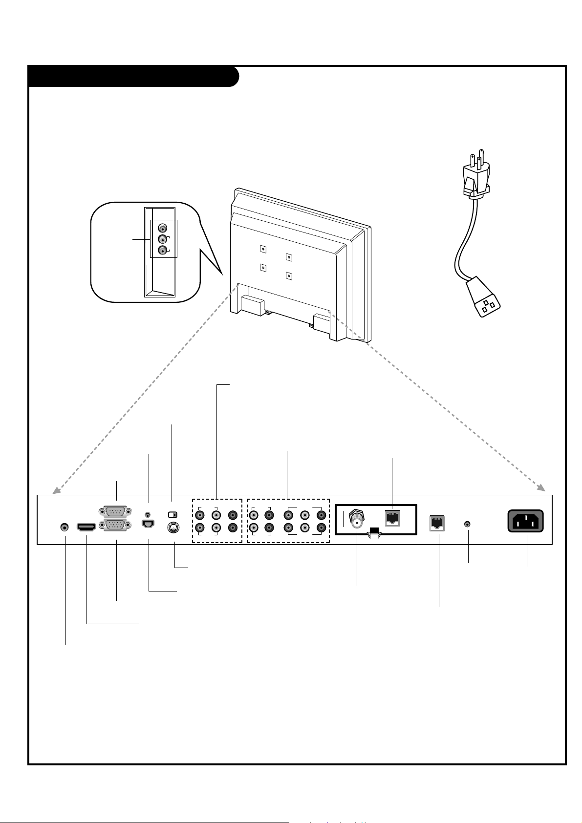
M.P.I. INTERFACE
Use with clone programmer.
FUTURE USE
DVI/PC AUDIO IN
PC IN
HDMI/DVI IN
DIGITAL AUDIO OUT
(Optical)
RS-232C PORT
RS-232C SELECT
SWITCH
UPDATE
SWITCH
ANTENNA CABLE
Connect to an antenna or
cable system.
S-VIDEO IN
AUDIO / VIDEO 1, 3 IN
Connect Audio / Video
equipment to these jacks.
COMPONENT 1, 2 IN
AC IN
RJP INTERFACE
To hook up source equipment, see below and also refer to the Table of
Contents on page 5; shows pages to go to for equipment hookup options.
VIDEO2(SIDE AUTO-CAMPORT)
VIDEO IN AUDIO IN
LR
AUDIO/
VIDEO 2
(SIDE AUTOCAMPORT)
Note : RS-232C, Update Switch and RS-232C Select Switch are reserved for qualified and
authorized service and technical support personal only.
Installation/Connections Overview
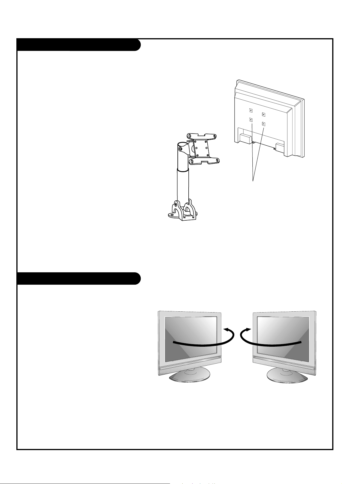
VESA Standard TV Mounts
PAGE 8
Swivel Stand
- The TV can be conveniently
swiveled on its stand 30° to
the left or right to provide
optimum viewing angles.
There are several Vesa standard
mounts available that can be used
with this TV. The mount shown to the
right would be installed on the TV
back using required bolts in the four
pre-threaded holes provided.
Follow any instructions supplied with
the Vesa mount if one is to be used
for the TV installation.
TV Swivel Stand
Vesa Standard
Mounting Holes
Typical
Vesa
Mount
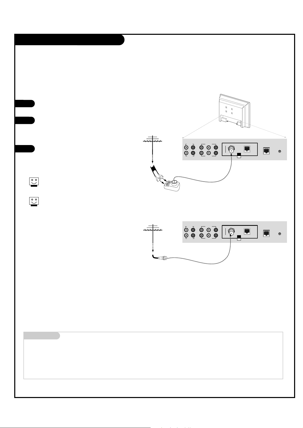
Antenna Hookup
PAGE 9
VIDEO IN
VIDEO IN
AUDIO IN
COMPONENT(DVD/DTV)1
COMPONENT(DVD/DTV)2
AUDIO IN
M.P.I
ANTENNA
CABLE
RJP
INTERFACE
FUTURE
USE
VIDEO IN
VIDEO IN
AUDIO IN
COMPONENT(DVD/DTV)1
COMPONENT(DVD/DTV)2
AUDIO IN
M.P.I
ANTENNA
CABLE
RJP
INTERFACE
FUTURE
USE
Mini glossary
75 OHM RF CABLE The wire that comes from an off-air antenna or cable service provider. Each end looks like a hex shaped nut with a wire sticking
through the middle, and it screws onto the threaded jack on the back of the TV.
A small device that connects a two-wire 300 ohm antenna to a 75 ohm RF jack. They are usually about an inch long with two screws
on one end and a round opening with a wire sticking out on the other end.
1
2
3
RF Coaxial Wire
(75 ohm)
300/75 ohm
Adapter
Connections Panel
Connections Panel
Locate the Antenna/Cable jack on the back
of the LCD TV/Monitor.
Connect the antenna wire (Flat or Round)
that runs from the wall to this jack,
according to one of the diagrams shown to
the right.
After all connections are complete, plug in
the TV. The LCD TV/Monitor is designed to
operate on AC power.
Flat Wire
(300 ohm)
Connect an off-air antenna to the LCD TV/Monitor.
If the antenna is a 75 ohm RF cable, then no
adapters are required.
A 300 to 75 ohm adapter is not included with
the Zenith LCD TV/Monitor.
300 TO 75 OHM
ADAPTER
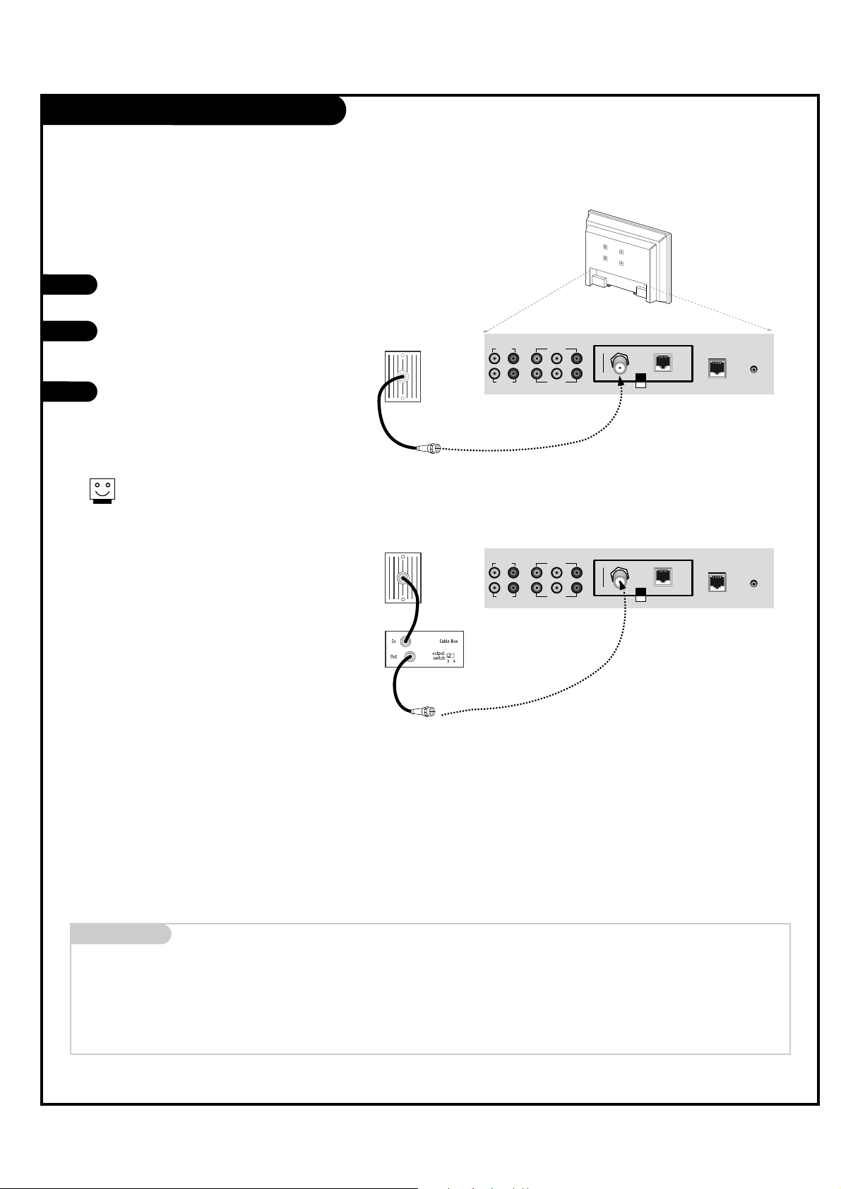
Cable Service Hookup
PAGE 10
VIDEO IN
VIDEO IN
AUDIO IN
COMPONENT(DVD/DTV)1
COMPONENT(DVD/DTV)2
AUDIO IN
M.P.I
ANTENNA
CABLE
RJP
INTERFACE
FUTURE
USE
VIDEO IN
VIDEO IN
AUDIO IN
COMPONENT(DVD/DTV)1
COMPONENT(DVD/DTV)2
AUDIO IN
M.P.I
ANTENNA
CABLE
RJP
INTERFACE
FUTURE
USE
Locate the Antenna/Cable jack on the
back of the TV.
Connect the cable wire to the
Antenna/Cable jack according to one
of the diagrams to the right.
After all connections are complete,
plug in the TV. The LCD TV/Monitor is
designed to operate on AC power.
1
2
3
Connections Panel
Cable TV
Wall Jack
RF Coaxial Wire
(75 ohm)
Cable TV
Wall Jack
Coaxial Wire
RF (75 ohm)
Connections Panel
Connect cable service to the LCD TV/Monitor.
Mini glossary
75 OHM RF CABLE The wire that comes from an off-air antenna or cable service provider. Each end looks like a hex shaped nut with a wire sticking
through the middle, and it screws onto the threaded jack on the back of the TV.
A small device that connects a two-wire 300 ohm antenna to a 75 ohm RF jack. They are usually about an inch long with two screws
on one end and a round opening with a wire sticking out on the other end.
300 TO 75 OHM
ADAPTER
For cable box operation, leave the television
tuned to channel three or four and use the
cable box to change channels.
Antenna & VCR Hookup
UPDATE
DIGTAL AUDIO
OUT(OPTICAL)
S-VIDEO
IN
RS-232C
SELECT
NORMAL
(DTV)
CONTROL
AUDIO IN VIDEO IN VIDEO IN
VIDEO IN
VIDEO IN
VIDEO 3
AUDIO IN
VIDEO 3/ S-VIDEO
VIDEO 1
AUDIO IN
COMPONENT(DVD/DTV)1
COMPONENT(DVD/DTV)2
AUDIO IN
M.P.I
ANTENNA
CABLE
VCR Back
PAGE 11
300/75ohm
Adapter
VCR Back Panel
Round
or
Flat wire
(300 ohm)
Locate the Antenna/Cable jack on
the back of the VCR.
Connect the antenna wire that runs
from the wall jack to the VCR.
Connect other wires according to
the diagram to the right.
After all connections are complete,
plug in the TV. The LCD TV/Monitor
is designed to operate on AC power.
1
2
3
Connect antenna and a VCR to the LCD TV/Monitor.
Connections Panel
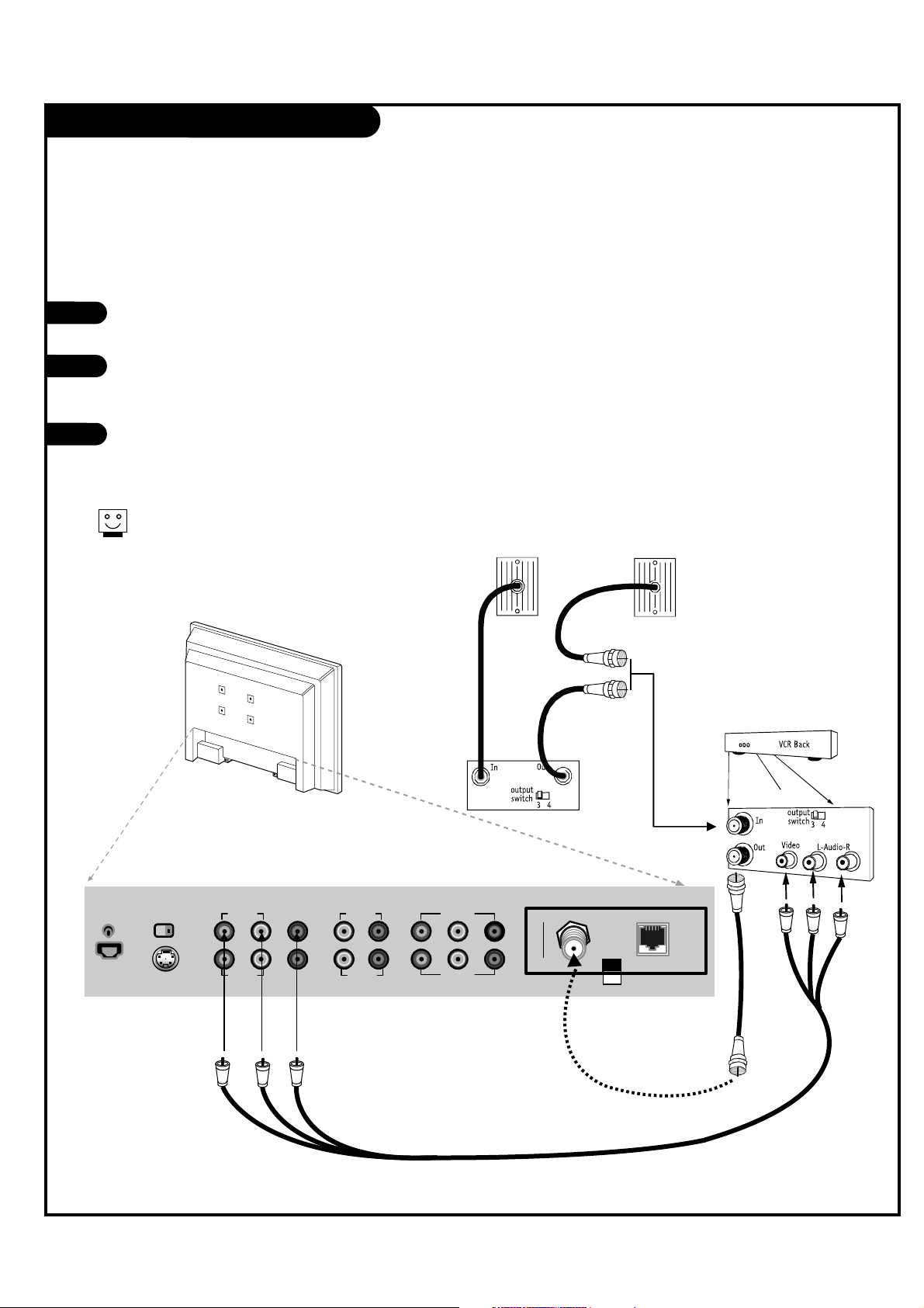
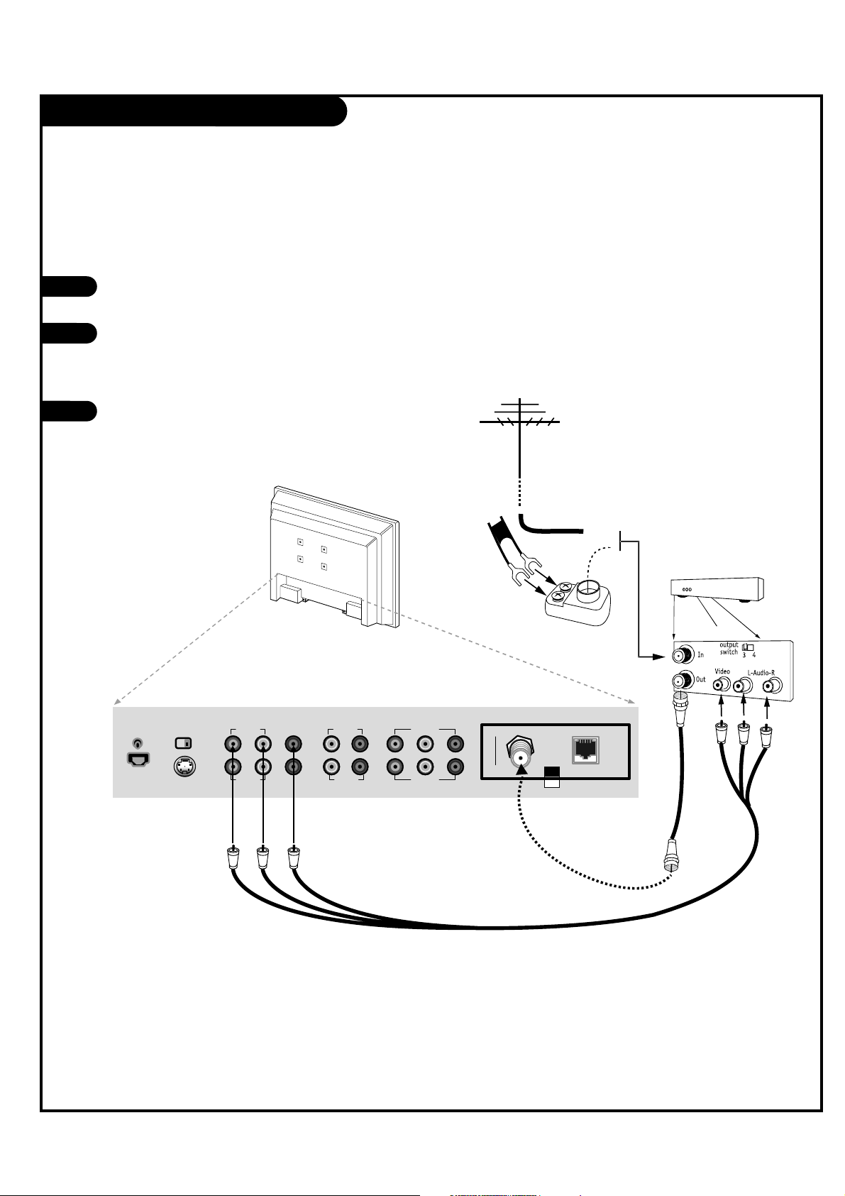
Cable Service with VCR Hookup
PAGE 12
Locate the Antenna/Cable jack on the
back of the VCR.
Connect the cable service wire to the VCR.
Connect other wires according to the
diagram to the right.
After all connections are complete, plug
in the TV. The LCD TV/Monitor is designed
to operate on AC power.
1
2
3
UPDATE
DIGTAL AUDIO
OUT(OPTICAL)
S-VIDEO
IN
RS-232C
SELECT
NORMAL
(DTV)
CONTROL
AUDIO IN VIDEO IN VIDEO IN
VIDEO IN
VIDEO IN
VIDEO 3
AUDIO IN
VIDEO 3/ S-VIDEO
VIDEO 1
AUDIO IN
COMPONENT(DVD/DTV)1
COMPONENT(DVD/DTV)2
AUDIO IN
M.P.I
ANTENNA
CABLE
Cable Box
Cable TV
Wall Jack
Cable TV
Wall Jack
Connections Panel
VCR AV Panel
Connect cable service and a VCR to the LCD TV/Monitor.
For cable box operation, leave the VCR
and the television tuned to channel
three or four and use the cable box to
change channels.
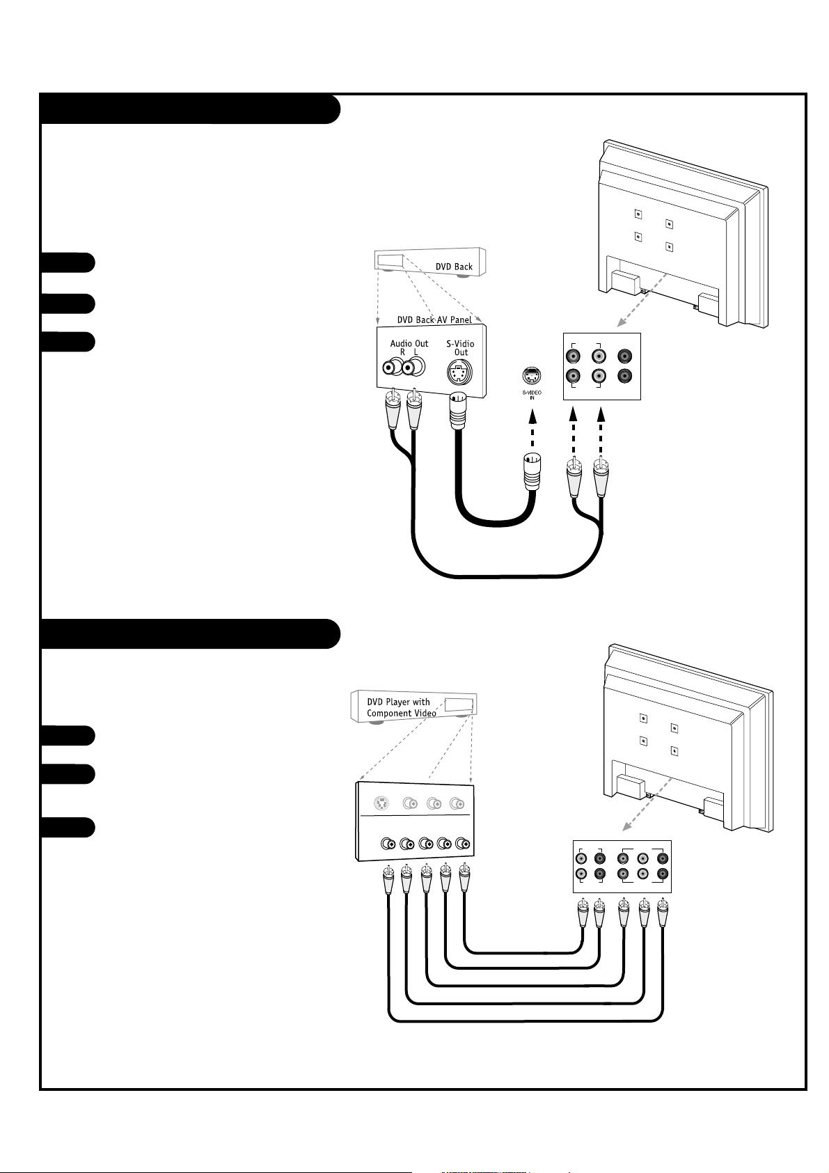
S-Video Hookup (DVD-VCR)
Component Video Hookup (DVD)
PAGE 13
Locate the S-Video out port on the DVD
or VCR.
Connect an S-Video cable between the
DVD player and S-Video In on the TV.
Make R - L Audio connections as indicated
to the right.
After all connections have been made,
select the S-Video source to display the
DVD image on the TV.
1
2
3
Locate the component out jacks on
the DVD player.
Connect component video cables
between the DVD player and
Component 1 or 2 In on the TV.
Make R - L Audio connections as
indicated to the right.
After all connections have been made,
select the Component 1 or 2 source to
display the DVD image on the TV.
1
2
3
AUDIO IN
VIDEO IN
VIDEO IN
VIDEO 3
AUDIO IN
VIDEO 3/ S-VIDEO
VIDEO 1
VIDEO IN
VIDEO IN
AUDIO IN
COMPONENT(DVD/DTV)1
COMPONENT(DVD/DTV)2
R L Pr Pb Y
AUDIO IN
CO
M
PO
NEN
T
VIDEO
O
UT
Y
P
B PR
RL
S-VID
EO O
UT
VIDEO
R-AUD
IO
L-/MONO
S-Video/R-L Audio
cables are not included
with TV
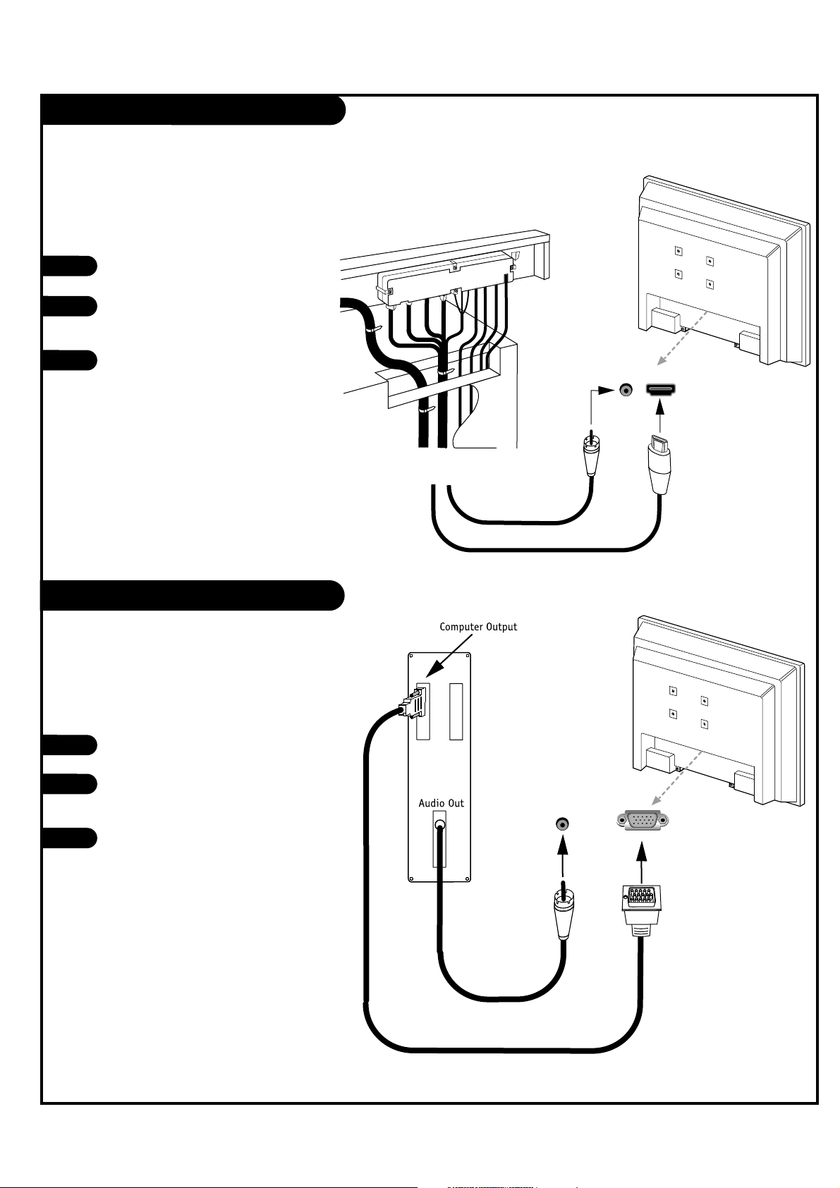
DVI Hookup To RJP100 or DVD Player
PAGE 14
Computer PC Hookup
Locate the DVI out port on
the RJP100M or DVI device.
Connect a DVI cable
between the RJP100M and
DVI in port on the TV.
If required, make Audio
connections as indicated to
the right.
After all connections have
been made, select the DVI
source to display the DVI
image on the TV.
1
2
3
Locate the computer out port
on the computer.
Connect a computer cable
between the computer and PC
In on the TV.
Make PC Audio connections as
indicated to the right.
After all connections have
been made, select the PC
source to display the PC image
on the TV.
1
2
3
DVI/PC AUDIOINHDMI/DVI
IN
...
..
.....
DVI/PC AUDIO
IN
PC IN
Back of
Computer
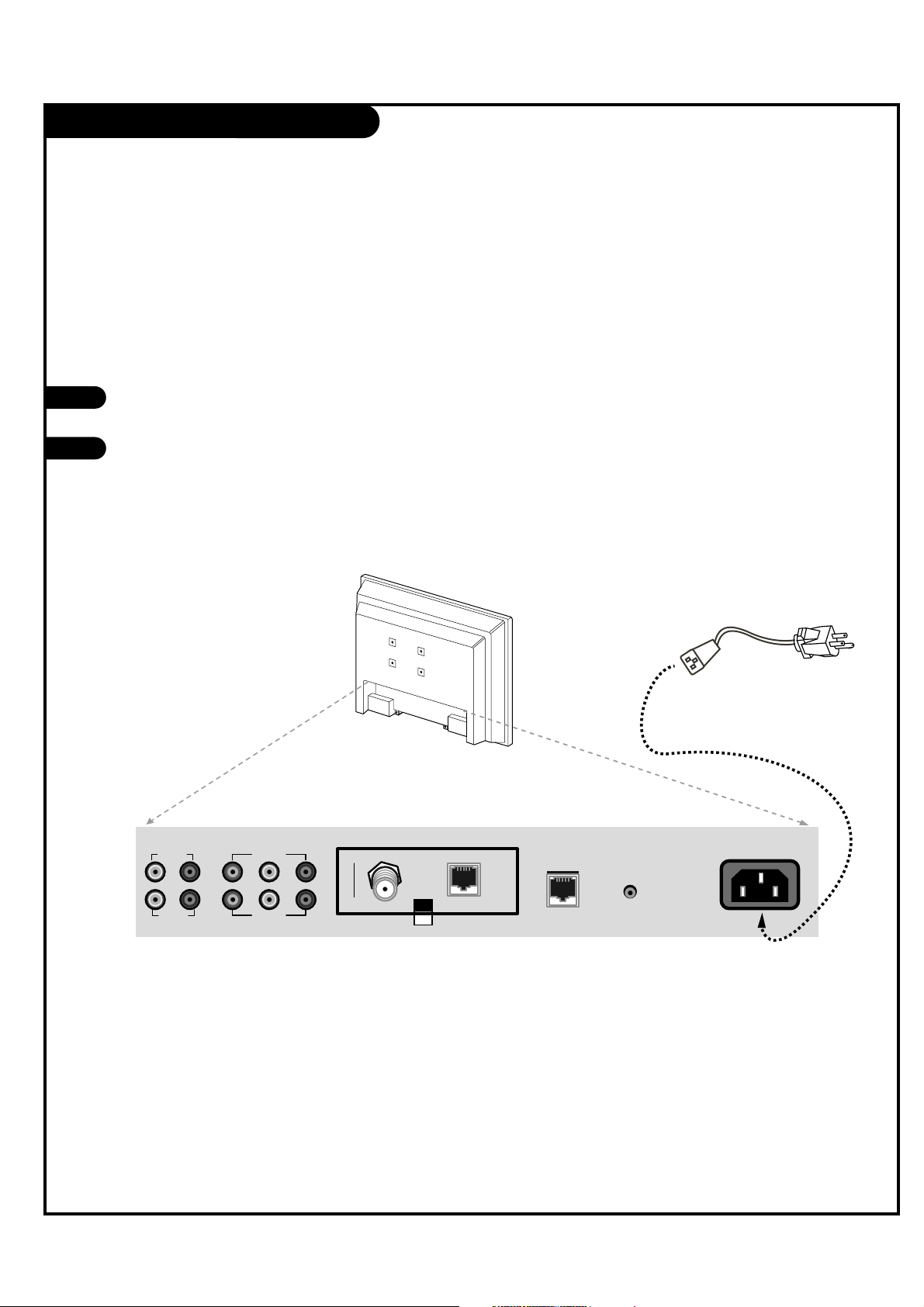
AC Power Cord Connection
PAGE 15
AC Power Cord Hookup
The LCD TV/Monitor is designed to operate on
120V AC power.
Locate the AC Power Cord input socket on the
back of the LCD TV/Monitor.
Insert the AC power cord connector into the
AC Socket on the TV as shown below.
1
2
Connect the AC power cord directly to the LCD TV/Monitor.
AC Power Cord
VIDEO IN
VIDEO IN
AUDIO IN
COMPONENT(DVD/DTV)1
COMPONENT(DVD/DTV)2
AUDIO IN
M.P.I
ANTENNA
CABLE
RJP
INTERFACE
FUTURE
USE
AC IN
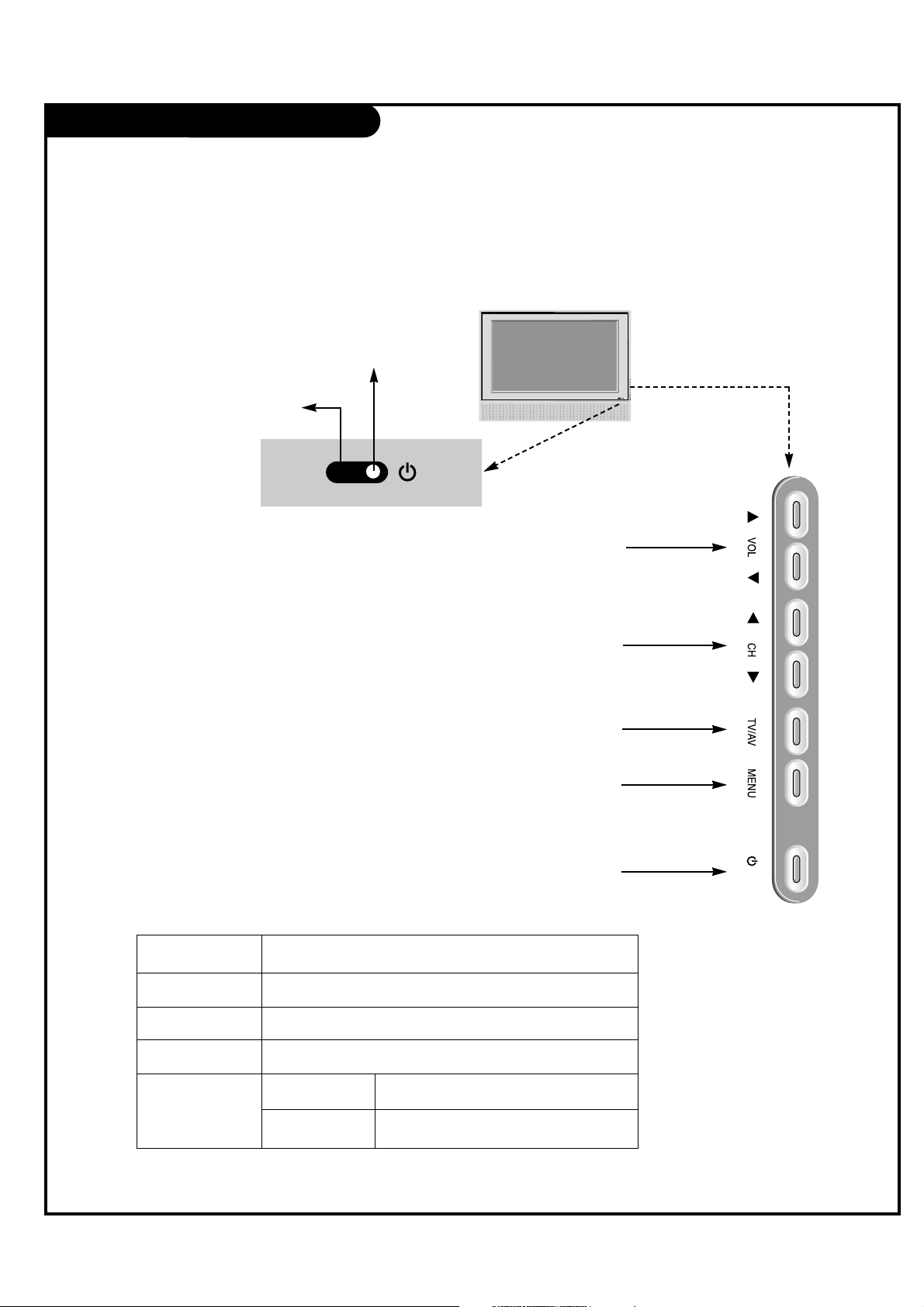
Front Panel Controls
PAGE 16
/ I
TV Operation
Press the POWER button to turn the LCD
TV/Monitor on from standby mode.
Press MENU repeatedly to scroll through menus.
Displays a menu of all available input sources.
Also used to confirm your choice in the onscreen menu.
Use the CH (Channel) Up/Down button to cycle
through the available channels.
Use the VOL (Volume) Up/Down button to adjust
the sound level to your preference.
On-Screen Displays
See descriptions on page 18. On-screen displays
will appear when the feature is active or the
function is being used.
Remote Control Sensor
Power / Standby Indicator
Glows red in Standby mode.
Glows green when the TV is
turned on.
Glows orange in Sleep Timer
and/or Alarm mode.
A
B
C
D
E
Using the front control panel to operate the LCD TV/Monitor.
A
B
C
D
E
LED Color Action/Status
RED Power is Off (Standby)
GREEN is flashing Power On sequence is processing
GREEN Power is On
ORANGE If Power is Off On Timer is set or Alarm is set
If Power is On Off Timer is set or Sleep Timer is set

On-Screen Menus Overview
PAGE 17
ON-SCREEN MENUS
CHANNEL MENU Adjusts the basic operational features of the TV.
Auto Program 21 Automatically finds and stores active channels to scroll through using Channel Up/Down.
Channel List 22 Manually picks and chooses which active channels will appear when using Channel Up/Down
Channel Label 23 Labels the channels with their network names (ABC, CBS, HBO, etc.).
Fine Tune Automatically adjusts the picture for optimum appearance.
Signal Strength Reveals the strength of the incoming digital signal.
SETUP MENU
Time 24 Sets the time.
V-Chip 28 Sets up restrictions or changes the password for Parental Control.
PC
Menu Language 27 Picks the language the on-screen menus will appear in.
Menu Transparency Selects the degree of menu opacity.
Set ID Specifies the TVs identity
CAPTION MENU 32 Chooses analog and digital captioning options.
SOUND MENU 34 Sets up the sound.
Options are: Mode, Balance, Digital Output, Auto Volume, Multi-Track, Internal Speaker.
PICTURE MENU 36 Sets up the picture appearance.
Options are: Mode, Color Temperature, Screen Format, Noise Reduction, Film Mode.
18 OTHER MENUS AND ON-SCREEN DISPLAYS
Volume Shows current sound level.
Sleep Timer Sets a time the TV will turn off.
SAP Selects MTS sound: Mono, Stereo, and SAP in analog mode. Change the audio language in DTV mode.
Captions Selects Caption/Text options.
Alarm Set a time for the TV to turn itself on.
Guide View DTV program information.
Channel Preview -> V-Chip Displays the available TV channels and guest’s Parental Control menu.
Info Shows program details: Title, Broadcast Time, Signal Format, Signal Strength CC, V-Chip, Language, Sound
Format, Time, Date, Channel Icon, Channel Label.
Menu Name Page Description
Descriptions of the menus and on-screen displays.
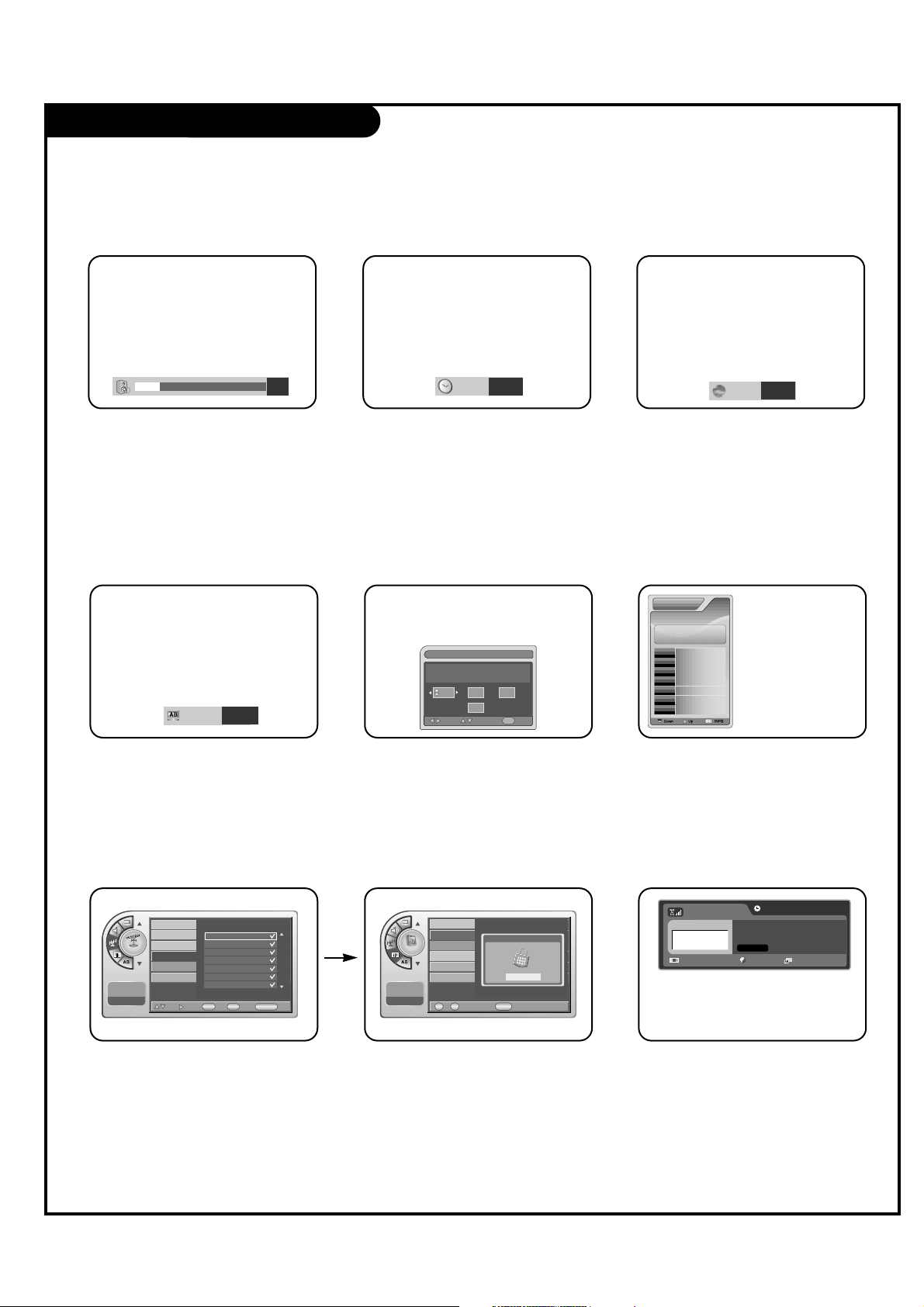
Other Menus & On-Screen Displays
PAGE 18
Use the remote keys indicated below to access these menus and displays.
In this manual, the OSD (On Screen Displays shown) may be different than those on the actual TV.
The following are generic examples to familiarize you with the TVs options.
19 Off
1
2
6
9
3
TIMER
Volume Display
Press VOLUME. Shows currently selected
sound setting.
Sleep Timer Menu
Press TIMER. Sets a time to automatically
turn the TV off and shows remaining time
before TV shutoff.
Service1
CAPTION
SAP Display
Selects MTS sound: Mono, Stereo, and
SAP in analog mode. Change the audio
language in DTV mode.
Caption Display
Press CC. Turns selected option on or off.
See Closed Captions page to select
options.
Alarm Timer
Current Time 11:17 AM
Exit
AdjustMove
OK
Hr.
Off
Min.
Alarm Display
Press ALARM. Set a time for the TV to
turn itself on.
Channel
Channel List (1/1)
ANALOG 14
ANALOG 15
ANALOG 16
DIGITAL 7-1
DIGITAL 11-1
DIGITAL 84-1
DIGITAL 88-1
Add
Move Add/Del
View
OK
V-Chi p
CC
CH PREVIEW
EXIT
Antenna
Auto Program
Channel Label
Channel List
Fine Tune
Signal Strength
-- : -- --
--. -- ----
Channel Preview
Press CH PREVIEW. Displays available TV
channels.
Setup
Enter your PIN.
----
0 9
CC
EXITNumber~
Time
V-Chip
PC
Menu Language
Menu Transparency
Set ID
-- : -- --
--. -- ----
V-Chip
Press CC. Move to the V-Chip menu.
CURRENT GUIDECURRENT GUIDE
No Information
84-1
6/23 Fri
PM 2:25
No Information
Guide Display
Press GUIDE to view DTV program
information.
DIGITAL 84-1
No Time Information
No Title
N/A
1920*1080@60Hz Korean N/A
Dolby Digital
INFO
Press INFO. Check the current program
information.
English
SAP
 Loading...