

LG L23W36 Service Manual
SERVICE MANUAL
Product Type: LCD TV
Chassis: ML-027C
Manual Part #: 3828VD0140J
Model Line:
Product Year: 2003
L23W36
Model Series:
CONTENTS
Specifications ..............................................................4
Description of Controls .................................................5
Adjustment Instructions ................................................7
Diagrams ...................................................................11
Parts List ...................................................................17
Schematics ....................................................................
Published June 2003
by Technical Publications
Zenith Electronics Corporation
201 James Record Road
Huntsville, Alabama 35824-1513
Copyright © 2003 by Zenith Electronics Corporation
Printed in Korea

- 2 -
PRODUCT SAFETY
IMPORTANT SAFETY NOTICE
This manual was prepared for use only by properly trained audiovisual service
technicians. When servicing this product, under no circumstances should the
original design be modified or altered without permission from Zenith
Electronics Corporation. All components should be replaced only with types
identical to those in the original circuit and their physical location, wiring, and
lead dress must conform to original layout upon completion of repairs. If any
fuse (or Fusible Resistor) in this TV receiver is blown, replace it only with the
factory specified fuse type and rating. When replacing a high wattage resistor
(Oxide Metal Film Resistor, over 1W), keep the resistor 10mm away from PCB.
Always keep wires away from high voltage or high temperature parts.
Special components are also used to prevent shock and fire hazard.
These components are indicated by the letter “x” included in their component
designators and are required to maintain safe performance. No deviations are
allowed without prior approval by Zenith Electronics Corporation. Service work
should be performed only after you are thoroughly familiar with these safety
checks and servicing guidelines.
Circuit diagrams may occasionally differ from the actual circuit used.
This way, implementation of the latest safety and performance improvement
changes into the set is not delayed until the new service literature is printed.
CAUTION: Do not attempt to modify this product in any way.
Never perform customized installations without manufacturer’s
approval.
Unauthorized modifications will not only void the warranty, but may
lead to property damage or user injury.
GENERAL GUIDANCE
An lsolation Transformer should always be used during the servicing
of a receiver whose chassis is not isolated from the AC power line. Use a
transformer of adequate power rating to protect against personal injury from
electrical shocks. It will also protect the receiver and its components from being
damaged by accidental shorts of the circuitry that may be inadvertently
introduced during the service operation.
Before returning the receiver to the customer, always perform an AC leakage
current check on the exposed metallic parts of the cabinet, such as antennas,
terminals, etc., to be sure the set is safe to operate
without damage of electrical shock.
LEAKAGE CURRENT COLD CHECK
(ANTENNA COLD CHECK)
With the instrument’s AC plug removed from AC source, connect an electrical
jumper across the two AC plug prongs. Place the AC switch in the on position,
connect one lead of ohm-meter to the AC plug prongs tied together, and touch
other ohm-meter lead in turn to each exposed metallic parts such as antenna
terminals, phone jacks, etc. If the exposed metallic part has a return path to the
chassis, the measured resistance should be between 1MΩ and 5.2MΩ. When
the exposed metal has no return path to the chassis the reading must be
infinite. Any other abnormality that exists must be corrected before
the receiver is returned to the customer.
ELECTROSTATICALLY SENSITIVE DEVICES
Some semiconductor (solid-state) devices can be damaged easily by static
electricity. Such components commonly are called Electrostatically Sensitive
(ES) Devices. Examples of typical ES devices are integrated circuits and some
field-effect transistors and semiconductor “chip” components. The following
techniques should be used to help reduce the incidence of component damage
caused by static electricity.
1. Immediately before handling any semiconductor component or
semiconductor-equipped assembly, drain off any electrostatic charge on the
body by touching a known earth ground. Alternatively, obtain and wear a
commercially available discharging wrist strap device, which should be
removed for potential shock reasons prior to applying power to the unit under
test.
2. After removing an electrical assembly equipped with ES devices, place the
assembly on a conductive surface such as an ESD mat, to prevent
electrostatic charge buildup or exposure of the assembly.
3. Use only a grounded-tip soldering iron to solder or unsolder ES devices.
4. Use only an anti-static solder removal device. Some solder removal devices
not classified as “anti-static” can generate electrical charges sufficient to
damage ES devices.
5. Do not use freon-propelled chemicals. These can generate electrical charge
sufficient to damage ES devices.
6. Do not remove a replacement ES device from its protective package until
immediately before you are ready to install it. (Most replacement ES devices
are packaged with leads electrically shorted together by conductive foam,
aluminum foil, or comparable conductive material.)
7. Immediately before removing the protective material from the leads of a
replacement ES device, touch the protective material to the chassis or circuit
assembly into which the device will be installed.
Caution: Be sure no power is applied to the chassis or circuit, and observe
all other safety precautions.
8. Minimize bodily motions when handling unpackaged replacement ES
devices. (Otherwise, seemingly harmless motion, such as the brushing
together of your clothing or the lifting of your foot from a carpeted floor, can
generate static electricity sufficient to damage an ES device.)
REGULATORY INFORMATION
This equipment has been tested and found to comply with the limits for a Class
B digital device, pursuant to Part 15 of the FCC Rules.
These limits are designed to provide reasonable protection against harmful
interference when the equipment is operated in a residential installation. This
equipment generates, uses and can radiate radio frequency energy and, if not
installed and used in accordance with the instruction manual, may cause
harmful interference to radio communications. However, there is no guarantee
that interference will not occur in a particular installation. If this equipment does
cause harmful interference to radio or television reception, which can be
determined by turning the equipment off and on, the user is encouraged to try
to correct the interference by one or more of the following measures: Reorient
or relocate the receiving antenna; Increase the separation between the
equipment and receiver; Connect the equipment into an outlet on a circuit
different from that to which the receiver is connected; Consult the dealer or an
experienced radio/TV technician for help.
The responsible party for this device’s compliance is:
Zenith Electronics Corporation
201 James Record Road
Huntsville, AL 35824, USA
Digital TV Hotline: 1-877-993-6484

- 3 -
SPECIFICATIONS.................................................................4
DESCRIPTION OF CONTROLS...........................................5
ADJUSTMENT INSTRUCTIONS ..........................................7
TROUBLESHOOTING ........................................................10
PRINTED CIRCUIT BOARD ...............................................11
BLOCK DIAGRAM...............................................................15
EXPLODED VIEW...............................................................16
EXPLODED VIEW PARTS LIST.........................................17
REPLACEMENT PARTS LIST............................................18
SCHEMATIC DIAGRAM..........................................................
TABLE OF CONTENTS
- 4 -
SPECIFICATIONS
MODEL
Width (inches)
Height (inches)
Depth (inches)
Weight (pounds)
Power Requirement
Television System
Television Channel
Television Screen
Power Consumption
External Antenna Impedance
Audio Output
L23W36
23.6
20.6
8.1
22
AC100-240V ~ 60Hz
NTSC
VHF : 2 ~ 13, UHF : 14 ~ 69, Cable : 01 ~ 125
LCD Panel
See the back of the set
75 Ω
7 W + 7 W
- 5 -
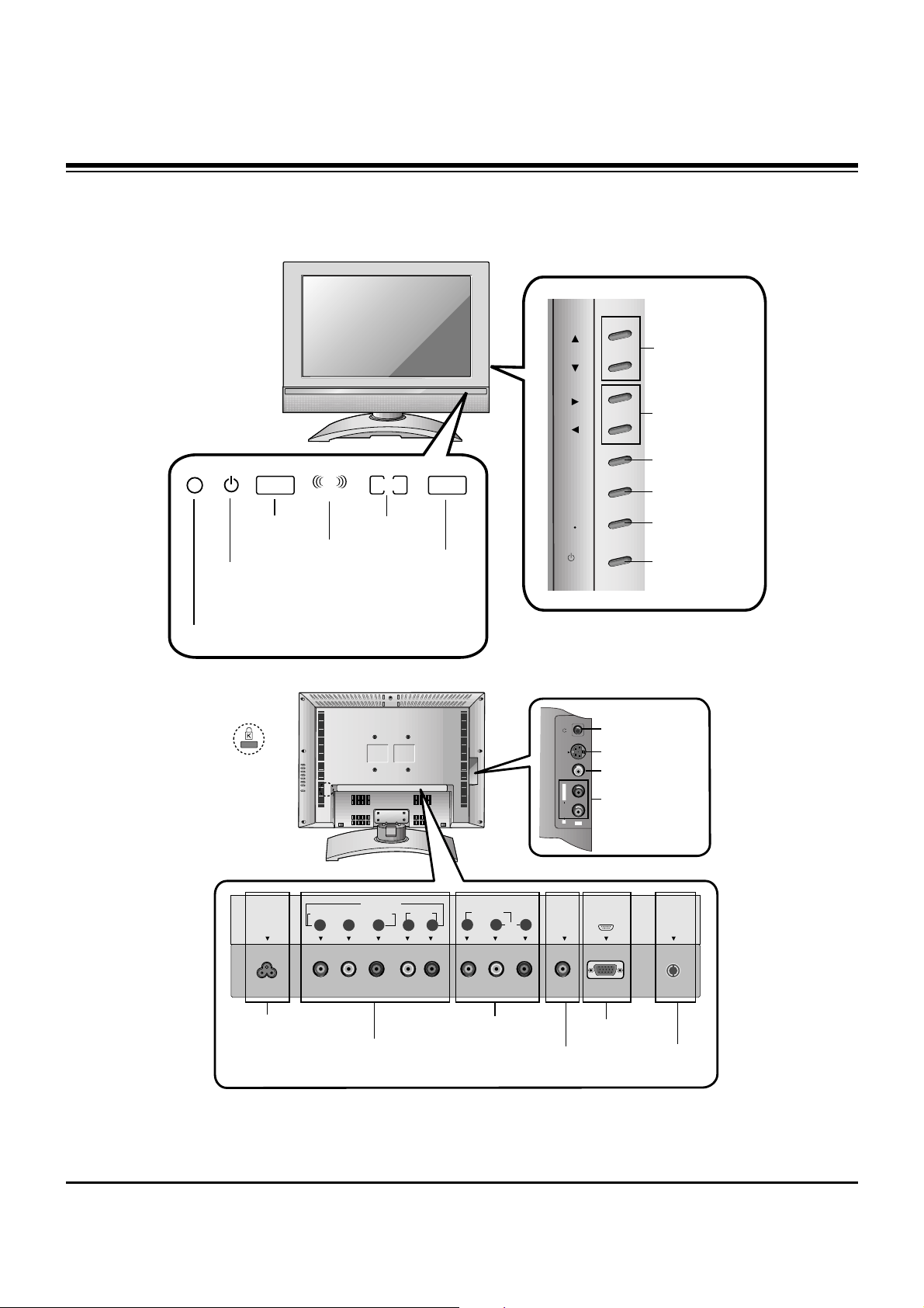
DESCRIPTION OF CONTROLS
Controls & Connection Options
Controls & Connection Options
ANT IN
+75 Ω
COMPONENT(480i/480p/720p/1080i)
PC
SOUND
VIDEO IN
DVD/DTV IN
AUDIO
VIDEO
P
R
P
B
Y
AUDIO(MONO)
LR
L
R
PC INPUT
AC INPUT
S-VIDEO VIDEO
AUDIO
R
IN2
L / MONO
MONO DPM
SAP
STEREO
ST
Remote Control Sensor
DPM Indicator
SAP Indicator
Mono Indicator
Power/Standby Indicator
Glows red in Standby mode,
Glows green when the TV is turned on.
Stereo Indicator
Headphone Jack
S-Video Input
Video Input
Audio Input
AC Input
DVD/DTV Input
(Component (480i/480p/720p/1080p), Audio)
Audio / Video Input
PC Sound Input
PC Input
Antenna Input
Channel Buttons
Volume Buttons
ch
vol
menu
enter
on/off
tv
video
/ I
Enter Button
Menu Button
TV·Video Button
On/Off Button
* Kensington Security
System Connector
- 6 -
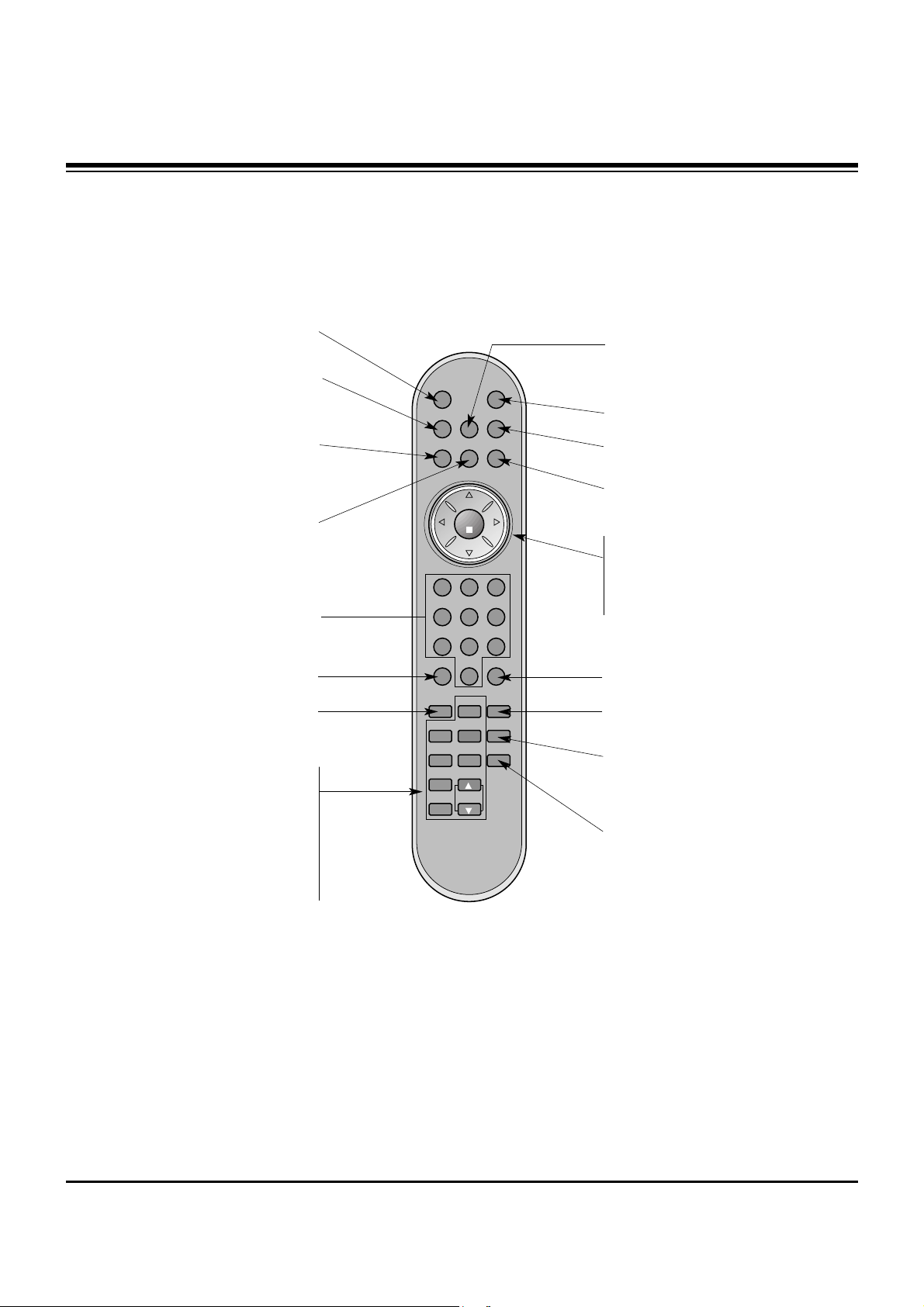
- When using the remote control, aim it at the remote control sensor on the TV.
powermute
tv/video
multimedia
mts
fcr
ch
ch
vol
enter
1 2 3
4 5 6
7 8 9
0
vol
exit
menu
audio
piparc cc
video
pip input flashbkposition
pip swap sleepsize
still
scan
ch
MUTE
Switches the sound on or off.
PIP
POSITION
PIP INPUT
SIZE
PIP SWAP
STILL
SCAN
CH (
DD/ EE
)
ENTER
CH
DD / EE
(Channel button)
VOL
FF / GG
(Volume button)
POWER
MTS
EXIT
MENU
MULTIMEDIA
Selects:
TV, Component, or RGB-
PC
mode.
VIDEO
CC
FLASHBK
Press the FLASHBK button to
return to the last channel you were
watching.
SLEEP
AUDIO
ARC
TV/VIDEO
Selects: TV, Video 1, Video 2, S-
Video
, Component, or RGB-PC
mode.
FCR
NUMBER buttons
Remote Control Key Functions
Remote Control Key Functions
DESCRIPTION OF CONTROLS

- 7 -
1. Application Object
This instruction is for the application to the LCD TV.
2. Notes
(1) This set uses an adapter, so connect the adapter and the
set correctly before adjustment.
(2) Adjustments must be performed in the correct sequence.
(3) Adjustments must be performed in an enviorment of
25
!5cC (68-85 degrees F) of temperature and 65!10% of
relative humidity.
(4) The input voltage of the receiver must keep 100~240V,
50/60Hz in adjusting.
(5) The set must be operated for 15 minutes prior to adjustment.
[ ‘Heat Run’ must be performed with the full white signal or TV
noise signal.
3. PC Input Mode Adjustment
3-1. Required Test Equipment
(1) A pattern generator; Gray pattern of 16 tones with angle
outline in the quadrilateral (MSPG-925LTH)
(2) An adjustment Remote.
3-2. Preparation for Adjustment
(1) Perform ‘Heat Run’ for more than 15 minutes in white
pattern.
(2) Connect the signal of pattern generator with LCD TV.
3-3. Auto Gray Adjustment
(1) Apply the gray signal XGA(1024X768) 16 tones from a
signal generatror.
(2) In Service menu mode, adjust the Auto gray from 0 to 1 by
using Vol(+) button.
ADJUSTMENT INSTRUCTIONS

- 8 -
ADJUSTMENT INSTRUCTIONS
4. Position Adjustment
Mode
H_Display
V_Display
V_Frequency
H_Total
H_Blanking
H_Sync
H_Polarity
H_Vp
H_Fp
H-Freq[KHz]
/Clk[MHz]
V_Total
V_Blanking
V_Sync
V_Polarity
V_Bp
V_Fp
VGA-60
640
480
60
800
160
96
NEG.
48
16
31.469
25.175
525
45
2
NEG
33
10
VGA-67
640
480
67
864
224
64
NEG.
96
64
35.0
30.24
525
45
3
NEG
39
3
VGA-75
640
480
75
840
200
64
NEG
120
16
37.5
31.5
500
20
3
NEG
16
1
VGA-85
640
480
82
832
192
56
NEG
80
56
43.269
36.0
509
29
3
NEG
25
1
SVGA-56
800
600
56
1024
224
72
POS
128
24
35.156
36.0
62.5
25
2
POS
22
1
SVGA-60
800
600
60
1056
256
128
POS
88
40
37.879
40.0
628
28
4
POS
23
1
SVGA-72
800
600
72
1040
240
120
POS
64
56
48.077
50.0
666
66
6
POS
23
37
Mode
H_Display
V_Display
V_Frequency
H_Total
H_Blanking
H_Sync
H_Polarity
H_Vp
H_Fp
H-Freq[KHz]
/Clk[MHz]
V_Total
V_Blanking
V_Sync
V_Polarity
V_Bp
V_Fp
SVGA-75
800
600
75
1056
256
80
POS
160
16
46.875
49.5
625
25
3
POS
21
1
SVGA-
85800
600
85
1048
248
64
POS
152
32
53.674
56.25
631
31
3
POS
27
1
XGA-60
1024
768
60
1344
320
136
NEG
136
160
48.363
65.0
806
38
6
NEG
29
3
XGA-70
1024
768
70
1328
304
136
NEG
144
24
56.476
75.0
806
38
6
NEG
29
3
XGA-75
1024
768
75
1312
288
96
POS
176
16
60.023
78.75
800
32
3
POS
28
1
XGA-85
1024
768
82
1376
352
96
POS
208
48
68.677
84.997
808
40
3
POS
36
1
WXGA-50
1280
768
50
1648
368
128
NEG
184
56
39.518
65.125
791
23
7
POS
15
1
WXGA-60
1280
768
60
1680
400
136
NEG
200
64
47.693
80.125
795
27
7
POS
19
1
 Loading...