

LG L1910PL Service Manual
COLOR MONIT OR
SER VICE MANUAL
Website:http://biz.LGservice.com
E-mail:http://www.LGEservice.com/techsup.html
CAUTION
BEFORE SERVICING THE UNIT,
READ THE SAFETY PRECAUTIONS IN THIS MANUAL.
CHASSIS NO. : CL-42
MODEL: L1910P (L1910PL-AF**R)
( ) **Same model for Service
*To apply the Mstar Chip.
1. LCD CHARACTERISTICS
Type : TFT Color LCD Module
Size : 19inch(48cm )diagonal
Pixel Pitch : 0.294(H) x 0.294(V)
Color Depth : 8-bit, 16,777,216 colors
Electrical Interface : LVDS
Surface Treatment : Anti-Glare, Hard Coating(3H)
Operating Mode : Normally Black
Backlight Unit : 4-CCFL (Cold Cathode
Fluorescent Lamp)
2. OPTICAL CHARACTERISTICS
2-1. Viewing Angle by Contrast Ratio
≥
10
Left : -80° min., -85°(Typ)
Right : +80° min., +85°(Typ)
Top : +80° min., +85°(Typ)
Bottom : -80° min., -85°(Typ)
2-2. Luminance : 240(min), 300(Typ)
2-3. Contrast Ratio : 400(min), 700(Typ)
3. SIGNAL (Refer to the Timing Chart)
3-1. Sync Signal
• Type : Separate, Composite,
SOG (Sync On Green)
Digital
3-2. Video Input Signal
1) Type : R, G, B Analog
2) Voltage Level : 0~0.7 V
a) Color 0, 0 : 0 Vp-p
b) Color 7, 0 : 0.35 Vp-p
c) Color 15, 0 : 0.7 Vp-p
3) Input Impedance : 75 Ω
3-3. Operating Frequency
Horizontal(Analog) : 30 ~ 83kHz
Horizontal(Digital) : 30 ~ 71kHz
Vertical : 56 ~ 75Hz
4. MAX. RESOLUTION
D-sub Analog : 1280 x 1024@75Hz
DVI Digital/Analog : 1280 x 1024@60Hz
5. POWER SUPPLY
5-1. Power Adaptor(Built-in Power)
Input : AC 100-240V~, 50/60Hz , 1.0A
5-2. Power Consumption
6. ENVIRONMENT
6-1. Operating Temperature: 10°C~35°C (50°F~95°F)
(Ambient)
6-2. Relative Humidity : 10%~80%
(Non-condensing)
6-3. MTBF : 50,000 Hours
Lamp Life : 30,000 Hours(Typ)
7. DIMENSIONS (with TILT/SWIVEL)
Width : 413 mm (16.25'')
Depth : 223 mm (8.78'')
Height : 435mm (17.13'')
8. WEIGHT (with TILT/SWIVEL)
Net. Weight : 7.20kg (15.87 lbs)
Gross Weight : 9.83kg (21.67 lbs)
9. USB
Upstream : 1 port, Downstream : 2 port
Speed : Full-12Mbps, Low-1.5Mbps
CONTENTS
SPECIFICATIONS
- 2 -
SPECIFICATIONS ................................................... 2
PRECAUTIONS ....................................................... 4
TIMING CHART ....................................................... 5
OPERATING INSTRUCTIONS ................................ 6
WIRING DIAGRAM ................................................. 9
BLOCK DIAGRAM ..................................................10
DESCRIPTION OF BLOCK DIAGRAM...................11
ADJUSTMENT ...................................................... 13
TROUBLESHOOTING GUIDE .............................. 14
PRINTED CIRCUIT BOARD................................... 18
EXPLODED VIEW...................................................21
REPLACEMENT PARTS LIST ...............................23
PIN CONFIGURATION............................................27
SCHEMATIC DIAGRAM......................................... 28
MODE
POWER ON (NORMAL)
STAND-BY
SUSPEND
DPM OFF
H/V SYNC
ON/ON
OFF/ON
ON/OFF
OFF/OFF
POWER CONSUMPTION
less than 43 W
less than 3 W
less than 3 W
less than 3 W
LED COLOR
GREEN
AMBER
AMBER
AMBER
VIDEO
ACTIVE
OFF
OFF
OFF
- 3 -
Signal Connector Pin Assignment
Pin Signal (DVI-I)
1
2
3
4
5
6
7
8
9
10
11
12
13
14
15
T. M. D. S. Data2T. M. D. S. Data2+
T. M. D. S. Data2/4 Shield
T. M. D. S. Data4T. M. D. S. Data4+
DDC Clock
DDC Data
Analog Vertical Sync.
T. M. D. S. Data1T. M. D. S. Data1+
T. M. D. S. Data1/3 Shield
T. M. D. S. Data3T. M. D. S. Data3+
+5V Power
Ground
(return for +5V,
H. Sync. and V. Sync.)
Pin Signal (DVI-I)
1
8
9
17
24
16
C1
C4
C3
C2
C5
16
17
18
19
20
21
22
23
24
C1
C2
C3
C4
C5
Hot Plug Detect
T. M. D. S. Data0T. M. D. S. Data0+
T. M. D. S. Data0/5 Shield
T. M. D. S. Data5T. M. D. S. Data5+
T. M. D. S. Clock Shield
T. M. D. S. Clock+
T. M. D. S. ClockAnalog Red
Analog Green
Analog Blue
Analog H. Sync.
Analog Ground
T. M. D. S. (Transition Minimized Differential Signaling)
• DVI-I Connector (Digital/Analog)
- 4 -
WARNING FOR THE SAFETY-RELATED COMPONENT.
• There are some special components used in LCD
monitor that are important for safety. These parts are
marked on the schematic diagram and the
replacement parts list. It is essential that these critical
parts should be replaced with the manufacturer’s
specified parts to prevent electric shock, fire or other
hazard.
• Do not modify original design without obtaining written
permission from manufacturer or you will void the
original parts and labor guarantee.
TAKE CARE DURING HANDLING THE LCD MODULE
WITH BACKLIGHT UNIT.
• Must mount the module using mounting holes arranged
in four corners.
• Do not press on the panel, edge of the frame strongly
or electric shock as this will result in damage to the
screen.
• Do not scratch or press on the panel with any sharp
objects, such as pencil or pen as this may result in
damage to the panel.
• Protect the module from the ESD as it may damage the
electronic circuit (C-MOS).
• Make certain that treatment person’s body are
grounded through wrist band.
• Do not leave the module in high temperature and in
areas of high humidity for a long time.
• The module not be exposed to the direct sunlight.
• Avoid contact with water as it may a short circuit within
the module.
• If the surface of panel become dirty, please wipe it off
with a softmaterial. (Cleaning with a dirty or rough cloth
may damage the panel.)
WARNING
BE CAREFUL ELECTRIC SHOCK !
• If you want to replace with the new backlight (CCFL) or
inverter circuit, must disconnect the AC adapter
because high voltage appears at inverter circuit about
650Vrms.
• Handle with care wires or connectors of the inverter
circuit. If the wires are pressed cause short and may
burn or take fire.
PRECAUTION
CAUTION
Please use only a plastic screwdriver to protect yourself
from shock hazard during service operation.
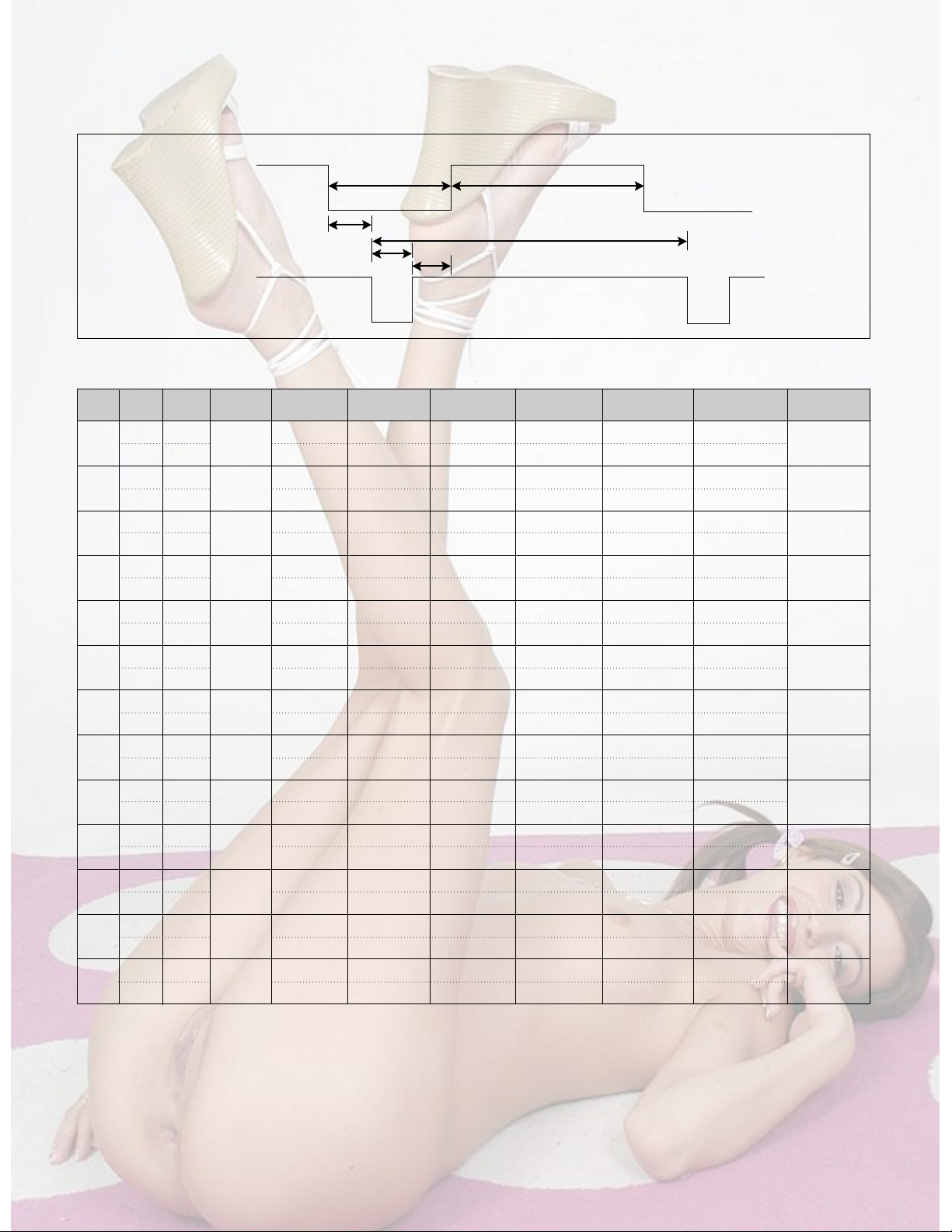
TIMING CHART
- 5 -
VIDEO
SYNC
B
D
C
F
E
A
<< Dot Clock (MHz), Horizontal Frequency (kHz), Vertical Frequency (Hz), Horizontal etc... (µs), Vertical etc... (ms) >>
H + 31.469 800 640 16 96 48
V – 70.8 449 350 37 2 60
H + 37.879 1056 800 40 128 88
V + 60.317 628 600 1 4 23
H – 31.469 800 640 16 96 48
V – 59.94 525 480 10 2 33
H – 37.5 840 640 16 64 120
V – 75 500 480 1 3 16
H – 31.468 900 720 18 108 54
V + 70.09 449 400 12 2 35
H + 46.875 1056 800 16 80 160
V + 75.0 625 600 1 3 21
H+/– 49.725 1152 832 32 64 224
V+/– 74.55 667 624 1 3 39
H – 48.363 1344 1024 24 136 160
V – 60.0 806 768 3 6 29
H – 60.123 1312 1024 16 96 176
V – 75.029 800 768 1 3 28
H+/– 68.681 1456 1152 32 128 144
V+/– 75.062 915 870 3 3 39
H+/– 61.805 1504 1152 18 134 200
V+/– 65.96 937 900 2 4 31
H + 63.981 1688 1280 48 112 248
V + 60.02 1066 1024 1 3 38
H + 79.976 1688 1280 16 144 248
V + 75.035 1066 1024 1 3 38
Mode
H/V
Sort
1
2
3
4
5
6
7
8
9
10
11
12
13
25.175
28.321
25.175
31.5
40.0
49.5
57.283
65.0
78.75
100.0
92.978
108.0
135.0
640x350
70Hz
800x600
60Hz
640x480
60Hz
640x480
75Hz
720x400
70Hz
800x600
75Hz
832x624
75Hz
1024x768
60Hz
1024x768
75Hz
1152x900
75Hz
1152x900
65Hz
1280x1024
60Hz
1280x1024
75Hz
Sync
Polarity
Frequency
Dot
Clock
Total Period
(E)
Video Active Time
(A)
Sync Duration
(D)
Back Porch
(F)
Front Porch
(C)
Resolution
- 6 -
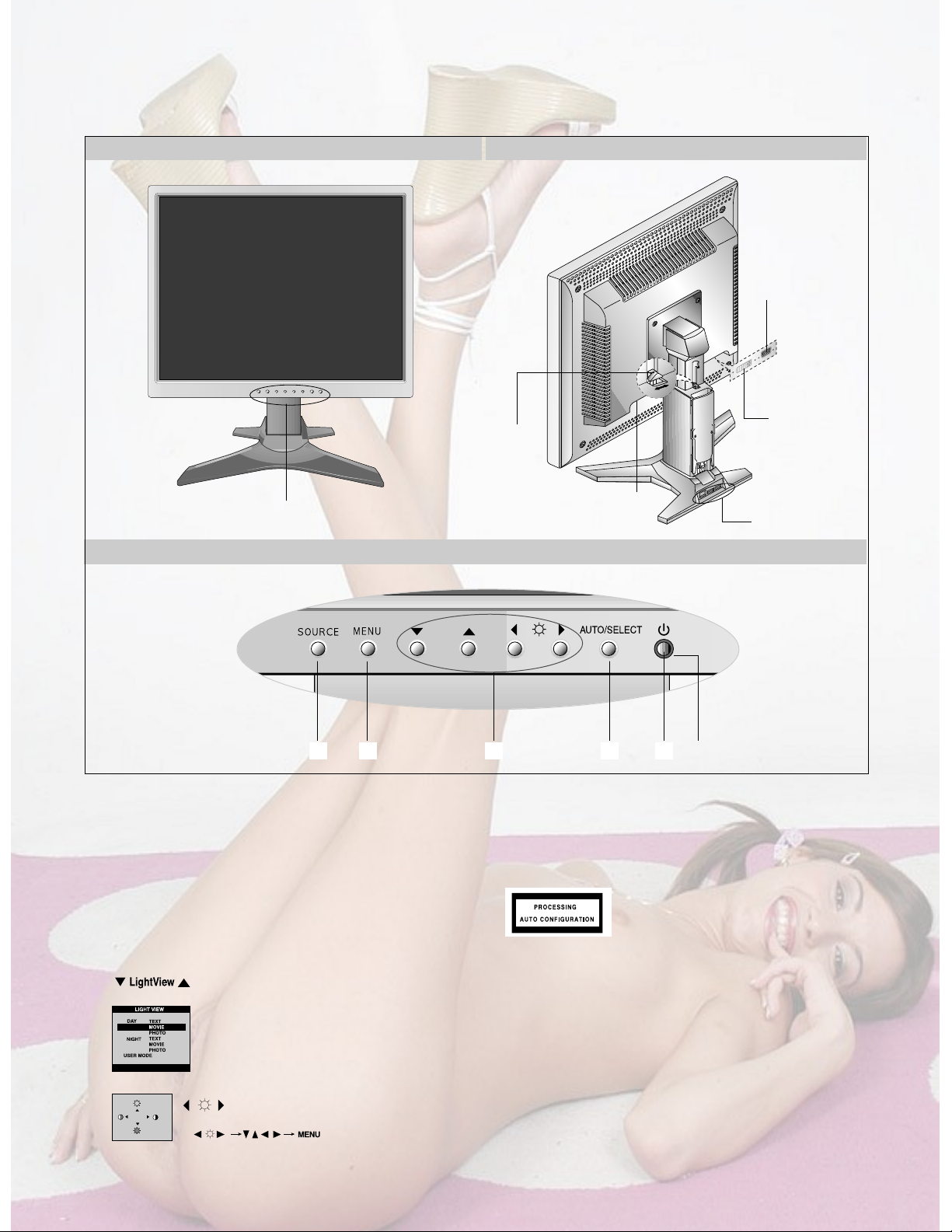
FRONT VIEW
Front Control Panel
REAR VIEW
OPERATING INSTRUCTIONS
Front Control Panel
Power Connect
Stand
Lock
USB Port
2
LightView
14 36 5
1. Power ON/OFF Button
Use this button to turn the monitor on or off.
2. Power Indicator
This indicator lights up green when the monitor
operates normally. If the display is in DPM(Energy
Saving)mode, this indicator color change to amber.
3.
▼▲◀▶
Button
Use these buttons to choose or adjust items in the On Screen
Display.
4. MENU Button
Use this button to enter or exit the On Screen Display.
5.AUTO/SELECT Button
Use this button to enter a selection in the On Screen Display.
When adjusting your display settings,
always press the AUTO/SELECT button
before entering the On Screen
Display(OSD). This will automatically adjust your display
image to the ideal settings for the current screen resolution
size(display mode). The best display mode is
1280x1024/60Hz.
6. SOURCE Button
Use this button to make Dsub or DVI connector active.
This feature is used when two computers are connected to the
monitor. The default setting is Dsub.
DVI Connect
D-Sub Signal
Connect
This function optimizes the brightness, contrast or
color value to the surrounding conditions and settings
and enables you to enjoy the most suitable picture by
adjusting the surroundings (DAY/NIGHT/USER
MODE).
•
TEXT: For viewing letters
•
MOVIE: For viewing movies
•
PHOTO: For viewing pictures or the photographs
•
USER MODE: This function memorizes the
manual adjustment -Brightness, Contrast and
Color value on the On Screen Display.
100
100
Bring up Contrast and Brightness adjustment.
:
- 7 -
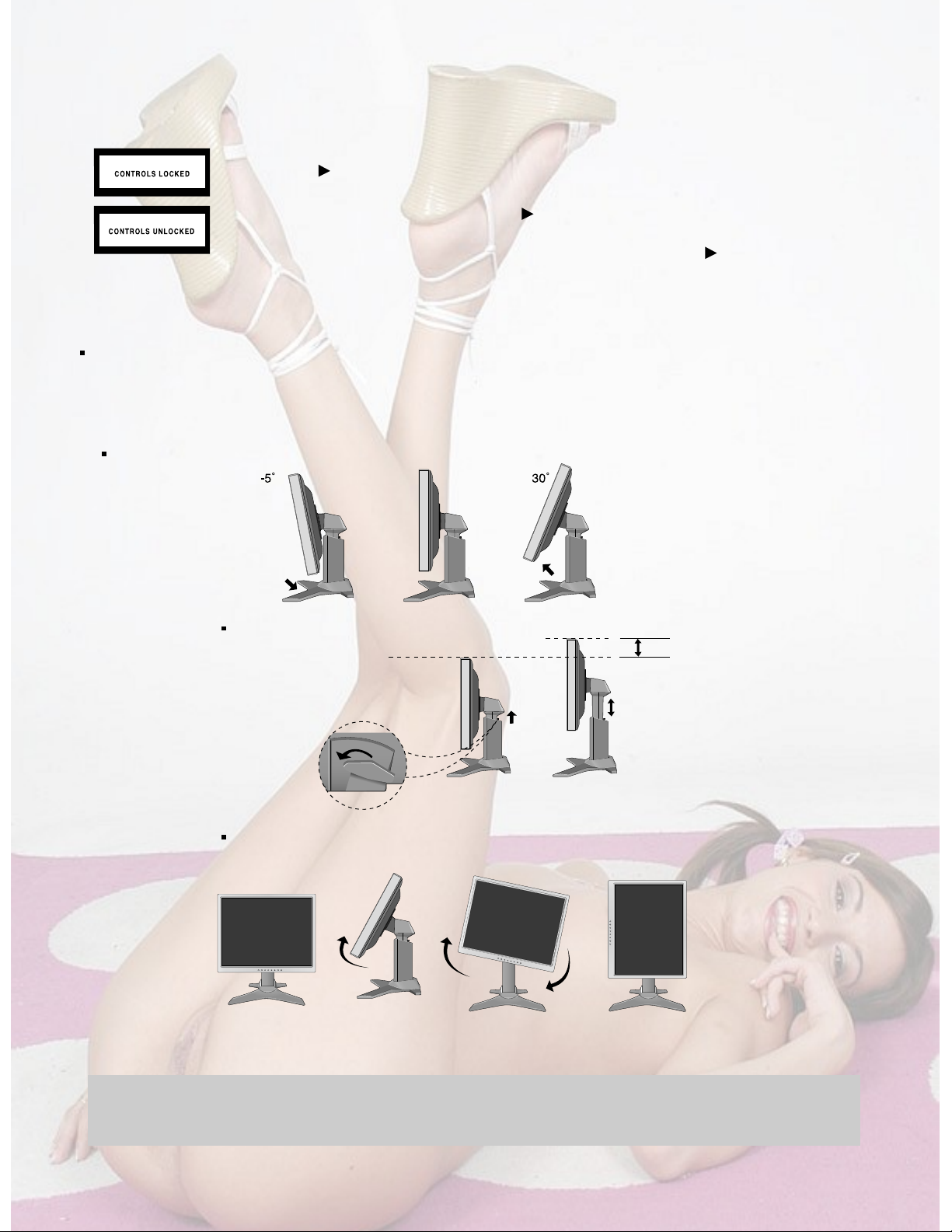
This function allows you to secure the current control settings, so that they cannot be inadvertently
changed. Press and hold the MENU button and button for 3 seconds: the message “CONTROLS
LOCKED” appears.
You can unlock the OSD controls at any time by pushing the MENU button and button for 3 seconds:
the message “CONTROLS UNLOCKED” will appear.
CONTROLS LOCKED/UNLOCKED
:
MENU and
Before setting up the monitor, ensure that the power to the monitor, the computer system, and other
attached devices is turned off.
Positioning your display
1.Adjust the position of the panel in various ways for maximum comfort.
Tilt Range : -5˚~30˚
Ergonomic
It is recommended that in order to maintain an ergonomic and comfortable viewing position, the forward tilt angle of the monitor should not
exceed 5 degrees.
Height Range : maximun 3.15 inch (80.0mm)
Landscape & Portrait : You can rotate the panel 90
o
clockwise.
(* For detailed information, please refer to the Pivot Sofeware CD provided.)
* Make sure not to touch the
floor when the head rotates
to use the Pivot function.
80.0mm
Unfasten the [Stand lock]
clockwise to adjust the
height of the stand.
- 8 -
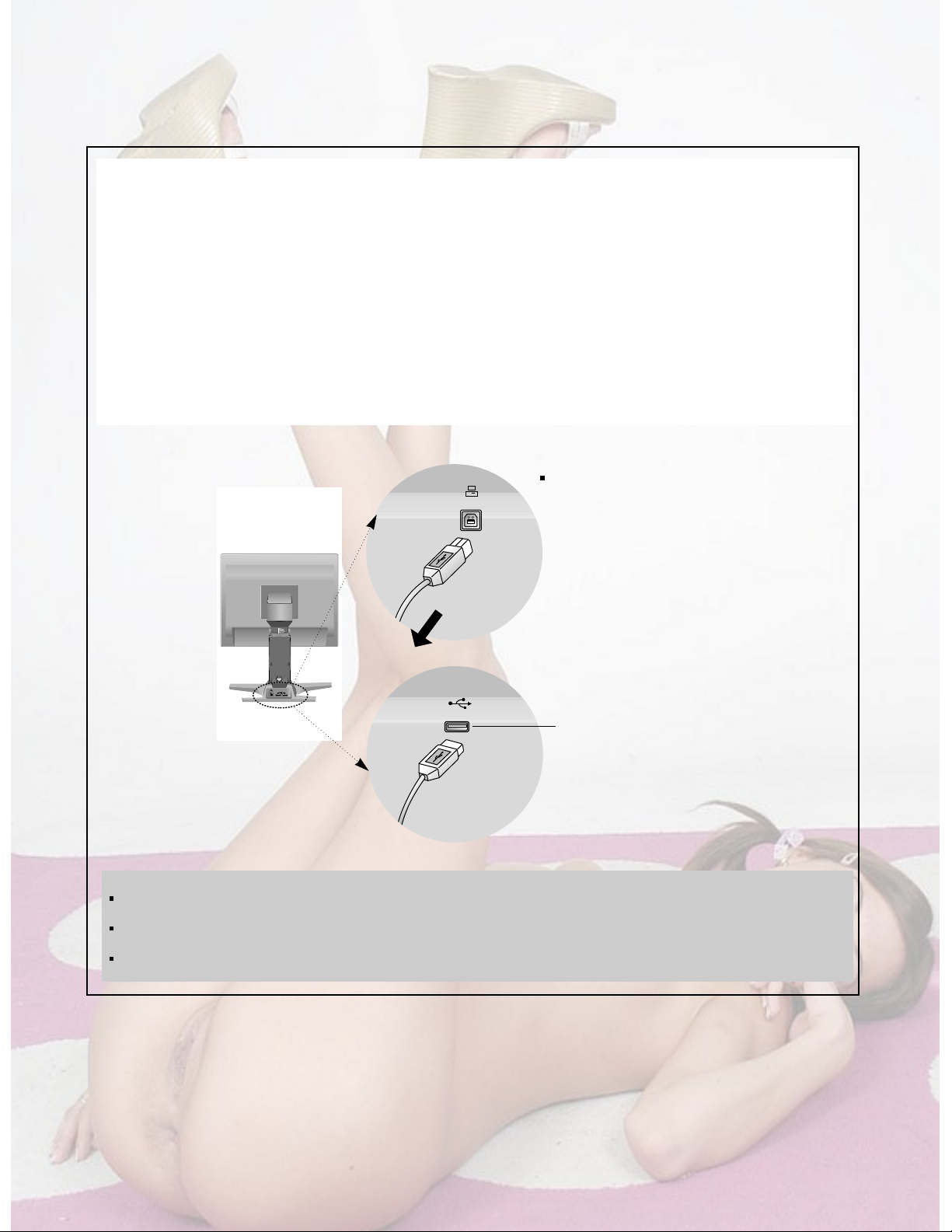
Making use of USB (Universal Serial Bus)*
USB (Universal Serial Bus) is an innovation in connecting your different desktop peripherals conveniently to your
computer. By using the USB, you will be able to connect your mouse, keyboard, and other to your monitor instead of
having to connect them to your computer. This will give you greater flexibility in setting up your system. USB allows you
to connect chain up to 120 devices on a single USB port, and you can “hot” plug (attach them while the computer is
running) or unplug them while maintaining Plug and Play auto detection and configuration. This monitor has an integrated
BUS-powered USB hub, allowing up to 2 other USB devices to be attached it.
USB connection
1. Connect the upstream port of the Display to the downstream port of the USB compliant PC or another hub using the
USB cable. (Computer must have a USB port)
2. Connect the USB compliant peripherals to the downstream ports of the monitor.
NOTE
To activate the USB hub function, the monitor must be connected to a USB compliant PC(OS) or another hub with the USB
cable(enclosed).
When connecting the USB cable, check that the shape of the connector at the cable side matches the shape at the connecting
side.
Even if the monitor is in a power saving mode, USB compliant devices will function when they are connected the USB ports(both
the upstream and downstream) of the monitor.
USB downstream Port
connect the cables from USB compliant
peripherals-such as keyboard, mouse,
etc
This is a simplified representation
of rear view.
To USB downstream port of
the USB compliant PC or
another hub cable
USB upstream Port
PUSH
J702
J706
J705
CN002
CN103CN102
CN104CN105
- 9 -
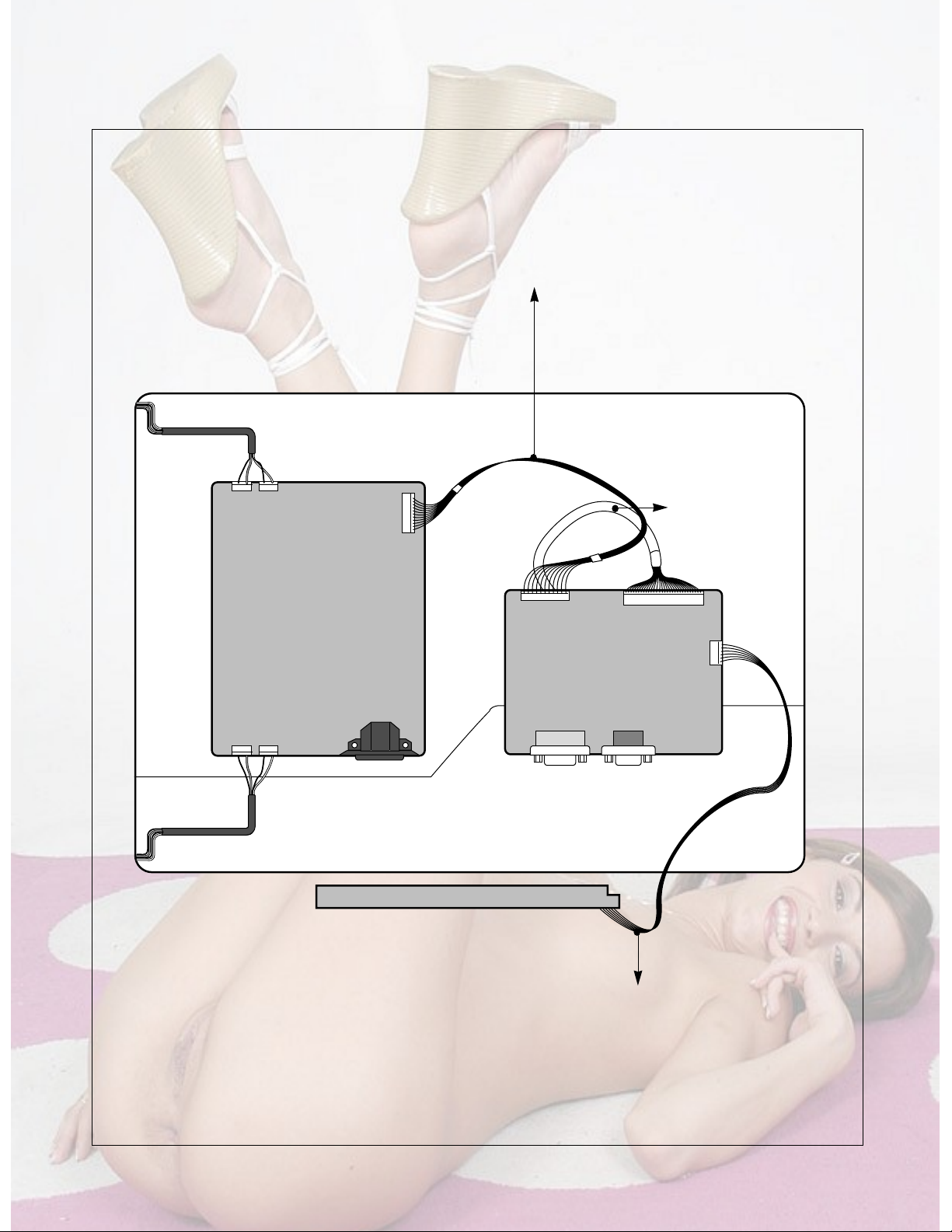
WIRING DIAGRAM
Connector Ass’y P/N:
6631T20023E
Connector Ass’y P/N:
6631T11012W
Connector Ass’y P/N:
6631T20022E
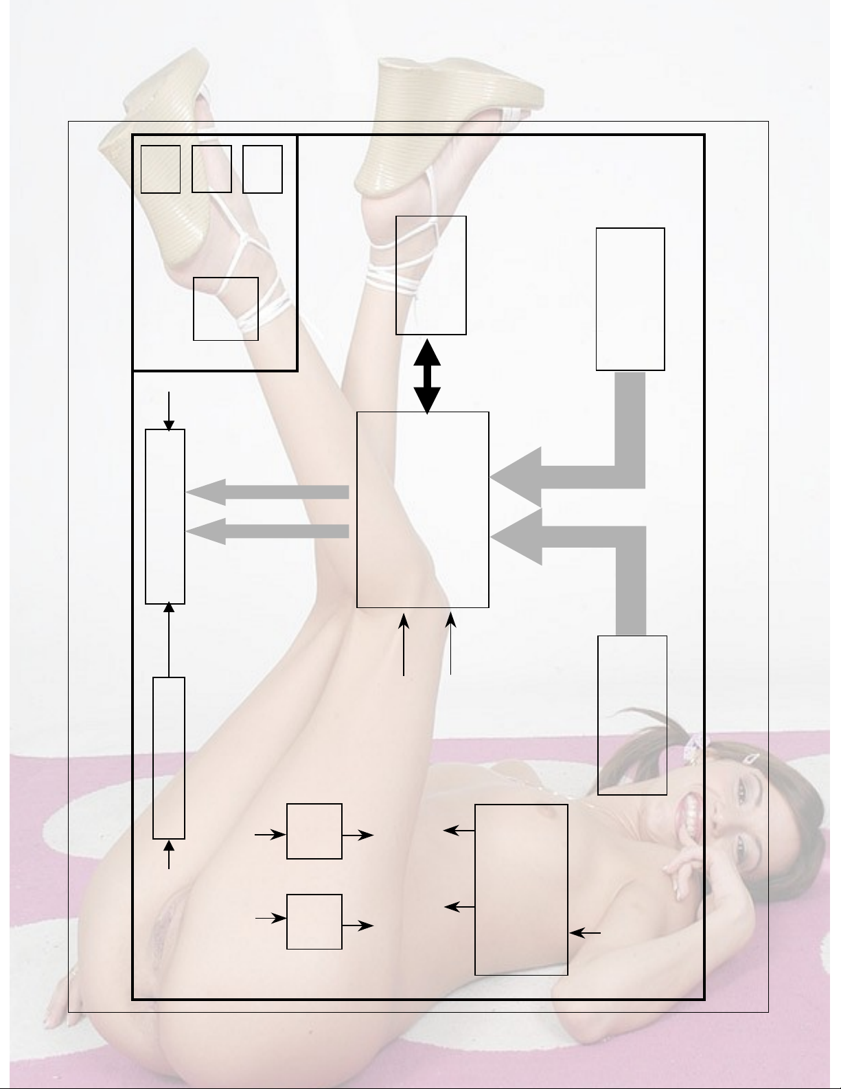
- 10 -
D-SUB
MST9151
including
(ADC/LVDS/SCALER
/INPUT SWITCHING
/TMDS )
MTV312
Micom
LCD Module
R,G,B
differential
LVDS
(Low Voltage
Differential
Signaling)
5
12V
V
DVI-I
R,G,B, H/V Sync
Digital Signal or
Analog R,G,B,H/V
3.3V
Reg.
2.5V
Reg.
5V
5V
Power
5V
AC Input
Inverter Output
Inverter
12V
U/S
D/S
USB
HUB
D/S
Bus-power USB
3.3V
2.5V
3.3V
2.5V
BLOCK DIAGRAM
- 11 -
DESCRIPTION OF BLOCK DIAGRAM
1. Video Controller Part & Display Data Transmitter Part.(MST9151)
This part amplifies the level of video signal for the digital conversion and
converts from the analog video signal to the digital video signal using a pixel clock.
The pixel clock for each mode is generated by the PLL.
The range of the pixel clock is from 25MHz to 135MHz.
This part consists of the Scaler.
The Scaler gets the video signal converted analog to digital,
interpolates input to 1280 x 1024 resolution signal and outputs 8-bit R, G, B signal to transmitter.
Especially pre-amp / ADC / Video controller/ Transmitter are merged to one chip"MST9151" by MSTAR.
This part transmit digital signal from the Scaler to the receiver of module.
2. Micom Part
This Part consists of EEPROM IC which stores control data, Reset IC and the Micom.
The Micom distinguishes polarity and frequency of the H/V Sync are supplied from signal cable.
The controlled data of each modes is stored in EEPROM.
3. Power Part
This part consists of the one 3.3V and one 2.5 regulators to convert power which is provided 5V in LIPS Board.
5V is provided for LCD Panel.
Also, 5V is converted 3.3V and 2.5V by regulator. Converted power is provided for IC in the main board.
4. Inverter
The inverter converts from DC12V to AC 700Vrms and operates back-light lamps of module.
 Loading...