

LG L1515SM, L1515S Service Manual
COLOR MONIT OR
SER VICE MANUAL
Website:http://biz.LGservice.com
E-mail:http://www.LGEservice.com/techsup.html
CAUTION
BEFORE SERVICING THE UNIT,
READ THE SAFETY PRECAUTIONS IN THIS MANUAL.
CHASSIS NO. : CL-61
MODEL: L1515S (L1515SM-AL**R, AG**R)
L1515S(S) (L1515SM-AG**S)
L1515S(K) (L1515SM-AG**B)
( ) **Same model for Service
*Same looking with new chassis
CONTENTS
SPECIFICATIONS
- 2 -
1. LCD CHARACTERISTICS
Type : TFT XGA LCD Module
Size : 352.0(H) x 263.5(V) x 14.0(T)
Pixel Pitch : 0.297mm x 0.297mm
Color Depth :
6bits(with FRC)/ 16M colors
Active Video Area : 15.0inch
(304.128 x 228.096)
Surface Treatment : Anti-Glare, Hard Coating (3H)
Backlight Unit : Top/Bottom edge side 2CCFL
Electrical Interface : LVDS interface
2. OPTICAL CHARACTERISTICS
2-1. Viewing Angle by Contrast Ratio
≥
10
(LPL Module)
Left : 55° min. 65° typ. Right: 55° min. 65° typ.
Top : 45° min. 45° typ. Bottom: 50° min. 55° typ.
(CMO Module)
Left : 50° min. 60° typ. Right: 50° min. 60° typ.
Top : 30° min. 40° typ. Bottom: 50° min. 60° typ.
2-2. Luminance
:
200(min.), 250(typ.) at Center point
2-3. Contrast Ratio :300(min.), 400(typ.)
3. SIGNAL (Refer to the Timing Chart)
3-1. Sync Signal
1) Type : Separate Sync. (Horizontal & Vertical)
2) Input Voltage Level: Low=0~0.8V, High=2.1~5.5V
3) Sync Polarity : Positive or Negative
3-2. Video Input Signal
1) Type : R, G, B Analog
2) Voltage Level : 0~0.7 V
a) Color 0, 0 : 0 Vp-p
b) Color 7, 0 : 0.35 Vp-p
c) Color 15, 0 : 0.7 Vp-p
3) Input Impedance : 75 Ω
3-3. Operating Frequency
Horizontal : 30 ~ 63kHz
Vertical : 56 ~ 75Hz
4. POWER SUPPLY
4-1. Power
100-240V~, 50/60Hz 0.6A
4-2. Power Consumption
5. ENVIRONMENT
5-1. Operating Temperature: 10°C~35°C (50°F~95°F)
5-2. Operating Humidity : 10%~80%
5-3. MTBF : 50,000 Hours (Min.)
Lamp Life : 40,000 Hours (Min.)
6. DIMENSIONS (with TILT/SWIVEL)
(FULL Up Position)
Width : 350mm (13.78'')
Depth : 133mm (5.24'')
Height : 318mm (12.52'')
(Folded Position)
Width : 350mm (13.78'')
Depth : 64mm (2.52'')
Height : 334mm (13.15'')
7. WEIGHT (with TILT/SWIVEL)
Net. Weight : 2.5kg (5.51 lbs)
Gross Weight : 5.5kg (12.13 lbs)
SPECIFICATIONS ................................................... 2
PRECAUTIONS ....................................................... 3
TIMING CHART ....................................................... 4
OPERATING INSTRUCTIONS ................................ 5
WIRING DIAGRAM ................................................. 6
BLOCK DIAGRAM ................................................... 7
DESCRIPTION OF BLOCK DIAGRAM ................... 8
ADJUSTMENT ...................................................... 10
TROUBLESHOOTING GUIDE .............................. 12
EXPLODED VIEW...................................................17
REPLACEMENT PARTS LIST ...............................18
SCHEMATIC DIAGRAM......................................... 20
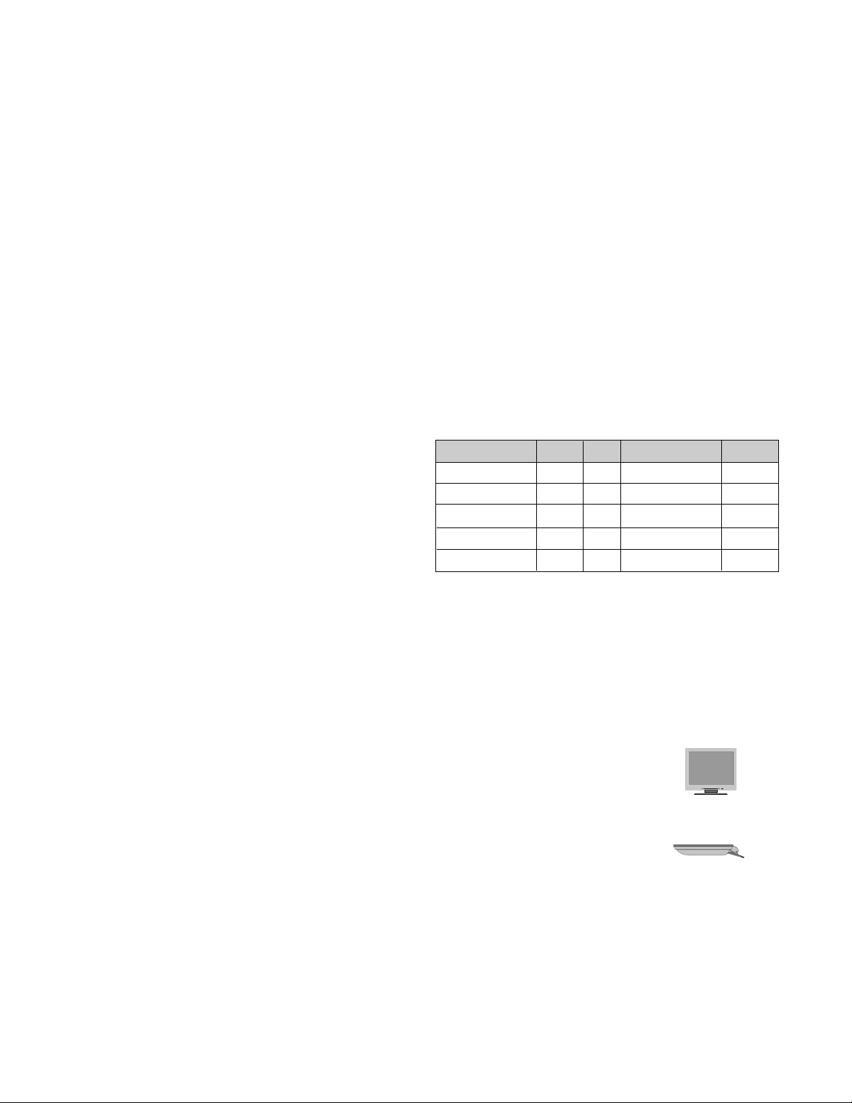
MODE
POWER ON (NORMAL)
STAND-BY
SUSPEND
DPM OFF
POWER S/W OFF
H/V SYNC
ON/ON
OFF/ON
ON/OFF
OFF
-
POWER CONSUMPTION
less than 25 W
less than 1 W
less than 1 W
less than 1 W
less than 1 W
LED COLOR
GREEN
AMBER
AMBER
AMBER
OFF
VIDEO
ACTIVE
OFF
OFF
OFF
-
- 3 -
WARNING FOR THE SAFETY-RELATED COMPONENT.
• There are some special components used in LCD
monitor that are important for safety. These parts are
marked on the schematic diagram and the
replacement parts list. It is essential that these critical
parts should be replaced with the manufacturer’s
specified parts to prevent electric shock, fire or other
hazard.
• Do not modify original design without obtaining written
permission from manufacturer or you will void the
original parts and labor guarantee.
TAKE CARE DURING HANDLING THE LCD MODULE
WITH BACKLIGHT UNIT.
• Must mount the module using mounting holes arranged
in four corners.
• Do not press on the panel, edge of the frame strongly
or electric shock as this will result in damage to the
screen.
• Do not scratch or press on the panel with any sharp
objects, such as pencil or pen as this may result in
damage to the panel.
• Protect the module from the ESD as it may damage the
electronic circuit (C-MOS).
• Make certain that treatment person’s body are
grounded through wrist band.
• Do not leave the module in high temperature and in
areas of high humidity for a long time.
• The module not be exposed to the direct sunlight.
• Avoid contact with water as it may a short circuit within
the module.
• If the surface of panel become dirty, please wipe it off
with a softmaterial. (Cleaning with a dirty or rough cloth
may damage the panel.)
WARNING
BE CAREFUL ELECTRIC SHOCK !
• If you want to replace with the new backlight (CCFL) or
inverter circuit, must disconnect the AC adapter
because high voltage appears at inverter circuit about
650Vrms.
• Handle with care wires or connectors of the inverter
circuit. If the wires are pressed cause short and may
burn or take fire.
PRECAUTION
CAUTION
Please use only a plastic screwdriver to protect yourself
from shock hazard during service operation.
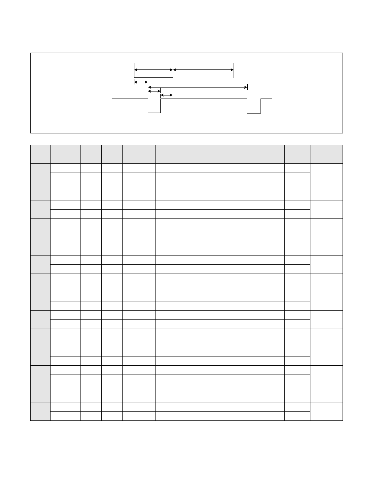
TIMING CHART
- 4 -
VIDEO
SYNC
B
D
C
F
E
A
H / V
H (Pixels)
V (Lines)
H (Pixels)
V (Lines)
H (Pixels)
V (Lines)
H (Pixels)
V (Lines)
H (Pixels)
V (Lines)
H (Pixels)
V (Lines)
H (Pixels)
V (Lines)
H (Pixels)
V (Lines)
H (Pixels)
V (Lines)
H (Pixels)
V (Lines)
H (Pixels)
V (Lines)
H (Pixels)
V (Lines)
H (Pixels)
V (Lines)
H (Pixels)
V (Lines)
Sync
Polarity
+
–
–
+
–
–
–
–
–
–
–
–
+
+
+
+
+
+
+
+
–
–
–
–
–
–
+
+
Dot
Clock
25.175
28.322
25.175
30.24
31.5
31.5
36.0
40.0
50.0
49.5
57.2832
65
75
78.75
Frequency
31.468 KHz
70.0 Hz
31.468 KHz
70.0 Hz
31.469 KHz
60.0 Hz
35.00 KHz
66.67 Hz
37.861 KHz
72.8 Hz
37.50 KHz
75.0 Hz
35.156KHz
56.25 Hz
37.879 KHz
60.3 Hz
48.077 KHz
72.188 Hz
46.875 KHz
75.0 Hz
49.725 KHz
74.55 Hz
48.363 KHz
60.0 Hz
56.476 KHz
70.0 Hz
60.023 KHz
75.0 Hz
Resolution
640 x 350
720 x 400
640 x 480
640 x 480
640 x 480
640 x 480
800 x 600
800 x 600
800 x 600
800 x 600
832 x 624
1024 x 768
1024 x 768
1024 x 768
Total
Period
( E )
800
449
900
449
800
525
864
525
832
520
840
500
1024
625
1056
628
1040
666
1056
625
1152
667
1344
806
1328
806
1312
800
Video
Active
Time ( A )
640
350
720
400
640
480
640
480
640
480
640
480
800
600
800
600
800
600
800
600
832
624
1024
768
1024
768
1024
768
Blanking
Time
( B )
160
99
180
49
160
45
224
45
192
40
200
20
224
25
256
28
240
66
256
25
320
43
320
38
304
38
288
32
Sync
Duration
( D )
96
2
108
2
96
2
64
3
40
3
64
3
72
2
128
4
120
6
80
3
64
3
136
6
136
6
96
3
Back
Porch
( F )
48
60
55
34
48
33
96
39
128
28
120
16
128
22
88
23
64
23
160
21
224
39
160
29
144
29
176
28
Front
Porch
( C )
16
37
17
13
16
10
64
3
24
9
16
1
24
1
40
1
56
37
16
1
32
1
24
3
24
3
16
1
MODE
1
2
3
4
5
6
7
8
9
10
11
12
13
14
(MAC)
(TEXT)
- 5 -
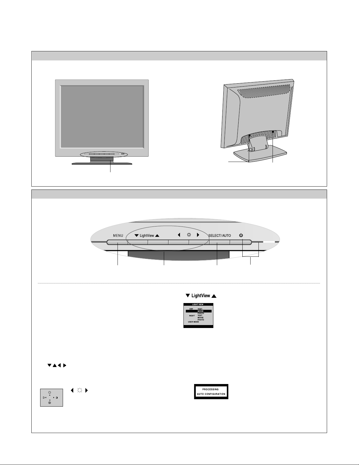
1. Power ON/OFF Button
Use this button to turn the monitor on or off.
Power Indicator
This indicator lights up green when the monitor
operates normally. If the display is in DPM(Energy
Saving)mode, this indicator color change to amber.
2. MENU Button
Use this button to enter or exit the On Screen Display.
3.
Button
Use these buttons to choose or adjust items in the On
Screen Display.
4. SELECT
/ AUTO
Button
Use this button to enter a selection in the On Screen Display.
FRONT VIEW REAR VIEW
OPERATING INSTRUCTIONS
D-Sub Signal
Connect
Front Control Panel
132 4
100
100
When adjusting your display settings,
always press the AUTO/SELECT button
before entering the On Screen
Display(OSD). This will automatically
adjust your display image to the ideal settings for the current
screen resolution size (display mode).
The best display mode is 1024x768@60Hz.
This feature lets you easily select the best desired image
condition optimized to the environment (ambient
illumination, image types etc.).
• DAY: Bright ambient illumination
• NIGHT: Dark ambient illumination
• TEXT: For text images (Word processing etc.)
• MOVIE : For animation images in videos or movies
• PHOTO : For pictures or drawings
• USER MODE : For use under user setup image
conditions (Brightness, contrast and color tint are
selected by the user in OSD Screen Setup Menu.)
See Front Control Panel
Power Connect
Bring up Contrast and Brightness adjustment.
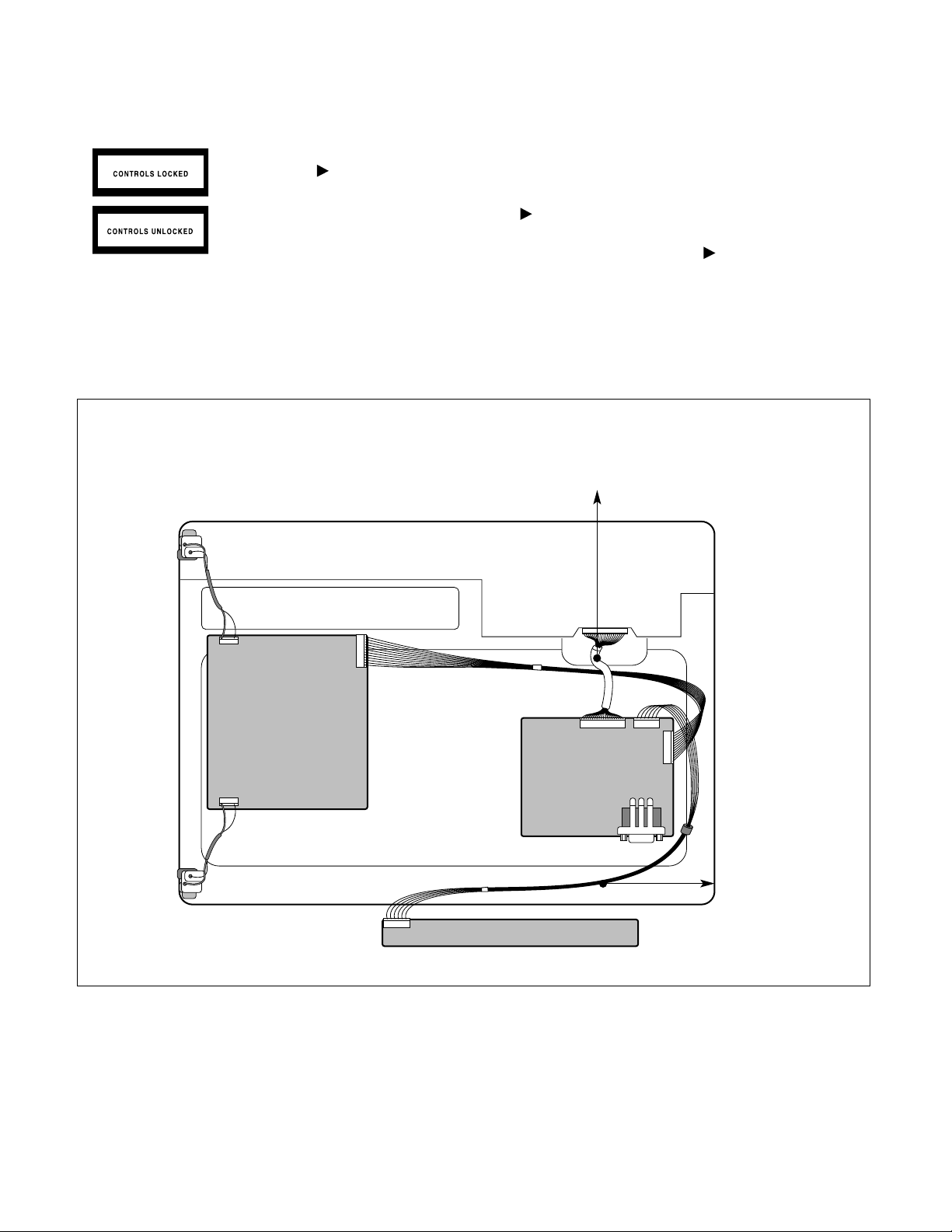
- 6 -
J706
J704
CN1
CN2
J707
J8
J1
WIRING DIAGRAM
Connector Ass’y P/N:
6631T20024B
Connector Ass’y P/N:
6631T11012R-LPL Module
6631T11021V-CMO Module
This function allows you to secure the current control settings, so that they cannot be inadvertently
changed. Press and hold the MENU button and button for 3 seconds: the message “CONTROLS
LOCKED” appears.
You can unlock the OSD controls at any time by pushing the MENU button and button for 3 seconds:
the message “CONTROLS UNLOCKED” will appear.
CONTROLS LOCKED/UNLOCKED
:
MENU and
- 7 -
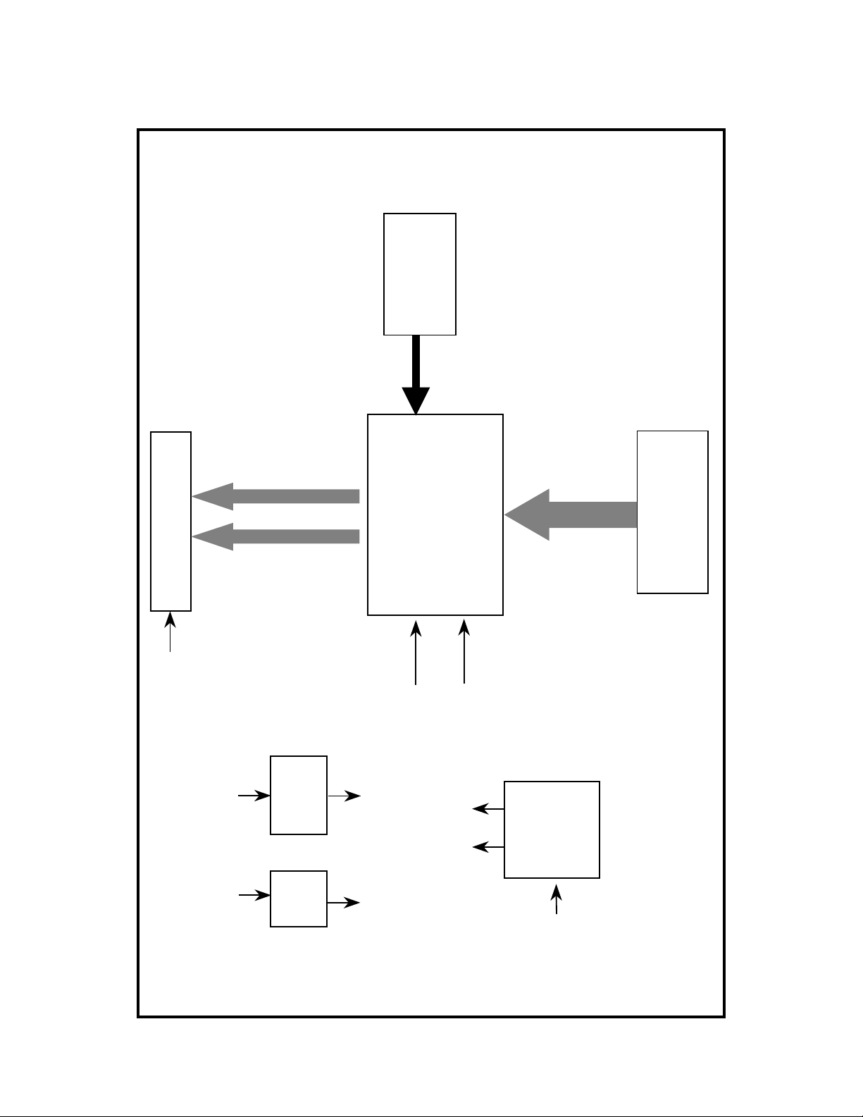
BLOCK DIAGRAM
Micom
MTV312
))
))
gg
gg
nn
nn
ii
ii
ll
ll
aa
aa
nn
nn
gg
gg
ii
ii
SS
SS
ee
ee
ll
ll
gg
gg
aa
aa
ii
aa
ii
aa
tt
tt
tt
tt
ll
ll
nn
nn
oo
oo
ee
ee
VV
VV
rr
rr
SS
SS
ee
ee
ff
ff
ww
ww
DD
DD
ff
ff
ii
ii
oo
oo
VV
VV
DD
DD
LL
LL
LL
((
LL
((
LCD Module
differential
R,G,B
5V
3.3V
5V
Diode
KDS184
3.3V
Reg.
including
MST9111B
(ADC/LVDS/SCALER )
2.5V
2.5V
3.3V
5V
R,G,B, H/V Sync
LIPS
12V
3.3V
D-SUB
AC Input

DESCRIPTION OF BLOCK DIAGRAM
- 8 -
1. Video Controller Part.
This part amplifies the level of video signal for the digital conversion and converts from the analog video signal to the
digital video signal using a pixel clock.
The pixel clock for each mode is generated by the PLL.
The range of the pixel clock is from 25MHz to 135MHz.
This part consists of the Scaler, ADC, LVDS transmitter.
The Scaler gets the video signal converted analog to digital, interpolates input to 1280 X 1024 resolution signal and
outputs 8-bit R, G, B signal to transmitter.
2. Power Part.
This part consists of the one 3.3V regulator, and two 2.5V drop diodes to convert power which is provided 12V, 5V in
Power board.
5V is provided for LCD panel and Micom.
Also, 5V is converted 3.3V by regulator and 3.3V is converted 2.5V by drop diode.
Converted power is provided for IC in the main board.
3. MICOM Part.
This part consists of EEPROM IC which stores control data, Reset IC and the Micom.
The Micom distinguishes polarity and frequency of the H/V sync are supplied from signal cable.
The controlled data of each modes is stored in EEPROM.
 Loading...