

Page 1

LG
Room
Air Conditioner
SERVICE MANUAL
LG
CAUTION
• BEFORE SERVICING THE UNIT, READ THE SAFETY
PRECAUTIONS IN THIS MANUAL.
• ONLY FOR AUTHORIZED SERVICE PERSONNEL.
MODEL: HBLG8003R,LB8000ER,LW8000ER,HBLG1003R,LWHD1006R,L1006R
LWHD1006RY6,L1006RY6
Page 2

2 Room Air Conditioner
Air Conditioner Service Manual
TABLE OF CONTENTS
Safety Precautions..........................................................................................................................................3
Dimensions .....................................................................................................................................................5
Outside Dimensions...................................................................................................................................5
Product Specifications ..................................................................................................................................6
Installation .......................................................................................................................................................7
Select the Best Location ............................................................................................................................7
Installation Check.......................................................................................................................................7
How to Secure the Drain Pipe....................................................................................................................7
How to Install..............................................................................................................................................8
Operation ......................................................................................................................................................12
Function of Controls .................................................................................................................................12
Disassembly ..................................................................................................................................................14
Mechanical Parts......................................................................................................................................14
Air handling
Parts.....................................................................................................................................15
Elect
rical Parts .........................................................................................................................................16
Ref
rigerating Cycle...................................................................................................................................18
S
chematic Diagram.......................................................................................................................................21
Wi
ring Diagram.........................................................................................................................................21
Electronic Control D
evice.........................................................................................................................22
Components Location ..............................................................................................................................23
Trou
bleshooting Guide.................................................................................................................................24
Pipeing System ................................................................................................................
........................24
Trou
bleshooting Guide .............................................................................................................................25
Exploded Vi
ew ..............................................................................................................................................37
Replacement
Parts List ................................................................................................................................38
Electrical Parts Troubleshooting Guide......................................................................................................27
Electrical Parts ........................................................................................................................................31
Page 3
Safety Precautions
Safety
Precautions
To prevent injury and property damage, follow these instructions.
Incorrect operation due to ignoring instructions might cause harm or damage, the seriousness of which is
indicated by the following symbols.
Precautions
WARNING
CAUTION
This symbol shows the possibility of death or serious injury.
This symbol indicates the possibility of injury or damage to property.
Never Do This
Always Do This
■ The following items are classified by these symbols.
WARNING
WARNING
Plug in the power plug
properly.
• Doing so may cause electric
shock or fire due to heat
generation.
Do not modify power cord
length or share the outlet
with other appliances.
• Doing so may cause electric shock or
fire due to heat generation.
Do not allow water to run
into electric parts.
• Doing so may cause failure of
machine or electric shock.
Do not use the socket if it is
loose or damaged.
Do not operate or stop the
unit by inserting or pulling
out the power plug.
• Doing so may cause electric
shock or fire due to heat
generation.
Do not operate with wet
hands or in damp
environment.
• Doing so may cause electric
shock.
Always install air leakage
breaker and a dedicated
switching board.
• Failure to install these may cause
fire or electric shock accident.
Do not open the entrance
during operation.
Do not damage or use an
unspecified power cord.
• Doing so may cause electric shock or fire.
•
If the supply cord is damaged, it must be replaced
by the manufacturer, the manufacturer's service
agent, or a similarly qualified person in order to
avoid a hazard. (Y attachment)
Always plug into a
grounded outlet.
• No grounding may cause electric
shock (See Installation Manual).
Unplug the unit if strange
sounds, odors, or smoke
comes from it.
• Such a unit may pose a risk of
fire or electric shock accident.
Keep firearms away.
• Doing so may cause fire or
electric shock.
Do not use the power cord close to heating
tools.
• Doing so may cause fire or electric shock. • Doing so may lead to an explosion or fire.
• It may cause electric shock.
Do not use the power cord near flammable gas
or combustibles such as gasoline, benzene,
thinner, etc.
Service Manual 3
Page 4
Safety Precautions
WARNING
WARNING
Ventilate before operating air conditioner
when gas goes out.
• Operating the air conditioner in the presence of gas
vapors can lead to explosions and fire.
Never touch the metal parts
of the unit when removing
the filter.
• They are sharp and may cause
injury.
When cleaning the unit, first
make sure the
cord is unplugged.
•
Since the fan rotates at high speed
during operation, it may cause
injury if activated while cleaning.
is off and the
Do not clean the air
conditioner with water.
• Water may enter the unit and
degrade the insulation. It also
may cause an electric shock.
Do not put a pet or house
plant where it will be
exposed to direct air flow.
• This could injure the pet or plant. • It may cause damage of animals
• Doing so may cause failure or electric shock.
CAUTION
CAUTION
Do not disassemble or modify products
randomly.
Operate only in a well
ventilated area when using in
the presence of a stove, etc.
• An oxygen shortage may
otherwise occur.
Do not use appliance for special
purpose such as climate control for
animals or vegetables, precision
machine, or conservation of art
or vegetables or loss of property.
articles.
Stop operation in storm or
hurricanes.
• Operation with windows opened
may cause wetting of indoor and
soaking of household furniture.
Do not place obstacles
around the absorption inlet
or output.
• Doing so may cause failure of
appliance or accident.
Do not use abrasives or strong
detergent such as wax or
thinner. Always use a soft cloth.
• Otherwise, the products appearance may
be damaged due to change of product
color or scratching of its surface.
If water enters the product, turn off the the
power switch of the main body of appliance.
Contact service center after taking the powerplug out from the socket.
Hold the plug by the head
when taking it out.
• Improper handling may cause
electric shock or damage.
Ensure that an installation console of
the outdoor appliance is not damaged
due to extened use.
• If the previous air conditioner
damaged the console, there is a
risk of the new unit falling.
Do not place heavy object on the
power cord and take care so that
the cord is not pinched.
• Treating the power cord
carelessly poses a danger of fire
or electric shock.
Turn off the main power
switch when not using it for
a long time.
• Doing so can prolong the life of
the product.
Always insert filters
securely. Clean them every
two weeks.
• Operation without filters will
cause failure.
Do not drink water drained
from air conditioner.
• It contains contaminants that
would make you sick.
Do not direct airflow at room occupants only.
4 Room Air Conditioner
• This could damage your health.
Page 5
Dimensions
Dimensions
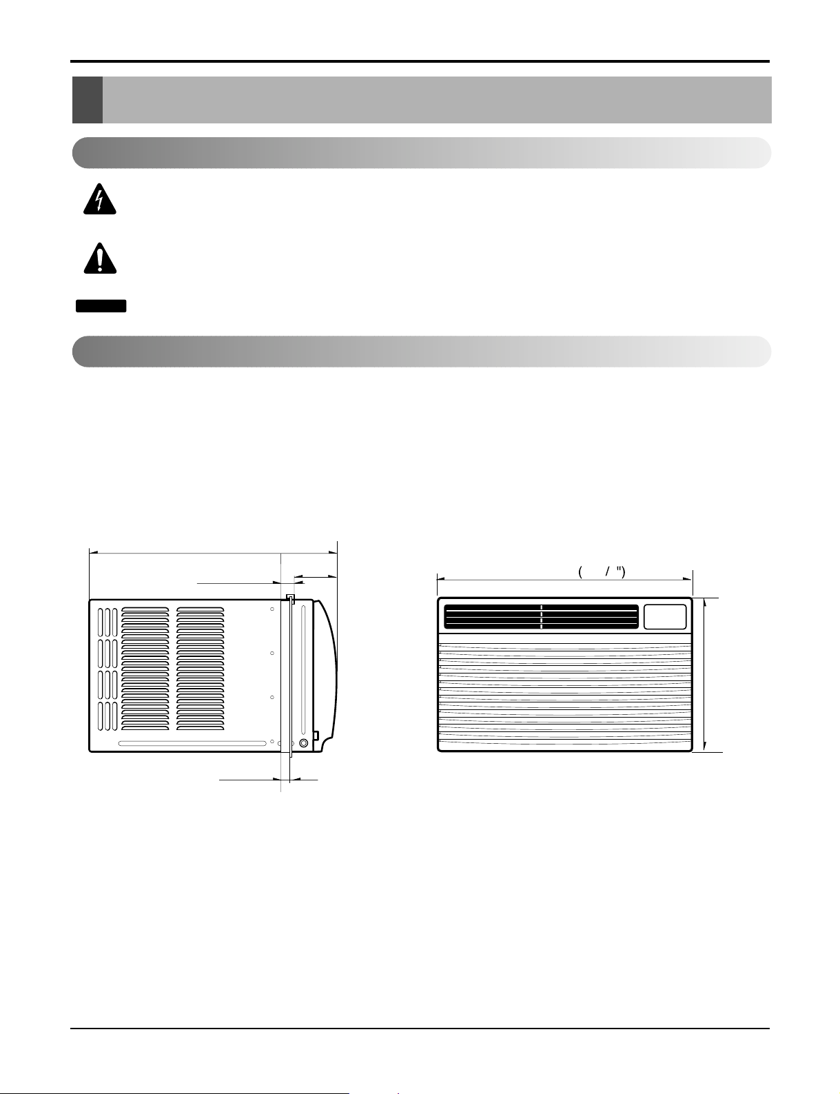
Outside Dimensions
This symbol alerts you to the risk of electric shock.
This symbol alerts you to hazards that could cause harm to the
air conditioner.
This symbol indicates special notes.
NOTICE
Symbols Used in this Manual
490(19 / )
3
8"
29(1 / )
18( / )
unit: mm(inch)
31
126.5(4 / )
5
32"
23
32"
32"
510
20
3
32
DEFROST
HEAT
COOL
FAN
DRY
FAN
ENERGY
SAVER
AIR
INDOOR DESIRED
PURYFIER
AUTO
RESTART
354(13 / ")
29
32
Service Manual 5
Page 6
6 Room Air Conditioner
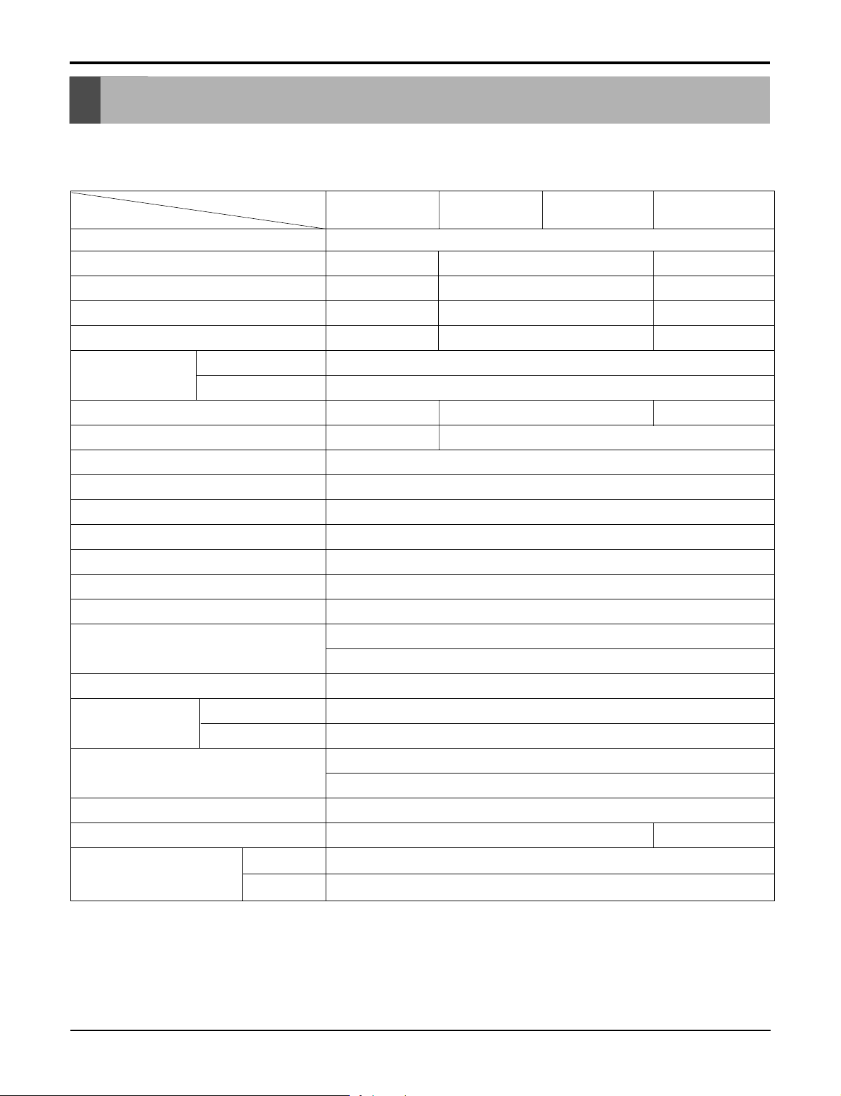
Specfications
Product SpecificationsPrProduct Specificationsoduct SpecificationsProduct Specifications
MODELS
ITEMS
POWER SUPPLY
COOLING CAPACITY (Btu/h)
INPUT (W)
RUNNING CURRENT (A)
E.E.R (BTU/W.h)
OPERATING
CONDITION
REFRIGERANT (R-22) CHARGE
EVAPORATOR
CONDENSER
FAN, INDOOR
FAN, OUTDOOR
FAN SPEEDS, FAN/COOLING
FAN MOTOR
OPERATION CONTROL
INDOOR (°C)
OUTDOOR (°C)
HBLG8003R
8,000
820
7.4
9.8
300g(10.6oz)
2 ROW 11STACKS
LB8000ER
26.7(DB)* 19.4(WB)**
35(DB)* 23.9(WB)**
2 ROW 16STACKS
PROPELLER TYPE FAN WITH SLINGER RING
REMOTE CONTROLLER
LW8000ER
1ø, 115, 60Hz
8,200 10, 000
750 1 ,020
7.0 9.2
10 . .8
9
400g(14.1oz) 420
3 ROW 11STACKS
TURBO FAN
3/3
6 POLES
HBLG1003R
LWHD1006R(Y6)
L1006R(Y6)
9
g(14.6oz)
ROOM TEMP. CONTROL
AIR DIRECTION CONTROL
CONSTRUCTION
PROTECTOR
POWER CORD
DRAIN SYSTEM
NET WEIGHT (lbs/kg)
OUTSIDE DIMENSION (inch)
(W x H x D) (mm)
* DB:Dry Bulb
**
WB:Wet Bulb
COMPRESSOR
FAN MOTOR
THERMISTOR
VERTICAL LOUVER (RIGHT & LEFT)
HORIZONTAL LOUVER (UP & DOWN)
SLIDE IN-OUT CHASSIS
OVERLOAD PROTECTOR
INTERNAL THERMAL PROTECTOR
(3 WIRE WITH GROUDING)
ATTACHMENT PLUG (CORD-CONNECTED TYPE)
DRAIN PIPE OR SPLASHED BY FAN SLINGER
62/28
203/32x 137/8x 193/
510 x 35 3 x 490
8
71 /32
Page 7
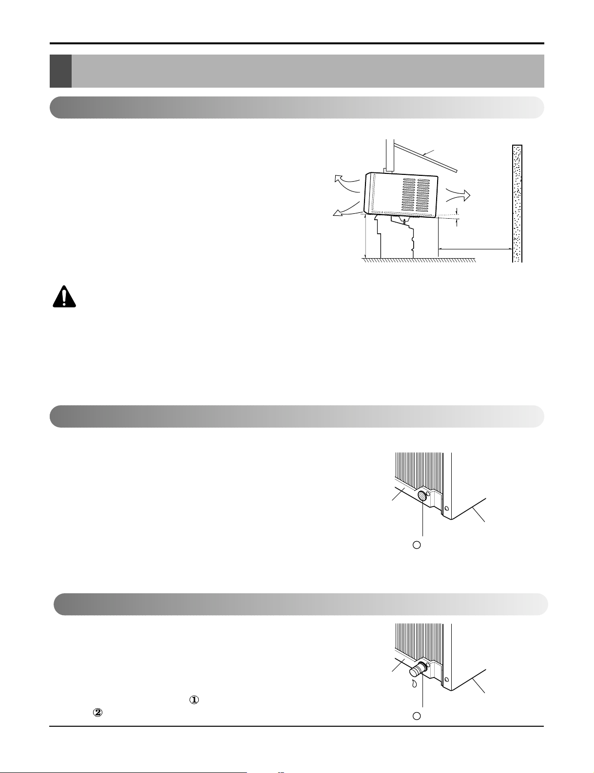
Figure 2
Figure 3
Figure 1
Installation
Installation
Select the Best Location
1.To prevent vibration and noise, make sure the unit
is installed securely and firmly.
2.Install the unit where the sunlight does not shine
directly on the unit.
3.The outside of the cabinet must extend outward for
at least 12" and there should be no obstacles, such
as a fence or wall, within 20" from the back of the
cabinet because it will prevent heat radiation of the
condenser.
Restriction of outside air will greatly reduce the
cooling efficiency of the air conditioner.
4.Install the unit a little slanted so the back is slightly
lower than the front (about1/2"). This will help force
con-densed water to the outside.
5.Install the unit from the bottom about 30"~60"
above the floor level.
The setting conditions must be checked prior to
initial starting.
The undermentioned items are especially important
checking points when the installation is finished.
1. Grounding wire (Green or Green and Yellow) is
provided in the power cord. The green wire must
be grounded.
2. Connect to a single-outlet 15A circuit.
(or 20A circuit for Electric Heater Model)
3. To avoid vibration or noise, make sure the air
conditioner is installed securely.
4 Avoid placing furniture or draperies in front of the
air inlet and outlet.
The air conditioner must be installed horizontally or
tilted slightly to the outside for proper water
drainage.
On exceptionally hot and humid days the air
conditioner may overflow condensed water.
If the air conditioner is used in hot and a high
humidity zone, exchange the HOLE RUBBER
for the DRAIN PIPE.(See figure 2, figure 3.)
Installation CheckInstallation Check
CAUTION: All side louvers of the cabinet must
remain exposed on the outdside of the structure.
COOLED AIR
30"~60"
AWNING
RADIATION
ABOUT 1/2"
FENCE
HEAT
Over 20"
How to Secure the Drain Pipe
BASE PAN
BASE PAN
1
HOLE RUBBER
2
HOLE RUBBER
BOTTOM
BOTTOM
Service ManSerSer ual vice Manvice Man 7ual ual Ser 77vice Manual 7
Page 8
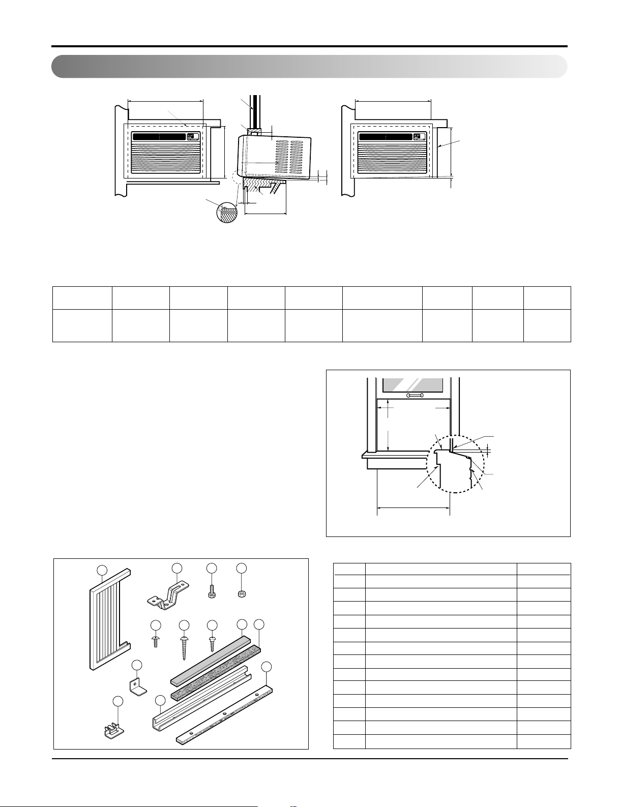
1. WHEN USING GASKET
2. WHEN USING INSTALLATION KITS
A. WINDOW REQUIREMENTS
This unit is designed for installation in
standard double hung windows with actual opening
widths from 25" to 36".
The top and bottom window sash must open
sufficiently to allow a clear vertical opening of 16"
from the bottom of the upper sash to the window
stool.
DEFROST
HEATCOOL
INDOORDESIRED
ENERGY
SAVER
AIR
PURYFIER
AUTO
RESTART
FAN
FAN
DRY
DEFROST
HEATCOOL
INDOORDESIRED
ENERGY
SAVER
AIR
PURYFIER
AUTO
RESTART
FAN
FAN
DRY
A
B
D
E
F
C
HJ
2
3
4
2
1
G
A
RIGHT SIDE
HORIZONTAL
LINE
B
1. WINDOW (WIDTH-A, HEIGHT-B)
2. GASKET
3. WALL
4. DETAILS 5.1 x 30 ROUND HEAD WOOD
SCREWS
ABCDE F HJK
535mm 366mm 250mm 30mm 0~25mm OVER 420mm 32 5~10mm 0~5mm
(211/2") (147/16") (10") (11/16") (0~1") (OVER 1617/32") (11/4") (3/16"~3/8") (0~3/16")
1
2 3 4
8 9
11
765
10
13
12
NO. NAME OF PARTS Q'TY
1 FRAME CURTAIN 2
2 SILL SUPPORT 2
3 BOLT 2
4 NUT 2
5 SCREW(TYPE A) 16
6 SCREW(TYPE B) 3
7 SCREW(TYPE C) 5
8 FOAM-STRIP 1
9 FOAM-PE 1
10 UPPER GUIDE 1
11 FOAM-PE 1
12 FRAME GUIDE 2
13
WINDOW LOCKING BRACKET
1
B. INSTALLATION KITS CONTENTS
25" to 36"
15" min
Stool
Interior wall
20
3
/32" min
(Without frame curtain)
Offset
1
/2" to 11/4"
Sill
Exterior
Installation
How to Install
8 Room Air Conditioner
Page 9
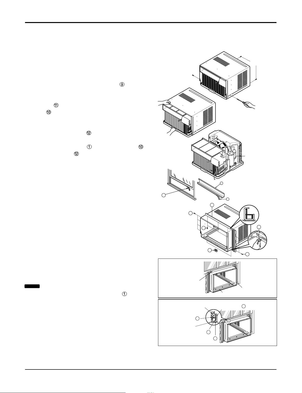
BEFORE INSTALLATION
1. Remove the screws which fasten the cabinet at
both sides and at the back.
2. Slide the unit out from the cabinet by gripping the
base pan handle and pulling forward while
bracing the cabinet.
3. Cut the window sash seal to the proper length. Peel
off the backing and attach the Foam-Pe to the
underside of the window sash.
4. Remove the backing from the top upper guide
Foam PE
and attach it to the bottom of the Upper
Guide
.
5. Attach the upper guide onto the top of the cabinet
with 3 type A screws.
6. Insert the Frame Guides into the bottom of the
cabinet.
7. Insert the Frame Curtain into the upper guide
and Frame Guides .
8. Fasten the curtains to the unit with 4 Type A screws
at the both sides.
NOW START INSTALLATION
1. Open the window. Mark a line on center of the
window stool (or desired air conditioner location).
Carefully place the cabinet on the window stool and
align the center mark on the front angle with the
center line marked in the window stool.
2. Pull the bottom window sash down behind the
upper guide until it meets.
Shipping
Screws
C
O
O
L
I
N
D
O
O
R
D
E
S
I
R
E
D
E
N
E
R
G
Y
S
A
V
E
R
A
I
R
P
U
R
Y
F
IE
R
A
U
T
O
R
E
S
T
A
R
T
F
A
N
F
A
N
D
R
Y
H
E
A
T
DEFROST
9
10
13
(Type A)
(Type A)
5
5
11
11
9
5
C
O
O
L
IN
D
OO
R
DESIRED
EN
ERG
Y
SAVER
AIR
PURYFIER
A
UTO
RE
STA
RT
F
A
N
FAN
D
R
Y
H
E
A
T
DEFRO
ST
EPS Material
Upper Guide
Window stool
Front Angle
Window Sash Upper guide
9
Frame Curtain
1
Foam-pe
10
Foam-pe
13
Cabinet
Figure 4
Figure 5
Service Manual 9
Installation
NOTICE
Do not pull the window sash down so tightly
that the movement of Frame Curtain is restricted.
Page 10
INDOOR OUTDOOR
Sill Support
Nut
Bolt
2
4
3
INDOOR OUTDOOR
12
7
5
Frame Guide
About 1/2"
Screw(Type A)
Cabinet
6
2
About 1/2"
Screw(Type B)5Screw(Type A)
Sill support
Type C
Sash track
Front Angle
Screw(Type B)
6
Sill support
2
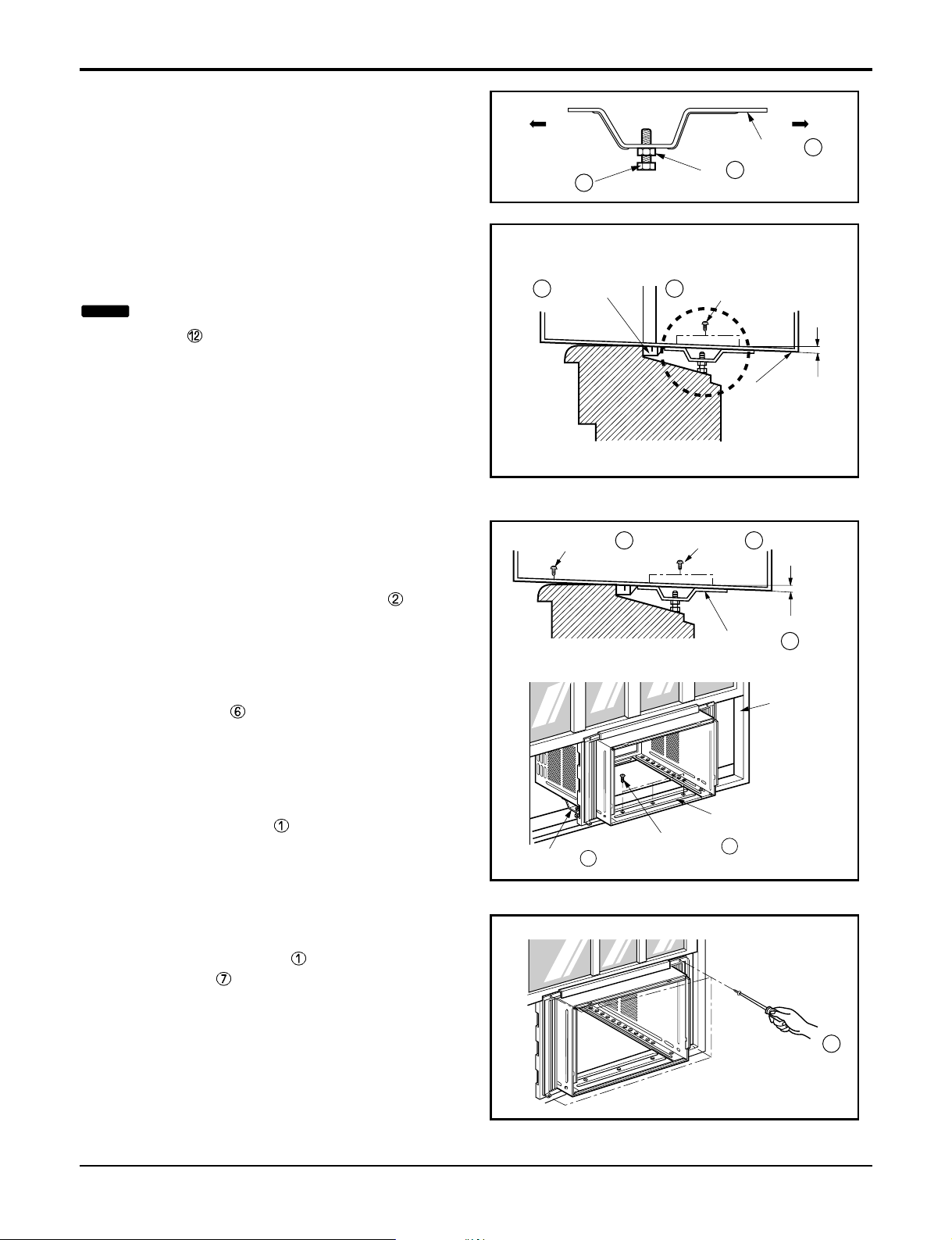
3. Loosely assemble the sill support using the parts
in
Figure
6.
4. Select the position that will place the sill
support near the outer most point on sill
(See
Figure
6)
5. Attach the sill support to the cabinet track hole in
relation to the selected position using
2 Type A screws in each support (See
Figure 7).
6. The cabinet should be installed with a very slight
tilt (about
1
/2") downward toward the outside
(See Figure 8).
Adjust the bolt and the nut of Sill Support for
balancing the cabinet.
7. Attach the cabinet to the window stool by
driving the screws (Type B: Length sixteen
millimeters and below.) through the front angle into
window stool (5/8").
8. Pull each Frame Curtain properly to each
window sash track, and repeat step 2.
9. Attach each Frame Curtain to the window sash
by using screws (Type C).
(See Figure 9)
Figure 6
Figure 7
Figure 8
Figure 9
10 Room Air Conditioner
Installation
NOTICE
Be careful when you install the cabinet (frame
guides are broken so easily).
Page 11
DEFROST
HEATCOOL
INDOOR DESIRED
ENERGY
SAVER
AIR
PURYFIER
AUTO
RESTART
FAN
FAN
DRY
Screw(Type A)
Screw(Type A)
Power cord
13
8
Foam-Strip
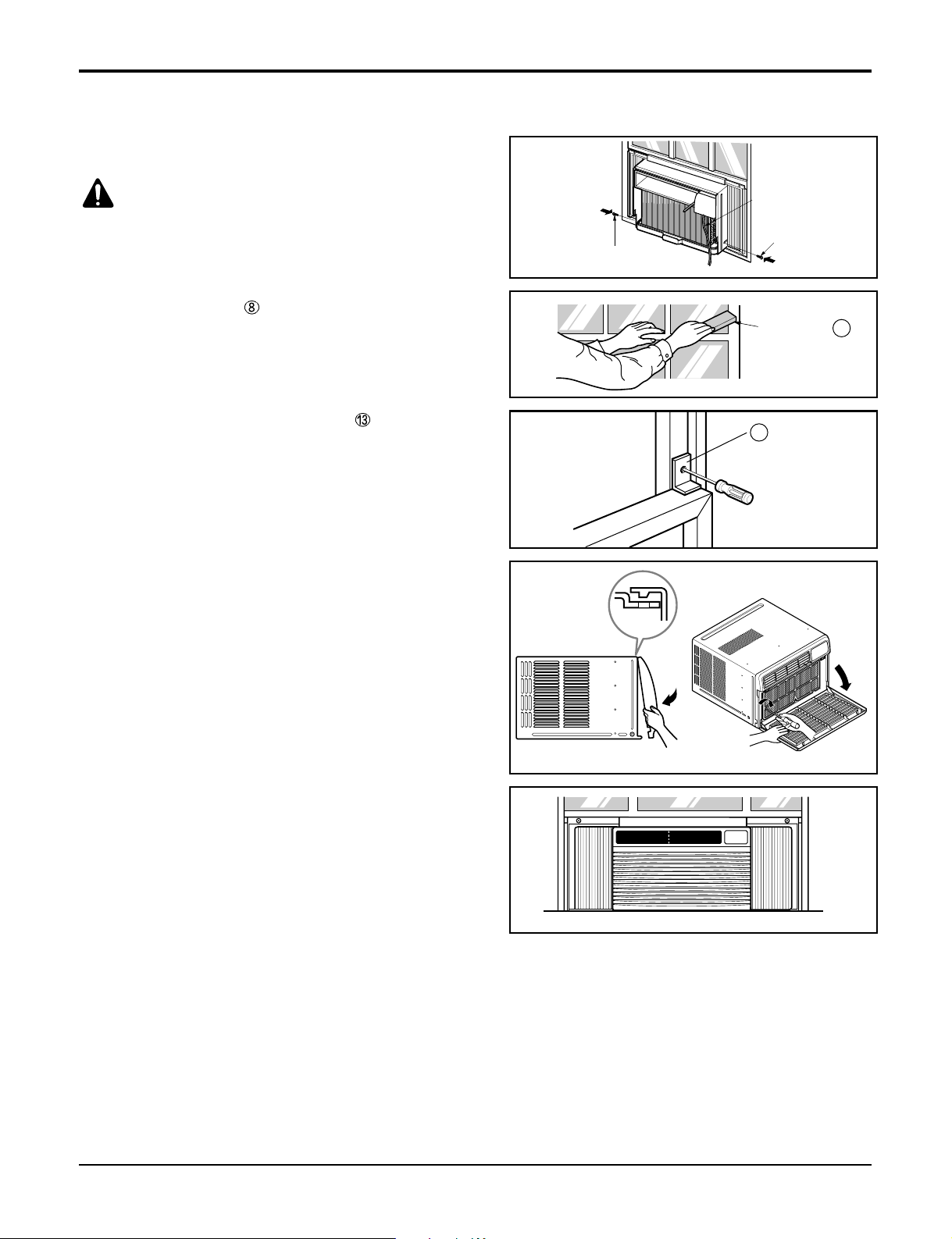
10. Slide the unit into the cabinet.(See Fig. 10)
11. Cut the Foam-Strip to the proper length and insert
between the upper and lower window sash.
(See Fig. 11)
12. Attach the window Locking Bracket with a type C
screw. (See Fig. 12)
13. Attach the front grille to the cabinet by inserting the
tabs on the grille into the tabs on the front of the
cabinet. Push the grille in until it snaps into
place.(See Fig. 13)
14. Lift the inlet grille and secure it with a type A screw
through the front grille.(See Fig. 14)
Figure 10
Figure 11
Figure 12
Figure 15
Figure 14
Figure 13
Service Manual 11
Installation
CAUTION: For security purpose, reinstall screws
(Type A) at cabinet's sides.
Page 12
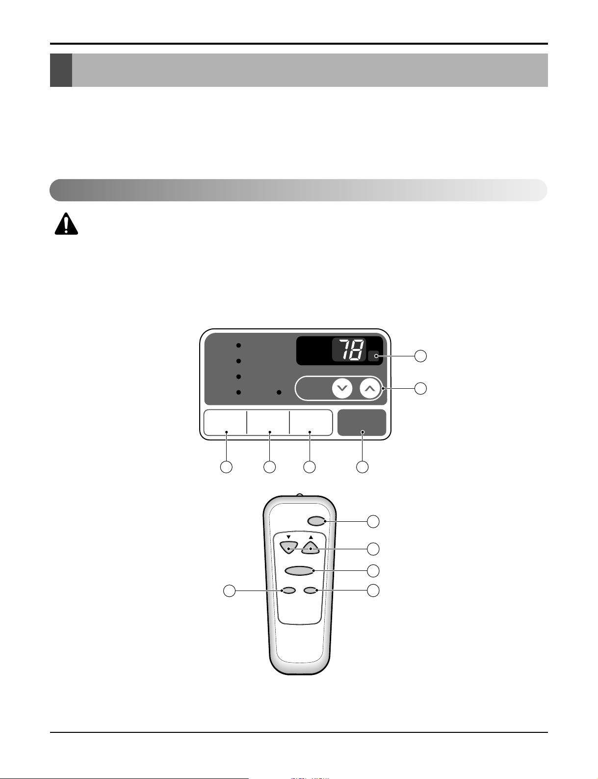
The controls look like this:
Controls
Remote Control Operations
CAUTION: The Remote Controller will not function properly if strong light strikes
the sensor window of the air conditioner or if there are obstacles between the
Remote Controller and the air conditioner.
12 Room Air Conditioner
Installation
• Designed for COOLING ONLY.
• Powerful and quiet cooling.
• Slide-in and slide-out chassis for the simple
installation and service.
• Low air-intake, top cooled-air discharge.
• Built-in adjustable Thermistor
• Washable one-touch filter
• Compact size
• Reliable and efficient rotary compressor is
equipped.
Powe r
Temp
Fan Speed
Timer Mode
1
2
3
4
5
'
F
TIMER POWERMODE
TEMP
FAN
SPEED
F1 LOW
F2 MED
F3 HIGH
Dry Timer
Fan
Energy
Saver
Cool
1
2
6
3 45
Operation
Page 13
Service Manual 13
Operation
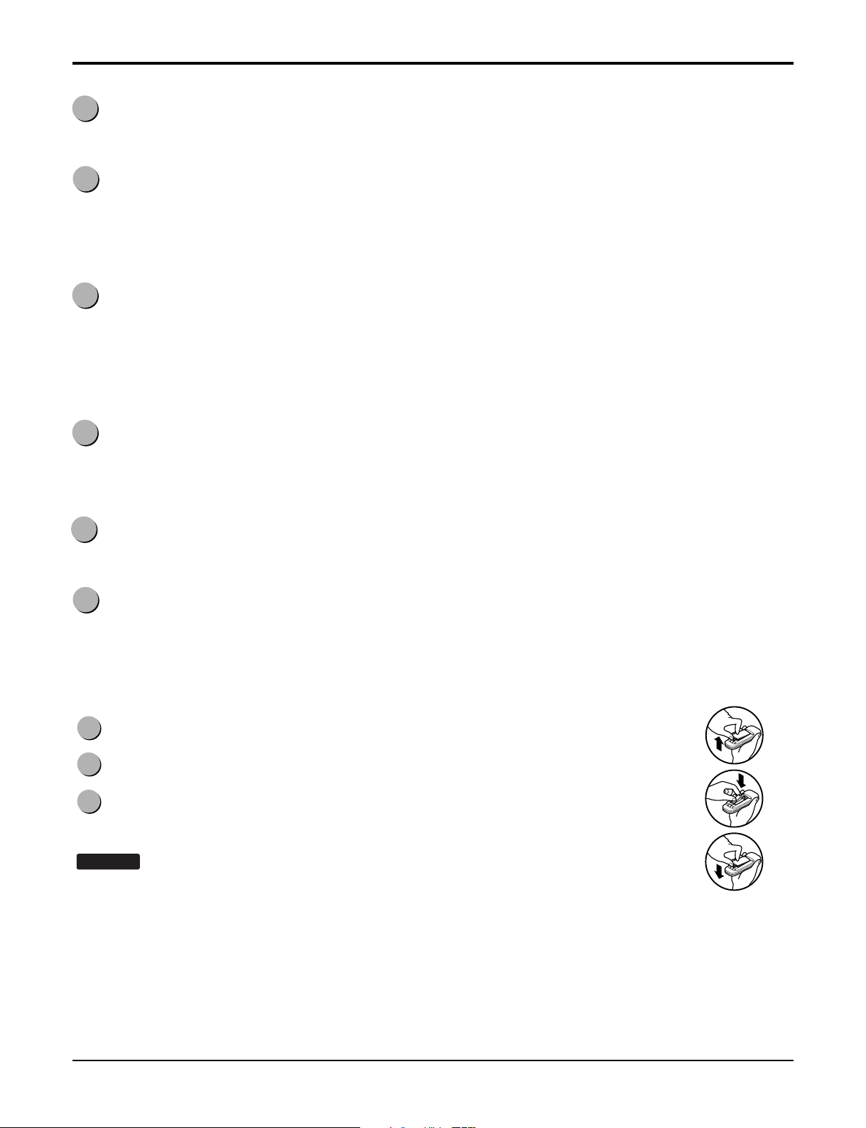
How to Insert Batteries
1
POWER
Operation starts when this button is pressed and stops when you press the button again.
2
TEMPERATURE CONTROL
The thermostat monitors room temperature to maintain the desired temperature.
The thermostat can be set between 60°F~86°F (16°C~30°C).
The unit takes an average of 30 minutes to adjust the room temperature by 1°F.
3
OPERATION MODE SELECTOR
Select cooling mode to cool the room.
Select energy saver mode for energy saving operation.
Select fan mode for basic ventilating fan operation.
Select dry mode for dry operation.
4
FAN SPEED SELECTOR
For increased power while cooling, select a higher fan speed.
3 steps: High ➔ Low ➔ Med
5
ON/OFF TIMER
The timer can be set to start and stop the unit in hourly increments (up to 12 hours).
6
REMOTE CONTROL SENSOR
1
Push out the cover on the back of the remote control with your thumb
2
Pay attention to polarity and insert two new AAA 1.5V batteries.
3
Reattach the cover.
NOTICE
• In order to prevent discharge, remove the batteries from the remote control if the air
conditioner is not going to be used for an extended period of time
Keep the remote control away from extremely hot or humid places.
To maintain optimal operation of the remote control, the remote sensor should not be
exposed to direct sunlight.
:
Do not use rechargeable batteries. Make sure that both batteries are new.
Page 14

14 Room Air Conditioner
Disassembly
Disassembly
Mechanical Parts
— Before the following disassembly, POWER SWITCH set to OFF and disconnect the power cord.
1. FRONT GRILLE
1. Open the lnlet grille downward and remove the air
filter.
2. Remove the screw which fastens the front
grille.(See Figure 16)
3. Pull the front grille from the right side.
4. Remove the front grille.(There are 4 hooks.)
5. Re-install the components by referring to the
removal procedure, above.
2. CABINET
1. After disassembling the FRONT GRILLE, remove
the 2 screws which fasten the cabinet at both
sides.
2. Remove the 2 screws which fasten the cabinet at
back.
3. Pull the base pan forward. (See Figure 17)
4. Remove the cabinet.
5. Re-install the components by referring to the
removal procedure, above.
Figure 16
3. CONTROL BOX
1. Remove the front grille.
2. Remove the cabinet.
3. Remove the 2 screws which fasten the power
cord.
4. Disconnect the grounding screw from the
evaporator channel.
5. Remove the 1 screw which fasten the control box
cover.
6. Remove the housing which connects PCB and
motor wire in the control box.
7. Disconnect the housing which connects Plazma
Air Purifier.(Optional)
8. Remove the screw at left cover of filter case and
open the cover to remove inner screw. (Optional)
9. Remove the nut which fastens the terminal cover.
10. Remove the terminal cover.
11. Remove all the leads from the overload protector.
12. Discharge the capacitor by placing a 20,000
ohmresistor across the capacitor terminals.
13. Raise the control box upward completely.
(See Figure 18)
14. Re-install the components by referring to the
removal procedure, above.
(Refer to the circuit diagram found on page 22 in
this manual and on the control box.)
Figure 17
Figure 18
COOL
FAN
DRY
HEAT
FAN
D
IN
E
F
D
R
O
O
O
S
R
T
D
E
S
E
IR
N
E
E
D
R
S
G
A
Y
V
E
R
A
P
IR
U
R
Y
F
IE
A
R
U
R
T
E
O
S
T
A
R
T
Page 15

Service Manual 15
Disassembly
Air Handling Parts
4. AIR GUIDE AND TURBO FAN
1. Remove the front grille.
2. Remove the cabinet.
3. Remove the control box.
4. Remove the 4 screws which fasten the brace.
5. Remove the brace.
6. Remove the 2 screws which fasten the air guide
upper.
7. Remove the air guide upper.(See figure 19)
8. Remove the 2 screws which fasten the evaporator.
9. Move the evaporator forward and pulling it upward
slightly. (See Figure 20)
10. Pull out the hook of orifice by pushing the tabs
and remove it. (See Figure 21)
11. Remove the clamp with a hand plier which
secures the turbo fan.
12. Remove the turbo fan.
13. Remove the 2 screws which fasten the air guide
from the base pan.
14. Move the air guide backward, and pull out from
the base pan.(Move the air giude lower carefully.)
15. Re-install the components by referring to the
removal procedure, above.
5. FAN
1. Remove the cabinet.
2. Remove the brace.
3. Remove the 5 screws which fasten the condenser.
4. Move the condenser to the left carefully.
5. Remove the clamp which secures the fan.
6. Remove the fan. (See Figure 22)
7. Re-install by referring to the removal procedure.
Figure 19
Figure 20
Figure 21
Figure 22
Page 16

16 Room Air Conditioner
Disassembly
6. SHROUD
1. Remove the fan.
2. Remove the shroud. (See Figure 23)
3. Re-install the components by referring to the
removal procedure, above.
1. OVERLOAD PROTECTOR
1. Remove the cabinet.
2. Remove the nut which fastens the terminal cover.
3. Remove the terminal cover. (See Figure 24)
4. Remove all the leads from the overload protector.
5. Remove the overload protector.
6. Re-install the components by referring to the
removal procedure, above.
2. COMPRESSOR
1. Remove the cabinet.
2. Discharge the refrigerant system using a Freon
TM
Recovery System.
If there is no valve to attach the recovery system,
install one (such as a WATCO A-1) before venting
the FreonTM. Leave the valve in place after
servicing the system.
3. Remove the overload protector.
4. After purging the unit completely, unbraze the
suction and discharge tubes at the compressor
connections.
5. Remove the 3 nuts and the 3 washers which
fasten the compressor.
6. Remove the compressor. (See Figure 25)
7. Re-install the components by referring to the
removal procedure, above.
Figure 23
Figure 24
Figure 25
Electrical Parts
Page 17

Service Manual 17
Disassembly
3. CAPACITOR
1. Remove the control box.
2. Open the top cover from the control box.
(See Figure 26)
3. Pull out the capacitor from the control box.
4. Disconnect all the leads of capacitor terminals.
5. Re-install the components by referring to the
removal procedure, above.
4. POWER CORD
1. Remove the control box.
2. Open the top cover from the control box.
3. Disconnect the front panel from the control box.
(See Figure 27)
4. Disconnect two leads from the capacitor and relay.
5. Pull out the power cord.
6. Re-install the component by referring to the above
removal procedure, above.
(Use only one ground-marked hole for ground
connection.)
7. If the supply cord of this appliance is damaged, it
must be replaced by the special cord.
(The special cord means the cord which has the
same specification marked on the supply cord
attached at the unit.)
DEFROST
HEAT
C
O
O
L
IN
D
O
O
R
D
E
S
IR
E
D
E
N
E
R
G
Y
S
A
V
E
R
A
IR
P
U
R
Y
F
IE
R
A
U
T
O
R
E
S
T
A
R
T
F
A
N
FAN
D
R
Y
H
E
A
T
D
E
F
R
O
S
T
Figure 27
Figure 26
Page 18

Disassembly
5. MOTOR
1. Remove the cabinet.
2. Remove the turbo fan.
3. Remove the fan.
4. Remove the 4 screws which fasten the motor from
the air guide. (See Figure 28)
5. Remove the motor.
6. Re-install the components by referring to the
removal procedure, above.(See Figure 28)
1. CONDENSER
1. Remove the cabinet.
2. Remove the 5 screws which fasten the
brace.
3. Remove the 5 screws which fasten the condenser
and shroud.
4. After discharging the refrigerant completely,
unbraze the interconnecting tube at the condenser
connections.
5. Remove the condenser.
6. Re-install the components by referring to notes.
(See Figure 29)
2. EVAPORATOR
1. Remove the control box.
2. Remove the air guide upper.
3. Remove the 2 screws which fasten the evaporator.
4. Move the evaporator sideways carefully.
5. After discharging the refrigerant completely,
unbraze the interconnecting tube at the evaporator
connections.
6. Remove the evaporator.
7. Re-install the components by referring to notes.
(See Figure 30)
Figure 28
Figure 29
Figure 30
Refrigerating Cycle
CAUTION: Discharge the refrigerant system using a Freon
to attach the recovery system, install one (such as a WATCO A-1) before venting the FreonTM. Leave
the valve in place after servicing the system.
TM
Recovery System. If there is no valve
18 Room Air Conditioner
Page 19

3. CAPILLARY TUBE
CAUTION: If high vacuum equipment is used, just crack valves A
and B for a few minutes, then open
slowly with the two full turns counterclockwise. This will keep oil from foaming
and being drawn into the vacuum pump.
1. Remove the cabinet.
2. After discharging the refrigerant completely,
unbraze the interconnecting tube at the capillary
tube.(See caution above)
NOTES
— Replacement of the refrigeration cycle.
1. When replacing the refrigeration cycle, be sure to
Discharge the refrigerant system using a Freon
recovery System.
If there is no valve to attach the recovery system,
install one (such as a WATCO A-1) before venting
the FreonTM. Leave the valve in place after
servicing the system.
2. After discharging the unit completely, remove the
desired component, and unbraze the pinch-off
tubes.
3. Solder service valves into the pinch-off tube ports,
leaving the valves open.
4. Solder the pinch-off tubes with Service valves.
5. Evacuate as follows.
1) Connect the vacuum pump, as illustrated figure
31A.
2) Start the vacuum pump, slowly open manifold
valves A and B with two full turns
counterclockwise and leave the valves open.
The vacuum pump is now pulling through valves
A and B up to valve C by means of the manifold
and entire system.
3) Operate the vacuum pump for 20 to 30 minutes,
until 600 microns of vacuum is obtained. Close
valves A and B, and observe vacuum gauge for
a few minutes. A rise in pressure would
indicate a possible leak or moisture remaining in
the system. With valves A and B closed, stop
the vacuum pump.
4) Remove the hose from the vacuum pump and
place it on the charging cylinder. See figure
31B.
Open valve C.
Discharge the line at the manifold connection.
5) The system is now ready for final charging.
TM
Disassembly
3. Remove the capillary tube.
4. Re-install the components by referring to notes.
6. Recharge as follows :
1) Refrigeration cycle systems are charged from
the High-side. If the total charge cannot be put
in the High-side, the balance will be put in the
suction line through the access valve which you
installed as the system was opened.
2) Connect the charging cylinder as shown in figure
31B.
With valve C open, discharge the hose at the
manifold connection.
3) Open valve A and allow the proper charge to
enter the system. Valve B is still closed.
4) If more charge is required, the high-side will not
take it. Close valve A.
5) With the unit running, open valve B and add the
balance of the charge.
a. Do not add the liquid refrigerant to the Low-
side.
b. Watch the Low-side gauge; allow pressure to
rise to 30 lbs.
c. Turn off valve B and allow pressure to drop.
d. Repeat steps b. and c. until the balance of the
charge is in the system.
6) When satisfied the unit is operating correctly,
use the pinch-off tool with the unit still running
and clamp on to the pinch-off tube. Using a tube
cutter, cut the pinch-off tube about 2 inches from
the pinch-off tool. Use sil-fos solder and solder
pinch-off tube closed. Turn off the unit, allow it to
set for a while, and then test the leakage of the
pinch-off connection.
Service Manual 19
Page 20

Disassembly
Equipment needed: Vacuum pump, Charging cylinder, Manifold gauge, Brazing equipment. Pin-off tool capable
of making a vapor-proof seal, Leak detector, Tubing cutter, Hand Tools to remove components, Service valve.
A
COMPOUND GAUGE
EVAPORATOR
(LOW PRESSURE SIDE)
COMPRESSOR
CAPILLARY TUBE
CONDENSER
(HIGH PRESSURE SIDE)
SEE INSETS
BELOW
MANIFOLD
GAUGE
B
Figure 31A-Pulling Vacuum
Figure 31B-Charging
A
B
EXTERNAL
VACUUM PUMP
A
CHARGING
CYLINDER
LOW
HI
B
C
20 Room Air Conditioner
Page 21

Service Manual 21
Schematic Diagram
Schematic Diagram
33
22
11
HVB
5V
b
c
R04P
X
O
O
X
5V
R04P
8
EEPROMModel
1
EEPROM
A0
5V
S7136
IC01A
3.6V
2
1
R01A
20K
3
+
10V
1uF
C02A
CAT93C46
Vcc
Auto Restart
Non Auto Restart
20K
R03P
20K
576
R02P
Q03G
1K
R04P
A101S
Q01G
A101S
Q02G
SW03G
D03G
SW06G
D06G
TEMP UP
D02G
D05G
SW02G
MODE
SW05G
TEMP DOWN ON/OFF
D01G
D04G
FAN
SW01G
TIMER
SW04G
A101S
423
A2
GND
A1
10K
R06P
R05P
10K
Rx
SDA
SCL
Digit4 (Scan4)
0.001
C01F
R01F
10K
C02F
0.001
R03F
10K
Digit1 (Scan1)
SEG-c
SEG-a
SEG-b
Digit0 (Scan0)
Digit2 (Scan2)
Digit3 (Scan3)
SCL
SDA
WP
0.01
C01A
50V
1M
R01B
OSC01B
RT8.00MG
1%
12.1K
R02H
6.2K
1%
R04H
5V
2
1
CN-TH1
SMAW200-02
2
112
5V
12
TEST
14 13
8
9
10
11
1619 18
VSS
VAref
17 15
Osc in
Osc out
/Reset
21 2022
242526
23
5V
4WAY
SYNC
LOW
COMP
Pipe TH
Option1
Option2
Room TH
567
123
4
MICOM
TMP87CH47U
SEG-d
44
SEG-e
SEG-f
4342
VDD
40
SEG-g
3837
KEY0
39
SLIDE SW
41
27282931323330
ION
MED
HI
Receiver
LED out3
Buzzer
363534
LED out0
LED out1
LED out2
KEY1
HVB
R22H
1%
12.1K
R21H
12.1K
1%
OR2H
745
6
987
OR1H
131211
10
5V
1
2
9
8
IC01M
1K
R02E
20
GND
Vout
RECEIVER
Vcc
R01L
5
4
12V
+
5V
10V
220
C02L
ULN2004A
161514
3
6
680pF
C01L
R01P
20K
50V
3
Digit0
510
a
f
a
b
Digit1
a
3
9
b8c
d
f
d
e
d
c
7
e4f1g
e
6
g g
COOL
DEFROST
DRY/HEAT
TIMER
FAN
E/SAVER
R02G
R03G
R04G
R01G
680
680
680
680
R05G
R06G
R07G
12V
680
680
680
IC01G
151413
432
161
121110
765
98
ULN2004A
10K
5V
5V
R12F
R01E
1K
5V
C06D
BZ01E
PKM13EPY
-4002
+
C05D
50V
10V
220
0.01
10
12V
11
12
CN-AC/DC
51581-12(YEONHO)
52044-1245(MOLEX)
C05D
5V
12V
I
C04D
O
7805
IC02D
25V
25V
0.01
0.01
ANGLE
11
12
Rx
Tx
1K
Q03T
C104M
5V
5V
Q02T
A104M
Q01T
C104M
Q04T
A104M
C03T
0.001
R01T
25V
C02T
0.001
D01T
1N4148
C01T
0.1
50V
5V
(RD)
CN-TELE
CN-TH2
SMW200-03
SMW250-02
465
J7
RY-COMP
RY-4WAY
RY-LOW
9
8
CN-TH2
X
O
X
O
J07
O
X
X
O
RY-4WAY
RY-MED
RY-HI
CN-4WAY
7
J5
2
2
PIPE-TH
2
2
1
1
3
3
1
1
2
2
SW2
CN-HVB
SMW200-03(BL)
CN-CONT
SMW200-03(YL)
Model
RY-4WAY
3
3
3
3
1
1
2
2
SW1
33
11
CN-4WAY
YW396-03AV(YL)
SMW200-03(WH)
CN-12V
12V
Cool Only
Heat Pump
1
1
10
S/V-
4WAY
35V2
1
12V
CN-AC/DC
51580-12
52045-1245
+
I
7812
IC01D
C03D
C01D
D04D
+
O
C02D
16V
35V
50V
1000
1000
0.1
4
7
D02D
D03D
2
1
POWER TRANS
1N4004
D02D~D05D
D05D
STRAIGHT
RY-HI
RY-MED
RY-LOW
R01J
C01J
0.1/275V
1
3
1
3
579
579
33
11
CN-PWR
CN-MOTOR
YW396-09AV
YW396-03AV
SVC271D-14A
ZNR01J
SVC271D-14A
RY-COMP
G4A-1A-E-LG
FUSE
250VT3.15A
120 1/2W
CAPACITOR
C
MAIN POWER
MOTOR
FAN
COMP
FAN
HERM
ROOM-TH
88 SEGMENT
Electronic Control Device
Page 22

22 Room Air Conditioner
Schematic Diagram
Wiring Diagram
MOTOR ASSY
CAPACITOR
COMPRESSOR
OVERLOAD PROTECTOR
DC PCB ASSEMBLY
AC PCB ASSEMBLY
THERMISTOR
PLASMA FILTER ASSY
1
2
3
4
5
6
7
8
1
1
1
1
1
1
1
1
S
S
S
S
S
S
S
S
LOCATION
NO.
DESCRIPTION
REMARKS
Q'TY
PER SET
MOTOR
COMP.
CAPACITOR
DC PCB
ASSEMBLY
THERMISTOR
AIR FILTER
ASSEMBLY
AC PCB
ASSEMBLY
WIRING DIAGRAM
SWITCH
H.V.
ASSEMBLY
BK
CN-MOTOR
CN-PWR
DC12V
ZNR01J
CN-12V
CN-HVB
RY-COMP
3
4
FUSE
250V/T2A
RY-LOW
RY-MED
RY-HI
CN-AC/DC
POWER
TRANS
CN-AC/DC
CN-TH1
BL
RD
RDBK
BL
R
S
C
OLP
YL
OR
YL
F
C
H
WH
(BL)
(
Ribbed
)
BK(BR
)
(
Plain
)
GN/YL
(GN)
GN/YL
(GN)
BK
RD
OR(BR
)
1
5
7
6
8
4
2
3
S: Service Parts
N: Non Service Parts
Page 23

Service Manual 23
Schematic Diagram
Components Location
1. MAIN P.C.B ASSEMBLY
2. DISPLAY P.C.B. ASSEMBLY
R01T
Q01T
CN-CONCN-12V
CN-AC/DC
J1
J5
D02D
D03D
CN-HVB
HEAT SINK
D04D
C03T
D05D
IC01D
C01D
Q02T
J4
Q03T
C02D
J6
D01T
C02T
QIC02DT
J2
C04D
CN-TELE
Q04T
J3
C05D
J7
RY-HI
RY-MEDRY-LOWRY-4WAY
CN-TH2
CN-PWR
ZNR01J
R01J
PCB:6870A90068D
E03J
E02JJ8E01J
CN-MOTOR
CN-4WAY
C01J
RY-COMP
ASSEMBLY:6871A20417C
POWER
TRANS
FUSE
250V/T3.15A
PCB:6870A90067C
ASSEMBLY:6871A20418A
E04J
E05J
Page 24

Troubleshooting Guide
Troubleshooting Guide
Piping System
Figure 32 is a brief description of the important components and their function in what is called the refrigeration
system. This will help you to understand the refrigeration cycle and the flow of the refrigerant in the cooling cycle.
MOTOR
COMPRESSOR
OIL
(LIQUID REFRIGERANT)
CAPILLARY TUBE
OUTSIDE COOLING
AIR FOR REFRIGERANT
PASS THROUGH
SUCTION LINE
COOL LOW PRESSURE VAPOR
COOLED
AIR
COMPLETE LIQUID
BOIL OFF POINT
LIQUID
PRESSURE
DROP
ROOM AIR HEAT LOAD
VAPOR INLET
HOT
DISCHARGED
AIR
LIQUID OUTLET
HIGH PRESSURE VAPOR
LIQUID REFRIGERANT
LOW PRESSURE VAPOR
ROOM AIR CONITIONER
EVAPORATOR COILS CONDENSER COILS
CYCLE OF REFRIGERATION
Figure 32
24 Room Air Conditioner
CONDENSER COIL
FAN
CAPILLARY TUBE
MOTOR
COMPRESSOR
TURBO FAN
EVAPORATOR COIL
Page 25

Troubleshooting Guide
Troubleshooting Guide
In general, possible trouble is classified in two kinds.
The one is called Starting Failure which is caused from an electrical defect, and the other is ineffective Air
Conditioning caused by a defect in the refrigeration circuit and improper application.
Unit runs but poor cooling.
Ineffective Cooling
Check outdoor coil
(heat exchanger) & the fan
operation.
Check gas leakage.
Repair gas leak.
Replacement of unit if the
unit is beyond repair.
Satisfactory operation with
temperature difference of
inlet & outlet air ;
44~50°F(7~10°C)
Check heat load
increase.
Clean condenser.
Not on separate circuit.
Check inside gas
pressure.
Adjusting of refrigerant
charged.
Malfunction of compressor.
Replacement of
compressor.
Check cold air circulation
for smooth flow.
Dirty indoor coil
(Heat exchanger)
Correct above trouble
Check clogging in refrigeration circuit.
Repair clogging in refrigeration circuit.
Obstruction at air outlet
Clogged of air filter.
Malfunction of fan
Service Manual 25
Page 26

Troubleshooting Guide
Fails to Start
Check circuit breaker
and fuse.
Gas leakage of feeler bulb
of thermostat
Check of control switch.
Fan only fails to start.
Improper wiring.
Defect of fan motor
capacitor.
Irregular motor resistance
(
).
Irregular motor insulation
(
).
Replacement of fan motor.
Regular but fails to start.
Replacement of compressor
(locking of rotor, metal).
Improper thermostat setting.
Loose terminal connection.
Improper wiring.
Irregular motor resistance ( )
Irregular motor insulation ( )
Replacement of compressor
(Motor damaged)
Drop of power voltage.
Capacitor check.
Replacement
Compressor only fails to
start.
Defect of compressor
capacitor.
Check of power source.
Check of control switch
setting.
26 Room Air Conditioner
Page 27

Troubleshooting Guide
• Check the Fuse.
• Check the wiring diagram.
Is the
Trans input power AC 115V?
Is the Trans output power
about AC 14V?
Is shorted the Trans. output?
Is output Voltage of IC01D
DC 12V?
Is output Voltage of IC02D
DC 5V?
Is the voltage No.18 of Micom
DC 5V?
Replace AC PCB Ass'y.
Is the
connection between
AC and DC
OK?
Is the reset circuit good?
(The No.14 of
Micom is 5V.)
• Check the Fuse.
• Check the wiring diagram.
• Check the Main
PCB pattern.
• Replace the Trans.
•
Replace
D02D~D05D.
• Replace IC01D.
• Replace IC02D.
•
Replace
IC01A, C02A.
• Connect connector
exactly.
• Check the PCB
pattern.
NO
NO
NO
NO
NO
NO
NO
YES
YES
YES
YES
YES
YES
YES
NO
YES
Possible Trouble 1 The unit does not operate.
Electrical Parts Troubleshooting Guide
Service Manual 27
Page 28

Troubleshooting Guide
Possible Trouble 2 The compressor does not operate.
Possible Trouble 3 The compressor always operate.
Is setting
Temp. set lower than Room
Temp.-0.5°C?
Is the voltage No.10
of IC01M 0V?
• Replace IC01M.
• Select the setting Temp. to lower Number.
• Wait 3 Minutes.
Does the Unit delay
for 3 minutes?
• Replace MAIN
PCB Ass'y.
Is the voltage N0.9 of
IC01M DC 12V?
• Check the RY-COMP.
• Check the wiring
Diagram.
NO
NO
NO
YES
YES
YES
YES
Is the wire connection of
RY-COMP OK?
• Check the RY-COMP.
• Connect LEAD Wire to
RY-COMP again.
NO
YES
NO
28 Room Air Conditioner
Page 29

Troubleshooting Guide
Possible Trouble 4 FAN does not operate.
Possible Trouble 5
The function of Energy Saver does not operate.
• Replace IC01M.
• Replace IC01M.
Is the voltage NO.1 or 2 or 4
of IC01M DC 12V?
Is the voltage NO.16 or 15 or 13
of IC01M 0V?
• Check the RY-Hi or
RY-Med or RY-Lo.
•
Check the wiring diagram.
NO
NO
YES
YES
NO
NO
YES
YES
Is the mode
key pushed once more from
cool mode?
Is the voltage No.3 of
CN-AC/DC of AC PCB
Ass'y DC 5V?
• Reference to
OWNER'S MANUAL.
• Set the mode key to
Energy Saver mode.
• Check the Energy
Saver mode key.
• Check the pattern of
AC & DC PCB.
Service Manual 29
Page 30

30 Room Air Conditioner
Troubleshooting Guide
Possible Trouble 6 Remote controller does not operate.
Possible Trouble 7 It displays abnormally on DC PCB Ass’y.
NO
NO
NO
NO
YES
YES
YES
Is IC01G good?
Is the connection of
CN-AC/DC
OK?
• Replace the DC
PCB Ass'y.
• Replace IC01G.
• Replace IC03G
(Q01G, Q02G, Q03G
for Delux Model).
• Connect connector
to
CN-AC/DC
exactly.
Does the IC03G
(Q01G, Q02G, Q03G for Delux Model)
operate normally on DC
PCB Ass'y?
• Check the PCB pattern.
Is the voltage of Battery
over 2.3V?
• Replace Receiver Ass'y.
Is the connection of
CN-AC/DC
OK?
Is the voltage No.10
of CN-AC/DC on DC PCB
Ass'y DC 5V?
• Replace the battery.
• Check the PCB pattern.
• Connect connector to
CN-AC/DC
exactly.
NO
NO
NO
YES
YES
YES
Page 31

• Check the Fuse.
• Check the wiring diagram.
Is the
Trans input power AC 115V?
Is the Trans output power
about AC 14V?
Is shorted the Trans. output?
Is output Voltage of IC01D
DC 12V?
Is output Voltage of IC02D
DC 5V?
Is the voltage No.40 of Micom
DC 5V?
Replace AC PCB Ass'y.
Is the
connection between
AC and DC
OK?
Is the reset circuit OK?
(The No.14 of
Micom is 5V.)
• Check the Fuse.
• Check the wiring diagram.
• Check the AC
PCB pattern.
• Replace the Trans.
•
Replace
D02D~D05D.
• Replace IC01D.
• Replace IC02D.
•
Replace
IC01A, C01A.
• Connect connector
exactly.
• Check the PCB
pattern.
NO
NO
NO
NO
NO
NO
NO
YES
YES
YES
YES
YES
YES
YES
NO
YES
Possible Trouble 1 The unit does not operate.
Electrical Parts
Troubleshooting Guide
Service Manual 31
Page 32

Possible Trouble 2 The compressor does not operate.
Possible Trouble 3 The compressor always operate.
Is desired
Temp. set lower than Room
Temp.-0.5°C?
Is the voltage No.10
of IC01M 0V?
• Replace IC01M.
• Select the desired Temp. to lower Number.
• Wait 3 Minutes.
Is the Unit for 3 minutes
delay?
• Replace AC
PCB Ass'y.
Is the voltage N0.9 of
IC01M DC 12V?
• Check the RY-COMP.
• Check the wiring
Diagram.
NO
NO
NO
YES
YES
YES
YES
Is the wire connection of
RY-COMP OK?
• Check the RY-COMP.
• Connect LEAD Wire to
RY-COMP again.
NO
YES
NO
32 Room Air Conditioner
Troubleshooting Guide
Page 33

Possible Trouble 4 FAN does not operate.
Possible Trouble 5
Remote controller does not operate.
• Replace IC01M.
• Replace IC01M.
Is the voltage NO.1 or 2 or 4
of IC01M DC 5V?
Is the voltage NO.16 or 15 or 13
of IC01M 0V?
• Check the RY-Hi or
RY-Med or RY-Lo.
•
Check the wiring diagram.
NO
NO
YES
YES
• Check the PCB pattern.
Is the voltage of Battery
over 2.3V?
• Replace Receiver Ass'y.
Is the connection of
CN-AC/DC OK?
Is the voltage No.10
of CN-AC/DC on AC PCB
Ass'y DC 5V?
• Replace the battery.
• Check the PCB pattern.
• Connect connector to
CN-AC/DC exactly.
NO
NO
NO
YES
YES
YES
Service Manual 33
Troubleshooting Guide
Page 34

Possible Trouble 6 It displays abnormally on DC PCB Ass’y.
NO
NO
NO
NO
YES
YES
YES
Are IC01G and IC02G
OK?
Is the connection of
CN-AC/DC OK?
• Replace the DC
PCB Ass'y.
• Replace IC01G,
IC02G.
• Replace IC03G.
• Connect connector
to CN-AC/DC exactly.
Does the IC03G
operate normally on AC
PCB Ass'y?
34 Room Air Conditioner
Troubleshooting Guide
Page 35

COMPLAINT CAUSE REMEDY
Check voltage at outlet. Correct if none.
Check voltage to Control Box. If none, check power
supply cord. Replace cord if circuit is open.
Connect wire. Refer to wiring diagram for terminal
identification. Repair or replace loose terminal.
Test capacitor.
Replace if not within ±10% of manufacturer's rating.
Replace if shorted, open, or damaged.
Fan blade hitting shroud or blower wheel hitting
scroll. Realign assembly.
Units using slinger ring for condenser fan must have
1
/4to 5/16inch clearance to the base. If it hits the
base, shim up the bottom of the fan motor with
mounting screw(s).
Check fan motor bearings; if motor shaft will not
rotate, replace the motor.
Check voltage. If not within limits, call an electrician.
Test capacitor.
Check bearings. Does the fan blade rotate freely?
If not, replace fan motor.
Pay attention to any change from high speed to
low speed. If the speed does not change, replace the
motor.
If cracked, out of balance, or partially missing,
replace it.
If cracked, out of balance, or partially missing,
replace it.
Tighten it.
If knocking sounds continue when running or loose,
replace the motor. If the motor hums or noise
appears to be internal while running, replace motor.
Check voltage.
If not within limits, call an electrician.
Check the wire connections, if loose, repair or
replace the terminal. If wires are off, refer to wiring
diagram for identification, and replace. Check wire
locations. If not per wiring diagram, correct.
No power
Power supply cord
Wire disconnected or connection loose
Capacitor (Discharge
capacitor before testing.)
Will not rotate
Revolves on overload.
Fan
Turbo
Loose clamper
Worn bearings
Voltage
Wiring
Fan motor will not run.
Fan motor runs
intermittently
Fan motor noise.
Compressor will not run,
but fan motor runs.
Service Manual 35
Troubleshooting Guide
Page 36

COMPLAINT CAUSE REMEDY
Check the TEMP control. If not at the lowest number,
set TEMP control to this setting and restart the unit.
Check the continuity of the thermistor. Replace the
thermistor if the circuit is open.
Check the capacitor.
Replace if not within ±10% of manufacturers rating.
Replace if shorted, open, or damaged.
Check the compressor for open circuit or ground. If
open or grounded, replace the compressor.
Check the compressor overload, if externally mounted. Replace if open. (If the compressor temperature
is high, remove the overload, cool it, and retest.)
Check the voltage.
If not within limits, call an electrician.
Check overload, if externally mounted.
Replace if open. (If the compressor temperature is
high, remove the overload, cool, and retest.)
If not running, determine the cause. Replace if
required.
Remove the cabinet. inspect the interior surface of
the condenser; if restricted, clean carefully with a vacuum cleaner (do not damage fins) or brush. Clean the
interior base before reassembling.
If condenser fins are closed over a large area on the
coil surface, head pressures will increase, causing
the compressor to overload. Straighten the fins or
replace the coil.
Test capacitor.
Check the terminals. If loose, repair or replace.
Check the system for a restriction.
If restricted, clean of replace.
Close if open.
Determine if the unit is properly sized for the area to
be cooled.
Check the set screw or clamp. If loose or missing,
correct. If the turbo or fan is hitting air guide,
rearrange the air handling parts.
Remove the cabinet carefully and rearrange tubing
not to contact cabinet, compressor, shroud, and barrier.
Thermistor
Capacitor (Discharge
capacitor before servicing.)
Compressor
Overload
Voltage
Overload
Fan motor
Condenser air flow restriction
Condenser fins (damaged)
Capacitor
Wiring
Refrigerating system
Air filter
Exhaust damper door
Unit undersized
Turbo or fan
Copper tubing
Compressor will not run,
but fan motor runs.
Compressor cycles on
overload.
Compressor cycles on
overload.
Compressor cycles on
overload.
Insufficient cooling or heating
Excessive noise
36 Room Air Conditioner
Troubleshooting Guide
Page 37

130910
149980
346811
359012
W48602
349001
268711-2
W0CZZ
135500
249950
147581
147582-1
559011
349480
552113
352113
263230
268711-1
238310
148000
354210
152302
264110
237200
130410
550140
35211A
554160
567502
135312
135303
352115
Exploded View
Exploded View
Service Manual 37
267110
352390-1
352390-2
55 40 30
731273
552102
147582-2
Page 38

38 Room Air Conditioner
Replacement Parts List
Replacement Parts List
LOCATION
NO
.
130410
130910
135312
135313
135500
147581
147582
148000
149980
152302
237200
238310
249950
261704
263230
264110
267110
268712
268714
346811
349001
349480
35211A
352113
352115
352390-1
352390-2
354210
359012
550140
554030
554031
554160
559010
567502
W0CZZ
W48602
DESCRIPTION
BASE ASSEMBLY,SINGLE
CABINET ASSEMBLY,SINGLE
GRILLE ASSEMBLY,FRONT(SINGLE)
GRILLE ASSEMBLY,INLET
COVER,CONTROL(INDOOR)
LOUVER,HORIZONTAL
LOUVER,VERTICAL
BRACE
SHROUD
FILTER(MECH),A/C
PANEL,CONTROL
ESCUTCHEON
CONTROL BOX ASSEMBLY,SINGLE
TRANSFORMER,POWER
THERMISTOR ASSEMBLY
POWER CORD ASSEMBLY
REMOTE CONTROLLER
PWB(PCB) ASSEMBLY,DISPLAY
PWB(PCB) ASSEMBLY,MAIN
MOTOR ASSEMBLY,SINGLE
DAMPER,VENTILATION
ORIFICE
TUBE ASSEMBLY,SUCTION SINGLE
TUBE ASSEMBLY,DISCHARGE SINGLE
TUBE ASSEMBLY,EVAPORATOR IN
AIR GUIDE ASSEMBLY
AIR GUIDE ASSEMBLY
EVAPORATOR ASSEMBLY,FIRST
FAN,TURBO
ISOLATOR,COMP
CONDENSER ASSEMBLY,FIRST
CONDENSER ASSEMBLY,BENT
COMPRESSOR
FAN ASSEMBLY,AXIAL
O.L.P
CAPACITOR
CLAMP,SPRING
PART NO.
HBLG8003R
3041A20021V
3091AR2317M
3531A20160A
3530A20075A
4998A10023A
3831A10021E
4995A20278R
6411A20011F
6711A20056S
4681A20069G
5211A20708B
5211A20559K
5211A20228R
5421A10026E
5403A20092B
-- 5416A90007A
6750A30001N
0CZZA20005B
LB8000ER
3041A20021N
3091AR2317N
3531A20097A
3530A20038A
3550A30114A
4758A20019A
4758A20040A
4800A30002C
4998A10012A
5231A20006A
3720A10111C
3831A10021L
4995A20278U
6170A30003C
6323A20004P
6711A20034G
6871A20418A
6871A20417C
4681A20027X
4900A20003A
4948A10014A
5211A10074D
5211A20470B
5211A20228F
5239A20005B
5239A20012A
5421A10026J
5900A20020A
4830AR4335A
5403A20043L
5403A20043M
5900AR1167B
3H02932B
LW8000ER
HBLG1003R
3091AR2317M
3531A20160A
3530A20075A
3831A10021E
4995A20278S
6411A20011R
6711A20056S
4681A20069H
5211A10074J
5211A20470F
5211A20228S
5421A10026G
2520UCDK004
6750U-L031A
0CZZA20001N
REMARK
R
R
R
R
R
R
R
R
R
R
R
R
R
R
R
R
R
R
R
R
R
R
R
R
R
R
R
R
R
R
R
R
R
R
R
R
R
Page 39

Replacement Parts List
Service Manual 39
Replacement Parts List
LOCATION
NO
.
130410
130910
135312
135313
135500
147581
147582-1
147582-2
148000
159980
152302
237200
249950
268712
238310
268714
263230
264110
346811
349001-1
349001-2
349480
352115
35211A
352113
552111
552102
352390
354212
554030
550140
554160
559010
359012
267110
W48602
W0CZZ
DESCRIPTION
BASE ASSEMBLY,WELD[SINGLE]
CABINET ASSEMBLY,SINGLE
GRILLE ASSEMBLY,FRONT(SINGLE)
GRILLE,INLET
COVER
LOUVER,HORIZONTAL
LOUVER,VERTICAL
LOUVER,VERTICAL
BRACE
SHROUD
FILTER ASSEMBLY,AIR CLEANER
PANEL,CONTROL
CONTROL BOX ASSEMBLY,SINGLE
PWB(PCB) ASSEMBLY,MAIN(AC)
ESCUTCHEON
PWB(PCB) ASSEMBLY,MAIN(DC)
THERMISTOR ASSEMBLY
POWER CORD ASSEMBLY
MOTOR ASSEMBLY,SINGLE
DAMPER,VENTILATION
DAMPER,VENTILATION
ORIFICE
TUBE ASSEMBLY,EVAPORATOR IN
TUBE ASSEMBLY,SUCTION SINGLE
TUBE ASSEMBLY,DISCHARGE SINGLE
TUBE ASSEMBLY,CONDENSER OUT
TUBE ASSEMBLY,CAPILLARY
AIR GUIDE ASSEMBLY
EVAPORATOR ASSEMBLY,FIRST
CONDENSER ASSEMBLY,FIRST
ANTI-VIBRATION BUSH
COMPRESSOR SET
FAN, AXIAL
FAN, TURBO
REMOTE CONTROLLER ASSEMBLY
CLAMP, SPRING
CAPACITOR, DRAWING
PART NO.
LWHD1006R L1006R
3041A20021N
3091AR2317M
3531A20160C
3530A20075B
3550A30226A
4758A20019D
4758A20040A
4758A20040B
4800A30002C
4998A10023C
5231A20006A
3720A10111C
4995A11014A
6871A20417C
3831A10021E
6871A20418A
6323A20004P
6411A20056E
4681A20069H
4900A20003A
4948A10014A
5211A20470L
5211A21786A
5211A10074J
5211A30275M
5239A20012A
5421A10026P
ACG32514901
5040AR4195A
TBZ30826701
5900AR1167B
5900A20020A
6711A20034G
3H02932B
2H01451M
3041A20021V
3091AR2317M
3531A20097A
3530A10238A
3550A30226A
4758A20019A
4758A20040A
4758A20040B
4800A30002C
4998A10012A
5231A20006A
3720A10111C
4995A10113T
6871A20417C
3831A10021L
6871A20418A
6323A20004P
6411A20056F
4681A20069H
4900A20003A
4948A10014A
5211A20470L
5211A21786A
5211A10074J
5211A30275M
5239A20012A
5421A10026P
5403A20043M
5040AR4195A
2520UCDK004
5900AR1167B
5900A20020A
6711A20034G
3H02932B
0CZZA20001N
LWHD1006RY6
3041A20021V
3091AR2317M
3531A20160A
3530A20075A
3550A30226A
4758A20019A
4758A20040A
4758A20040B
4800A30002C
4998A10023C
5231A20006A
3720A10111C
4995A11014A
6871A20417C
3831A10021L
6871A20418A
6323A20004P
6411A20056E
4681A20069H
4900A20003A
4948A10014A
5211A20470L
5211A21786A
5211A10074J
5211A30275M
5239A20012A
5421A10026P
ACG32514902
4830AR4335A
2520UCDK004
5900AR1167B
5900A20020A
6711A20034G
3H02932B
0CZZA20001N
REMARK
R
R
R
R
R
R
R
R
R
R
R
R
R
R
R
R
R
R
R
R
R
R
R
R
R
R
R
R
R
R
R
R
R
R
R
R
R
Page 40

Replacement Parts List
Service Manual 40
Replacement Parts List
LOCATION
NO
.
130410
130910
135312
135313
135500
147581
147582-1
147582-2
148000
159980
152302
237200
249950
268712
238310
268714
263230
264110
346811
349001-1
349001-2
349480
352115
35211A
352113
552111
552102
352390
354212
554030
550140
554160
559010
359012
267110
W48602
W0CZZ
DESCRIPTION
BASE ASSEMBLY,WELD[SINGLE]
CABINET ASSEMBLY,SINGLE
GRILLE ASSEMBLY,FRONT(SINGLE)
GRILLE,INLET
COVER
LOUVER,HORIZONTAL
LOUVER,VERTICAL
LOUVER,VERTICAL
BRACE
SHROUD
FILTER ASSEMBLY,AIR CLEANER
PANEL,CONTROL
CONTROL BOX ASSEMBLY,SINGLE
PWB(PCB) ASSEMBLY,MAIN(AC)
ESCUTCHEON
PWB(PCB) ASSEMBLY,MAIN(DC)
THERMISTOR ASSEMBLY
POWER CORD ASSEMBLY
MOTOR ASSEMBLY,SINGLE
DAMPER,VENTILATION
DAMPER,VENTILATION
ORIFICE
TUBE ASSEMBLY,EVAPORATOR IN
TUBE ASSEMBLY,SUCTION SINGLE
TUBE ASSEMBLY,DISCHARGE SINGLE
TUBE ASSEMBLY,CONDENSER OUT
TUBE ASSEMBLY,CAPILLARY
AIR GUIDE ASSEMBLY
EVAPORATOR ASSEMBLY,FIRST
CONDENSER ASSEMBLY,FIRST
ANTI-VIBRATION BUSH
COMPRESSOR SET
FAN, AXIAL
FAN, TURBO
REMOTE CONTROLLER ASSEMBLY
CLAMP, SPRING
CAPACITOR, DRAWING
L1006RY6
3041A20021V
3091AR2317M
3531A20097A
3530A20038A
3550A30226A
4758A20019A
4758A20040A
4758A20040B
4800A30002C
4998A10023C
5231A20006A
3720A10111C
4995A11014A
6871A20417C
3831A10021L
6871A20418A
6323A20004P
6411A20056E
4681A20069H
4900A20003A
4948A10014A
5211A20470L
5211A21786A
5211A10074J
5211A30275M
5239A20012A
5421A10026P
ACG32514902
4830AR4335A
2520UCDK004
5900AR1167B
5900A20020A
6711A20034G
3H02932B
0CZZA20001N
PART NO.
REMARK
R
R
R
R
R
R
R
R
R
R
R
R
R
R
R
R
R
R
R
R
R
R
R
R
R
R
R
R
R
R
R
R
R
R
R
R
R
Page 41

P/NO:3828A29003C
March, 2007
Printed in China
 Loading...