

LG KE-14P2G, KB-14P2G, KE-14P2P, KE-14P2S, KL-14P2B Service Manual
...
TVCR
SERVICE MANUAL
CAUTION
BEFORE SERVICING THE CHASSIS,
READ THE SAFETY PRECAUTIONS IN THIS MANUAL.
CHASSIS : MV-995B
MODEL : KB/
KE/KL/KF-14P2B/G/P/S
MODEL :
KB/
KE/KL/KF-14P2BX/GX/PX/SX
MODEL : KB/KE/KL/KF-20/21P30X
website:http://biz.LGservice.com
e-mail:http://www.LGEservice.com/techsup.html
SERVICE MANUAL MODEL:KE/KL/KF-14P2BX/21P30X
LG Electronics inc.
CHASSIS : MV-995B
MODEL : KB/KE/KL/KF-14P2B/G/P/S
MODEL : KB/KE/KL/KF-14P2BX/GX/PX/SX
MODEL : KB/KE/KL/KF-20/21P30X
CONTENT
SPECIFICATION ................................................1-2
SAFETY INSTRUCTIONS ............................ 1-3
SERVICING PRECAUTIONS ....................... 1-4
DESCRIPTION OF CONTROLS .................. 1-6
SECTION 1 SUMMARY
TVCR
SERVICE MANUAL

1-2
SPECIFICATIONS
Video
Video S
/
Video Re
Head Two
Tape S
Tape Fo
Timer Progr
Tape L
Input/
Audio
Audio Re
Head No
Input/
General
Power Source A
Power Consum
2
2
Channel
Tuning Syste
Antenna UH
Sound Output
Operat
Dimens
2
ABBREVIATIONS :
ADJ
AFC
AG
AM
CPT
DEF
DET
FBT
H.V
OSC
SEP Sep
SYNC
S.I.
V.I
H Ho
V V
I
OSD
SAP S
BPF B
ST Stereo
LPF L
DP D
DG
PLL P
AP
BM
BT

1-3
SAFETY PRECAUTIONS
Many el
the Sc
It is
prevent XDo not m
General Guidance
An lsola
the s
the A
as
pers
It wi
da
ina
If a
rep
When rep
Resi
Keep
Due to
extreme c
Do not
X-RAY Radiation
Warning:
To d
h
Ad
M
Th
23
29
If th
and
p
Before returning the receiver to the customer,
a
met
to be
el
Leakage Current Cold Check(Antenna Cold Check)
Wit
conne
Pl
ohm
ohm
antenn
If t
me
When
rea
An o
rece
Leakage Current Hot Check (See
Plug
Do not use a line Isolation Transformer during this check.
Conne
between
a
Me
volt
Reverse
volt
volt
c
In
pos
rep
Leakage Current Hot Check circuit
The
Hi
For
repl
th
1.5 Kohm/10W
To Instrument's
exposed
METALLIC PARTS
Good Earth Ground
such as WATER PIPE,
CONDUIT etc.
AC Volt-meter
IMPORTANT SAFETY NOTICE
0.15uF

1-4
CAUTION: Before s
ma
SAFETY PRECAUTIONS
on
NOTE:
If unforeseen circumstances create conflict between the
following servicing precautions and any of the safety
precautions on page 3 of this publication, always follow the
safety precautions. Remember: Safety First.
General Servicing Precautions
1.
p
a.
mod
b.
or oth
c.
Connectin
capacitor in the receiver.
CAUTION: A
pol
i
d.
2. T
hi
FET
Do not
3.
one end
aq
pi
touch
tube
pers
4. D
a
5.Unl
elec
the c
com
Ac
s
CAUTION: Th
Unles
of c
6. D
whi
eq
7.
elec
a
8. A
recei
p
Al
9.
service manual.
CAUTION: Do not
a
Electrostatically Sensitive (ES) Devices
Some s
easi
ca
typi
trans
fol
in
el
1.
or se
ele
ground.
av
remov
a
2. A
dev
a
exp
3.
E
4.U
so
generate
5.
ele
6. D
p
(Mo
ele
foi
7.
the
m
d
CAUTION:Be
c
8. M
rep
as
of your foot
ele
General Soldering Guidelines
1.
a
tem
2. U
co
3.
4. T
wire
Do not
5.
a.
(5
b.
c.
su
CAUTION: Work
c
6.
a.
tem
b.
ag
SERVICING PRECAUTIONS

1-5
c.
com
there onl
c
CAUTION: Work
b
d.
or sp
IC Remove/Replacement
Some c
whi
ci
tech
worki
sta
Removal
1.
gently p
s
2. D
type
rem
Replacement
1.
2. C
s
3.
(It
"Small-Signal" Discrete Transistor
Removal/Replacement
1.
cl
2. B
rem
3.
4. C
corres
cri
conta
Power Output, Transistor Device
Removal/Replacement
1.
2.Rem
3.
c
4.
5.
6.
Diode Removal/Replacement
1.
p
2. B
b
3.
around
4. Sec
5.
the two
and
Fuse and Conventional Resistor
Removal/Replacement
1.
h
2. S
notc
3
CAUTION: M
co
to p
Circuit Board Foil Repair
Ex
bo
bo
The
whenever
At IC Connections
To re
fol
p
c
1.
kn
nec
2. c
(if
3.
c
4. Rou
co
of the
c
At Other Connections
Use
p
invo
s
1.
Remove
h
2. T
p
d
3.
the n
the
C
CAUTION: Be
the

1-6
DESCRIPTION OF CONTROLS
All the functions can be controlled with the remote control handset.
Some functions can also be adjusted with the buttons on the front
panel of the set.
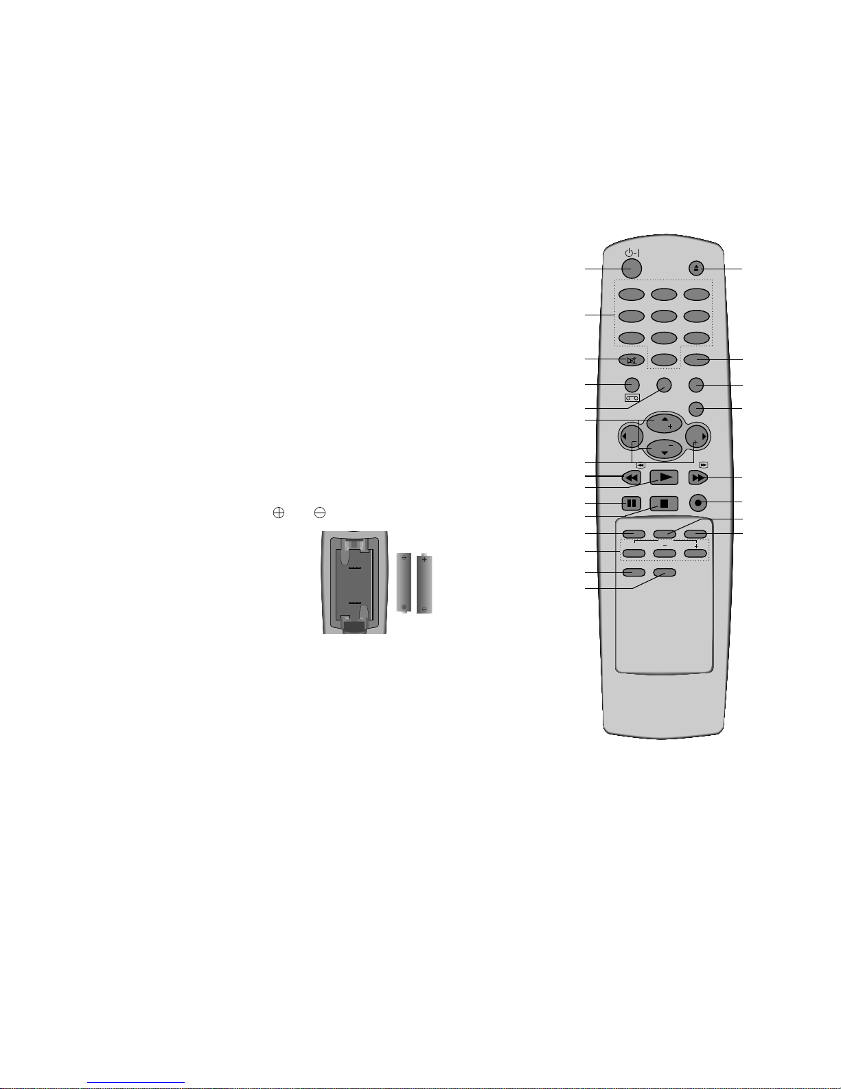
Remote control handset
Before you use the remote control handset, please install the
batteries. See the next page.
1. r-I (POWER)
switches the set on from standby or off to standby.
2. NUMBER BUTTONS
switch the set on from standby or directly select a number.
3. MUTE
switches the sound on or off.
4. TIMER PROG
displays the timer programme recording menu.
5. CLEAR/RESET
resets the tape counter or clears a data in the Timer
programme
menu.
6.
D
/
E
(PROGRAMME UP/DOWN)
switches the set on from standby.
selects a programme or a menu item.
7.
F/G
(VOLUME UP/DOWN)
adjusts the volume.
adjusts menu settings.
8. REW (REWIND/REVIEW)
rewinds the tape at high speed in the stop mode.
reviews fast the tape during playback.
9. PLAY
plays back the tape at normal speed.
10. PAUSE/STILL
stops the tape temporarily during recording.
displays a still picture during playback.
11. STOP
stops the tape during playback or recording.
12. SLEEP
sets the sleep timer.
13. TRK AUTO, +/-
adjust the picture automatically or manually during playback.
14. CLOCK/COUNT
displays the current time or tape counter.
15. SP/LP
selects a recording tape speed SP or LP.
16. TELETEXT BUTTONS (option)
These buttons are used for teletext.
For further details, see the ‘Teletext’ section.
OK
PR
VOL
PR
VOL
PLAY
P/STILL STOP
REC/ITR
REW/
FF/
SLEEP
AUTO
CLOCK/COUNT
TRK
SYSTEM Q.VIEW
SP/LP
?
TEXT
i
0
MUTE
TV/AV
MENU
CLEAR/RESETTIMER PROG
1
2 3
4
5 6
7
8 9
EJECT
1
3
4
5
6
7
8
12
13
15
16
10
2
9
11
14
(With TELETEXT)
17
18
19
21
23
22
24
20
1-7
Battery installation
The remote control handset is powered by two AA type batteries.
To load the batteries, turn the handset over and slide open the
battery compartment. Install two batteries as indicated by the
polarity symbols( and ) marked inside the compartment.
Note : To avoid damage from possible battery leakage, remove the
batteries if you do not plan to use the remote control handset for an
extended period of time.
17. EJECT
ejects the tape.
18. TV/AV
selects a TV or AV mode.
19. MENU
selects a menu.
20. OK
accepts your selection or displays the current mode.
21. FF (FAST FORWARD/CUE)
winds the tape forward at high speed in the stop mode.
fast forward playback.
22. REC/ITR
starts a manual recording or instant timer recording.
23. SYSTEM
selects the desired VCR colour system.
24. QUICK VIEW
returns to the previously viewed programme.
OK
PR
VOL
PR
VOL
PLAY
P/STILL STOP
REC/ITR
REW/
FF/
SLEEP
AUTO
CLOCK/COUNT
TRK
SYSTEM Q.VIEW
SP/LP
0
MUTE
TV/AV
MENU
CLEAR/RESETTIMER PROG
1
2 3
4
5 6
7
8 9
EJECT
1
3
4
5
6
7
8
12
13
10
2
9
11
14
15
(Without TELETEXT)
17
18
19
21
23
22
24
20

1-8
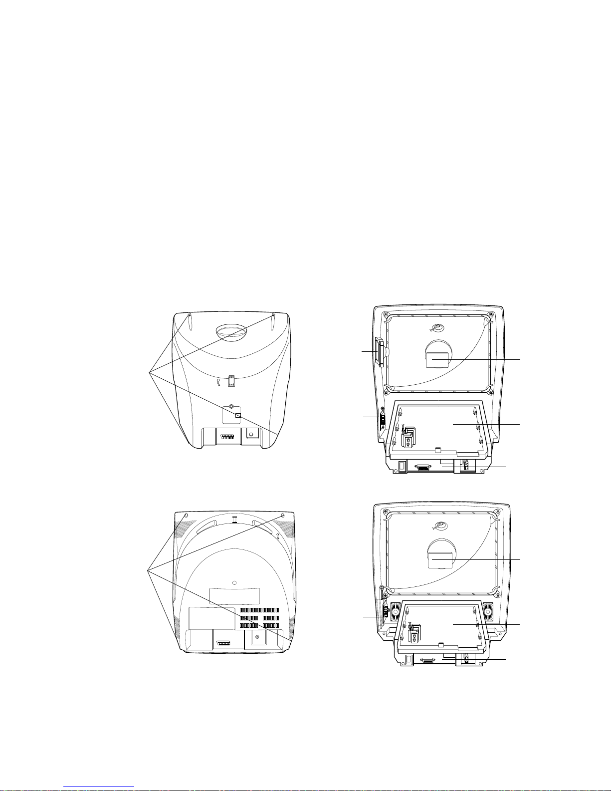
1. MAIN POWER (ON/OFF)
switches the set on or off.
Note : One power line lives even when the
main power is off.
2. POWER (r-I)
switches the set on from standby or off to
standby.
3. REMOTE CONTROL SENSOR
4. AUDIO/VIDEO IN SOCKETS (AV2)
Connect the audio/video out sockets of the
external VCR to these sockets.
5. REC/ITR
starts a manual recording or instant timer
recording.
6. PLAY
plays back the tape at normal speed.
7. PAUSE/STILL (option)
stops the tape temporarily during recording.
displays a still picture during playback.
8. MENU (option)
selects a menu.
9. STANDBY INDICATOR
illuminates red brightly when the set is in
standby mode.
dims red when the set is switched on.
10. TIMER REC INDICATOR
illuminates red when the timer programme is
set for recording.
11. VOLUME UP/DOWN
adjusts the volume.
adjusts menu settings.
12. PROGRAMME UP/DOWN
switches the set on from standby.
selects a programme or a menu item.
13. CASSETTE COMPARTMENT
To insert a video cassette tape here.
14. REC/ITR INDICATOR
illuminates red during recording.
15. REW (REWIND/REVIEW)
rewinds the tape at high speed in the stop
mode.
reviews fast the tape during playback.
16. FF (FAST FORWARD/CUE)
winds the tape forward at high speed in the
stop mode.
fast forward playback.
17. STOP/EJECT
stops the tape during playback or recording
or ejects the tape.
18. OK (option)
accepts your selection or displays the current
mode.
19. TAPE-IN INDICATOR (option)
illuminates green while a video cassette tape
is inserted.
20. HEADPHONE SOCKET (option)
connect the headphone plug to this socket.
Note : In some models, you might drop the set if
you move it only with the handle on the top of the
set. So you can should support the bottom of the
set at the same time.
Front panel
AV2
ON/OFF
VOL
PR
REC/ITR REW/ PLAY FF/ P/STILL STOP/EJECT MENU OK
VIDEO- IN -AUDIO
STAND-BY TAPE-IN TIMER REC
,,,,,,,,,,,,,,,,,
,,,,,
REC/iTR REW/
PLAY
FF/
P/STILL
STOP/EJECT
MENU
OK
VOL
PR
STAND-BY
TAPE-IN
TMER REC
ON/OFF
AV2
VIDEO- IN -AUDIO
20
20
4
14
13 15 16 17
1918
1
3 5 6 7 8
9
10 11
12
2 4
ON/OFF
/
VOL PR
STOP/EJECT REW/
PLAY FF/
REC/ITR
AV2
AUDIO
VIDEO
H/P
REC TIMER REC STAND-BY
IN
13 15 16
10 43
1
11
12
17 6 5
14
9
20
2
ON/OFF
VOL PR
STOP/EJECT REW/
PLAY FF/
REC/ITR
REC TIMER-REC STAND-BY
13 15 16
103
1
11
12
17 6 5
14
9 202
14
13 15 16 17
1918
1
3 5 6 7 8
9
10 11
12
2 4

CHASSIS : MV-995B
MODEL : KB/KE/KL/KF-14P2B/G/P/S
MODEL : KB/KE/KL/KF-14P2BX/GX/PX/SX
MODEL : KB/KE/KL/KF-20/21P30X
CONTENT
EXPLODED VIEW .............................................2-2
EXPLODED VIEW PARTS LIST..................2-3
DISASSEMBLY INSTRUCTIONS
..................2-6
SECTION 2 DISASSEMBLY PART
TVCR
SERVICE MANUAL

2-2
EXPLODED VIEW:14P2
330
340
320
315
300
120
501
520
310
943
400
603
610
601
602
121
A00
174
913
510
112
153
170
150

2-3
EXPLODED VIEW PARTS LIST
LOCA. NO PART NO DESCRIPTIONS
112 2055-00744L CPT SET A34KPU02XX 00N7ND
2055-00744K CPT SET A34KPU02XX 00L7ND * MOS-BWT
2055-00744M CPT SET A34KPU02XX 00P7ND * NAGHI
2055-00745J CPT SET A34KPU02XX 00S7ND * LGEAP
120 6400VA0019B SPEAKER,G9050402(C93H)8 OHM
121 4810V00205A BRACKET,SPK
150 150-D02B COIL,DEGAUSSING,CU 14” 42T 5.7 OHM
153 153-113V DY,DCAD2-14SNAB
170 170-A01E LEAD SET,CPT EARTH
300 3091V00251G CABINET ASSY(BLUE)
3091V00251C CABINET ASSY(GREEN)
3091V00251F CABINET ASSY(SILVER)
3091V00251H CABINET ASSY(PINK)
310 5020V00382A BUTTON,CONTROL
315 3580V00014J DOOR,CST(BLUE)
3580V00014K DOOR,CST(PINK)
3580V00014T DOOR,CST(SILVER)
3580V00014W DOOR,CST(GREEN)
320 320-075B SPRING,KNOB
330 5020V00381A BUTTON,POWER
340 5020V00383A BUTTON,CONTROL
400 3809V00185B BACK COVER ASSY(GREEN)
3809V00185C BACK COVER ASSY(BLUE,SCART)
3809V00185E BACK COVER ASSY(SILVER,SCART)
3809V00185F BACK COVER ASSY(BLUE,PHONO)
3809V00185D BACK COVER ASSY(PINK,SCART)
3809V00185G BACK COVER ASSY(PINK,PHONO)
501 4810V00012A BRACKET,SMPS
520 6871VDM105A PWB ASSY,MAIN2 14”,NARROW
601 4810V00195C BRACKET,MAIN
602 4814V00158B SHIELD,BOTTOM
603 4814V00157E SHIELD,TOP CASE
610 6871VMM449A PWB ASSY,MAIN KE,E/D/F,W/TXT,SCART
6871VMM449B PWB ASSY,MAIN KE,E/D/F,W/O TXT,SCART
6871VMM449C PWB ASSY,MAIN KL,E/D/F,W/O TXT,SCART
6871VMM449D PWB ASSY,MAIN KE,E/I/S,W/TXT,SCART
6871VMM449H PWB ASSY,MAIN KF,E/RUS,W/O TXT,PHONO
6871VMM449M PWB ASSY,MAIN KB,E/D/F,W/O TXT,PHONO
913 332-057A SCREW ASSY,HEXAGON HEAD
943 1PTF0403116 SCREW,TAP TITE D4.0 L16.0
A00 6721R-0105B DECK ASSY,D33(TV-33A2OMO 1KT2,2HD,NP
P801 174-009V CORD,POWER(W/HOLD,HOUSING)L=400,4.0
174-224G CORD,POWER H03VVH2-F
174-222W CORD,POWER
The components identified by mark is
critical for safety.
Replace only with part number specified.

330
320
315
603
610
601
602
A00
501
520
P801
913
510
112
153
170
150
310
943
400
120
EXPLODED VIEW:20/21P30X
2-4
2-5
112 2055-01221L - CPT
2055-01221K 2424GDA80AV CPT *MOS-BWT
2055-01221S 2424GDA80AB CPT *LGESW ,A.E.C,LGEGF
2055-01221Q 2426GDA80AG CPT *LGEAP
120 120-D44D 120-D44D SPEAKER,16OHM 3W/5
150 150-D02M 150-D02M COIL,DEGAUSSING
153 153-276A 6150Z-1023A DY
170 170-A01F 170-A01F LEAD SET,CPT EARTH
300 3091V00268C - CABINET ASSY(W/O SECAM)
3091V00268D 3091V00269D CABINET ASSY(W/SECAM)
310 5020V00401B 5020V00399A BUTTON,CONTROL
315 3580V00014Y - DOOR,CST,W/O SECAM
3580V00014S 3580V00014S DOOR,CST,W/SECAM
330 5020V00402A 5020V00400A BUTTON,POWER
400 3809V00195C 3809V00195C BACK COVER ASSY
501 4810V00206B 4810V00206B BRACKET,SMPS
520 6871VDM105B 6871VDM105C PWB ASSY,MAIN2 CKD ,NARROW
6871VDM105E 6871VDM105F PWB ASSY,MAIN2 CKD KF-
6871VDM105L 6871VDM105M PWB ASSY,MAIN2 CKD KB-
601 4810V00195A 4810V00195A BRACKET,MAIN
602 4814V00158B 4814V00158B SHIELD,BOTTOM
603 4814V00157F 4814V00157F SHIELD,TOP CASE
610 6871VMM449A - PWB ASSY,MAIN PAL E/D/F,W/TXT
6871VMM449B 6871VMM449B PWB ASSY,MAIN PAL E/D/F,W/O TXT
6871VMM449C 6871VMM449C PWB ASSY,MAIN PAL E/D/F,W/O TXT
6871VMM449F - PWB ASSY,MAIN PAL E/D/F,W/TXT
6871VMM449H 6871VMM449H PWB ASSY,MAIN PAL E/RUS,W/O TXT
6871VMM449K 6871VMM449K PWB ASSY,MAIN KF E/D/F,W/O TXT
6871VMM449L 6871VMM449L PWB ASSY,MAIN KF E/D/F,W/TXT
913 332-057B 332-057B SCREW ASSY,HEXAGON HEAD
943 1PTF0403116 1PTF0403116 SCREW,TAP TITE D4 L16
P801 174-224G 174-224G POWER CORD
174-009Q 174-009Q POWER CORD
174-222W 174-222W POWER CORD
LOCA. NO
20” 21”
PART NO
DESCRIPTIONS
EXPLODED VIEW PARTS LIST
The components identified by mark is
critical for safety.
Replace only with part number specified.
DISASSEMBLY INSTRUCTIONS
2-6
1. Back Cover Removal
Remove th
sepa
hol
2. Main 2 PCB Removal
Gra
3. Main Chassis Removal
1)
c
2)G
4. Speaker Assembly Removal
1)
c
2)
5. CPT REMOVAL
1
C
2)P
3
4)
PICTURE TUBE HANDLING CAUTION
Due to
c
p
TH
or s
result
pers
Fig. 2-1
Fig. 2-2
CPT
Board
Remove
Screws
Remove
Screws
Main 2
PCB
Side AV
PCB
Main chassis
CPT
Board
Main 2
PCB
Side AV
PCB
Main chassis
Speaker
MODEL:14P2
MODEL:20/21P30X

CHASSIS : MV-995B
MODEL : KB/KE/KL/KF-14P2B/G/P/S
MODEL : KB/KE/KL/KF-14P2BX/GX/PX/SX
MODEL : KB/KE/KL/KF-20/21P30X
CONTENT
PURITY & CONVERGENCE ADJUSTMENT
........3-2
ADJUSTMENT INSTRUCTIONS .................3-5
BLOCK DIAGRAM ..............................................3-7
WIRING DIAGRAM ........................................ 3-10
TROUBLESHOOTING CHARTS .................3-11
COMPONENT LOCATION GUIDE.............3-16
PRINTED CIRCUIT BOARDS .......................3-17
SECTION 3 ELECTRICAL PART
TVCR
SERVICE MANUAL

3-2
PURITY & CONVERGENCE ADJUSTMENT
Caution:
Convergence and Purity have been factory aligned. Do not
attempt to tamper with these alignments.
However, the effects of adjacent receiver components, or
replacement of picture tube or deflection yoke may require the
need to readjust purity any convergence.
¡ Purity Adjustment
This procedure DOES NOT apply to bonded yoke and picture
tube assemblies.
The instrument should be at room temperature (60 degrees F or
above) for six (6) hours and be operating at low beam current
(dark background) for approximately 20 to 30 minutes before
performing purity adjustments.
CAUTION: Do not remove any trim magnets that may be
attached to the bell of the picture tube.
1. Remove the AC power and disconnect the internal
degaussing coil.
2. Remove the yoke from the neck of the picture tube.
3. If the yoke has the tape version beam bender, remove it and
replace it with a adjustable type beam bender (follow the
instructions provided with the new beam bender)
4. Replace the yoke on the picture tube neck, temporarily
remove the three (3) rubber wedges from the bell of the
picture tube and then slide the yoke completely forward.
5. Reconnect the internal degaussing coil.
6. Position the beam bender locking rings at the 9 o'clock
position and the other three pairs of tabs (2,4 and 6 pole
magnets) at the 12 o'clock position.
7. Perform the following steps, in the order given, to prepare the
receiver for the purity adjustment procedure.
a. Face the receiver in the "magnetic north" direction.
b. Externally degauss the receiver screen with the television
power turned off.
c. Turn the television on for approximately 10 seconds to
perform internal degaussing and then turn the TV off.
d. Unplug the internal degaussing coil. This allows the
thermistor to cool down while you are performing the purity
adjustment. DO NOT MOVE THE RECEIVER FROM ITS
"MAGNETIC NORTH" POSITION.
e. Turn the receiver on and obtain a red raster by increasing
the red bias control (CW) and decreasing the bias controls
for the remaining two colors (CCW).
f. Attach two round magnets on the picture tube screen at 3
o'clock and 9 o'clock positions, approximately one (1) inch
from the edge of the mask (use double-sided tape).
DEFLECTION YOKE
PURITY &CONVERGENCE
MAGNET ASSEMBLY
RUBBER
WEDGES
GLASS CLOTH TAPE
PURITY MAGNET
6-POLE
4-POLE
4-POLE
MAGNET
CONVERGENCE MAGNET ASSEMBLY
6-POLE
MAGNES
PURITY MAGNET(2-POLE)
X-AXIS YOKE
POSITIONING
(L/R PURITY)
6-POLE
MAGNETS
CONVERGENCE MAGNET ASSEMBLY
3-3
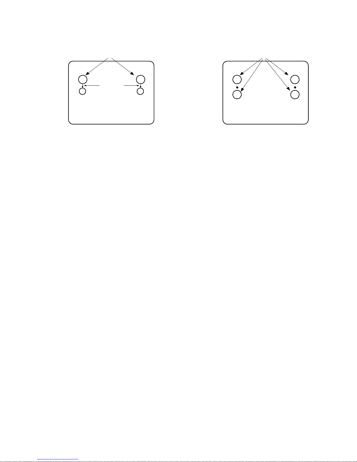
8. Referring to above, perform the following two steps:
a. Adjust the yoke Z-axis to obtain equal blue circles.
b. Adjust the appropriate beam bender tabs to obtain correct
purity (four equal circles).
9. After correct purity is set, tighten the yoke clamp screw and
remove the two screen magnets.
10. Remove the AC power and rotate the receiver 180 degrees
(facing "magnetic south").
11. Reconnect the internal degaussing coil.
12. Turn the receiver on for 10 seconds (make sure the receiver
came on) to perform internal degaussing, and then turn the
receiver off.
13. Unplug the internal degaussing coil.
14. Turn on the receiver and check the purity by holding one (1)
round magnet at the 3 o'clock and a second round magnet at
9 o'clock position. If purity is not satisfactory, repeat steps 8
through 14.
15. Turn off the receiver and reconnect the internal degaussing
coil.
¡ Convergence Adjustment
Caution: This procedure DOES NOT apply to bonded yoke and
picture tube assemblies.
Do not use screen magnets during this adjustment
procedure. Use of screen magnets will cause an
incorrect display.
1. Remove AC power and disconnect the internal degaussing
coil.
2. Apply AC Power and set the brightness to the Picture Reset
condition. Set the Color control to minimum.
3. Apply 8V to the pin.
4. Adjust the Red, Green and Blue Bias controls to get a dim
white line.
5. Remove the AC power and 8V from the pin.
6. Reconnect the internal degaussing coil and apply AC power.
7. Turn the receiver on for 10 seconds to perform internal
degaussing and then turn the receiver off again.
8. Unplug the internal degaussing-coil.
9. Turn on the receiver, connect a signal generator to the VHF
antenna terminal and apply a crosshatch signal.
Caution: During the convergence adjustment procedure, be
very careful not to disturb the purity adjustment tabs
are accidentally move, purity should be confirmed
before proceeding with the convergence adjustments.
Note:
Make sure the focus is set correctly on this instrument
before proceeding with the following adjustment.
10. Converge the red and blue vertical lines to the green vertical
line at the center of the screen by performing the following
steps (below TABLE).
a. Carefully rotate both tabs of the 4-pole ring magnet
simultaneously in opposite directions from the 12 o'clock
position to converge the red and blue vertical lines.
b. Carefully rotate both tabs of the 6-pole ring magnet
simultaneously in opposite directions form the 12 o'clock
position to converge the red and blue (now purple)
vertical lines with the green vertical line.
11. Converge the red and blue horizontal with the green line at
the center of the screen by performing the following steps.
(below TABLE)
a. Carefully rotate both tabs of the 4-pole ring magnet
simultaneously in the same direction (keep the spacing
between the two tabs the same) to converge the red and
blue horizontal lines.
b. Carefully rotate both tabs of the 6-pole ring magnet
simultaneously in same direction (keep the spacing
between the two tabs the same) to converge the red and
blue (now purple) horizontal lines with the green
horizontal line.
c. Secure the tabs previsouly adjusted by locking them in
place with the locking tabs on the beam bender.
MAGNETS
RED RED
1.ADJUST YOKE Z-AXIS FIRST
TO GET EQUAL BLUE
COLOR CIRCLES
2 .ADJUST BEAM BENDER 2 POLE
MAGNET TO GET FOUR EQUAL
COLOR CIRCLES

3-4
RING
PAIRS
4
POLE
ROTATION DIRECTION
OF BOTH TABS
OPPOSITE
SAME
OPPOSITE
SAME
MOVEMENT OF RED
AND BLUE BEAMS
B B
RR
OR
OR
B R B R
OR
B
R
B
R
B R
OR
B
R
6
POLE
12. While watching the 6 o'clock positions on the screen, rock the
front of the yoke in a vertical (up/down) direction to converge
the red and blue vertical lines. (Fig upper left)
13. Temporarily place a rubber wedge at the 12 o'clock position
to hold the vertical position or the yoke.
14.
Check the 3 o'clock and 9 o'clock areas to confirm that the red
and blue horizontal lines are converged.
If the lines are not converged, slightly offset the vertical tilt of the
yoke (move the rubber wedge if necessary) to equally balance the
convergence error of the horizontal lines at 3 o'clock and 9 o'clock
and the vertical lines at 6 o'clock and 12 o'clock.
15. Place a 1.5 inch piece of glass tape over the rubber foot at
the rear of the 12 o'clock wedge.
16. While watching the 6 o'clock and 12 o'clock areas of the
screen, rock the front of the yoke in the horizontal (left to
right) motion to converge the red and blue horizontal lines.
(Fig. upper right)
17. Temporarily place a rubber wedge at the 5 o'clock and 7
o'clock positions to hold the horizontal position of the yoke.
18. Check the 3 o'clock and 9 o'clock areas to confirm that the
red and blue vertical lines are converged. If the lines are not
converged, slightly offset the horizontal tilt of the yoke (move
the temporary rubber wedges if necessary) to equally
balance the convergence error of the horizontal lines at 6
o'clock and 12 o'clock and the vertical lines at 3 o'clock and 9
o'clock.
19. Using a round magnet confirm purity at the center, right and
left sides and corners. See Purity Adjustment Procedure.
20. Reconfirm convergence and apply a 1.5 inch piece of glass
tape over the rubber foot at the rear of the 5 o'clock and the 7
o'clock wedges.
RED
BLUE
RED BLUE
BLUE
RED
GREEN
GREEN
BLUE RED
GREEN
GREEN
ADJUSTMENT
VIEWING
AREA
UP/DOWN ROCKING OF THE YOKE
CAUSES OPPOSITE ROTATION OF RED
AND BLUE RASTERS
ADJUSTMENT
VIEWING
AREA
RED
RED
GREEN
TV
SCREEN
LEET/RIGHT ROCKING OF THE YOKE
CAUSES OPPOSITE SIZE CHANGE OF
THE RED AND BLUE RASTERS
UP/DOWN ROCKING OF THE YOKE
CAUSES OPPOSITE ROTATION OF RED
AND BLUE RASTERS
LEFT/RIGHT ROCKING OF THE YOKE
CAUSES OPPOSITE SIZE CHANGE OF THE
RED AND BLUE RASTERS
3-5
ADJUSTMENT INSTRUCTIONS
Notes;
(Ad
1.
when s
d
2. T
5
3.
op
1. DECK ADJUSTMENT
1. Deck Transit System Adjustment
1-1. Necessary Instruments
1
2)
3
4)
(P2,
5)
1-2.Preliminary Steps
1)
PCB. Trigger on this channel.
2)C
PCB.
3
4)Wh
TRK
tra
5)
step
1-3. RF linearity check and adjustment
1)
m
2)C
by p
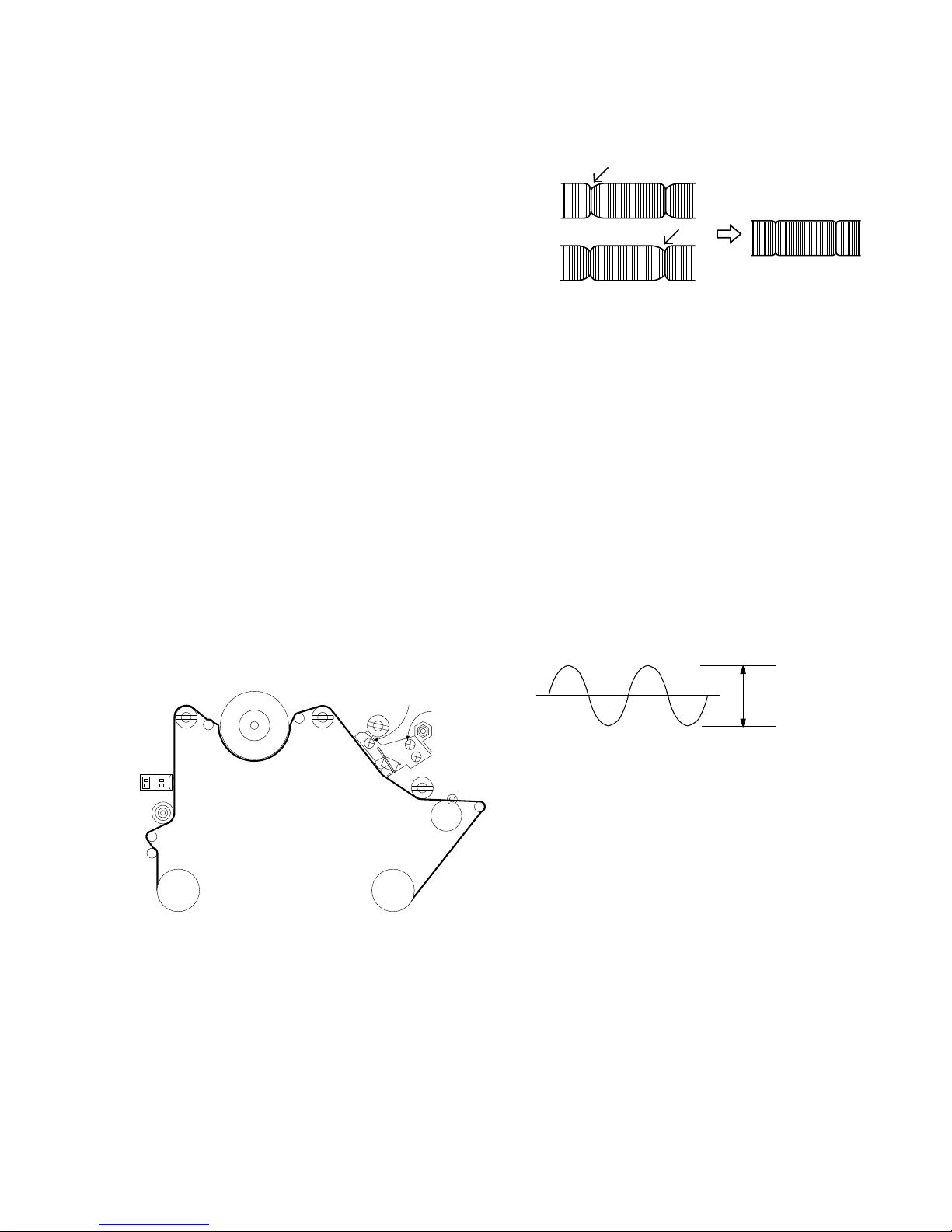
1-4. X-Distance Adjustment
1
RF
2)C
pre
CAUTION: I
the
(
1-5. Audio Level Check and Adjustment
1
to J
res
2)P
an
the
3
6
2. CIRCUIT ADJUSTMENT
1. PG Adjustment
1-1. Necessary Instruments
1
2)
3
1-2.Adjustment
1
2)C
M
O
3
the
4)
b
DRUM
P2
FE HEAD
P1
ARM
TENSION
P0
SUPPLY
REEL
TAKE-UP
REEL
PINCH
ROLLER
TAPE
CAPSTAN
T/UP
ARM
P4
A/C
HEAD
P3
X-DISTANCE
ADJUST SCREW
AZIMUTH
SCREW
CONE POINT
SCREW
A/C HEAD
HEIGHT ADJUST NUT
<A
P2 POST ADJUST
P2
P3
P3 POST ADJUST
<
Adjust waveform
<

3-6
3. Focus Voltage Adjustment
1)
2)Pres
c
3)
4. Screen Adjustment
1)
2)
3)
4)A
¡
HHooww ttoo ggeett iinnttoo SSVVCC mmooddee wwhheenn yyoouu ddoonn''tt hhaavvee SSVVCC
RReemmoottee CCoonnttrroolllleerr..
PPuusshh tthhee ""OOKK"" KKeeyy oonn tthhee uusseerr''ss RReemmoottee CCoonnttrroolllleerr aanndd llooccaall
""OOKK"" bbuuttttoonn aatt tthhee ssaammee ttiimmee..
5. SIF Adjustment
1)
2)
3)
6. RF AGC Adjustment
1)
2)C
3)
into SV
4)
b
7. White Balance Adjustment
1
wh
2)
3
i
4)
Press
¡ G
8 Deflection Data Adjustment
1
2)Pr
se
3
4)
5) Vertical SLOPE adjustment
¤ Sel
¤Ł Pre
the
6) Vertical amplitude adjustment
¤ Sel
¤Ł Pre
l
of
7) Vertical Shift Adjustment
¤ Sel
¤Ł Pre
wit
8) Horizontal Shift Adjustment
¤ Sel
¤Ł Pre
wit
9) Vertical S-Correction Adjustment
¤ Sel
¤Ł Pres
Pattern
Adjust Period
<Adjust Waveform>
* CAUTION:
MODEL
Electric fields strength
AGC Voltage
65dBu
¡ 0.2dBu
2.3
¡ 0.1Vdc
65dBu
¡ 0.2dBu
2.1¡ 0.1Vdc
KL/KF/KE KI
V
140V
GND
Black Level (DC)

3-7
BLOCK DIAGRAM

VCD BLOCK DIAGRAM
3-8

VIDEO/AUDIO BLOCK DIAGRAM
3-9

3-10
WIRING DIAGRAM
TOUCH .
P805
P805
1
P708
1
P602
P804
P03
P01
P02
P708
P602
P805
P804
P708
P102
P702
P703
P901A
SMPS PWB
P802
P103
P100
CPT PWB
 Loading...