

Page 1
AIR
CONDITIONER
Please read this manual carefully before operating
your set and retain it for future reference.
TYPE : LO-STATIC CEILING DUCT TYPE AIR CONDITIONER
For Single LO-Static duct models
MFL62760204
P/No. : MFL62760204_v1
CUSTOMER CARE
1800-180-3575 (Toll Free)
CALL
Regd. Office : LG Electronics India Pvt. Ltd., A Wing (3rd Floor), D-3, District Center, Saket, New Delhi - 110017
12 x 7
(9:00 AM – 9:00 PM)
www.lg.com/in/support
CLICK
cac.service@lgepartner.com
To know more about LG, visit www.lg.com
For Corporate/Instutional enquiries,
please write to enquiries@lgindia.com
Page 2
Low Static Hide Away Type Air Conditioner Owner's Manual
TABLE OF CONTENTS
F or Your Records
Write the model and serial numbers here:
Page no.
1. Safety Precautions
2. Operating Instructions
3. Care and Maintenance
4.
Before you call for service
14
19
Model #
Serial #
3
You can find them on a label on the side of each unit.
5
Dealer's Name
Date Purchased
R
ead This Manual
Inside you will find many helpful hints on how to use
and maintain your air conditioner properly. Just a little
preventive care on your part can save you a great
deal of time and money over the life of your air
conditioner.
You'll find many answers to common problems in the
chart of troubleshooting tips. If you review our chart of
Troubleshooting Tips first, you may not need to call
for service at all.
CAUTION
• Contact the authorized service technician for repair
or maintenance of this unit.
• Contact the installer for installation of this unit.
• The air conditioner is not intended for use by young
children or invalids without supervision.
• Young children should be supervised to ensure that
they do not play with the air conditioner.
• When the power cord is to be replaced, replacement
work shall be performed by authorized personnel
only.
• Installation work must be performed in accordance
with the nati onal wiring standard s by au thorized
personnel only.
2
Page 3
Safety
Precautions
To prevent injury and property damage, follow these instructions.
Incorrect operation due to ignoring instructions will cause harm or damage, the seriousness of which is
indicated by the following symbols.
Precautions
WARNING
CAUTION
This symbol shows the possibility of death or serious injury.
This symbol indicates the possibility of injury or damage to property.
Never Do This
Always Do This
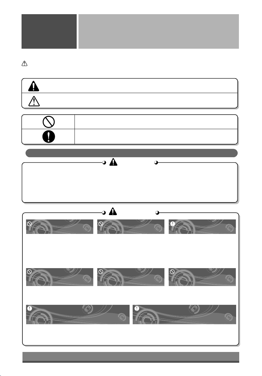
Installation precautions
WARNING
WARNING
n
Do not install, remove and reinstall the unit by yourself.
• Improper installation will cause water leakage, electrical shock, or fire. Please consult
authorized dealer or specialist for the installation work. Please note fault caused by improper
installation is not covered by warranty.
• Unit must be installed in an easily accessible area. Any additional cost required to hire a
special equipment to service the unit will be the responsibility of the customer.
WARNING
WARNING
Do not damage or use an
unspecified power cord.
•
It will cause electrical shock or fire.
• If the supply cord is damaged, it must be
replaced by the manufacturer or its
service agent or a similarly qualified
person in order to avoid a hazard.
Do not operate or stop the
unit by inserting or pulling
out the power plug.
• It will cause electrical shock or
fire due to heat generation.
When an abnormality (smell of burning, etc)
occurs, stop the air conditioner, and
turn off the breaker.
• If the unit continues to be operated in an abnormal
condition, it may cause a fire, trouble, etc. In this
case, consult your dealer.
Do not operate switches
with wet hands.
• It may cause electrical shock.
Do not insert your finger or
stick, etc. into the air inlet/air
outlet.
• Since the fan rotates at high
speed, this may cause an injury
or damage the unit.
Repair or relocation should not be done by the
customer.
• If this is done in correctly, it may cause a fire,
electric shock, injury by dropping of the unit, water
leakage, etc. Consult your dealer.
Plug in the power plug
properly.
• Otherwise, it will cause
electrical shock or fire due to
heat generation.
Do not expose the skin to
cool air directly for a long
time.
• This could damage your health.
3
Page 4
CAUTION
CAUTION
• Contact the authorized Service technician for repair or maintenance of this unit.
• Contact the installer for installation of this unit.
• The air conditioner is not intended for use by young children or infirm persons without
supervision.
• Young children should be supervised to ensure that they do not play with the air conditioner.
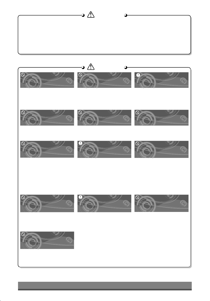
CAUTION
CAUTION
Do not clean the air
conditioner with water.
l Water may enter the unit and
degrade the insulation. It may
cause an electric shock.
Ventilate well when used
together with a stove, etc.
l An oxygen shortage may occur.
When the unit is to be
cleaned, switch off, and turn
off the breaker.
l Since the fan rotates at high
speed during operation, it may
cause an injury.
Do not put a stove, etc.
where is exposed to direct
air flow.
l It may cause imperfect
combustion.
Do not operate for a long
time in high humidity, e.g.
leaving a door or window
open.
l In the cooling mode, if it is
operated in a room with high
humidity (80%r.h. or more) for a
long time, water condensed in
the air conditioner may drop and
may wet and spoil furniture, etc.
If the supply cord is damaged, it
must be replaced by a special cord
or assembly available from the
manufacturer of its service agent.
l If will cause electrical shock or
fire.
Do not touch or pull the lead
wire with wet hands.
lIt will cause product breakdown
or electric shock.
When the unit is not going to
be used for a long time, turn
off the breaker.
l It may cause an injury.
Do not step onto an unstable
bench when
attaching/detaching the
panel.
l It may case an injury, etc. by
falling down.
When the air filter is to be
removed, do not touch the
metal parts of the indoor unit.
l It may cause an injury.
Do not step on the outdoor
unit and do not put anything
on it.
l It may cause an injury through
dropping or falling down.
Do not use for special
purposes.
l Do not use this air conditioner to
preserve precision devices, food,
animal, plants and art objects.
It may cause deterioration of
quality, etc.
Do not press the screen
using powerful pressure
or select two buttons.
lIt will cause product breakdown
or malfunction.
4
Page 5
2. Operating Instructions
A) Indoor Unit, Outdoor Unit
Wired Remote
Controller (Optional)
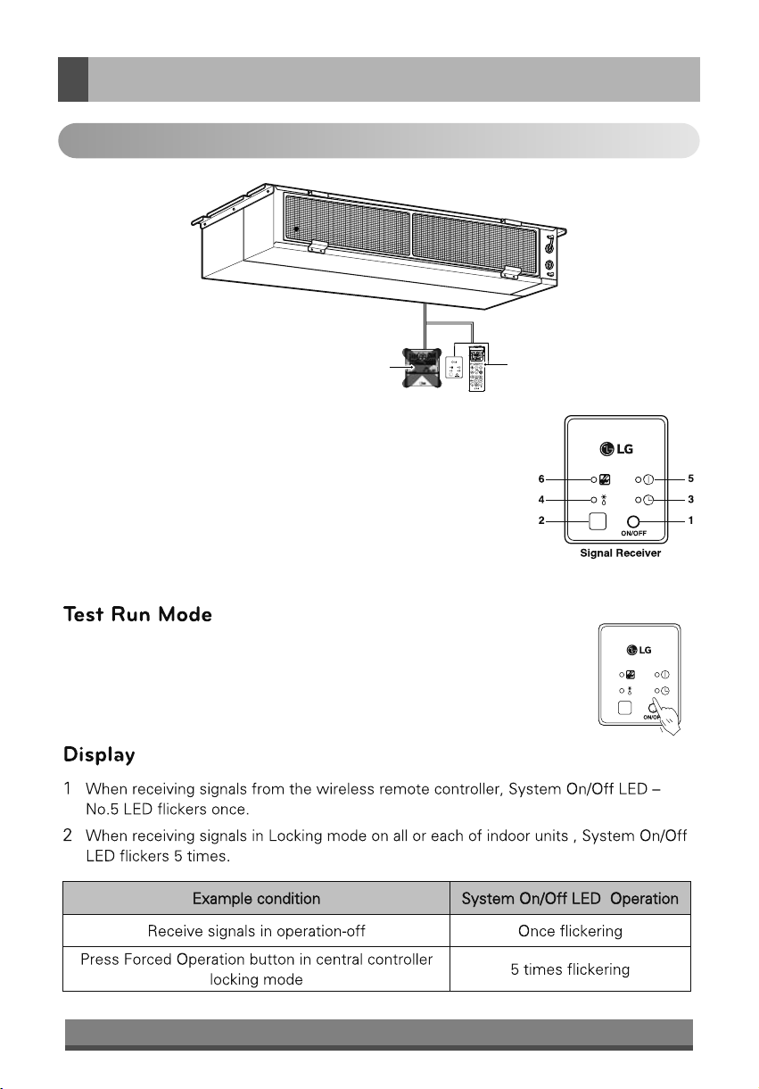
Wireless Remote Receiver & Controller
(Standard)
Operation of Indication Lamps
1 Emergency Operation button :Turns the indoor unit on or off even when
remote control is not working.
2 Signal Detector : Receives the signal from remote control
3 Timer lamp (Green) : Lights up during the timer operation.
4 Hotstart lamp (Orange) : Available only for the heat pump models, not
cooling only models.
5 System On/Off lamp (Red) : Lights up during system controller operation.
6 Filter Sign lamp (Green) : Lights up after 2,400 hours from the time of
first power on operation.
After installing the product, you must run a Test Run mode. Press
the Emergency Operation button for 5 seconds, until the LED
flickers. Then the indoor unit, duct runs cooling mode for 18
minutes, where the d esir ed tem pera ture i s 18 °C and the
Wind strength is high.
5
Page 6
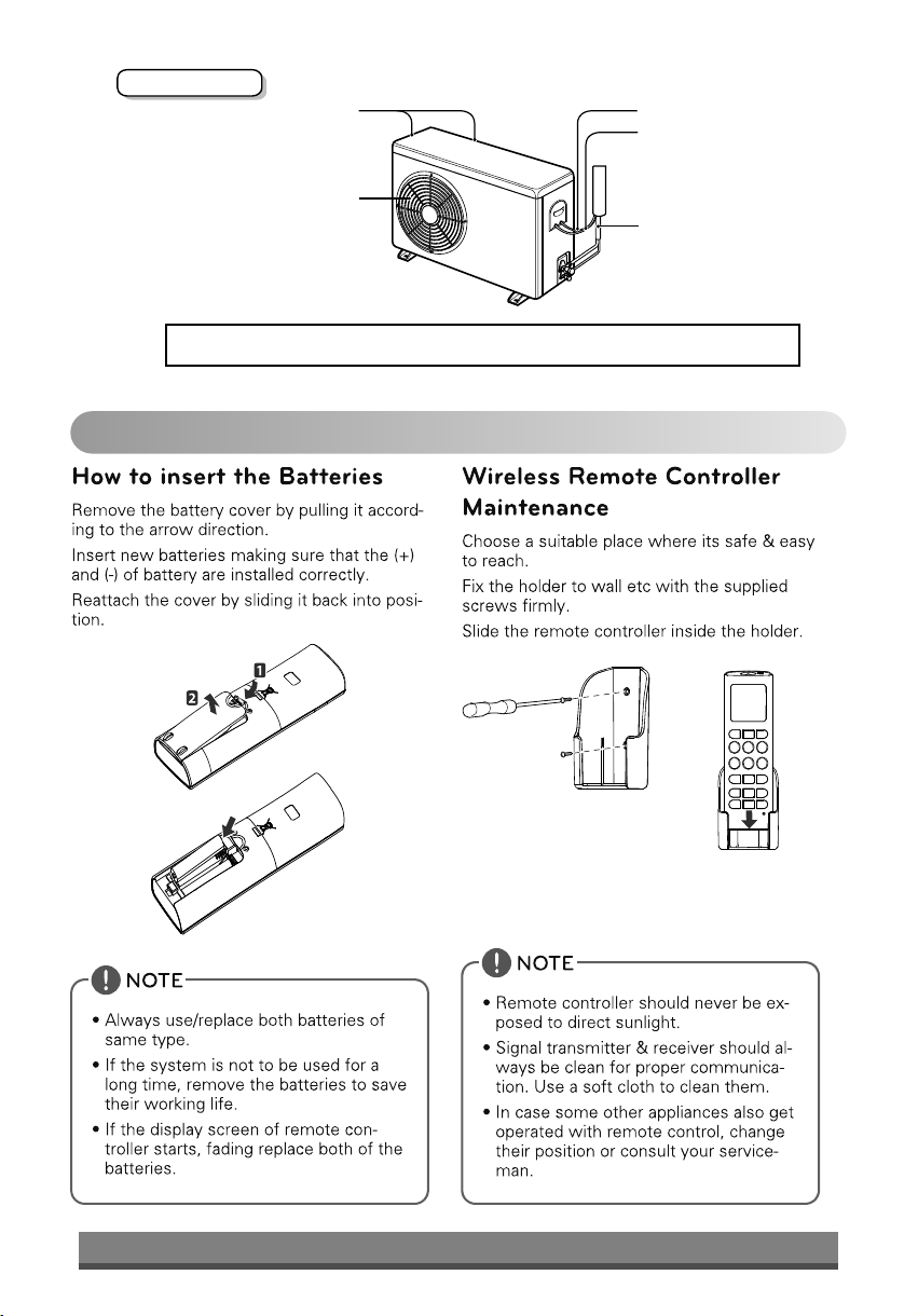
Outdoor Unit
Air Intake
(side, rear)
Air Outlet
Vents
Cooling model: Low static Type Air Conditioner for cooling
B) Remote Control Preparation
Connecting Wire
Power Wire
Connection Tube
6
Page 7
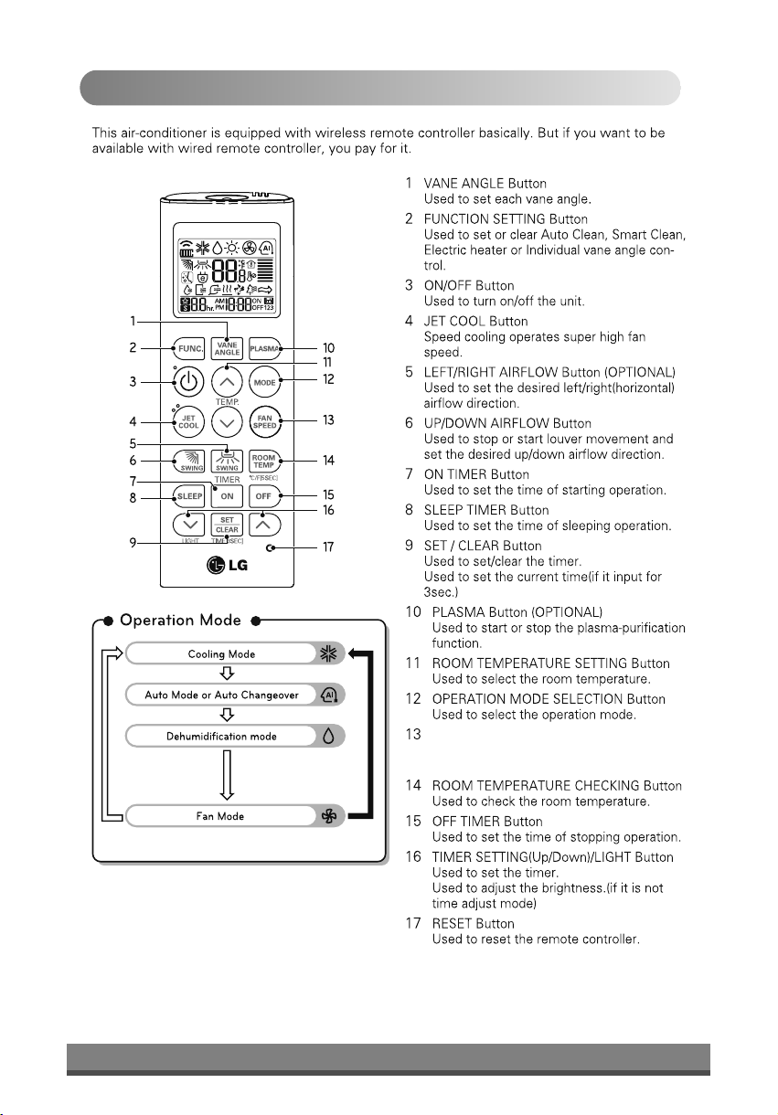
C) Remote Control Operations
*
*
*
*
*
* Function not applicable for Lo-Static Duct Model.
7
INDOOR FAN SPEED SELECTION Button
Used to select fan speed in three steps low,
medium and high.
Page 8
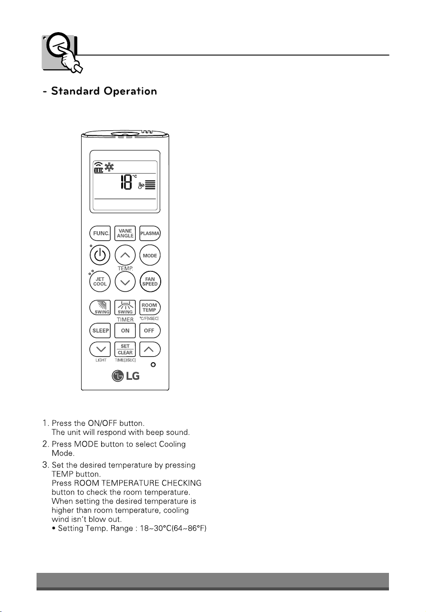
Cooling Mode
8
Page 9
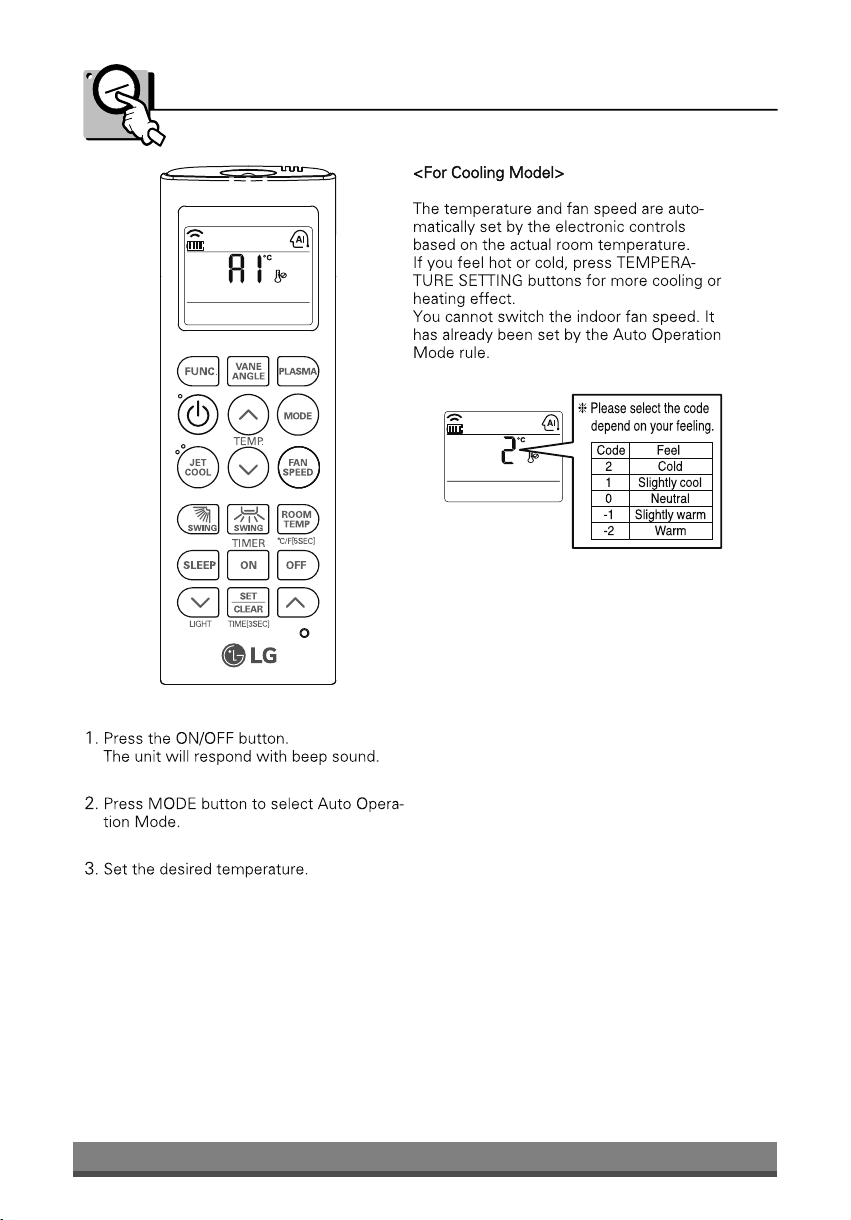
Auto Operation Mode
9
Page 10
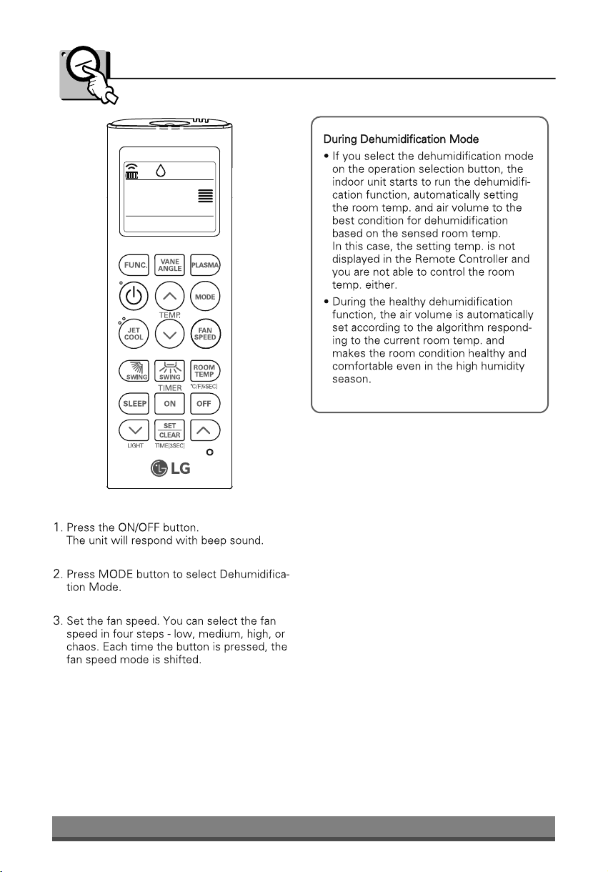
Dehumidification Mode
10
Page 11
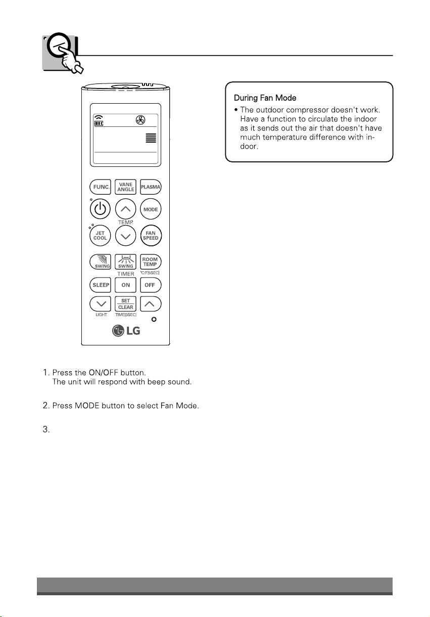
Fan Mode
Set the fan speed again. You can select the
fan speed in three steps – low, medium and high.
Each time the button is pressed, the fan
speed mode is shifted.
11
Page 12
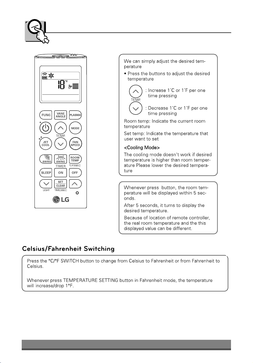
Temperature Setting/Room Temperature Checking
12
Page 13

Timer
13
Page 14
Care and
maintenance
Caution: Before performing any maintenance, turn off the main power to the system.
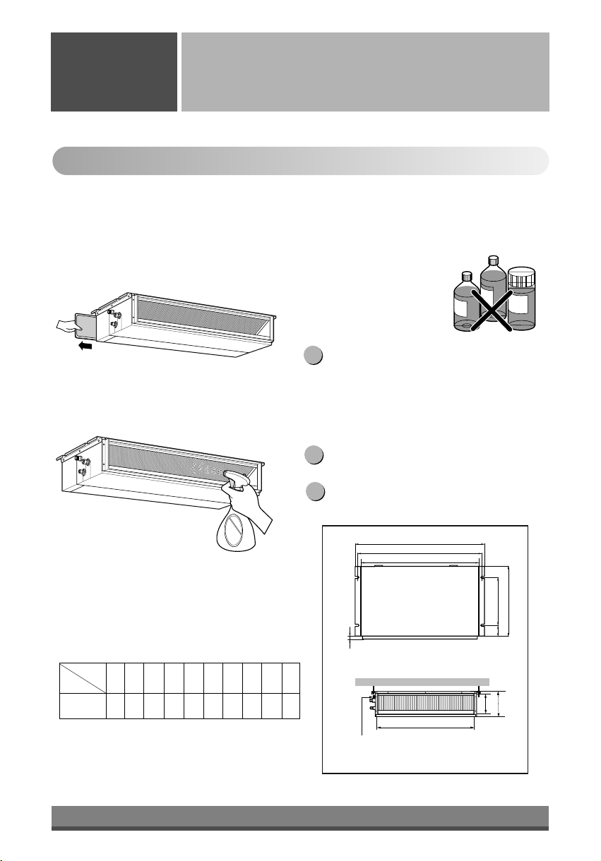
Care and maintenance
Indoor Unit
Never use any of the followings:
Grille, Case, and Remote Control
q Turn the system off before cleaning. To clean,
wipe with a soft, dry cloth. Do not use bleach or
abrasives.
Note:
Supply power must be disconnected before
cleaning the indoor unit.
Air Filter
The air filters behind Indoor unit
(the suction side) should be checked and cleaned
once every 2 weeks or more often if necessary.
q
• Water hotter than 40°C
Could cause deformation and/or
discoloration.
• Volatile substances
Could damage the surfaces
of the air conditioner.
Clean the filter with a vacuum or warm, soapy
1
water.
• If very dirty, wash with a solution of
detergent in lukewarm water.
• If hot water (50°C or more) is used, filter
may be deformed.
After washing with water, dry well in the shade.
2
S
I
N
N
E
R
S
C
O
G
U
N
I
R
B
e
n
e
z
n
e
C
L
B
A
R
E
R
G
Indoor Unit Dimensions (mm)
Dimension
Capacity(Btu/h)
18/24/ Btu/h
A B C D E F G H I J
1130 1180 383 575 93 190 21 1065 163 1100
(Unit:mm)
Re-install the air filter.
3
Drainage hole
14
B
A
J
D
CE
G
I
F
H
Drain Pump use
Page 15
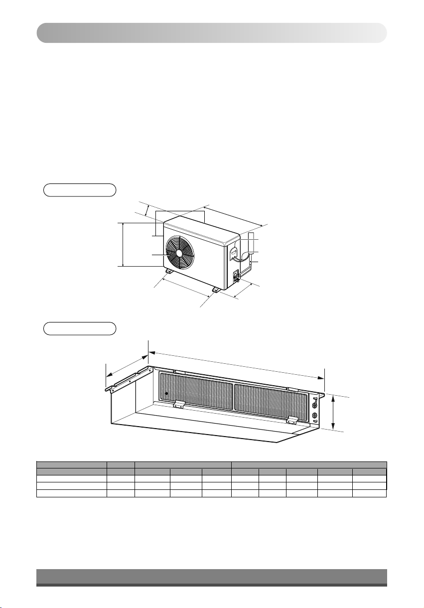
Outdoor Unit
The heat exchanger coils and panel vents of the
outdoor unit should be checked regularly. If clogged
with dirt or soot, the heat exchanger and panel vents
may be professionally steam cleaned.
Note:
Dirty or clogged coils will reduce the operating
efficiency of the system and cause higher
operating costs.
Outdoor Unit
Outdoor Unit
H
D
(Side)
Air intake
vents
Air outlet
vents
L1
(Rear)
W
Control Cover
Connecting Wir
Connection Pip
L2
e
e
Indoor Unit
D
Model Capacity Indoor dimension Outdoor Dimension
JB-Q18GB2A0
JB-Q24GB2A0
JB-Q18GB2A1
1.5TR
2.0TR
1.5TR
W D H W D H L1 L2
1180 575 190 800 260 555 590 305
1180 575 190 800 260 555 590 305
1180
575
W
190 770 288
H
545 560 330
15
Page 16

When the air conditioner is not going to be used for a long time.
When it is not going to be used for
Operate the air conditioner on Air circulation
1
mode (Refer to page 15) for 2 to 3 hours.
• This will dry out the internal parts.
Turn off the circuit breaker.
2
Turn off the circuit breaker when the air conditioner
is not going to be used for a long time.
Dirt may collect and may cause a fire.
a long time.
CAUTION
CAUTION
Operation Tips
Do not overcool the room.
This is not good for the health
and wastes electricity.
Keep blinds or curtains
closed.
Do not let direct sunshine
enter the room when the air
conditioner is in operation.
When the air conditioner is to
be used again.
n Check that the air inlet and outlet of the
indoor/outdoor unit are not blocked.
Helpful information
The air filters and your electiric bill.
If the air filters become clogged with dust, the
cooling capacity will drop, and 6% of the
electricity used to operate the air conditioner will
be wasted.
Make sure that the doors
and windows are shut tight.
Avoid opening doors and
windows as much as possible
to keep the cool air in the
room.
Clean the air filter regularly.
Blockages in the air filter
reduce the airflow and lower
cooling and dehumidifying
effects. Clean at least once
every two weeks.
Ventilate the room
occasionally.
Since windows are kept
closed, it is a good idea to
open them and ventilate the
room now and then.
16
Page 17

Self-diagnosis Function
17
Page 18

Error Diagnosis
Sr.
ERROR CODE DIAGNOSIS
No.
1
CH-01
2
CH-02
3
CH-03
4
CH-04
5
CH-05
Check room thermistor
Check pipe thermistor (CN-Pipe/In)
Check Wired Remote Connection
with PCB
Check float sensor / Jumper
Check DIP Switch Comm (Yes/No)
DESCRIPTION
Recover after 5 seconds of operation when respective
thermistor healthy
Recover after 3 seconds of operation when respective
thermistor healthy
Check wired remote cable for cut/loose contact.
Recover after 4 minutes of operation when float sensor /
Jumper healthy
Check DIP Switch setting and Power Reset.
6
CH-06
7
CH-09
8
CH-10
Check pipe thermistor (CB-Pipe/Out)
Check Option PCB (EPROM)
Check for BLDC Motor Fan Lock
Recover after 3 seconds of operation when respective
thermistor healthy.
Check Interconnection of Option PCB and Power Reset
BLDC Motor not operation.
18
Page 19

Troubleshooting
Tips
Before you call for service...
Troubleshooting Tips! Save time and money!
Check the following points before requesting repairs or service.... If the malfunction persist, please contact your
dealer.
Case Explanation
l
The air conditioner does not
operate.
The room has a peculiar odor.
It seems that condensate is
leaking from the air Conditioner.
Air conditioner does not operate
for about 3 minutes when restart.
Does not cool or heat effectively.
The air conditioner operation is
noisy.
Crack sound is heard.
Remote control display is faint, or
no display at all.
Have you made a mistake in timer operation?
l
On first starting, the indoor unit operates in
fifteen seconds.
l
Has the fuse blown or has the circuit breaker
been tripped?
l
Check power supply for single/reverse phase,
voltage imbalance.
l
Check that this is not a damp smell exuded by
the walls, carpet, furniture or cloth items in the
room.
l
Condensation occurs when the airflow from the
air conditioner cools the warm room air.
l
This is the protector of the mechanism.
l
Wait about three minutes and operation will
begin.
l
Is the air filter dirty? See air filter cleaning
instructions.
l
The room may have been very hot when the
room air conditioner was first turned on. Allow
time for it to cool down.
l
Has the setting temperature been set
incorrectly?
l
Are the indoor unit's air inlet or outlet vents
obstructed?
l
For a noise that sounds like water flowing.
-This is the sound of freon flowing inside the air
conditioner unit.
l
For a noise that sounds like the compressed air
releasing into atmosphere.
-This is the sound of the dehumidifying water
being processed inside the air conditioning
unit.
l
This sound is generated by the
expansion/contraction of the inlet grille, etc. due
to changes of temperature.
l
Has the circuit breaker been tripped?
NOTE
WATER RESISTANT: The outdoor side of this appliance is WATER RESISTANT.
The indoor side is not water resistant and should not be exposed to excess
water.
19
Page 20

Wide LCD Wired Remote Controller (Optional)
20
Page 21

Page 22

27
Installer Setting - Setting Address of Central Control
Page 23

26
F
E
D
F
E
D
C
B
A
B
0.0
Display
E12E 2.
Code
Remocon
2 Uninstall E14F 4.
1 Install E14E 4.
0 Same as before E14D 4.
1 set to slave E12F 2.
compensation
set to blackout
0
2 setting ari flow E12D 2.
1 off E12C 2.
0 low E12B 2.
1 Setting E12A 2.A
1 Setting E119 1.
0 deselect the setting E11A 1.
3 60 mins. E118 1.9
2 30 mins. E117 1.8
1 10 mins. E116 1.7
0 0 min. E115 1.6
Setting Valve
Code
Function
install or not
contact
To setting Dry
compensation
blackout
Operate / Stop
thermo off control
Cooling fan
heater
Ducted internal
Primary Heater
operate time
Auto on/off sensor
Function
Installer Setting - Installer Setting Code Table
Page 24

25
Installer Setting - How to enter installer setting mode
Page 25

24
medium and high.
Used to select fan speed in three steps low,
INDOOR FAN SPEED SELECTION Button
* Function not applicable for Lo-Static Duct Model.
*
*
*
*
*
C) Remote Control Operations
Page 26

23
B) Remote Control Preparation
Cooling model: Low static Type Air Conditioner for cooling
Connection Tube
Power Wire
Connecting Wire
Vents
Air Outlet
(side, rear)
Air Intake
Outdoor Unit
Page 27

22
temperature is 18 °C and the Wind strength is high.
indoor unit, duct runs cooling mode for 18 minutes, where the desired
Emergency Operation button for 5 seconds, until the LED flickers. Then the
After installing the product, you must run a Test Run mode. Press the
first power on operation.
6 Filter Sign lamp (Green) : Lights up after 2,400 hours from the time of
5 System On/Off lamp (Red) : Lights up during system controller operation.
cooling only models.
4 Hotstart lamp (Orange) : Available only for the heat pump models, not
3 Timer lamp (Green) : Lights up during the timer operation.
2 Signal Detector : Receives the signal from remote control
remote control is not working.
1 Emergency Operation button :Turns the indoor unit on or off even when
Signal Recepter
1
3
5
2
4
6
Lamps
Operation of Indication
(Standard)
Wireless Remote Receiver & Controller
Controller (Optional)
Wired Remote
A) Indoor Unit, Outdoor Unit
8. Operating Instructions
Page 28

21
OPEN CLOSE
Vaccum pump
Closed
Outdoor unit
Closed
valve
3-way
Gas side
3-way valve
2-way valve/
Liquid side
Indoor unit
(Tightening torque: 1.8kg.m)
7. Disconnect the charge hose and fit the nut to the service port.
6. Tighten the valve stem nuts of the 2-way valve and 3-way valve.
hexagon wrench.
5. Remove the valve stem nuts, and fully open the stems of the 2-way and 3-way valves with a
76cmHg.
4. Vacuum the indoor unit and the connecting pipes until the pressure in them lowers to below -
service port by the charge hose.
3. Remove the service port nut, and connect the gauge manifold and the vacuum pump to the
2. After connecting the piping, check the joints for gas leakage with gas leak detector.
1. Confirm that both the liquid side valve and the gas side valve are set to the closed position.
on the compressor.
The air which contains moisture remaining in the refrigeration cycle may cause a malfunction
7. Air Purging of the Connecting Pipes and the Indoor Unit
Page 29

Trap
with gum type sealer.
around the pipings
Seal a small opening
20
or equivalent.
4. Fix the pipings onto the wall by saddle
room.
trap prevent water from entering into the
along the exterior wall, and make the
3. For m the pipings gathered by taping
from bottom to top.
2. Tape the Pipings and Connecting cable
above position of the Indoor Unit.
In case of the Outdoor Unit being installed
into electrical parts.
Trap is required to prevent water from entering
cord
Power supply
Drain hose
cable
Connecting
Pipings
Taping
with gum type sealer.
around the pipings
Seal a small opening
wall by saddle or equivalent.
along the exterior wall and fix it onto the
3. For m the pipings gathered by taping
Connecting Cable from bottom to top.
2. Tape the Pi p ings, drain hose an d
below position of the Indoor unit.
In case of the Outdoor unit being installed
avoid swinging in the wind.)
dip it into water, and fix it on the wall to
keep distance from the ground. (Do not
hose, the end of the drain-outlet should
• If you want to connect an additional drain
right pipings)
secure it with two Plastic Bands. (for the
unit wi th th e Insulati on m aterial and
1. Wrap the connecting portion of indoor
>> Piping Routine
Page 30

19
• Proper starting power is not given to the compressor.
disturbance to the normal function of a overload protection device.
• Vibration of a magnetic switch, dama ge on the contact point there of, fuse breaking,
9) The following troubles would be caused by voltage drop-down.
8) Never fail to equip a leakage breaker where it is wet or moist.
(Particularly note the relation between cable length and thickness.)
7) Confirm that the cable thickness is as specified in the power sources specification.
marked on the name plate.
6) Be sure that the starting voltage is maintained at more than 90 percent of the rated voltage
5) Confirm that electrical capacity is sufficient.
4) Specification of power source
rise to burn-out of the wires.)
Check them and make sure that they are all tightly fastened. (If they are loose, it could give
loose from vibrations to which the unit is subjected during the course of transportation.
3) The screw which fasten the wiring in the casing of electrical fittings are liable to come
2) Provide a circuit breaker switch between power source and the unit.
of wiring, be guided by the circuit diagram pasted on the inside of control box cover.
1) Never fail to have an individual power specialized for the air conditioner. As for the method
After the confirmation of the above conditions, prepare the wiring as follows:
CAUTION
cord
Power supply
Cover control
Cord Clamper
Terminal block
Over 5mm
Outdoor unit
position with the screw.
3. Refix the cover control to the original
with the holder (clamper).
2. Secure the cable onto the control board
following.
the control board individually as
Connect the wires to the terminals on
by loosening a screw.
1. Remove the Cover control from the unit
C) Outdoor Wiring Routine and Pipe Routine
Page 31

JB-Q18GB2A1
JB-Q18GB2A0 / JB-Q24GB2A0 /
18
JB-Q18GB2A1
JB-Q24GB2A0
JB-Q18GB2A0
JB-Q24GB2A0
JB-Q18GB2A0 / JB-Q18GB2A1
JB-Q18GB2A0 / JB-Q24GB2A0 / JB-Q18GB2A1
JB-Q18GB2A0 / JB-Q24GB2A0 / JB-Q18GB2A1
Page 32

17
charge model)
(R-410A Gas
JB-Q18GB2A1
charge model)
(R-410A Gas
JB-Q24GB2A0
JB-Q18GB2A0
charge model)
(R-410A Gas
JB-Q24GB2A0
JB-Q18GB2A1
JB-Q18GB2A0
Page 33

16
not as per installation instructions.
• Warranty will be null & void if wiring is
Outdoor
25 NA
2.0 TR
25 NA
1.5 TR
JB-Q24GB2A0
JB-Q18GB2A0 / JB-Q18GB2A1
Model Capacity 1 Phase 3 Phase
• Capacity of circuit breaker
fitted.
Indoor
disconnect all supply lines must be
A disconnection device to adequately
between the power source and the unit.
• Use a recognized circuit breaker
conditioner.
Switch box
Circuit Breaker
power source
Main
supplying the current required by the air
• Select a power source that is capable of
requirements.
• All wiring must comply with local
A) Circuit Breaker Detail
the electrical wiring connection.
Perform the electrical wiring work according to
6). Connecting Cable between Indoor and Outdoor Unit
Page 34

15
front direction, the IR receiver will be separated.
dicated with the arrow mark. And when you pull the driver in the
driver as shown in the picture and insert it into the hole as inWhen dissemble he IR receiver from the bottom case, use a
Check the mark Up & Down on bottom case inside.
Fix the rear side of the installation board with the screw.
main PCB Assembly.
Connect the IR receiver cable to the CN-DISPLAY connector of
than 18mm to prevent it from being shown.
In Case 2, the diameter of the hole on the ceiling should be smaller
rear side of the bottom.
Case 2, connect the cable through the knock-out hole on the
Choose the connecting type as indicated Case 1 and Case2. In
Page 35

14
Fig.1 Typical locations for IR Remote Sensor
level.)
(The standard height is 6 feet from floor
properly as shown in Fig.1.
no
R
e
m
o
t
e
C
o
n
t
r
o
l
l
e
r
T
E
M
no
6feet
P
The IR remote sensor should be installed
display of the IR remote sensor
LED display and ON/OFF button. For proper
- This IR remote sensor is equipped with
Remote Controller
TEMP
yes-Optional
Torque wrench
(Smaller Dia.)
Liquid side piping
(Bigger Dia.)
Gas side piping
no
yes
Remote Controller
TEMP
behind the remote controller.
- Uncontrolled areas such as an outside wall
- Concealed pipes and chimneys.
- Radiant heat from sun or appliances.
- Hot or cold air from ducts.
- Drafts, or dead spots behind doors and in corners.
Do not install the IR remote sensor where it can be affected by:
•
Install the IR remote sensor about 6 feet above the floor in an area with good air circulation at an average temperature.
5. IR Remote Sensor Installation & Operation
3/4" 6.6kg.m
5/8" 6.6kg.m
1/2" 5.5kg.m
3/8" 4.2kg.m
1/4" 1.8kg.m
Pipe size Torque
wrench.
tightening follows the arrow on the
Outdoor unit
wrench, ensure the direction for
• When tightening the flare nut with torque
wrenchuntilthe wrenchclicks.
2. Finally, tightenthe flare nut withtorque
fingers.
sufficiently tight en the flare nut with
1. Al ign th e ce nter of the pi pin gsand
Outdoor unit
1) Connecting the pipes to the
4. Connecting Pipes to the Outdoor Unit
Page 36

13
brazing,
sockets. While
brazing
Water enters Plaster enters
ready-made
this
function,
using
from
one end of piping.
G)
2
b. When supplying inert gas, be sure to open
0.05~0.1kg/cm
(Nitrogen gas: Supply pressure
points.
pressure will generate pinholes at brazed
with inert gas. Note that excessive gas
formation of oxidation film by filling piping
a. This procedure is designed to prevent
CAUTION
prevent water or plaster from entering piping.
When connecting piping on rainy days or making a through-hole in wall, take due care to
(keep piping away from dust) and airtight (avoid refrigerant leakage).
When connecting piping, be sure to keep piping dry(keep piping away from water), clean
8)
Refrigerant piping(Flare piping)
the following:
will clog. The blowing of nitrogen gas (or carbonic gas) through 3-way valves is described in
gas) to prevent formation of oxidation film in copper piping; otherwise, the refrigerant circuit
thermal insulator with burner heat. While brazing, blow inert gas (nitrogen gas or carbonic
protect piping against heat with wet cloth to avoid damaging valve packing or burning
also
devices
of
serves to connect
perform brazing
Perform brazing using ready-made elbow. Aside from this function, brazing
position
piping resistance. Bending is, however, necessary in some places by virtue of the installation
In refrigerant piping, bending (in particular, acute bending) must be minimized to reduce
7)
Brazing
straight
pipes, generally
elbow. Aside
structure, piping distance or finishing appearance.
building
using
ready-made
or of the
bender
bender. Use
bend
pipe
with
ø19.05),
or
(ø12.7, ø15.88
diameter
in
is
this case, secure large R(radius) for the bend section and gradually bend pipe. If annealed
Annealed copper pipe with small diameter (ø6.35 or ø9.52) can be easily bent manually. In
appropriate for the pipe diameter.
copper
pipe
large
6) Pipe bending
Page 37

12
again.
all round
thickness
Cracked Uneven
damaged
Surface
Inclined
Even length
the flared section and do flaring work
If flare is noted to be defective, cut off
Compare the flared work with figure.
5) Check
Cone
Yoke
Handle
Red arrow mark
Reamer
= Improper flaring =
Pipe
Slanted Uneven Rough
Bar
Flare nut
Inside is shining without scratches.
Clamp handle
Copper pipe
"A"
Copper tube
90
Smooth all round
Bar
Point down
tube
Copper
indicated dimension in the table above.
Firmly hold copper tube in a bar(or die) as
3/4" 1.0~1.3
5/8" 0.8~1.0
1/2" 0.5~0.8
3/8" 0.5~0.8
1/4" 0~0.5
Outside Diameter "A"
as shown below.
Carry out flaring work using flaring tool
4) Flaring work
work)
(Not possible to put them on after flaring
removal.
pipe/tube having completed burr
and outdoor units, than put them on
Remove flare nuts attached to indoor
3) Putting nut on
tubing.
in order to avoid to let burrs drop in the
downward direction as you remove burrs
Put the end of the copper tube/pipe to
cross section of pipe/tube.
Completely remove all burrs from the cut
2) Burrs removal
length.
Cut the cable 1.5m longer than the pipe
measured distance.
Cut the pipes a little longer than
indoor and the outdoor unit.
Measure the distance between the
purchased locally.
Use the accessory piping kit or the pipes
1) Cut the pipes and the cable.
in the following procedure.
flaring work. Carry out correct flaring work
Main cause of gas leakage is defect in
3-1. Preparation of Piping
3. Connecting Pipes to the Indoor Unit
Page 38

11
(Service valves)
Flared connections
Indoor
R-410 15gm
R-410 30gm
R-410 15gm
Gas Charge
Additional
50cm
More than
10cm
Outdoor unit
B
A
5
Elevation(B meter)
100cm
More than
Indoor unit
Length(A meter)
obstacles
ence or
F
Sunroof
1/4" 7.5 30 15
50cm
More than
U-Trap
Use seamless pipe
Flared connection (union)
and
maximu m allowance
1/2"
Gas Liquid standard Max standard Max
( Dia In Inch)
Pipi Sizes
length
Factory charged gas
standard
2.0 TR 5/8" 3/8" 7.5 50 5 30
1.5 TR 1/2" 1/4" 7.5 30 5 15
Capacity
Outdoor
should be added [(15-5) x 15g = 150g].
• If 18K model is installed at a distance of 15m, 150g of refrigerant
• Oil trap should be installed every 5 meters.
length is on the b asis of reliability .
is
JB-Q18GB2A1 1.5 TR
JB-Q24GB2A0
JB-Q18GB2A0
Model
• Capacity
based
on
>>Piping length and the elevation
the w all, ceiling, fence or other obstacles.
• Ensure the spaces i ndicated by arrows from
discharged.
which could be affected by hot air
• There should not be any animals or plants
restricted.
that heat radiation from t he condenser is not
direct sunlight or rain exposure, be careful
•If an awning is built over the unit to prevent
>>Outdoor unit space requirement.
Page 39

10
330
545 560
190 770 288
575
1180
1.5TR
2.0TR
1180 575 190 800 260 555 590 305
1.5TR
1180 575 190 800 260 555 590 305
W D H W D H L1 L2
JB-Q18GB2A1
JB-Q24GB2A0
JB-Q18GB2A0
Model Capacity Indoor dimension Outdoor Dimension
H
W
D
Indoor Unit
L2
Connection Pipe
Connecting Wire
Control Cover
L1
vents
Air outlet
H
vents
Air intake
(Rear)
W
(Side)
D
operating costs.
efficiency of the system and cause higher
Dirty or clogged coils will reduce the operating
Note:
Outdoor Unit
Outdoor Unit
may be professionally steam cleaned.
with dirt or soot, the heat exchanger and panel vents
outdoor unit should be checked regularly. If clogged
The heat exchanger coils and panel vents of the
F). Outdoor Unit best location & piping.
Page 40

9
Drain Pump use
Drainage hole
H
F
I
A B C D E F G H I J
18/24k Btu/h
1130 1180 383 575 93 190 21 1065 163 1100
Capacity(Btu/h)
Dimension
(Unit:mm)
G
CE
D
J
A
B
3
Re-install the air filter.
2
After washing with water, dry well in the shade.
may be deformed.
• If hot water (50°C or more) is used, filter
detergent in lukewarm water.
• If very dirty, wash with a solution of
water.
1
Clean the filter with a vacuum or warm, soapy
Indoor Unit Dimensions (mm)
once every 2 weeks or more often if necessary.
(the suction side) should be checked and cleaned
The air filters behind Indoor unit
Air Filter
e
n
z
e
G
R
E
R
A
B
L
C
R
I
N
U
G
O
C
S
n
e
B
R
E
N
N
I
S
of the air conditioner.
Could damage the surfaces
• Volatile substances
discoloration.
Could cause deformation and/or
• Water hotter than 40°C
q
Never use any of the followings:
cleaning the indoor unit.
Supply power must be disconnected before
Note:
abrasives.
wipe with a soft, dry cloth. Do not use bleach or
q Turn the system off before cleaning. To clean,
Grille, Case, and Remote Control
Indoor Unit
Caution: Before performing any maintenance, turn off the main power to the system.
Care and maintenance
Page 41

8
• Ground Is the unit safely grounded?
• Insulation Is the unit fully insulated?
• Lock-bolt ....................... Is the lock-bolt of compressor loosened?
• Wiring ........................... Is the wiring connection correctly?
• Gas leakage ................. Is the piping connection correctly?
• Drain ............................. Is the drainage smoothly and no sweating?
• Air distribution ............... Is the air circulation good?
n After all workings are finished, check the working and operation.
Cabinet
piping(Local supply)
Thermal insulator for
insulator for piping.
Overlap with thermal
Rubber
Felt
(Local supply)
Thermal insulator for refrigerant pipe
No clearance
Insulation
Make sure that there is no clearance here.
Hose clip for thermal insulator(Local supply)
for liquid pipe
TEST AND CHECK
Union for liquid pipe
(Local supply)
(Local supply)
Union for gas pipe
Thermal insulator for refrigerant pipe
Hose clip for thermal insulator
insulator(Local supply)
Refrigerant pipe and thermal
INDOOR UNIT
All thermal insulation must comply with local requirement.
Insulate the joint and tubes completely.
THERMAL INSULATION
INSULATION, OTHERS
E). Insulation of the Piping & Drain
(Other)
for gas pipe
• Installation manual
• Owner's manual
Remote
Wireless
1 EA 1 EA
IR Receiver
1 SET
fitting
4 EA
Insulation for
(Tie Wrap)
Clamp
8 EA
Washer for
2 EA
hanging backet
1 EA
Clamp metal
Drain hose
Shape
Quantity
Name
Standard Accessories
(air filter cleaning, temperature control, etc.)
Teach the customer the operation and maintenance procedures, using the operation manual.
HAND OVER
Page 42

Max 700mm
1/50~1/100 slope
1~15m
Hanger Bracket
distance
Hanger
Flexible drain hose
Insulation
clamp
Metal
Max 300mm
7
indoor unit.
flexible drain hose to the drain port on the
• When the test is comp le te, conn ec t the
is complete.
operating and noise when electrical wiring
• Be sure to check the drain pump for normal
check the piping for leakage.
• Feed water to the flexible drain hose and
comes to an end.
an d leave it p ro vi sio nal ly unti l the tes t
• Connect the main drain pipe to the exterior
Glue the joint
drain pipe
Main
Use the clip
Drain hose connection
port
Drain
Flexible drain hose
• Proper starting power is not given to the compressor.
mal function of an overload protection device.
• Vibration of a magnetic switch, damage on the contact point, fuse breaking, disturbance by the nor-
9) The following troubles would be caused by voltage drop-down.
8) Never fail to equip a leakage breaker where it is wet or moist.
(Particularly note the relation between cable length and thickness.)
7) Confirm that the cable thickness is as specified in the power sources specification.
marked on the name plate.
6) Be sure that the starting voltage is maintained at more than 90 percent of the rated voltage
5) Confirm that electrical capacity is sufficient.
4) Specification of power source
of the wires.)
and make sure that they are all tightly fastened. (If they are loose, it could give rise to burn-out
from vibrations to which the unit is subjected during the course of transportation. Check them
3) The screws which fasten the wiring in the casing of electrical fittings are liable to come loose
2) Provide a circuit breaker switch between power source and the unit.
wiring, be guided by the circuit diagram posted on the inside of control box cover.
1) Never fail to have an individual power specialized for the air conditioner. As for the method of
After the confirmation of the above conditions, prepare the wiring as follows:
CAUTION:
may cause a leakage of water.
screwed. The curved or screwed hose
hose should not be curved, neither
CAUTION : The supplied flexible drain
Drain pan
Drain Pump
Feed water
Use the following procedure to test the drain pump operation:
The air conditioner uses a drain pump to drain water.
Drain test
not allowed
routing
Upward
drain port
Maintenance
Indoor unit
Pipe clamp
ness more than 8 mm.
Heat insulation material: Polyethylene foam with thick-
Be sure to install heat insulation on the drain piping.
•
pipe fittings
Pipi ng materi al: Polyvinyl chloride pipe VP- 25 and
32mm.
• The outside diameter of the drain connection on the indoor unit is
on the drain port on the indoor unit.
• During drain piping connection, be careful not to exert extra force
provide up-and-down slope to prevent reversal flow.
• Drain piping must have down-slope (1/50 to 1/100): be sure not to
D). Drain Piping
Page 43

6
Drain Pump use
Drainage hole
Air Filter
Panel Rear
Ceiling
Front of view
CAUTION
side.
• Low static duct type in case of suction from bottom
Air outlet
Panel Rear
installation.
• The unit must be horizontal or declined to the drain hose connected when finished
2. Minimum thickness of the insulation for the connecting pipe shall be 19mm.
1. Install declination of the indoor unit is very important for the drain of the duct type air conditioner.
side.
• Low static duct type in case of suction from back
Air outlet
Air Filter
C).Filter convertible option.
Page 44

5
X 8
X 4
bolts
5 Suspension
4 Nut
3 Spring washer
Plate washer
1 Set anchor
M10 Nut
M10 washer
Old building New building
and spring washers.
bolts (adjust level roughly) using nuts, washers
• Secure the installation plates onto the suspension
•
Mount the suspension bolts to the set anchor firmly.
ceiling.
sion bolts for locking the suspension bolts on the
• Insert the set anchor and washer onto the suspen-
to prevent unit falling.
CAUTION : Tighten the nut and bolt
• Drill the hole for set anchor on the face of ceiling.
• Select and mark the position for fixing bolts.
Indoor Unit Installation
• A place where service can be easily performed.
• A place where the unit can withstand its vibration.
the weight of the unit.
• A place where the unit will be leveled and that can support
POSITION OF CONSOLE BOLT
for easy water drainage.
• Install the unit leaning to a drainage hole side as a figure
CASE 2
X 4
X 4
F
I
M10 washer
M10 Nut
H
Drain Pump use
Drainage hole
18/24k Btu/h
1130 1180 383 575 93 190 21 1065 163 1100
A B C D E F G H I J
Capacity(Btu/h)
Dimension
(Unit:mm)
G
• Apply a filter Accessory at air return hole.
unnecessary vibration.
• Apply a joint-canvas between the unit and duct to absorb
CE
D
POSITION OF SUSPENSION BOLT
CASE 1
J
A
B
Install the unit above the ceiling correctly.
Installation of Unit
B).Ceiling dimension and hanging bolt location
Page 45

4
A
Ceiling
B
H=20 or more
Service Space
B(Min)
Remarks
A(Min)
Low static Duct type
to drain as aiven in the fiaure
• Suitable dimension "H" is necessary to get a slooe
Minimum height for motor replacement.
Insufficient space. Difficult for servicing
Sufficient space in the ceiling for servicing.
Less than 20cm
20cm to 100cm2
More than 100cm1
Distance between
B
(Length: mm)
Hole size should be
False ceiling & Actual ceiling
600 1100
A
Inspection hole
Number of
18/24k
more than the size of IDU.
[Inspection Hole Standard]
Capacity(Btu/h)
under the product.
• Installation the ceiling opening to clean the filter or service
suspension bolts.
Confirm the positional relationship between the unit and
600600
Control box
(600 x 600)
Inspection hole
unit
• There should not be any heat source or steam near the
Side view (unit: mm)
• The place where air circulation in the room will be good .
noise.
• The place where the unit is not affected by an electrical
• The place shall easily connect with the outdoor unit.
• The place where the unit shall be leveled.
• The place shall be able to inspect the unit as the figure.
indoor unit’s weight.
• The place shall easily bear a load exceeding four times the
lowing conditions.
Install the air conditioner in the location that satisfies the fol-
Indoor unit
A).Selection of the best location of Indoor
2). Installation of indoor & Outdoor.
Page 46

3
•
It will cause product breakdown or electric shock.
Do not touch or pull the lead wire with wet hands.
could cause an explosion.
• If gas leaks and accumulates in the area surrounding the unit, it
inflammable gas leaks.
Do not install the unit in a place where an
• It will cause product breakdown or malfunction
or select two buttons.
Do not press the screen using powerful pressure
wet and damaged.
could drop from the unit and household goods could be
• If there is a defect in th e d rainage /piping work, water
according to the installation manual.
Perform the drainage/piping work securely
CAUTION
water due to a fire, electric shock, the unit falling, etc.
• The use of defective parts could cause an injury or leakage of
the installation work.
Be sure to use the part provided or specified parts for
in a fire or electric shock due to dust, water, etc.
panel if the outdoor unit are not attached securely, it could result
• If the electrical part cover if the indoor unit and/or the service
the service panel to the outdoor unit securely.
Attach the electrical part cover to the indoor unit and
shock.
incomplete electrical work, it could result in a fire or an electric
• If th e capaci ty o f t he power circu it is insufficient or there is
manual and be sure to use an exclusive circuit.
Perform electrical work according to the installation
fire, electric shock, the unit falling or a leakage of water.
• Incomplete installation could cause a personal injury due to
installation manual.
Perform the installation securely referring to the
installation is completed.
Check that the refrigerant gas do not leak after
• Incomplete connecting and fixing could cause fire.
of the wires is not applied to the sections.
the terminal board connecting sections so the stress
outdoor units securely and attach the wires firmly to
Use the specified wires to connect the indoor and the
causing injured.
• When installed in an insufficient strong place, the unit could fall
weight of the unit.
Install the unit securely in a place which can bear the
you purchased the unit or special installer.
the unit falling or a leakage of water. Consult the dealer from whom
• Incomplete installation could cause injury due to fire, electric shock,
Do not install it yourself (customer).
WARNING
place.
• After reading this manual, be sure to keep it together with the owner's manual in an accessible
Could lead to serious injury in particular environments when operated incorrectly.
Could lead to death, serious injury, etc.
CAUTION
WARNING
• The indications and meanings are as follows.
• Be sure to observe the cautions specified here as they include important items related to safety.
installing the air conditioner.
• Be sure to read "THE FOLLOWING SHOULD BE ALWAYS OBSERVED FOR SAFETY" before
• Please report to or take consent by the supply authority before connecting to the system.
1. The following should be always observed for safety
Page 47

16
14
2
C) Remote Control Operations .. ............... 24
B) Remote Control Preparation .. .............. 23
A) Indoor Unit, Outdoor Unit ...................... 22
8. Operating Instructions.................... ........................................................ 22
•
Gas-leak Detector
•
Hexagonal Wrench (4mm/5mm)
•
Screw driver
7. Air Purging of the Connecting Pipes and the Indoor Unit.................... 21
C) Outdoor Wire Routine & Pipe Routine.......19
detail.................................. ................17
B) Wiring diagram, wiring specification & interconnection
A) Circuit Breaker Detail......................16
6. Connecting Cables between Indoor Unit and Outdoor Unit ................
5. IR Remote Sensor installation & operation detail.................................
Unit
..........14
14
Insulation materials
•
•
Insulated drain hose
Liquid
side
•
FlaringTools set
side
Gas
•
Pipes:
Piping...12
of
12
•
Hole core drill (ø70mm)
Electric drill
•
Screw driver
•
•
Level
screws
•
Connecting cable
Four Type “A”
•
4
3
the
Outdoor
1) Connecting the pipes to
4. Connecting Pipes to the Outdoor Unit ..................................................
1) Preparation
3. Connecting Pipes to the Indoor Unit .....................................................
F)
Out door unit best location & piping ....10
E)
Insulation of the piping & drain...08
D)
Drain piping .........................07
Filter convertible option.......06
C)
B)
Ceiling dimension & Hanging blot detail........05
A)
Selection of best location of indoor .....04
2. Installation of Indoor, Outdoor unit .........................................................
Installation works Installation Parts Required tools
1.The following should be always observed for safety..............................
Index Page No.
OUT-LINE OF INSTALLATION
Page 48

Regd. Office : LG Electronics India Pvt. Ltd., A Wing (3rd Floor), D-3, District Center, Saket, New Delhi - 110017
12 x 7
cac.service@lgepartner.com
please write to enquiries@lgindia.com
For Corporate/Instutional enquiries,
To know more about LG, visit www.lg.com
MFL62760204
CLICK
www.lg.com/in/support
(9:00 AM – 9:00 PM)
CALL
1800-180-3575 (Toll Free)
CUSTOMER CARE
P/No. : MFL62760204_v1
For Single LO-Static duct models
TYPE : LO-STATIC CEILING DUCT TYPE AIR CONDITIONER
only. Please retain this installation manual for future reference after reading it thoroughly.
must be performed in accordance with the national wiring standards by authorized personnel
Please read this installation manual completely before installing the product. Installation work
CONDITIONER
AIR
INSTALLATION MANUAL
 Loading...