

Page 1
IMPORTANT
Please read through this manual. It contains valuable
information about your air conditioner. This manual may
help save time and money by explaining proper product
maintenance and preventing improper use.
PRECAUTIONS
Pay close attention to precautions in order to prevent
potential hazards and damage from misuse or improper
installation. LG is not responsible for any damages caused
by misuse of the product.
LG
Low Static Hide Away Type Air Conditioner
OWNER'S & INSTALLATION
MANUAL
LG
P/No.: MFL62760202
Page 2

1.The following should be always observed for safety..............................
2. Installation of Indoor, Outdoor unit .........................................................
3. Connecting Pipes to the Indoor Unit .....................................................
4. Connecting Pipes to the Outdoor Unit ..................................................
5. IR Remote Sensor installation & operation detail.................................
6. Connecting Cables between Indoor Unit and Outdoor Unit ................
7. Air Purging of the Connecting Pipes and the Indoor Unit.................... 27
OUT-LINE OF INSTALLATION
Installation works Installation Parts Required tools
A)
B)
C)
D)
E)
F)
•
Four Type “A”
screws
•
Connecting cable
•
Level
•
Screw driver
•
Electric drill
•
Hole core drill (ø70mm)
1) Preparation of Piping...12
•
Pipes: Gas side
Liquid side
•
Insulated drain hose
•
Insulation materials
•
FlaringTools set
1) Connecting the pipes to
the Outdoor Unit ..........14
A) Circuit Breaker Detail......................16
•
Screw driver
•
Hexagonal Wrench (4mm/5mm)
•
Gas-leak Detector
2
4
3
12
14
14
16
Index Page No.
Selection of best location of indoor .....04
Ceiling dimension & Hanging blot detail........05
Filter convertible option.......06
Drain piping .........................07
Insulation of the piping & drain...08
Out door unit best location & piping ....10
B) Wiring diagram, wiring specification & interconnection
detail.................................. ................17
C) Outdoor Wire Routine & Pipe Routine.......25
8. Operating Instructions.................... ........................................................ 28
A) Indoor Unit, Outdoor Unit ...................... 28
B) Remote Control Preparation .. .............. 29
C) Remote Control Operations .. ............... 30
Page 3
3
1. The following should be always observed for safety
• Please report to or take consent by the supply authority before connecting to the system.
• Be sure to read "THE FOLLOWING SHOULD BE ALWAYS OBSERVED FOR SAFETY" before
installing the air conditioner.
• Be sure to observe the cautions specified here as they include important items related to safety.
• The indications and meanings are as follows.
• After reading this manual, be sure to keep it together with the owner's manual in an accessible
place.
Could lead to death, serious injury, etc.
Do not install it yourself (customer).
Perform the installation securely referring to the
installation manual.
Install the unit securely in a place which can bear the
weight of the unit.
Perform electrical work according to the installation
manual and be sure to use an exclusive circuit.
Attach the electrical part cover to the indoor unit and
the service panel to the outdoor unit securely.
Be sure to use the part provided or specified parts for
the installation work.
Check that the refrigerant gas do not leak after
installation is completed.
Perform the drainage/piping work securely
according to the installation manual.
Use the specified wires to connect the indoor and the
outdoor units securely and attach the wires firmly to
the terminal board connecting sections so the stress
of the wires is not applied to the sections.
• Incomplete installation could cause injury due to fire, electric shock,
the unit falling or a leakage of water. Consult the dealer from whom
you purchased the unit or special installer.
• Incomplete installation could cause a personal injury due to
fire, electric shock, the unit falling or a leakage of water.
• When installed in an insufficient strong place, the unit could fall
causing injured.
• Incomplete connecting and fixing could cause fire.
• If the capacity of the power circuit is insufficient or there is
incomplete electrical work, it could result in a fire or an electric
shock.
• The use of defective parts could cause an injury or leakage of
water due to a fire, electric shock, the unit falling, etc.
• If there is a defect in the drainage/piping work, water
could drop from the unit and household goods could be
wet and damaged.
Do not install the unit in a place where an
inflammable gas leaks.
• If gas leaks and accumulates in the area surrounding the unit, it
could cause an explosion.
• If the electrical part cover if the indoor unit and/or the service
panel if the outdoor unit are not attached securely, it could result
in a fire or electric shock due to dust, water, etc.
Could lead to serious injury in particular environments when operated incorrectly.
WARNING
WARNING
CAUTION
CAUTION
Page 4
4
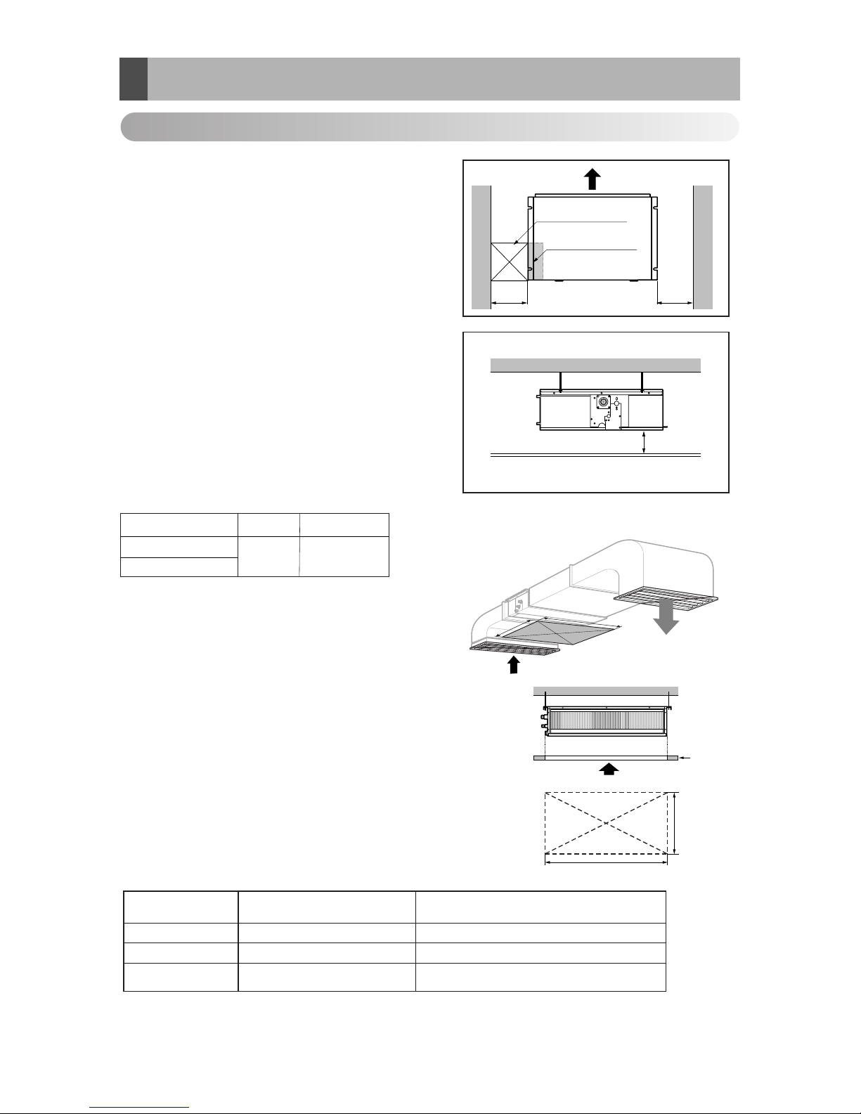
2). Installation of indoor & Outdoor.
Indoor unit
Install the air conditioner in the location that satisfies the following conditions.
• The place shall easily bear a load exceeding four times the
indoor unit’s weight.
• The place shall be able to inspect the unit as the figure.
• The place where the unit shall be leveled.
• The place shall easily connect with the outdoor unit.
• The place where the unit is not affected by an electrical
noise.
• The place where air circulation in the room will be good .
• There should not be any heat source or steam near the
unit
Confirm the positional relationship between the unit and
suspension bolts.
• Installation the ceiling opening to clean the filter or service
under the product.
A).Selection of the best location of Indoor
Inspection hole
(600 x 600)
Control box
H=20 or more
• Suitable dimension "H" is necessary to get a slooe
to drain as aiven in the fiaure
Side view
(unit: mm)
600600
A(Min)
B(Min)
Ceiling
Service Space
A
B
Capacity(Btu/h)
A
B
18/24/30k
600 1100
(Length: mm)
Low static Duct type
Minimum height for motor replacement.
Less than 20cm
Hole size should be
more than the size of IDU.
Insufficient space. Difficult for servicing
20cm to 100cm2
Sufficient space in the ceiling for servicing.
More than 100cm1
Remarks
Distance between
False ceiling & Actual ceiling
Number of
Inspection hole
[Inspection Hole Standard]
36/48/60k
Page 5
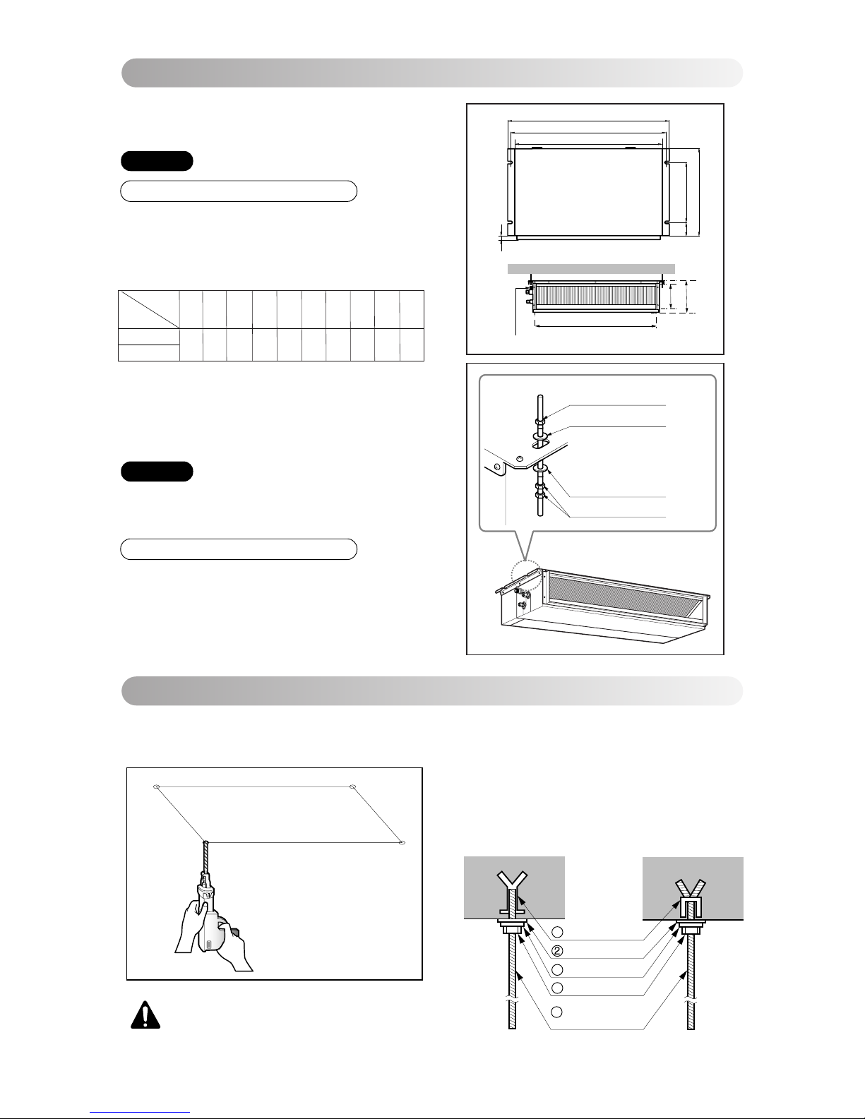
B).Ceiling dimension and hanging bolt location
Installation of Unit
Install the unit above the ceiling correctly.
• Apply a joint-canvas between the unit and duct to absorb
unnecessary vibration.
• Apply a filter Accessory at air return hole.
• Install the unit leaning to a drainage hole side as a figure
for easy water drainage.
• A place where the unit will be leveled and that can support
the weight of the unit.
• A place where the unit can withstand its vibration.
• A place where service can be easily performed.
CASE 1
POSITION OF SUSPENSION BOLT
(Unit:mm)
18/24/30k BTU/h
1130 1180 383 575 93 190 21 1065 163 1100
Dimension
Capacity(Btu/h)
A B C D E F G H I J
CE
G
D
A
J
B
I
F
H
Drainage hole
Drain Pump use
M10 Nut
M10 washer
X 4
X 4
M10 Nut
M10 washer
X 4
X 8
CASE 2
POSITION OF CONSOLE BOLT
5
• Select and mark the position for fixing bolts.
• Drill the hole for set anchor on the face of ceiling.
• Insert the set anchor and washer onto the suspension bolts for locking the suspension bolts on the
ceiling.
•
Mount the suspension bolts to the set anchor firmly.
• Secure the installation plates onto the suspension
bolts (adjust level roughly) using nuts, washers
and spring washers.
1 Set anchor
Old building New building
Plate washer
3 Spring washer
4 Nut
5 Suspension
bolts
Indoor Unit Installation
CAUTION : Tighten the nut and bolt
to prevent unit falling.
36/48/60k BTU/h
Page 6
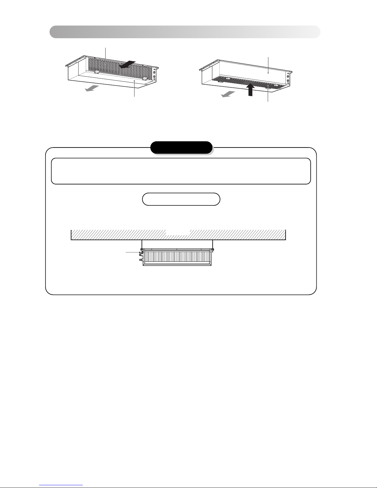
• Low static duct type in case of suction from back
side.
• Low static duct type in case of suction from bottom
side.
Air Filter
Air outlet
Panel Rear
Air outlet
Air Filter
Panel Rear
C).Filter convertible option.
6
CAUTION
Ceiling
Drain Pump use
Drainage hole
Front of view
1. Install declination of the indoor unit is very important for the drain of the duct type air conditioner.
2. Minimum thickness of the insulation for the connecting pipe shall be 19mm.
• The unit must be horizontal or declined to the drain hose connected when finished
installation.
Page 7
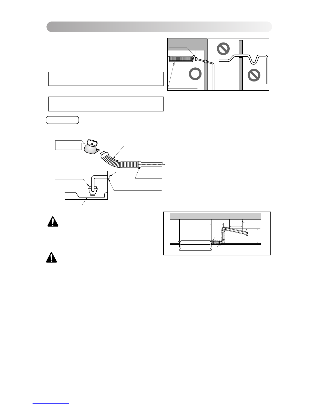
The air conditioner uses a drain pump to drain water.
Use the following procedure to test the drain pump operation:
• Connect the main drain pipe to the exterior
an d leav e it pr ovisi o nally until the te st
comes to an end.
• Feed water to the flexible drain hose and
check the piping for leakage.
• Be sure to check the drain pump for normal
operating and noise when electrical wiring
is complete.
• When the test is comple te, connect the
flexible drain hose to the drain port on the
indoor unit.
Drain test
Feed water
Drain Pump
Drain pan
Flexible drain hose
Main
drain pipe
Glue the joint
Drain
port
Drain hose connection
Use the clip
• Drain piping must have down-slope (1/50 to 1/100): be sure not to
provide up-and-down slope to prevent reversal flow.
• During drain piping connection, be careful not to exert extra force
on the drain port on the indoor unit.
• The outside diameter of the drain connection on the indoor unit is
32mm.
•
Be sure to install heat insulation on the drain piping.
Piping material: Polyvinyl chloride pipe VP-25 and
pipe fittings
Heat insulation material: Polyethylene foam with thickness more than 8 mm.
Upward
routing
not allowed
Pipe clamp
Maintenance
drain port
Indoor unit
D). Drain Piping
7
CAUTION:
After the confirmation of the above conditions, prepare the wiring as follows:
1) Never fail to have an individual power specialized for the air conditioner. As for the method of
wiring, be guided by the circuit diagram posted on the inside of control box cover.
2) Provide a circuit breaker switch between power source and the unit.
3) The screws which fasten the wiring in the casing of electrical fittings are liable to come loose
from vibrations to which the unit is subjected during the course of transportation. Check them
and make sure that they are all tightly fastened. (If they are loose, it could give rise to burn-out
of the wires.)
4) Specification of power source
5) Confirm that electrical capacity is sufficient.
6) Be sure that the starting voltage is maintained at more than 90 percent of the rated voltage
1/50~1/100 slope
Hanger
distance
Hanger Bracket
Max 700mm
Flexible drain hose
Insulation
Metal
clamp
Max 300mm
1~15m
CAUTION : The supplied flexible drain
hose should not be curved, neither
screwed. The curved or screwed hose
may cause a leakage of water.
marked on the name plate.
7) Confirm that the cable thickness is as specified in the power sources specification.
(Particularly note the relation between cable length and thickness.)
8) Never fail to equip a leakage breaker where it is wet or moist.
9) The following troubles would be caused by voltage drop-down.
• Vibration of a magnetic switch, damage on the contact point, fuse breaking, disturbance by the normal function of an overload protection device.
• Proper starting power is not given to the compressor.
Page 8
HAND OVER
Teach the customer the operation and maintenance procedures, using the operation manual.
(air filter cleaning, temperature control, etc.)
4 EA
Name
Quantity
Shape
for gas pipe
for liquid pipe
Clamp metal
2 EA
Insulation for
fitting
1 SET
Drain hose
1 EA
Clamp
(Tie Wrap)
8 EA
Washer for
hanging backet
(Other)
Standard Accessories
• Owner's manual
• Installation manual
8
INSULATION, OTHERS
Insulate the joint and tubes completely.
All thermal insulation must comply with local requirement.
INDOOR UNIT
After all workings are finished, check the working and operation.
• Air distribution ............... Is the air circulation good?
• Drain ............................. Is the drainage smoothly and no sweating?
• Gas leakage ................. Is the piping connection correctly?
• Wiring ........................... Is the wiring connection correctly?
• Lock-bolt ....................... Is the lock-bolt of compressor loosened?
• Insulation Is the unit fully insulated?
• Ground Is the unit safely grounded?
THERMAL INSULATION
TEST AND CHECK
Make sure that there is no clearance here.
Overlap with thermal
insulator for piping.
Thermal insulator for refrigerant pipe
(Local supply)
Thermal insulator for
piping(Local supply)
Hose clip for thermal insulator(Local supply)
Union for gas pipe
Refrigerant pipe and thermal
insulator(Local supply)
Union for liquid pipe
Thermal insulator for refrigerant pipe
(Local supply)
Hose clip for thermal insulator
(Local supply)
Felt
Rubber
Insulation
No clearance
Cabinet
E). Insulation of the Piping & Drain
Page 9

9
B
e
n
z
e
n
e
S
C
O
U
R
I
N
G
C
L
B
A
R
G
E
R
S
I
N
N
E
R
Care and maintenance
Indoor Unit
Caution: Before performing any maintenance, turn off the main power to the system.
Grille, Case, and Remote Control
Turn the system off before cleaning. To clean,
wipe with a soft, dry cloth. Do not use bleach or
abrasives.
Note:
Supply power must be disconnected before
cleaning the indoor unit.
Never use any of the followings:
• Water hotter than 40°C
Could cause deformation and/or
discoloration.
• Volatile substances
Could damage the surfaces
of the air conditioner.
Clean the filter with a vacuum or warm, soapy
water.
• If very dirty, wash with a solution of
detergent in lukewarm water.
• If hot water (50°C or more) is used, filter
may be deformed.
After washing with water, dry well in the shade.
Re-install the air filter.
Air Filter
The air filters behind Indoor unit
(the suction side) should be checked and cleaned
once every 2 weeks or more often if necessary.
1
2
3
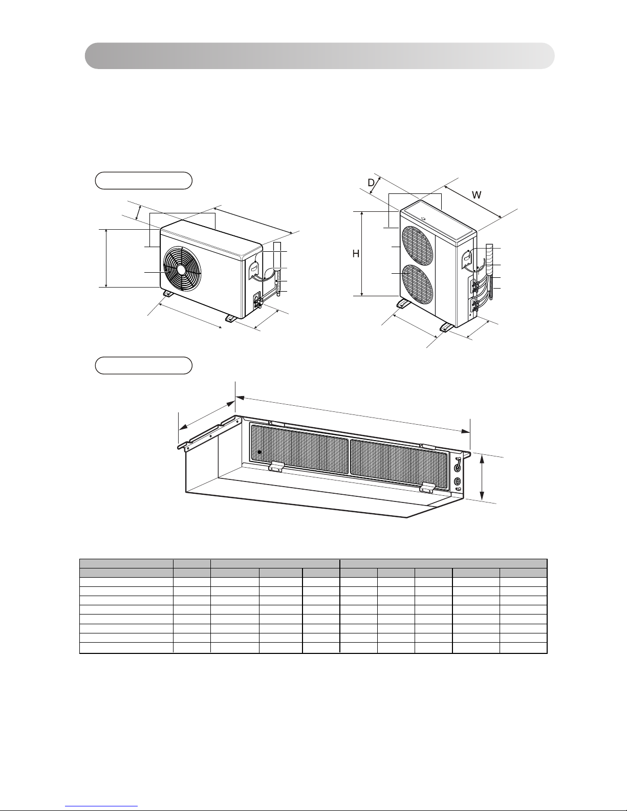
Indoor Unit Dimensions (mm)
CE
G
D
A
J
B
I
F
H
Drainage hole
Drain Pump use
(Unit:mm)
18/24/30k BTU/h
1130 1180 383 575 93 190 21 1065 163 1100
Dimension
Capacity(Btu/h)
A B C D E F G H I J
36/48/60k BTU/h
Page 10
10
F). Outdoor Unit best location & piping.
The heat exchanger coils and panel vents of the
outdoor unit should be checked regularly. If clogged
with dirt or soot, the heat exchanger and panel vents
may be professionally steam cleaned.
Note:
Dirty or clogged coils will reduce the operating
efficiency of the system and cause higher
operating costs.
Outdoor Unit
Indoor Unit
Outdoor Unit
(Side)
(Rear)
Air outlet
vents
Air intake
vents
Connecting Wire
Connection Pipe
Drain Hose
Control Cover
H
D
W
W
H
D
L2
L1
(Rear)
(Side)
Air outlet
vents
Air intake
vents
L1
L2
Connecting Wire
Connection Pipe
Drain Hose
Control Cover
Model Capacity Indoor dimension Outdoor Dimnesion
W D H W D H L1 L2
LB-B2156QC
1.5 TR
1180 575 190 800 260 555 590 305
LB-B2206QC
2 TR
1180 575 190 800 260 555 590 305
LB-B2256QC / LB-B2258QC
2.5 TR
1180 575 190 870 320 655 545 350
JB-B2156QC
1.5 TR
1180 575 190 870 320 655 545 350
JB-B2258QC
2.5 TR
1180 575 190 870 320 800 545 350
LMA36B2ALI
1.5x2 TR
1180 575 190 870 320 655 545 350
LMA48B2ALI
2.0x2 TR
1180 575 190 906 406 1135 606 465
LMA60B2ALI
2.5x2 TR
1180 575 190 906 406 1135 606 465
Page 11
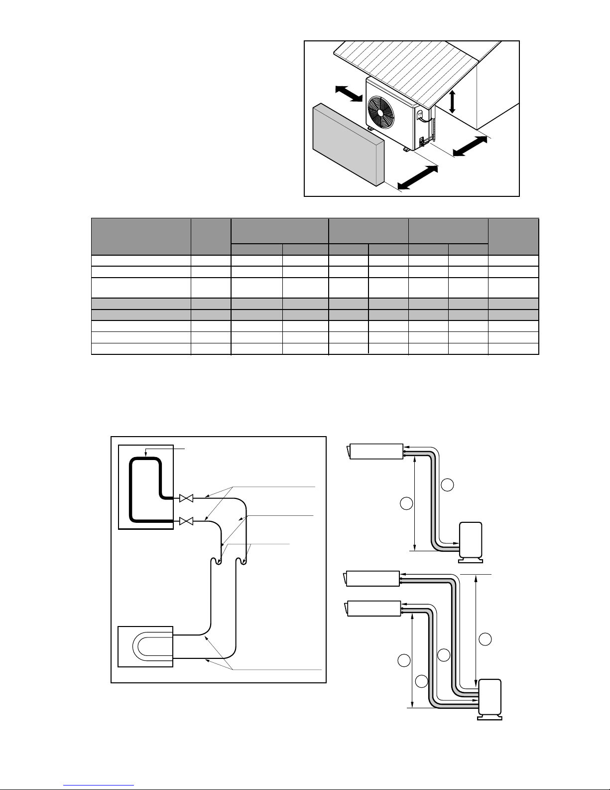
>>Outdoor unit space requirement.
•If an awning is built over the unit to prevent
direct sunlight or rain exposure, be careful
that heat radiation f rom t he condenser is not
restricted.
• There should not be any animals or plants
which could be aff ected by hot air
discharged.
• Ensure the spaces indicated by arrows f rom
the w all, ceiling, f ence or other obstacles.
>>Piping length and the elevation
More than
50cm
More than
50cm
More than
100cm
Sunroof
Fence or
obstacles
• Capacity is based on standard length and maximu m allowance
length is on the basis of reliability .
• Oil trap should be installed every 5 meters.
• If 18K model is installed at a distance of 15m, 150g of refrigerant
should be added [(15-5) x 15g = 150g].
10cm
Gas Liquid standard Max standard Max
1.5 TR 1/2" 1/4" 7.5 30 5 15 R-22 15gm
2 TR 5/8" 1/4" 7.5 30 5 15 R-22 20gm
2.5 TR 5/8" 3/8" 7.5 30 5 15 R-22 25gm
LB-B2156QC
LB-B2206QC
Length(A meter)
Model
Additional
Gas Charge
Pipi Sizes
( Dia In Inch)
Capacity
Elevation(B meter)
1.5 TR 5/8" 3/8" 7.5 80 5 35 R-410 30gmJB-B2156QC
JB-B2258QC 2.5 TR 5/8" 3/8" 7.5 80 5 35 R-410 30gm
11
LB-B2256QC/
LB-B2258QC
LMA36B2ALI 1.5x2 TR 1/2" x 2 1/4"x2 5 30 15 R-22 15gm
LMA48B2ALI 2.0x2 TR 5/8" x 2 1/4"x2 5 30 15 R-22 20gm
LMA60B2ALI 2.5x2 TR 5/8" x 2 3/8"x2 5 30 15 R-22 25gm
5
5
5
Indoor unit
Outdoor unit
B
A
U-Trap
Use seamless pipe
Flared connection (union)
Flared connections
Outdoor
Factory charged gas
Indoor
(Service valves)
Indoor unit
Outdoor unit
B
A
B
A
Page 12
3-1. Preparation of Piping
3. Connecting Pipes to the Indoor Unit
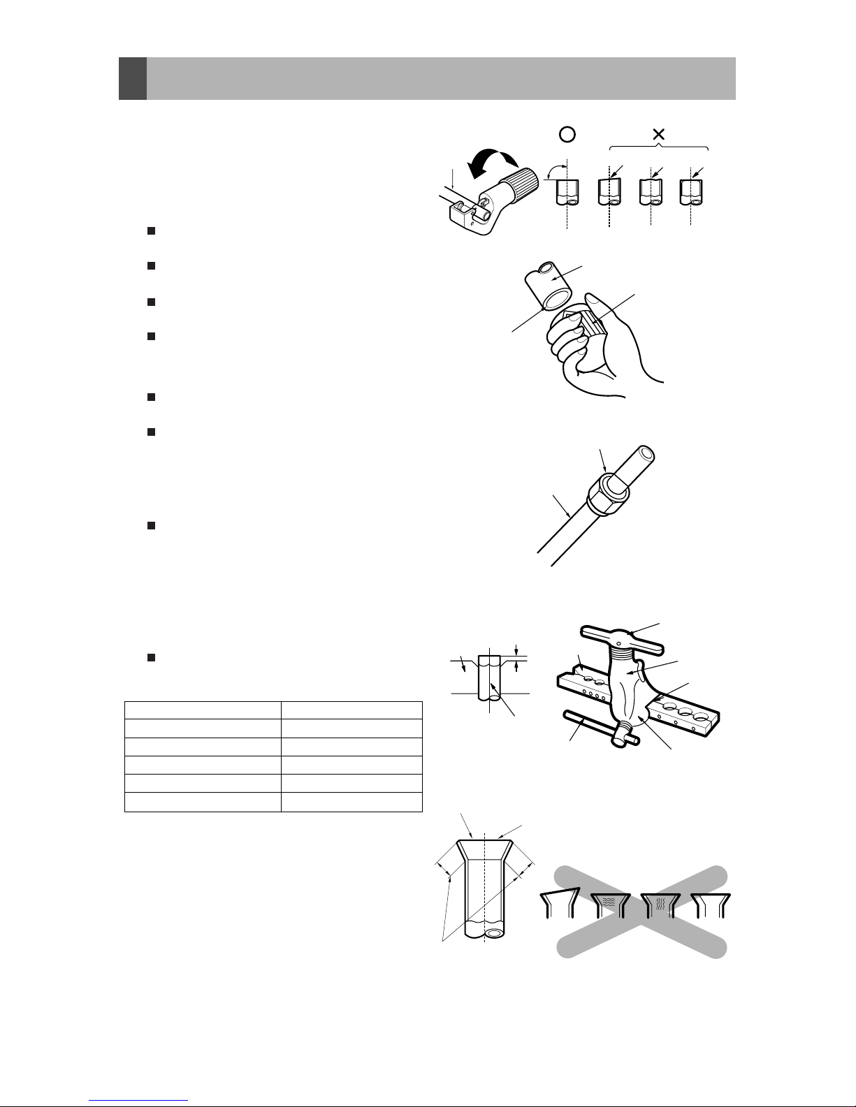
Main cause of gas leakage is defect in
flaring work. Carry out correct flaring work
in the following procedure.
1) Cut the pipes and the cable.
Use the accessory piping kit or the pipes
purchased locally.
Measure the distance between the
indoor and the outdoor unit.
Cut the pipes a little longer than
measured distance.
Cut the cable 1.5m longer than the pipe
length.
2) Burrs removal
Completely remove all burrs from the cut
cross section of pipe/tube.
Put the end of the copper tube/pipe to
downward direction as you remove burrs
in order to avoid to let burrs drop in the
tubing.
3) Putting nut on
Remove flare nuts attached to indoor
and outdoor units, than put them on
pipe/tube having completed burr
removal.
(Not possible to put them on after flaring
work)
4) Flaring work
Carry out flaring work using flaring tool
as shown below.
Firmly hold copper tube in a bar(or die) as
indicated dimension in the table above.
5) Check
Compare the flared work with figure.
If flare is noted to be defective, cut off
the flared section and do flaring work
again.
Copper
tube
90
Slanted Uneven Rough
Pipe
Reamer
Point down
Flare nut
Copper tube
Bar
Copper pipe
Clamp handle
Red arrow mark
Cone
Yoke
Handle
Bar
"A"
Inclined
Inside is shining without scratches.
Smooth all round
Even length
all round
Surface
damaged
Cracked Uneven
thickness
= Improper flaring =
Outside Diameter "A"
1/4" 0~0.5
3/8" 0.5~0.8
1/2" 0.5~0.8
5/8" 0.8~1.0
3/4" 1.0~1.3
12
Page 13

6) Pipe bending
Annealed copper pipe with small diameter (ø6.35 or ø9.52) can be easily bent manually. In
this case, secure large R(radius) for the bend section and gradually bend pipe. If annealed
copper pipe is large in diameter (ø12.7, ø15.88 or ø19.05), bend pipe with bender. Use bender
appropriate for the pipe diameter.
7)
Brazing
In refrigerant piping, bending (in particular, acute bending) must be minimized to reduce
piping resistance. Bending is, however, necessary in some places by virtue of the installation
position of devices
or of
the building structure, piping distance or finishing appearance.
Perform brazing using ready-made elbow. Aside from this function, brazing
perform brazing using ready-made elbow. Aside from this function, brazing
also serves to connect straight pipes, generally using ready-made sockets. While brazing,
protect piping against heat with wet cloth to avoid damaging valve packing or burning
thermal insulator with burner heat. While brazing, blow inert gas (nitrogen gas or carbonic
gas) to prevent formation of oxidation film in copper piping; otherwise, the refrigerant circuit
will clog. The blowing of nitrogen gas (or carbonic gas) through 3-way valves is described in
the following:
8)
Refrigerant piping(Flare piping)
When connecting piping, be sure to keep piping dry(keep piping away from water), clean
(keep piping away from dust) and airtight (avoid refrigerant leakage).
When connecting piping on rainy days or making a through-hole in wall, take due care to
prevent water or plaster from entering piping.
CAUTION
a. This procedure is designed to prevent
formation of oxidation film by filling piping
with inert gas. Note that excessive gas
pressure will generate pinholes at brazed
points.
(Nitrogen gas: Supply pressure
2
0.05~0.1kg/cm
G)
b. When supplying inert gas, be sure to open
one end of piping.
Water enters Plaster enters
13
Page 14

1) Connecting the pipes to the
Outdoor unit
1. Al ign the center of the pipin g s and
sufficiently tighten the flare nut with
fingers.
2. Finally, tightenthe flare nut with torque
wrenchuntilthe wrenchclicks.
• When tightening the flare nut with torque
wrench, ensure the direction for
tightening follows the arrow on the
wrench.
4. Connecting Pipes to the Outdoor Unit
Torque wrench
Outdoor unit
Gas side piping
(Bigger Dia.)
Liquid side piping
(Smaller Dia.)
Pipe size Torque
1/4" 1.8kg.m
3/8" 4.2kg.m
1/2" 5.5kg.m
5/8" 6.6kg.m
3/4" 6.6kg.m
5. IR Remote Sensor Installation & Operation
14
•
Install the IR remote sensor about 6 feet above the floor in an area with good air circulation at an average temperature.
Do not install the IR remote sensor where it can be affected by:
- Drafts, or dead spots behind doors and in corners.
- Hot or cold air from ducts.
- Radiant heat from sun or appliances.
- Concealed pipes and chimneys.
- Uncontrolled areas such as an outside wall
behind the remote controller.
- This IR remote sensor is equipped with
LED display and ON/OFF button. For proper
display of the IR remote sensor
The IR remote sensor should be installed
properly as shown in Fig.1.
(The standard height is 6 feet from floor
level.)
R
e
m
o
t
e
C
o
n
t
r
o
l
l
e
r
T
E
M
P
6feet
no
no
no
Remote Controller
TEMP
Fig.1 Typical locations for IR Remote Sensor
LG
COMP
POWER
FILTER
TIMER
ON/OFF
yes-Optional
Remote Controller
TEMP
yes
Page 15

Installation of IR Remote Sensor
15
1. Connect the IR sensor cable
to the CN-DISPLAY connector
of main PCB Assy.
2. Fix the rear side of the installation board with
the screw.
3. Now attach the IR PCB Assy at the rear
side of installation board.
When disassemble the IR remote sensor
from the installation board, use the driver as
shown in the right picture and insert it into the
hole with the arrow. And when you pull the driver
in the front direction, the IR remote sensor
will be separated.
The IR sensor cable is connected as factory default.
Fixate the IR Remote
Sensor cable to
the guide slot.
Use the screws
for fixate the unit
firmly on the wall.
Installation board
<Front side of
installation board>
<Rear side of
installation board>
Bottom
Wall
Side
Wall
Side
Wall
Side
Wall
Side
Wall
Side
Do not install the cable to be 10m or above.
(It can cause communication error.)
• When installing the extension cable, check the connecting direction of the connector of the IR remote sensor side
and the product side for correct installation.
• If you install the extension cable in the opposite direction, the connector will not be connected.
• Specification of extension cable: AWG 26 (2sim 7shield) or above
Guide slot
Page 16

6). Connecting Cable between Indoor and Outdoor Unit
Perform the electrical wiring work according to
the electrical wiring connection.
• All wiring must comply with local
requirements.
• Select a power source that is capable of
supplying the current required by the air
conditioner.
• Use a recognized circuit breaker
between the power source and the unit.
A disconnection device to adequately
disconnect all supply lines must be
fitted.
• Capacity of circuit breaker
Outdoor
Indoor
Main
power source
Switch box
Circuit Breaker
• Warranty will be null & void if wiring is
not as per installation instructions.
Model Capacity 1 Phase 3 Phase
LB-B2156QC 25 NA
LB-B2206QC 25 NA
LB-B2256QC 32 NA
LB-B2258QC NA 20
JB-B2156QC 25 NA
JB-B2258QC
1.5 TR
2 TR
2.5 TR
2.5 TR
1.5 TR
2.5 TR NA 20
A) Circuit Breaker Detail
LMA36B2ALI 1.5x2 TR 20 x 2 NA
LMA48B2ALI 2.0x2 TR NA
LMA60B2ALI 2.5x2 TR NA 32
Outdoor
Indoor
Main
power source
Circuit Breaker
Circuit Breaker
20 x 2
16
Page 17

Indoor Wiring Diagram :
Model :
LB-B2156QC /
LB-B2206QC /
LB-B2256QC /
LB-B2258QC /
LMA36B2ALI /
LMA48B2ALI /
LMA60B2ALI
(R-22 Gas Charge
Model)
TO
INDOOR
INPUT MAINS/SUPPLY
(1ø,230V)
L N E L N
S
1 2 3 4 5 6
RD
BK
A1
A2
L1
L2
T1
T2
Magnetic
Contractor
BK
RD
BK
WH
T/B
Out
Motor
GR
OR
COMP
RD
C
S
R
BK
YL
H
F
C
3854A20298J
OUTDOOR WIRING DIAGRAM
FROM
INDOOR
RD
GR
BK
BK
BL
Outdoor Wiring Diagram :
Model :
LB-B2256QC
(R-22 Gas
Charge Model)
B) Wiring Diagram
Model : LB-B2258QC
(R-22 Gas charge Model)
3854A20298Q
In door & Out door connection detail
INDOOR OUTDOOR
Terminal No.
1
2
3
7
8
PHASE IN (R)
PHASE IN (S)
PHASE IN (T)
NEUTRAL IN
GND IN
1
2
3
4
5
6
9
10
11
PHASE
NEUTRAL
COMP
GND
PHASE
NEUTRAL
COMP
GND
3ø415 V
Power Supply
NORMAL CROSS-SECTIONAL AREA
WIRE NO. SPECIFICATION
1,2,3,7 & 8
9,10 & 11
2
3.5 mm
2
1.25 mm
5 CORE
3 CORE
T1
T2
T3
RD WH BK
COMP
L1 L2 L3
A2
A1
T1 T2 T3
Magnetic
Contactor
BL
YL
RD
RD
18 15
BL
YL
RD
RD
BK
TERMINAL A
1R2S3
T
MOTOR
1
ORANGE
CAPACITOR 1
YELLOW
BK
TERMINAL C
TERMINAL B
7
NGL
8910 11 12
From Indoor
Signal
(3ø, 415V)
Power Supply
3ø 415V
Power Supply
OUTDOOR WIRING DIAGRAM
BLACK
To Indoor
(1ø, 230V)
BK
L3 L2 L1
3ø, MONTORING RELAY
BK
RD
N
S
Model :
LB-B2156QC /
LB-B2206QC
(R-22 Gas
Charge Model)
TO
INDOOR
INPUT MAINS/SUPPLY
(1ø,230V)
L N E L N
S
1(L)
4 5 6
RD
BK
0
1
2
6
4
8
Power
Relay
BK
RD
YL
WH
T/B
Out
Motor
GR
BL
COMP
RD
C
S
R
BK
RD
H
F
C
3854A20298U
OUTDOOR WIRING DIAGRAM
FROM
INDOOR
RD
GR/YL
BK
BK
BR
2(N)
17
NOTE : Connect IR PCB Assy. at CN-DISP of PCB Assy.
Page 18

Outdoor Wiring Diagram :
Model : LMA36B2ALI (R-22 Gas Charge Model)
Outdoor Wiring Diagram :
Model : LMA48B2ALI (R-22 Gas Charge Model)
Outdoor Wiring Diagram :
Model : LMA60B2ALI (R-22 Gas Charge Model)
C
S
R
FAN
MOTOR
R
S
C
COMP. 2
OR
BK
5
RD
BR
BK
RD
RD
RD
COMP. 1
S
R
C
WH
RD
RD
OR
TB
1
CAP 1
BK
HCF
BL
BL
BK
RD
WH
TB
2
CAP 2
H
C
F
RD/BR
BK/BL
RD/BR
BK/BL
8 2 0
1
6 4
L1 N1
RD/BR
BK/BLRDBK
SIGNAL
(1ø, 230V)
INPUT MAINS SUPPLY UNIT 1
TO INDOOR
UNIT 1
OUTDOOR WIRING DIAGRAM
(1ø, 230V)
INPUT MAINS SUPPLY UNIT 2
RD/BR
BK/BL
N2
L2
8 2 0
1
46
3854A20298X
CAP3
GR
1 2 3 4 5 6
RDBKSIGNAL
TO INDOOR
UNIT 2
RD/BR
BK/BL
BK/BL
RD/BR
BK/BL
RD
GR
BK/BL
BK/BL
RD/BR
RD
BK/BL
RD/BR
3854A20298Y
FAN
MOTOR2
R
C
S
OR
YL
RD
H
C F
CAP 2
BK
BK
R
S
COMP. 2
C
WH
TB4
BK
TB3
RD
RD
RD
8 2 0
146
BK
BK
BR
GR/YL
BK
RD
TERMINAL
BLOCK (B)
7 8 9 10 11 12
RD/BR
BK/BL
GREEN
RD
BK
SIGNAL
(1Ø, 230V)
INPUT MAINS SUPPLY
TO INDOOR
FAN
MOTOR1
R
C
S
OR
YL
RD
H
C F
CAP 1
BK
BK
R
S
COMP. 1
C
WH
TB2
BK
TB1
RD
RD
RD
8 2 0
146
BK
BK
BR
GR/YL
BK
RD
TERMINAL
BLOCK (A)
1 2 3 4 5 6
RD/BR
BK/BL
GREEN
RD
BK
SIGNAL
(1Ø, 230V)
INPUT MAINS SUPPLY
TO INDOOR
OUTDOOR WIRING DIAGRAM
OUTDOOR WIRING DIAGRAM
TERMINAL (A)TERMINAL (B)
12
B
3Ø415 V
POWER SUPPLY
NGY R
TO
INDOOR 1
1Ø230 V
4
6
5
23 1
911 1078
BK
28
3
2
1
YL
27
BK
20
RD
BK
20
5
4
L1
15
RD
28
BL
L3
25
BL
6
L2
18
21
21
BL YL RD
A2
A1
BL
WH
BK
V
COMP(2)
W
WH
COMP(1)
BK
V
W
U
RD
Magnetic
Contactor
L1 L2
Magnetic
Contactor
L1 L21L3
2
L3
RD
U
RD
T3
11
11
BK
9
T1
BL8YL
T2
YLT2BLT1RD
T3
7
Magnetic Contactor(1)
Magnetic Contactor(2)
A1
A2
GN/YL
3ø MONITORING
RELAY
BK
GND
BLACK
MOTOR MOTOR
1
2
C
S
R
C
S
YELLOW
YELLOW
ORANGE
ORANGE
BLACK
CAPACITOR1CAPACITOR
2
BK11BK
11
1
2
BK
9
7
BR
7
BR
R
3
4
28
BK
GN/YL
FROM
INDOOR
SIGNAL 2
TO
INDOOR 2
1Ø230 V
FROM
INDOOR
SIGNAL 1
S2
N2 P2S1N1 P1
G
3854A20298T
18
Page 19

3854A20298K
CN-FLOAT
CONTROLLER
CN-PIPE/IN
RY-D/PUMP
FUSE 250V
3.15A
CN-POWER
RD
BL
BR
BK
CN-VM
CN-PTC
FROM OUTDOOR
CN-DISP
CN-DISPLAY
NOTE: 1) For ANONE1 Model Suffix, CN-DISP is Optional.
2) For ANONE2 Model Suffix, WIRED REMOTE CONTROLLER
& DRAIN PUMP is Optional.
SENSOR
JUMPER
SENSOR
ASSY.
Indoor Wiring Diagram :
Model : JB-B2156QC (R410 Gas Charge Model)
Outdoor Wiring Diagram :
Model : JB-B2156QC (R410 Gas Charge Model)
1ph 230V
To
Indoor
3 2 1
GR
BR
BL
HP
SWITCH
4 5 6 78 9
BR
GR
GR
BL
BR
BL
BL
BR
BL
Magnetic
Contactor
A1
A2
L1
L2
T1
T2
BK
T/B1BKT/B2
WH
OUT
MOTOR
OR(GR)
GR
C
S
R
RD
COMP
YL
BK
H
C
F
OUTDOOR WIRING DIAGRAM
3854A20372B
FUSE
19
NOTE : Connect IR PCB Assy. at CN-DISP of PCB Assy.
Page 20

3854A20298K
CN-FLOAT
CONTROLLER
CN-PIPE/IN
RY-D/PUMP
FUSE 250V
3.15A
CN-POWER
RD
BL
BR
BK
CN-VM
CN-PTC
FROM OUTDOOR
CN-DISP
CN-DISPLAY
NOTE: 1) For ANONE1 Model Suffix, CN-DISP is Optional.
2) For ANONE2 Model Suffix, WIRED REMOTE CONTROLLER
& DRAIN PUMP is Optional.
SENSOR
JUMPER
SENSOR
ASSY.
Indoor Wiring Diagram :
Model : JB-B2258QC (R410 Gas Charge Model)
Outdoor Wiring Diagram :
Model : JB-B2258QC (R410 Gas Charge Model)
TERMINAL
B
L N
G
S
N
To Indoor
(1Ø,230V)
From Indoor
R
S
213 6
54 1
2 3
T
TERMINAL A
3Ø 415V
Power Supply
R
D
WH
BK
T2
COMP
T1
T
3
T2
Magnetic
Contactor
L1T1L2
L3
T3
A1
A2
TERMINAL C
MOTOR
1
ORANGE
CAPACITOR
YELLOW
RD
RD
BK
RD
Y
L
BL
BK
YL
BL
3854A20396B
RD
BL
RD
RD
RD
BK
BK
3ø MONITORING
RELAY
1518
L1L2L3
34
34
RD
RD
35
HP
SWITCHLPSWITCH
20
NOTE : Connect IR PCB Assy. at CN-DISP of PCB Assy.
Page 21

21
Connecting Cables between Indoor and Outdoor Unit
1) Connecting cables to the Indoor Unit
Connect the wires to the terminals on the control board individually according to the
outdoor unit connection.
Ensure that the color of the wires of outdoor unit and the terminal No. are the same as
those of indoor unit respectively
2) Clamping of cables
1) Arrange 2 power cables on the control panel.
2) First, fasten the steel clamp with a screw to the inner boss of control panel.
3) For the cooling model, fix the other side of the clamp with a screw strongly.
The power cord connected to the outdoor unit should be
with the following specifications
If the supply cord is damaged, it must be replaced by a special cord or assembly availible from the manufacturer of its service agent.
The connecting cable connected to the indoor and outdoor
unit should be with the following specifications
CAUTION
20mm
G
N/YL
NORMAL
CROSS-SECTIONAL
AREA
1.25mm
2
(18/24K)
20mm
GND
Capacity
18/24
K BTU/h
1 Phase
2.5mm
2
NORMAL CROSS-SECTIONAL AREA
Make sure that the screws of the terminal are free from looseness.
WARNING
18/24/30K BTU/h
Applied Model:- LB-B2156QC,LB-B2206QC,LB-B2256QC, JB-B2156QC.
1) Input 1-phase power supply into outdoor & wire specification.
1
2
GND
L N GND
Outdoor terminal block
2) For connection between of Indoor and Outdoor unit & wire specifiacation
Indoor terminal block
1 2
GND
3
4
5
GND
6
Outdoor terminal block
RD BK GND BR
Wire specification.
Wire specification.
Model Capacity 1 Phase No of core
LB-B2156QC 1.5 tr 1.5 mm2 4
LB-B2206QC 2 TR 1.5 mm2 4
LB-B2256QC 2.5 TR 1.5 mm2 4
JB-B2156QC 1.5 TR 1.5 mm2 4
Model Capacity
1 Phase
mm2 * core
LB-B2156QC 1.5 tr 2.5 mm2*3
LB-B2206QC 2 TR 2.5 mm2*3
LB-B2256QC 2.5 TR 2.5 mm2*3
JB-B2156QC 1.5 TR 2.5 mm2*3
Note : GND = Ground Earthing
1 2
GND
3
5
6
4
7
RD BK GND BR
A) LB-B2156QC, LB-B2206QC, LB-B2256QC B) JB-B2156QC
Page 22

22
1) Connecting cables to the indoor Unit
Connect the wires to the terminals on the control board individually according to the
outdoor unit connection.
Ensure that the color of the wires of outdoor unit and the terminal No. are the same as
those of indoor unit respectively.
2) Clamping of cables
1) Arrange 2 power cables on the control panel.
2) First, fasten the steel clamp with a screw to the inner boss of control panel.
3) For the cooling model, fix the other side of the clamp with a screw strongly.
The power cord connected to the outdoor unit should be
with the following specifications
If the supply cord is damaged, it must be replaced by a special cord or assembly availible from the manufacturer of its service agent.
The connecting cable connected to the indoor and outdoor
unit should be with the following specifications
CAUTION
Capacity
30K BTU/h
3 Phase
2.5mm
2
NORMAL CROSS-SECTIONAL AREA
Make sure that the screws of the terminal are free from looseness.
WARNING
1) Input 3-phase power supply into outdoor, cable specification 4 core 2.5 sq mm2 & Separable
Earthing Wire.
1
2
3
R Y
GND
2) For connection between of Indoor and Outdoor unit & wire specification 4 core , 1.25 sq mm2 .
Outdoor terminal block
2 3 4 5
1 2 3 GND
Terminal B
Indoor terminal block
RD BK BR GND
30K BTU/h
Applied Model:- JB-B2258QC / LB-B2258QC.
Outdoor terminal block B
5 6
Outdoor terminal block A
Connecting Cables between Indoor and Outdoor Unit
B
NORMAL
CROSS-SECTIONAL
AREA
1.25mm
2
(30K)
20mm
GND
20mm
N
Note : GND = Ground Earthing
Note : GND = Ground Earthing
JB-B2258QC LB-B2258QC
R Y
Outdoor terminal block B
7 8
Outdoor terminal block A
B
GNDN
JB-B2258QC
8 9 10 11
1 2 3
GND
Terminal B
GND RD BK BR
LB-B2258QC
1 2 3
Page 23

23
Connecting Cables between Indoor and Outdoor Unit
1) Connecting cables to the Indoor Unit
Connect the wires to the terminals on the control board individually according to the
outdoor unit connection.
Ensure that the color of the wires of outdoor unit and the terminal No. are the same as
those of indoor unit respectively
2) Clamping of cables
1) Arrange 2 power cables on the control panel.
2) First, fasten the steel clamp with a screw to the inner boss of control panel.
3) For the cooling model, fix the other side of the clamp with a screw strongly.
The power cord connected to the outdoor unit should be
with the following specifications
If the supply cord is damaged, it must be replaced by a special cord or assembly availible from the manufacturer of its service agent.
The connecting cable connected to the indoor and outdoor
unit should be with the following specifications
CAUTION
20mm
G
N/YL
NORMAL
CROSS-SECTIONAL
AREA
1.25mm
2
(36/48K)
20mm
GND
Capacity
36/48
K BTU/h
1 Phase
2.5mm
2
NORMAL CROSS-SECTIONAL AREA
Make sure that the screws of the terminal are free from looseness.
WARNING
36/48K BTU/h
Applied Model:- LMA36B2ALI, LMA48B2ALI
1) Input 1-phase power supply into outdoor & wire specification.
2) For connection between of Indoor and Outdoor unit & wire specification
Indoor terminal block
1
2
3
1
2
3
Outdoor terminal block
RD BK BR
Wire specification.
Model Capacity 1 Phase No of core
LMA36B2ALI 1.5 TR x 2 1.5 mm2 4
LMA48B2ALI 2 TR x 2 1.5 mm2 4
Note : GND = Ground Earthing
A) LMA36B2ALI
2
1
N L GND
Outdoor terminal block
Wire specification.
Model Capacity
1 Phase
mm2 * core
LMA36B2ALI 1.5TR x 2 2.5 mm2*3
LMA48B2ALI 2TR x 2 2.5 mm2*3
2
1
NLGND
Unit-1 Unit-2
10
11
L N GND
3
2
GNDNL
Unit-1 Unit-2
1 12
GND
1
2
3
3
4
5
6
B) LMA48B2ALI
GND
1
2
3
9
10
11
12
GND
Unit-1
Unit-1
1 2 3
4 5 6
BR
BK
RD
GND
Unit-2
Unit-2
Unit-1 Unit-2
Unit-1 Unit-2
A) LMA36B2ALI B) LMA48B2ALI
RD BK BR RD BK BR
Page 24

24
1) Connecting cables to the indoor Unit
Connect the wires to the terminals on the control board individually according to the
outdoor unit connection.
Ensure that the color of the wires of outdoor unit and the terminal No. are the same as
those of indoor unit respectively.
2) Clamping of cables
1) Arrange 2 power cables on the control panel.
2) First, fasten the steel clamp with a screw to the inner boss of control panel.
3) For the cooling model, fix the other side of the clamp with a screw strongly.
The power cord connected to the outdoor unit should be
with the following specifications
If the supply cord is damaged, it must be replaced by a special cord or assembly availible from the manufacturer of its service agent.
The connecting cable connected to the indoor and outdoor
unit should be with the following specifications
CAUTION
Capacity
60K BTU/h
3 Phase
2.5mm
2
NORMAL CROSS-SECTIONAL AREA
Make sure that the screws of the terminal are free from looseness.
WARNING
1) Input 3-phase power supply into outdoor, cable specification 4 core 2.5 sq mm2 & Separable
Earthing Wire.
2) For connection between of Indoor and Outdoor unit & wire specification 4 core , 1.25 sq mm2 .
60K BTU/h
Applied Model:- LMA60B2ALI
Connecting Cables between Indoor and Outdoor Unit
NORMAL
CROSS-SECTIONAL
AREA
1.25mm
2
(60K)
20mm
GND
20mm
Note : GND = Ground Earthing
LMA60B2ALI
Outdoor terminal block
Note : GND = Ground Earthing
3 2 1
4
B Y RNGND
5
Indoor terminal block
1 2 3
12 11 10
Outdoor terminal block
BR
GND
Unit-2 Unit-1
Unit-2 Unit-1
BK RD
321
789
RD
GND
BKBR
Page 25

1. Remove the Cover control from the unit
by loosening a screw.
Connect the wires to the terminals on
the control board individually as
following.
2. Secure the cable onto the control board
with the holder (clamper).
3. Refix the cover control to the original
position with the screw.
25
CAUTION
After the confirmation of the above conditions, prepare the wiring as follows:
1) Never fail to have an individual power specialized for the air conditioner. As for the method
of wiring, be guided by the circuit diagram pasted on the inside of control box cover.
2) Provide a circuit breaker switch between power source and the unit.
3) The screw which fasten the wiring in the casing of electrical fittings are liable to come
loose from vibrations to which the unit is subjected during the course of transportation.
Check them and make sure that they are all tightly fastened. (If they are loose, it could give
rise to burn-out of the wires.)
4) Specification of power source
5) Confirm that electrical capacity is sufficient.
6) Be sure that the starting voltage is maintained at more than 90 percent of the rated voltage
marked on the name plate.
7) Confirm that the cable thickness is as specified in the power sources specification.
(Particularly note the relation between cable length and thickness.)
8) Never fail to equip a leakage breaker where it is wet or moist.
9) The following troubles would be caused by voltage drop-down.
• Vibration of a magnetic switch, damage on the contact point there of, fuse breaking,
disturbance to the normal function of a overload protection device.
• Proper starting power is not given to the compressor.
Cord Clamper
Power supply
cord
Cover control
Terminal block
Outdoor unit
Over 5mm
C) Outdoor Wiring Routine and Pipe Routine
Page 26

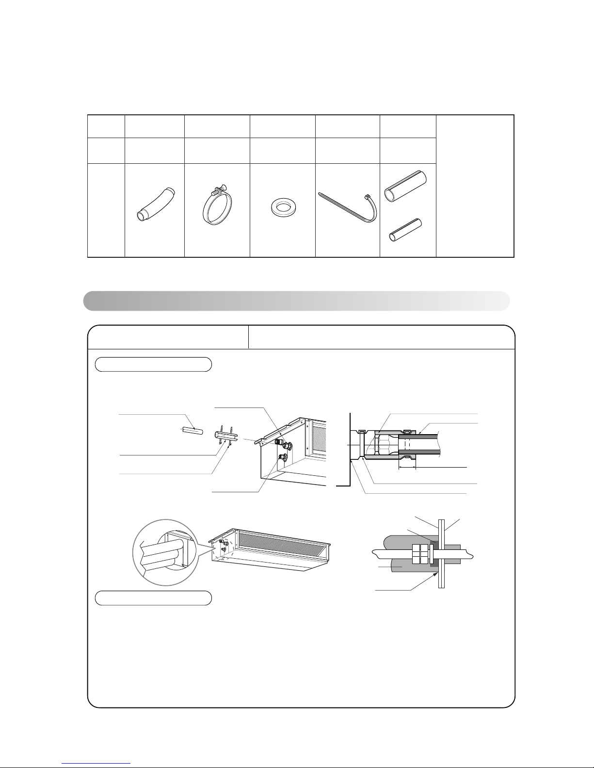
>> Piping Routine
1. Wrap the connecting portion of indoor
unit with the Insulation material and
secure it with two Plastic Bands. (for the
right pipings)
• If you want to connect an additional drain
hose, the end of the drain-outlet should
keep distance from the ground. (Do not
dip it into water, and fix it on the wall to
avoid swinging in the wind.)
2. Tape t h e Pipin g s, drain h os e and
Connecting Cable from bottom to top.
3. Form the pipings gathered by taping
along the exterior wall and fix it onto the
wall by saddle or equivalent.
2. Tape the Pipings and Connecting cable
from bottom to top.
3. Form the pipings gathered by taping
along the exterior wall, and make the
trap prevent water from entering into the
room.
4. Fix the pipings onto the wall by saddle
or equivalent.
26
In case of the Outdoor unit being installed
below position of the Indoor unit.
In case of the Outdoor Unit being installed
above position of the Indoor Unit.
Trap is required to prevent water from entering
into electrical parts.
Seal a small opening
around the pipings
with gum type sealer.
Drain hose
Taping
Pipings
Connecting
cable
Power supply
cord
Seal a small opening
around the pipings
with gum type sealer.
Trap
Page 27

7. Air Purging of the Connecting Pipes and the Indoor Unit
27
Indoor unit
Liquid side
Outdoor unit
OPEN CLOSE
Vaccum pump
Gas side
Closed
Closed
2-way valve/
3-way valve
3-way
valve
The air which contains moisture remaining in the refrigeration cycle may cause a malfunction
on the compressor.
1. Confirm that both the liquid side valve and the gas side valve are set to the closed position.
2. After connecting the piping, check the joints for gas leakage with gas leak detector.
3. Remove the service port nut, and connect the gauge manifold and the vacuum pump to the
service port by the charge hose.
4. Vacuum the indoor unit and the connecting pipes until the pressure in them lowers to below 76cmHg.
5. Remove the valve stem nuts, and fully open the stems of the 2-way and 3-way valves with a
hexagon wrench.
6. Tighten the valve stem nuts of the 2-way valve and 3-way valve.
7. Disconnect the charge hose and fit the nut to the service port.
(Tightening torque: 1.8kg.m)
Page 28

8. Operating Instructions
A) Indoor Unit, Outdoor Unit
Outdoor Unit
Air Intake
(side, rear)
Connecting Wire
Drain Hose
Power Wire
Connection Tube
Air Outlet
Vents
Cooling model: Low static Type Air Conditioner for cooling
Wired Remote
Controller (Optional)
Operation Indication Lamps
Wireless Remote Receiver & Controller
(Standard)
6
LG
COMP
POWER
FILTER
TIMER
ON/OFF
4
2
5
3
1
Signal Recepter
28
LG
COMP
POWER
FILTER
TIMER
ON/OFF
Forced Operation : Use the ON/OFF button when remote control is not available.
TIMER
: Lights up during timer operation.
Signal Receptor
: Receives the signal from remote control (signal receiving sound:
switch on)
one long beep)
FILTER SIGN
: Lights up after 240 hours from the time of first power on operation.
1
2
3
4
COMP
ON/OFF
: Lights up during outdoor operation (i.e. when compressor
: Lights up during system operation.
5
6
Page 29

B) Remote Control Preparation
29
Page 30

C) Remote Control Operations
The remote control transmits the signals to the system.
Features of the Remote Control- Door Closed
1
START/STOP BUTTON
Operation starts when this button is
pressed and stops when the button is
pressed again.
2
OPERATION MODE
SELECTION BUTTON
Used to select the operation mode.
ROOM TEMPERATURE
SETTING BUTTONS
Used to select the room temperature.
3
Operation Mode
Cooling Operation
Auto Operation
Healthy Dehumidification Operation
Cooling Operation
Auto Operation
Healthy Dehumidification Operation
Heating Operation
(Cooling Model) (Heat Pump Model)
* Your unit shall have either Type A or Type B Remote Control.
ON
Signal transmitter
Flip-up door
(closed)
2
4
5 1
3
ON
Signal transmitter
Flip-up door
(closed)
2
4
5 1
3
JET COOL
A/SWING
POWER
TEMP
FAN SPEED
MODE
TYPE A TYPE B
66
30
4
INDOOR FAN SPEED
SELECTOR
Used to select fan speed in four steps
low, medium, high, or CHAOS.
JET COOL
Used to start or stop the speed
cooling. (Speed cooling operates
super high fan speed in cooling mode).
5
AIR SWING BUTTON
Used to stop or start louver movement and
set the desired up/down airflow direction.
6
For low static duct unit, CHAOS speed is not available.
For low static duct unit, JET COOL function is not available.
For low static , is not available.duct unit AIR SWING function
Page 31

Features of the Remote Control- Door Opened
1
ON/OFF TIMER BUTTONS
Used to set the time of starting and stopping
operation.
2
TIME SETTING BUTTONS
Used to adjust the time, (See page 38)
TIMER SET/CANCEL BUTTONS
Used to set the timer when the desired time is
obtained and to cancel the Timer operation.
(See page 38)
3
4
SLEEP MODE AUTO BUTTON
Used to set Sleep Mode Auto operation.
(See page 38)
AIR CIRCULATION BUTTON
Used to circulate the room air without cooling
or heating. (See page 39)
5
ROOM TEMPERATURE
CHECKING BUTTON
Used to check the room temperature.
6
7
88
RESET BUTTON
Used prior to resetting time or after replacing
batteries.
ON
OFF
CANCEL
SET
3
4
6
1
2
7
5
Flip-up door
(opened)
Signal
transmitter
3
4
6
1
2
7
5
Flip-up door
(opened)
Signal
transmitter
JET COOL
A/SWING
POWER
TEMP
FAN SPEED
MODE SLEEP CANCEL
TIMERON OFF SET
FAN ROOM
TIMER
8
8
2ndF BUTTON
Used prior to using modes printed in blue at
the bottom of buttons.(See page 37)
31
Page 32

ON
Cooling
To lower the temperature
To raise the temperature
Press the Start/Stop button.
The unit will respond with
a beep.
Open the door of the remote controller. To select Cooling
Operation, press the Operation Mode Selection button.
Each time the button is pressed, the operation mode is
shifted in the direction of the arrow.
Close the door of the remote controller. Set the temperature
lower than the room temperature. The temperature can be
set within a range of 18°C~30°C at intervals of 1°C.
Set the fan speed again with the door
of the remote controller still closed.
You can select the fan speed in 3
steps-low, medium, & high.
Each time the button is pressed, the
fan speed mode is shifted.
1
2
3
4
Cooling operation
A/SWING
POWER
TEMP
FAN SPEED
JET COOL
ON
MODE
Healthy
Dehumidification
Heating
(Heat pump model only)
Auto
32
CHAOS speed is not available for low static duct unit.
*
Page 33

Cooling
Healthy
Dehumidification
Auto
Heating
(Heat pump model only)
To lower the temperature
To raise the temperature
Press the Start/Stop button.
The unit will respond with
a beep.
Open the door of the remote controller. To select Auto
Operation, press the operation mode selection button.
Each time the button is pressed, the operation mode is
shifted in the direction of the arrow.
The temperature and fan speed are automatically set by the
electronic controls based on the actual room temperature. If
you want to change the set temperature, press the Room
Temperature Setting buttons. The cooler or warmer you feel,
the more times (up to two times) you should press the button.
The set temperature will be changed automatically.
During Auto Operation
You cannot control the indoor fan speed. It has already been set by the Fuzzy rule.
If the system is not operating as desired, manually switch to another mode. The system will not
automatically switch from the cooling mode to the heating mode, or from heating mode to cooling
mode, it must be done by manually resetting.
1
2
3
A/SWING
POWER
TEMP
FAN SPEED
JET COOL
ON
MODE
ON
33
Auto operation (Optional)
CHAOS speed is not available for low static duct unit.
*
Page 34

Cooling
Press the Start/Stop button.
The unit will respond with
a beep.
Open the door of the remote controller. To select Healthy
Dehumidification Operation, press the Operation Mode
Selection button.
Each time the button is pressed, the operation mode is
shifted in the direction of the arrow.
1
2
Set the fan speed again with the door
of the remote controller still closed.
You can select the fan speed in 3
steps-low, medium, high. Each time
the button is pressed, the fan
speed mode is shifted.
3
Healthy dehumidification operation
During Healthy Dehumidification Operation
If you select the dehumidification mode on the operation selection button, the product starts to run the
dehumidification function. It automatically sets the room temp. and airflow volume to the best condition
for dehumidification, based on the sensed current room temp.
In this case, however, the setting temp. is not displayed on the remote controller and you are not able to
control the room temp. either.
During the healthy dehumidification function, the airflow volume is automatically set according to the
optimization algorithm responding to the current room temp. status, so that the room condition is kept
healthy and comfortable even in the very humid season.
A/SWING
POWER
TEMP
FAN SPEED
JET COOL
ON
MODE
ON
Healthy
Dehumidification
Heating
(Heat pump model only)
Auto
34
CHAOS speed is not available for low static duct unit.
*
Page 35

Cooling
Press the Start/Stop button.
The unit will respond with
a beep.
Open the door of the remote controller. To select Heating
Operation, press the Operation Mode Selection button.
Each time the button is pressed, the operation mode is
shifted in the direction of the arrow.
To lower the temperature
To raise the temperature
Close the door of the remote controller.
Set the temperature higher than the room temperature.
The temperature can be set within a range of 18°C~30°C at
intervals of 1°C.
Set the fan speed again with the door of the
remote controller still closed. You can
select the fan speed in Three steps–low,
medium, & high. Each time the button is
pressed, the fan speed mode is shifted.
1
2
3
4
ON
ON
MODE
A/SWING
POWER
TEMP
FAN SPEED
JET COOL
Healthy
Dehumidification
Heating
(Heat pump model only)
Auto
35
Heating operation (Heat pump model only)
Page 36

or or
During the JET COOL function at any moment, the A/C starts to blow the cool air at extremely
high speed for 30 minutes setting the room temp. automatically to 180C. It is especially used to
cool the room temp. quickly in a hot summer.
In heat pump mode or auto changeover mode, however, the JET COOL function is not available.
In order to return to the normal cooling mode from the JET COOL mode, just press the operation
mode selection button, airflow volume selection, temp. setting button or the JET COOL button
again.
NOTICE
Press the Start/Stop button.
The unit will respond with
a beep.
Press the Jet Cool button to operate
the speed cooling mode and the unit
will operate at super high fan speed
on cooling mode for 30 minutes.
To cancel the Jet Cool mode, press the Jet Cool buttons,
1
2
3
A/SWING
POWER
TEMP
FAN SPEED
JET COOL
JET COOL function is not available for LS duct models.
36
The fan speed button or the room temperature setting
button again and the unit will operate at high fan speed
on cooling mode.
Jet cool operation (optional)
Page 37

2nd F operation
Press the Start/Stop button.
The unit will respond with
a beep.
Open the door of the remote controller and press the 2nd
Function button to operate functions printed blue color under
buttons.
(Check the indication of 2nd function on the display of the
remote controller.)
2nd function disappears in a short time automatically or when
the button is pressed again.
1
2
3
For more details, refer to functions next pages.
JET COOL
A/SWING
POWER
TEMP
FAN SPEED
MODE SLEEP CANCEL
TIMERON OFF SET
FAN ROOM
TIMER
ON
OFF
CANCEL
SET
37
Page 38

Delay OFF Timer Delay ON Timer Delay OFF and ON Timer Delay ON and OFF Timer
Sleep mode
1. Press the Sleep Mode Auto button to set the time you want the unit to stop automatically.
2. The Timer is programmed in one-hour increments by pressing the Sleep Mode Auto button 1 to 7 times. The
sleep mode is available for 1 to 7 times. To alter the time period in steps of 1 hour, press the Sleep Mode
Button while aiming at air conditioner.
3. Make sure the Sleep Mode Auto LED lights up.
To cancel the Sleep Mode, press the sleep Mode Auto button several times until the star
( ) disappears from the operation display.
The Sleep Mode will be operated at slow fan speed (cooling)
or medium fan speed (heat pump only) for
a comfortable sleep.
NOTICE
Setting the time
1. Time can be set only when you press the Reset button. Having replacing the batteries,
you should press the reset buttons to reset the time. Press the Start/Stop button.
2. Press 2nd F button and check if 2nd F icon is on.
3. Press the Time Setting buttons until the desired time is set.
4. Press the Timer SET button.
Check the indicator for A.M. and P.M.
NOTICE
1. Make sure the time is set correctly on the display of the remote controller.
2. Press 2nd F button.
3. Press the ON/OFF Timer buttons to turn Timer on or off.
4. Press the Time Setting buttons until the desired time is set.
5. To set the selected time, press the Timer setting button aiming the remote controller at the
signal receptor.
To cancel the timer setting
Check if 2nd F icon is off.
Press the Timer Cancel button aiming the remote controller at the signal receptor.
(The timer lamp on the air conditioner and the display will go out.)
Delay start/Pre-set stop
Select one of the following four types of operation.
NOTICE
with the unit running
CANCEL
SET
CANCEL
SET
CANCEL
SET
Additional Features
SLEEP
POWER
TIMER
ON
OFF
TIMER
TIMER
38
Page 39

Fan speed is on low. Fan speed is on medium. Fan speed is on high.CHAOS Air
Air circulation mode
Circulates the room air without cooling or heating.
1. Press the Start/Stop button. the unit will respond with a beep.
2. Open the door on the remote control. Press the Air Circulation button. Close the door on the remote control.
Now each time that you press the Indoor Fan Speed Selector button, the fan speed is shifted from low to
CHAOS and back to low again.
(Function not Available)
39
Forced operation
Press the ON/OFF button on IR PCB
Assembly for 3 seconds, once you listen
beep sound remove your hand.
Note :1) Forced operation button location
varies with model.
Use for ON/OFF the unit in case
of remote misplace.
LG
COMP
POWER
FILTER
TIMER
ON/OFF
Error Diagnosis
Sr.
No.
ERROR CODE DIAGNOSIS
1
2
3
4
5
CH-01
CH-02
CH-05
CH-04
Check room thermistor
Check pipe thermistor (CN-Pipe/In)
Check Option PCB (EPROM)
Check float sensor / Jumper
DESCRIPTION
Recover after 5 seconds of operation when respective
thermistor healthy
Recover after 3 seconds of operation when respective
thermistor healthy
Check Interconnection of Option PCB and Power Reset
Recover after 4 minutes of operation when float sensor /
Jumper healthy
CH-09
Check Dipswitch setting and Power Reset
Check Dipswitch comm (Yes/No)
Page 40

 Loading...