

LG IPS235PX User Manual

ENGLISH
OWNER’S MANUAL
LCD MONITOR
Please read this manual carefully before operating
your set and retain it for future reference.
LCD MONITOR MODEL
IPS225P
IPS235P
www.lg.com

Important Precautions
NOTE
THE MANUFACTURER IS NOT RESPONSIBLE FOR ANY RADIO OR TV
INTRERFERENCE CAUSED BY UNAUTHORIZED MODIFICATIONS TO THIS
EQUIPMENT.SUCH MODIFICATIONS COULD VOID THE USER'S AUTHORITY
NOTE
This epuipment has been tested and found to comply with the limits for a class
B digital device,pursuant to part 15 of the FCC Rules.These limits are designed
to provide reasonable protection against harmful interference in a residential
installation.This equipment generates,uses and can radiate radio frequency
-Increase the separation between the equipment and the receiver.
-Connect the equipment into an outlet on a circuit different from that to which
the receiver is connected.
energy and,if not installed and used in accordance with the instructions,may
TO OPERATE THE EQUIPMENT.
-Consult the dealer or an experienced radio/TV technician for help.
cause harmful interference to radio communications.However,there is no
guarantee that interference will not occur in a particular installation.If this
equipment does cause harmful interference to radio or television reception,
which can be determined by turning the equipment off and on,the user is
encouraged to try to correct the interference by one or more of the following
measures:
-Reorient or relocate the receiving antenna.
A3

TABLE OF CONTENTS
2
ENGLISH
ENG
CONTENTS
3 ASSEMBLING AND
PREPARING
3 Unpacking
4 Parts and buttons
6 Setting up the Monitor set
6 - Attaching the Stand Base
6 - Detaching the Stand Base
7 - Mounting on a table
8 - Mounting on a wall
10 USING THE MONITOR SET
10 Connecting to a PC
10 - D-SUB connection
10 - DVI-D connection
10 - HDMI connection
20 TROUBLESHOOTING
22 SPECIFICATIONS
22 IPS225P
23 IPS235P
24 Preset Modes (Resolution)
24 Indicator
12 CUSTOMIZING SETTINGS
12 Accessing The Main Menus
13 Customizing Settings
13 - Menu Settings
14 -PICTURE
15 -COLOR
16 -DISPLAY
16 -VOLUME
17 -OTHERS
18 MODE Setting
19 DUAL PACKAGE Setting
ASSEMBLING AND PREPARING
3
ASSEMBLING AND PREPARING
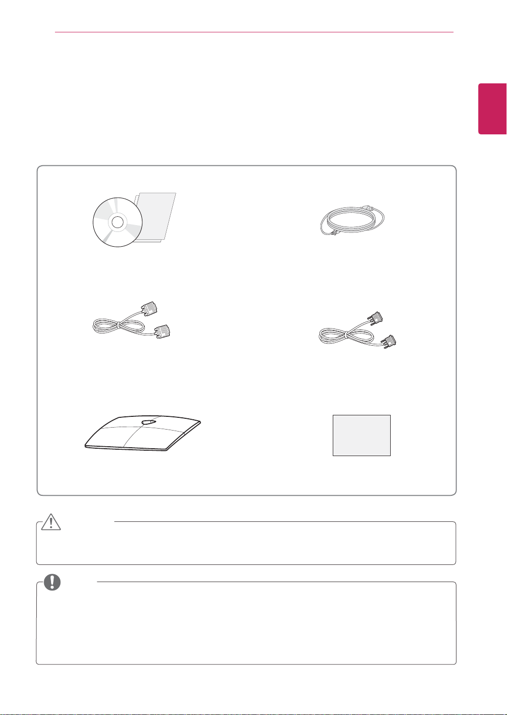
Unpacking
Check your product box for the following items. If there are any missing accessories, contact the local
dealer where you purchased your product. The illustrations in this manual may differ from the actual product
and accessories.
CD(Owner's Manual) /
Card
D-SUB Cable
(This signal cable may be attached
to this product before shipping out.)
(This cable is not included in all
Power Cord
DVI-D Cable
countries.)
ENGLISH
ENG
Stand Base
Display Quality Assurance Report
CAUTION
Do not use any unapproved accessories to ensure the safety and product life span.
Any damages or injuries by using unapproved accessories are not covered by the warranty.
NOTE
The accessories supplied with your product may vary depending on the model.
Product specifications or contents in this manual may be changed without prior notice due to upgrade
of product functions.
User must use shielded signal interface cables (D-sub 15 pin cable, DVI-D cable) with ferrite cores
(core in the connector) to maintain standard compliance for the product。
ENGLISH
ENG
ASSEMBLING AND PREPARING
4
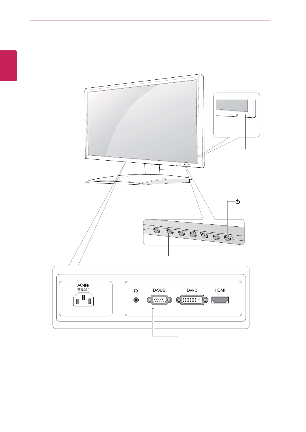
Parts and buttons
Power Indicator
Lighting On: Turned on
Lighting Off: Turned off
(Power Button)
Button (See p.13)
Connection panel (See p.10)
ASSEMBLING AND PREPARING
Button Description
MENU Accesses the main menus.(See p.13)
OSD LOCKED/
UNLOCKED
MODE Use this button to enter USER, MOVIE,TEXT,PHOTO,sRGB menus.(See p.18)
DUAL
AUTO When adjusting your display settings, always press the AUTO button on the MONITOR
INPUT You can choose the input signal.
EXIT Exit the OSD(On Screen Display).
(Power Button)
Use this button to enter DUAL MONITOR and DUAL WEB menus.(See p.19)
SETUP OSD. (Only supported in Analog Mode)
The best display mode 1920 x 1080
• When two input signals are connected, you can select the input signal (D-SUB/DVI/
HDMI) you want.
• When only one signal is connected, it is automatically detected. The default setting is
D-SUB.
Turns the power on or off.
Power Indicator The power indicator stays blue if the display is running
This function allows you to lock the current control settings, so
that they cannot be inadvertently changed.
Press and hold the MENU button for several seconds.
The message "OSD LOCKED" should appear
You can unlock the OSD controls at any time by pushing
the MENU button for several seconds. The message "OSD
UNLOCKED" should appear.
properly (On Mode). If the display is in Sleep Mode, the power
indicator blinks blue.
.
5
ENGLISH
ENG
ASSEMBLING AND PREPARING
Stand Base
1
Stand Base
6
ENGLISH
ENG
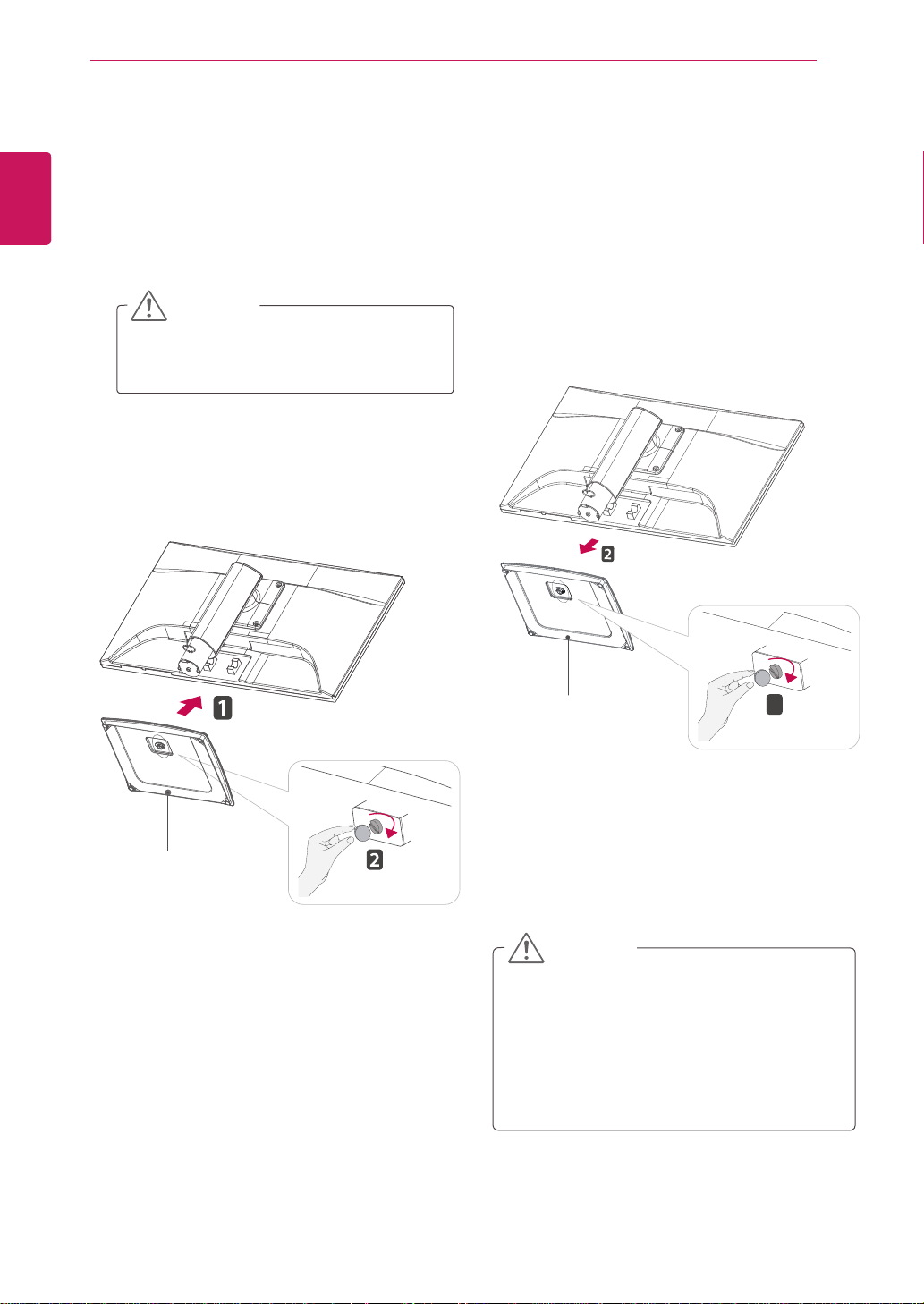
Setting up the Monitor set
Attaching the Stand Base
Place the Monitor set with the screen side
1
down on a flat and cushioned surface.
CAUTION
Lay a foam mat or soft protective cloth
on the surface to protect the screen from
damage.
Attach the Stand Base and then tighten the
2
screw to the right with a Coin.
Detaching the Stand Base
Place the Monitor set with the screen side
1
down on a flat and cushioned surface.
Turn the screw to the left, and then pull out the
2
Stand Base from the Stand Body.
CAUTION
This illustration depicts the general model of
y
connection. Your monitor may differ from the
items shown in the picture.
Do not carry the product upside down holding
y
only the stand base. The product may fall
and get damaged or injure your foot.
ASSEMBLING AND PREPARING
* Please be sure to
remove the Locking
pin to adjust the height.
5 - 51
130.0 mm
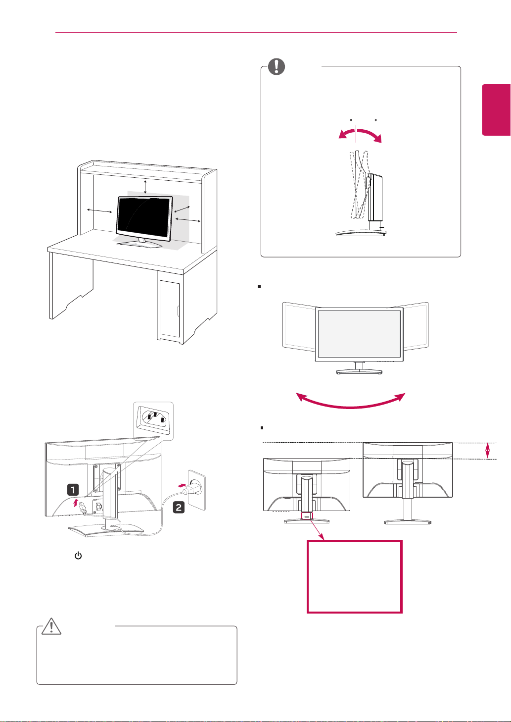
7
Mounting on a table
Lift and tilt the Monitor set into its upright
1
position on a table.
Leave a 10 cm (minimum) space from the wall
for proper ventilation.
10 cm
10 cm
10 cm
10 cm
NOTE
Tilt from +15 to -5 degrees up or down to adjust
the angle of the Monitor set to suit your view.
Front Rear
Swivel Range : - 45˚(+/- 2°)
ENGLISH
ENG
Connect the Power Cord to a wall outlet.
2
Press (Power) button on the front switch
3
panel to turn the power on.
CAUTION
Unplug the power cord before moving the
Monitor to another location. Otherwise electric
shock may occur.
45˚(+/- 2°)
Height Range : maximum 5.12 inches (130.0 mm)
ASSEMBLING AND PREPARING
8
ENGLISH
ENG
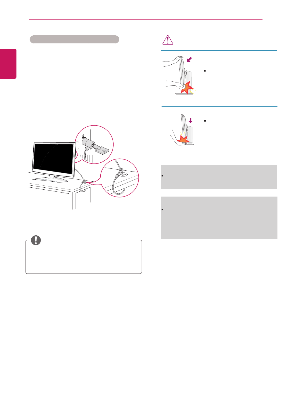
Using the Kensington security system
The Kensington security system connector is
located at the back of the Monitor set. For more
information of installation and using, refer to the
manual supplied with the Kensington security
system or visit
Connect the Kensington security system cable
between the Monitor set and a table.
http://www.kensington.com
.
NOTE
WARNING
When adjusting the angle of the
screen, do not put your finger(s)
in between the head of the monitor and the stand body. You
can hurt your finger(s).
When adjusting the height of the
screen, do not put your finger(s)
in between the head of the monitor and the stand base. You
can hurt your finger(s).
WARNING
You do not need to replace the Locking pin after it
is removed, to adjust its height.
ERGONOMIC
It is recommended that in order to maintain an erg-
onomic and comfortable viewing position, the forw-
ard tilt angle of the monitor should not exceed 5
degrees.
The Kensington security system is optional.
You can obtain it from most electronics stores.
 Loading...