

LG ID90c Service Manual

SERVICE MANUAL
CDMA PORTABLE CELLULAR PHONE
LG-ID90c
Z3X-BOX.COM

LG-ID90c
General Introduction
Table of Contents
CHAPTER 1. System Introduction
1. System Introduction ......................................................................................................................
2. Features and Advantages of CDMA Mobile Phone........................................................................
3. Structure and Functions of CDMA Mobile Phone...........................................................................
4. Specification ..................................................................................................................................
CHAPTER 2. NAM Input Method(Inputting of telephone numbers included)
1. Telephone Number and NAM Programming Method ....................................................................
CHAPTER 3. Circuit Description
1. RF Transmit/Receive Part .............................................................................................................
2. Digital/Voice Processing Part ........................................................................................................
CHAPTER 4. Trouble Shooting
CHAPTER 5. Safety
CHAPTER 6. Glossary
Z3X-BOX.COM

LG-ID90C
General Introduction
The LG-UD90C cellular phone functions as digital cellular phone worked in CDMA (Code Division
Multiple Access) mode.
CDMA mode applies the DSSS (Direct Sequence Spread Spectrum) technique that has been used in
military. This technique enables to share one frequency channel with many users in the same specific
area. As a result, that it increases the capacity 10 times more compared with that in the analog mode
(AMPS) currently used.
Soft/Softer Handoff, Hard Handoff, and Dynamic RF power Control technologies are combined into
this phone to reduce the call being interrupted in a middle of talking over phone.
CDMA digital cellular network consists of MSC (Mobile Switching Office), BSC (Base Station
Controller), BTS (Base station Transmission System), and MS (Mobile Station). Communication
between MS and BTS is designed to meet the specification of CDMA2000 1X (Common Air Interface).
MS meets the specifications of the below :
CDMA Standard Designator Description
Basic air interface
Network
Service
Performance
TIA/EIA/IS-95-A/B/C
ANSI J-STD-008
TIA/EIA/IS-634
TIA/EIA/IS/651
TIA/EIA/IS-41-C
TIA/EIA/IS-124
TIA/EIA/IS-96-B
TIA/EIA/IS-99
TIA/EIA/IS-637
TIA/EIA/IS-657
TIA/EIA/IS-97
Z3X-BOX.COM
TIA/EIA/IS-98 ANSI
J-STD-018 ANSI
J-STD-019
Protocol between MS and BTS for Cellular &
AMPS Protocol between MS and BTS for PCS
MAS-BS
PCSC-RS
Intersystem operations
Nom-signaling data comm.
Speech CODEC
Assign data and fax
Short message service
Packet data
Cellular base station
Cellular mobile station
PCS personal station
PCS base station
TIA/EIA/IS-125
3
Speech CODEC

LG-ID90C
CHAPTER 1. System Introduction
1. System Introduction
1.1 CDMA Abstract
The cellular system has a channel hand-off function that is used for collecting the information on the
locations and movements of radio mobile telephones from the cell site by automatically controlling
several cell site through the setup of data transmission routes and thus, enabling one switching
system to carry out the automatic remote adjustment. This is to maintain continuously the call state
through the automatic location confirmation and automatic radio channel conversion when the busy
subscriber moves from the service area of one cell site to that of another by using automatic location
confirmation and automatic radio channel conversion functions. The call state can be maintained
continuously by the information exchange between switching systems when the busy subscriber
moves from one cellular system area to the other cellular system area.
In the cellular system, the cell site is a small-sized low output type and utilizes a frequency allocation
system that considers mutual interference, in an effort to enable the re-use of corresponding
frequency from a cell site separated more than a certain distance. The analog cellular systems are
classified further into an AMPS system, E-AMPS System, NMT system, ETACS system, and JTACS
system depending on technologies used.
Unlike the Time Division Multiple Access (TDMA) or the Frequency Division Multiple Access (FDMA)
used in the band limited environment, the Code Division Multiple Access(CDMA) system which is one
of digital cellular systems is a multi-access technology under the interference limited environment. It
can process more number of subscribers compared to other systems (TDMA system has the
processing capacity three times greater than the existing FDMA system whereas CDMA system,
about 12~15 times of that of the existing system).
Z3X-BOX.COM
CDMA system can be explained as follows: TDMA or SDMA can be used to enable each person to
talk alternately or provide a separate room for each person when two persons desire to talk with each
other at the same time, whereas FDMA can be used to enable one person to talk in soprano, whereas
the other in bass (one of the two talkers can carry out synchronization for hearing in case there is a
bandpass filter function in the area of the hearer).
4

LG-ID90C
Another method available is to make two persons to sing in different languages at the same time,
space, and frequency when wishing to let the audience hear the singing without being confused. This
is the characteristics of CDMA.
On the other hand, when employing the CDMA technology, each signal has a different
pseudo-random binary sequence used to spread the spectrum of carrier. A great number of CDMA
signals share the same frequency spectrum. In the perspective of frequency area or time area, several
CDMA signals are overlapped. Among these types of signals, only desired signal energy is selected
and received through the use of pre-determined binary sequence; desired signals can be separated
and then, received with the correlator used for recovering the spectrum into its original state. At this
time, the spectrums of other signals that have different codes are not recovered into its original state
and instead, processed as noise and appears as the self-interference of the system.
Z3X-BOX.COM
5

LG-ID90C
2. Features and Advantages of CDMA Mobile Phone
2.1 Various Types of Diversities
When employing the narrow band modulation (30kHz band) that is the same as the analog FM
modulation system used in the existing cellular system, the multi-paths of radio waves create a
serious fading. However, in the CDMA broadband modulation(1.25MHz band), three types of
diversities (time, frequency, and space) are used to reduce serious fading problems generated from
radio channels in order to obtain high-quality calls.
Time diversity can be obtained through the use of code interleaving and error correction code
whereas frequency diversity can be obtained by spreading signal energy to wider frequency band. The
fading related to normal frequency can affect the normal 200~300kHz among signal bands and
accordingly, serious affect can be avoided. Moreover, space diversity (also called path diversity) can
be realized with the following three types of methods.
First, it can be obtained by the duplication of cell site receive antenna. Second, it can be obtained
through the use of multi-signal processing device that receives a transmit signal having each different
transmission delay time and then, combines them. Third, it can be obtained through the multiple cell
site connection (Soft Handoff) that connects the mobile station and more than two cell sites at the
same time.
2.2 Power Control
The CDMA system utilizes the forward (from a base station to mobile stations) and backward (from
the mobile station to the base station) power control in order to increase the call processing capacity
and obtain high-quality calls. In case the originating signals of mobile stations are received by the cell
site in the minimum call quality level (signal to interference) through the use of transmit power control
on all the mobile stations, the system capacity can be maximized.
If the signal of mobile station is received too strong, the performance of that mobile station is improved.
However, because of this, the interference on other mobile stations using the same channel is
Z3X-BOX.COM
increased and accordingly, the call quality of other subscribers is reduced unless the maximum
accommodation capacity is reduced.
In the CDMA system, forward power control, backward open loop power control, and closed loop
power control methods are used. The forward power control is carried out in the cell site to reduce the
transmit power on mobile stations less affected by the multi-path fading and shadow phenomenon and
the interference of other cell sites when the mobile station is not engaged in the call or is relatively
nearer to the corresponding cell site. This is also used to provide additional power to mobile stations
having high call error rates, located in bad reception areas or far away from the cell site.
6

LG-ID90C
The backward open loop power control is carried out in a corresponding mobile station; the mobile
station measures power received from the cell site and then, reversely increases/decreases transmit
power in order to compensate channel changes caused by the forward link path loss and terrain
characteristics in relation to the mobile station in the cell site. By doing so, all the mobile office
transmit signals in the cells are received by the cell site in the same strength.
Moreover, the backward closed loop power control used by the mobile station to control power with
the commands issued out by the cell site. The cell site receives the signal of each corresponding
mobile station and compares this with the pre-set threshold value and then, issues out power
increase/decrease commands to the corresponding mobile station every 1.25 msec (800 times per
second).
By doing so, the gain tolerance and the different radio propagation loss on the forward/backward link
are complemented.
2.3 Voice Encoder and Variable Data Speed
The bi-directional voice service having variable data speed provides voice communication which
employs voice encoder algorithm having power variable data rate between the mobile telephone cell
site and mobile station. On the other hand, the transmit voice encoder performs voice sampling and
then, creates encoded voice packets to be sent out to the receive voice encoder, whereas the receive
voice encoder demodulates the received voice packets into voice samples.
One of the two voice encoders described in the above is selected for use depending on inputted
automatic conditions and message/data; both of them utilize four-stage frames of 9600, 4800, 2400,
and 1200 bits per second. In addition, this type of variable voice encoder utilizes adaptive threshold
values when selecting required data rate. It is adjusted in accordance with the size of background
noise and the data rate is increased to high rate only when the voice of caller is inputted.
Therefore, background noise is suppressed and high-quality voice transmission is possible under the
environment experiencing serious noise. In addition, in case the caller does not talk, data transmission
rate is reduced so that the transmission is carried out in low energy. This will reduce the interference
Z3X-BOX.COM
on other CDMA signals and as a result, improve system performance (capacity, increased by about
two times).
2.4 Protecting Call Confidentiality
CDMA signals have the function of effectively protecting call confidentiality by spreading and
interleaving call information in broad bandwidth. This makes the unauthorized use of crosstalk, search
receiver, and radio very hard substantially. Also included is the encryption function on various
authentication and calls specified in IS-95 for the double protection of call confidentiality.
7

LG-ID90C
2.5 Soft Handoff
During the soft hand, the cell site already in the busy state and the cell site to be engaged in the call
later participate in the call conversion. The call conversion is carried out through the original call
connection cell site, both cell sites, and then, new cell site. This method can minimize call
disconnection and prevent the user from detecting the hand-off.
2.6 Frequency Re-Use and Sector Segmentation
Unlike the existing analog cellular system, the CDMA system can reuse the same frequency at the
adjacent cell and accordingly, there is no need to prepare a separate frequency plan. Total
interference generated on mobile station signals received from the cell site is the sum of interference
generated from other mobile stations in the same cell site and interference generated from the mobile
station of adjacent cell site. That is, each mobile station signal generates interference in relation to the
signals of all the other mobile signals.
Total interference from all the adjacent cell sites is the ratio of interference from all the cell sites
versus total interference from other mobile stations in the same cell site (about 65%). In the case of
directional cell site, one cell normally uses a 120°sector antenna in order to divide the sector into three.
In this case, each antenna is used only for 1/3 of mobile stations in the cell site and accordingly,
interference is reduced by 1/3 on the average and the capacity that can be supported by the entire
system is increased by three times.
2.7 Soft Capacity
The subscriber capacity of CDMA system is flexible depending on the relation between the number of
users and service classes. For example, the system operator can increase the number of channels
available for use during the busy hour despite the drop in call quality. This type of function requires
40% of normal call channels in the standby mode during the handoff support, in an effort to avoid call
disconnection resulting from the lack of channels.
In addition, in the CDMA system, services and service charges are classified further into different
Z3X-BOX.COM
classes so that more transmit power can be allocated to high class service users for easier call set-up;
they can also be given higher priority of using hand-off function than the general users.
8

LG-ID90C
3. Structure and Functions of CDMA Mobile Phone
The mobile station of CDMA system is made up of a radio frequency part and logic/control (digital)
part. The mobile station is fully compatible with the existing analog FM system. The mobile station
antenna is connected with the transmitter/receiver via a duplexer filter so that it can carry out the
transmit/receive function at the same time.
The transmit frequency is the 25MHz band of 824~849MHz, whereas the receive frequency is the
25MHz band of 869~894MHz. The transmit/receive frequency is separated by 45MHz. The RF signal
from the antenna is converted into Baseband signal by direct-conversion(RadioOne chip) frequency
down converter and then, converted into digital signals via an analog-to-digital converters(ADC) and
then, sent out respectively to 5 correlators in each CDMA de-modulator. Of these, one is called a
searcher whereas the remaining 4 are called data receiver(finger). Digitalized IF signals include a
great number of call signals that have been sent out by the adjacent cells. These signals are detected
with pseudo-noise sequence (PN Sequence). Signal to interference ratio (C/I) on signals that match
the desired PN sequence are increased through this type of correlation detection process. Then, other
signals obtain processing gain by not increasing the ratio. The carrier wave of pilot channel from the
cell site most adjacently located is demodulated in order to obtain the sequence of encoded data
symbols.
During the operation with one cell site, the searcher searches out multi-paths in accordance with
terrain and building reflections. On three data receivers, the most powerful four paths are allocated for
the parallel tracing and receiving. Fading resistance can be improved a great deal by obtaining the
diversity combined output for de-modulation. Moreover, the searcher can be used to determine the
most powerful path from the cell sites even during the soft handoff during the two cell sites. Moreover,
four data receivers are allocated in order to carry out the de-modulation of these paths. Data output
that has been demodulated change the data string in the combined data row as in the case of original
signals(deinterleaving), and then, are de-modulated by the forward error correction decoder which
uses the Viterbi algorithm.
On the other hand, mobile station user information sent out from the mobile station to the cell site pass
through the digital voice encoder via a mike. Then, they are encoded and forward errors are corrected
through the use of convolution encoder. Then, the order of code rows is changed in accordance with a
certain regulation in order to remove any errors in the interleaver. Symbols made through the above
Z3X-BOX.COM
process are spread after being loaded onto PN carrier waves. At this time, PN sequence is selected
by each address designated in each call.
Signals that have been code spread as above are digital modulated (QPSK) and then, power
controlled at the automatic gain control amplifier (AGC Amp). Then, they are converted into RF band
by the frequency synthesizer synchronizing these signals to proper output frequencies. Transmit
signals obtained pass through the duplexer filter and then, are sent out to the cell site via the antenna.
9
LG-ID90C
4. Specification
4.1 General Specification
4.1.1 Transmit/Receive Frequency Interval
1) CDMA: 45MHz
4.1.2 Number of Channels (Channel Bandwidth)
1) CDMA : 20 CH (BW: 1.23MHz)
4.1.3 Operating Voltage : DC 3.7V
4.1.4 Battery Power Consumption : DC 3.7V
SLEEP IDLE MAX POWER
CDMA 1.5 mA 160 mA 650 mA (24 dBm)
4.1.5 Operating Temperature : -30° ~ +60°
4.1.6 Frequency Stability
1) CDMA : ±0.5PPM
4.1.7 Antenna : Intenna Type, 50 Ω
4.1.8 Size and Weight
1) Size : 48 X 98 X 15.2 mm
2) Weight : 85g
4.1.9 Channel Spacing
Z3X-BOX.COM
1) CDMA : 1.25MHz
4.1.10 Battery Type, Capacity and Orerating Time.
Unit = Hours, Minutes
Type Standard (800mAh)
Stand-By Time CDMA 100~130 Hrs (SCI=1)
Talk Time CDMA 130 Min
10

LG-ID90C
4.2 Receive Specification
4.2.1 Frequency Range
CDMA : 869.820 MHz ~ 893.190 MHz
4.2.2 Local Oscillating Frequency Range
1664.7MHz ~1787.94MHz
4.2.3 Zero Intermediate Frequency
4.2.4 Sensitivity
CDMA : -104dBm (C/N 12dB or more)
4.2.5 Selectivity
CDMA : 3dB C/N Degration (With Fch±1.25 kHz : -30dBm)
4.2.6 Spurious Wave Suppression : Maximum of -80dB
4.2.7 CDMA Input Signal Range
Dynamic area of more than -104~ -25 dB : 79dB at the 1.23MHz band.
Z3X-BOX.COM
11

LG-ID90C
4.3 Transmit Specification
4.3.1 Frequency Range
CDMA : 824.820MHz ~ 848.190MHz
4.3.2 Local Oscillating Frequency Range
1649.64MHz ~1696.38MHz
4.3.3 Zero Intermediate Frequency
4.3.4 Output Power
CDMA : 0.32W
4.3.5 Interference Rejection
1) Single Tone : -30dBm at 900 kHz
2) Two Tone : -43dBm at 900 kHz & 1700kHz
-32dBm at 900 kHz & 1700kHz
-21dBm at 900 kHz & 1700kHz
4.3.6 CDMA TX Frequency Deviation
1) CDMA : ±300Hz or less
4.3.7 CDMA TX Conducted Spurious Emissions
1) 900kHz : - 42 dBc/30kHz below
2) 1.98MHz : - 54 dBc/30kHz below
4.3.8 CDMA Minimum TX Power Control : - 50dBm below
Z3X-BOX.COM
12
LG-ID90C
4.4 MS (Mobile Station) Transmitter Frequency
FA NO.
10 363 835.890 MHz 20 779 848.370 MHz
CH.NO
.
1 1011 824.640 MHz 11 404 837.120 MHz
2 29 825.870 MHz 12 445 838.350 MHz
3 70 827.100 MHz 13 486 839.580 MHz
4 111 828.330 MHz 14 527 840.810 MHz
5 152 829.560 MHz 15 568 842.04 MHz
6 193 830.790 MHz 16 609 843.270 MHz
7 234 832.020 MHz 17 650 844.500 MHz
8 275 833.250 MHz 18 697 845.910 MHz
9 316 834.480 MHz 19 738 847.140 MHz
CENTER FREQUENCY FA NO.
MS (Mobile Station) Receiver Frequency
4.5
FA NO.
CH.NO
.
1 1011 869.640 MHz 11 404 882.120 MHz
CENTER FREQUENCY FA NO.
CH.NO
.
CH.NO
.
CENTER FREQUENCY
CENTER FREQUENCY
2 29 870.870 MHz 12 445 883.350 MHz
3 70 872.100 MHz 13 486 884.580 MHz
4 111 873.330 MHz 14 527 885.810 MHz
5 152 874.560 MHz 15 568 887.04 MHz
6 193 875.790 MHz 16 609 888.270 MHz
7 234 877.020 MHz 17 650 889.500 MHz
8 275 878.250 MHz 18 697 890.910 MHz
9 316 879.480 MHz 19 738 892.140 MHz
10 363 880.890 MHz 20 779 893.370 MHz
Z3X-BOX.COM
13

LG-ID90C
(Inp
)
CHAPTER 2. NAM Input Method
(Inputting of MIN included)
1. HOW TO POWER UP
2. You have to input correct PIN code[Default Code: 0000], then press [OK] key.
3. Handset start data loading process, and then searching signal.
1. Telephone Number and NAM Programming Method
Press ******159753
•
Then, the following Menu is appeared.
1. Press power key.
2. NAM Input Method
utting of telephone numbers included
1 : Service Program
2 : Test screen
3 : Test Call
4 : Vocoder Set
5 : Verify ADM
6 : Error Screen
7 : Del Error
8 : SMS MO
Press 1: Service Mode to program MIN and NAM.
•
1. ESN
2. MIN
3. Nam Name
4. Security Code
5. MCC
6. NMSID
7. IMSI_T MCC
8. IMSI_T NMSID
9. PRL Enabled
10. MDN
11. CDMA Home SID
12. CDMA Home NID
Press a number what you want to edit.
•
Press [edit] to edit, after input, press [OK] to save
•
To reset the handset, press [END]
•
Z3X-BOX.COM
13. CDMA Pri.chA
14. CDMA Sec.ChA
15. CDMA Pri.chB
16. CDMA Sec.chB
15. Lockout SID
16. Lcokout NID
17. Home SysReg
18. Forn SID Reg
19. Forn NID Reg
22. ACCOLC
23. Phone Model
24. Slot Cycle Index
14

LG-KG90C
CHAPTER 3. Circuit Description
1. RF Transmit/Receive Part
1.1 Overview
The Tx and Rx part employs the Direct-Conversion system. The Tx and Rx frequencies are
824.04~848.97 and 869.04~893.97. RF signals received through the antenna are seperated by the
duplexer.
RF Signal fed into the YGHF-D010A(RF onechip module). The RF signal is changed into baseband
signal directly. Then, this signal is changed into digital signal by the analog to digital converter (ADC,
A/D Converter), and the digital circuit part of the MSM(Mobile Station Modem) 6100 processes the
data from ADC. The digital processing part is a demodulator.
In the case of transmission, YGHF-D010A receives OQPSK-modulated anlaog signal from the
MSM6100.
The YGHF-D010A connects directly with MSM6100 using an analog baseband interface.
In YGHF-D010A, the baseband quadrature signals are upconverted to the Cellular frequency bands
and amplified in order to have enough power for radiation. Finally, the RF signal is sent out to the cell
site via the antenna.
1.2 Description of RF Part Circuit
1.2.1 RF onechip Module (
The RF SPM is a fully intergrated RF module for mobile handsets execpt V-TCXO. This module can
be operated in CDMA & GPS mode. This module adopted ZIF(Zero IF) chipsets that include the
VCO’s, PLLs, up/down mixers, LNA, base band LPF, and Transmitter AGC amplifier. Also additional
components are fully intergrated such as BPF, power amplifier, duplexer, swithchs. Receiver LNA
used operates 4-stepped gain control. IN addition the receiver can be controllable IP2 and automatic
DC-offset calibration. This module includes transmitter base band amplifier, up-converter, drive
amplifier. The transmitter power can be controllable greater than 85dB dynamic rages and operated
under 2.8V supply voltage except the power amplifier. The two types of filter is used for this module.
One is Tx/Rx BPFs made by CSP(Chip Scale Package) technoloty. The other is Saw Duplexer that
Z3X-BOX.COM
YGHF-D010A)
has high isolation and attenuation.
15

LG-KG90C
1.3 Description of Frequency Synthesizer Circuit
1.3.1 Temperature Compensated Crystal Oscillator (TCXO, X1100)
Operating temperature is -30~+85 °C. The receives frequency tuning signals called TRK_LO_ADJ
from MSM as 2.66V~2.94V DC via R and C filter in order to generate the reference frequency of 19.2
MHz and input it into the frequency synthesizer. Frequency stability depending on temperature is
2.0 ppm.
±
2. Digital/Voice Processing Part
2.1 Overview
The digital/voice processing part processes the user's commands and processes all the digital and
voice signal processing in order to operate in the phone. The digital/voice processing part is made up
of a keypad/LCD, receptacle part, voice processing part, mobile station modem part, memory part,
and power supply part.
2.2 Configuration
2.2.1 Keypad/LCD and Receptacle Part
This is used to transmit keypad signals to MSM6100. It is made up of a keypad backlight part that
illuminates the keypad, LCD part that displays the operation status onto the screen, and a receptacle
that receives and sends out voice and data with external sources.
2.2.2 Voice Processing Part
The voice processing part is made up of an audio codec used to convert MIC signals into digital voice
signals and digital voice signals into analog voice signals, amplifying part for amplifying the voice
signals and sending them to the ear piece, amplifying part that amplifies ringer signals coming out
from MSM6100, and amplifying part that amplifies signals coming out from MIC and transferring them
to the audio processor.
2.2.3 MSM6100 (Mobile Station Modem) Part
MSM is the core elements of CDMA terminal and carries out the functions of CPU, encoder,
interleaver, deinterleaver, Viterbi decoder, Mod/Demod, and vocoder.
Z3X-BOX.COM
16

LG-KG90C
2.2.4 Memory Part
The memory part is made up of a flash memory, SDRAM for storing data.
2.3 Circuit Description
2.3.1 Keypad/LCD and Receptacle Part
Once the keypad is pressed, the key signals are sent out to MSM6100 for processing. In addition,
when the key is pressed, the keypad/LCD lights up through the use of LEDs. The terminal status and
operation are displayed on the screen for the user with the characters and icons on the LCD.
Moreover, it exchanges audio signals and data with external sources through the receptacle, and then
receives power from the battery or external batteries.
2.3.2 Audio Processing Part
MIC signals are amplified through OP AMP, inputted into the audio codec(included in MSM6100) and
converted into digital signals. Oppositely, digital audio signals are converted into analog signals after
going through the audio codec. These signals are amplified at the audio amplifier and transmitted to
the ear-piece. The signals from MSM6100 activate the ringer by using signals generated in the timer
in MSM6100.
2.3.3 MSM Part
The MSM6100 chipset integrates functions that support both tri-mode CDMA/FM and cellular-only
handset operation. Subsystems within the MSM6100 baseband processor device include a CDMA
processor, digital FM (DFM) processor, QCT’s latest generation of DSP, the QDSP4000™ core, for
Z3X-BOX.COM
voice compression and applications support, PLL and an ARM® ARM926EEJ-S microprocessor. Also
integrated in the MSM6100 device are analog functions such as a wideband mono codec and analog
interfaces for the radioOne RF ASICs. Controllers for a universal serial bus (USB), device controller
for an R-UIM (CDMA SIM), GPIOs, and peripheral interfaces complete the system integration. And the
MSM6100 chipset and system software are designed to support IS95A/95B and Release 0 of
CDMA2000 standards.
In MSM, coded symbols are interleaved in order to cope with multi-path fading. Each data channel is
17

LG-KG90C
scrambled by the long code PN sequence of the user in order to ensure the confidentiality of calls.
Moreover, binary quadrature codes are used based on walsh functions in order to discern each
channel. Data created thus are 4-phase modulated by one pair of Pilot PN code and they are used to
create I and Q data.
When received, I and Q data are demodulated into symbols by the demodulator, and then
de-interleaved in reverse to the case of transmission. Then, the errors of data received from viterbi
decoder are detected and corrected. They are voice-decoded at the vocoder in order to output digital
voice data.
2.3.4 Memory Part
Memory part consists of 1 Gbits flash memory and 512 Mbits Static RAM. the Flash Memory part are
programs used for terminal operation. The programs can be changed through down loading after the
assembling of terminals. On the SRAM data generated during the terminal operation are stored
temporarily.
2.3.5 UIM Part
The MSM6100 is supports RUIM.
The UIM card contains the information of phone number, PIM data, SMS data, etc.
The whole circuits are designed to operate 3.00V UIM cards.
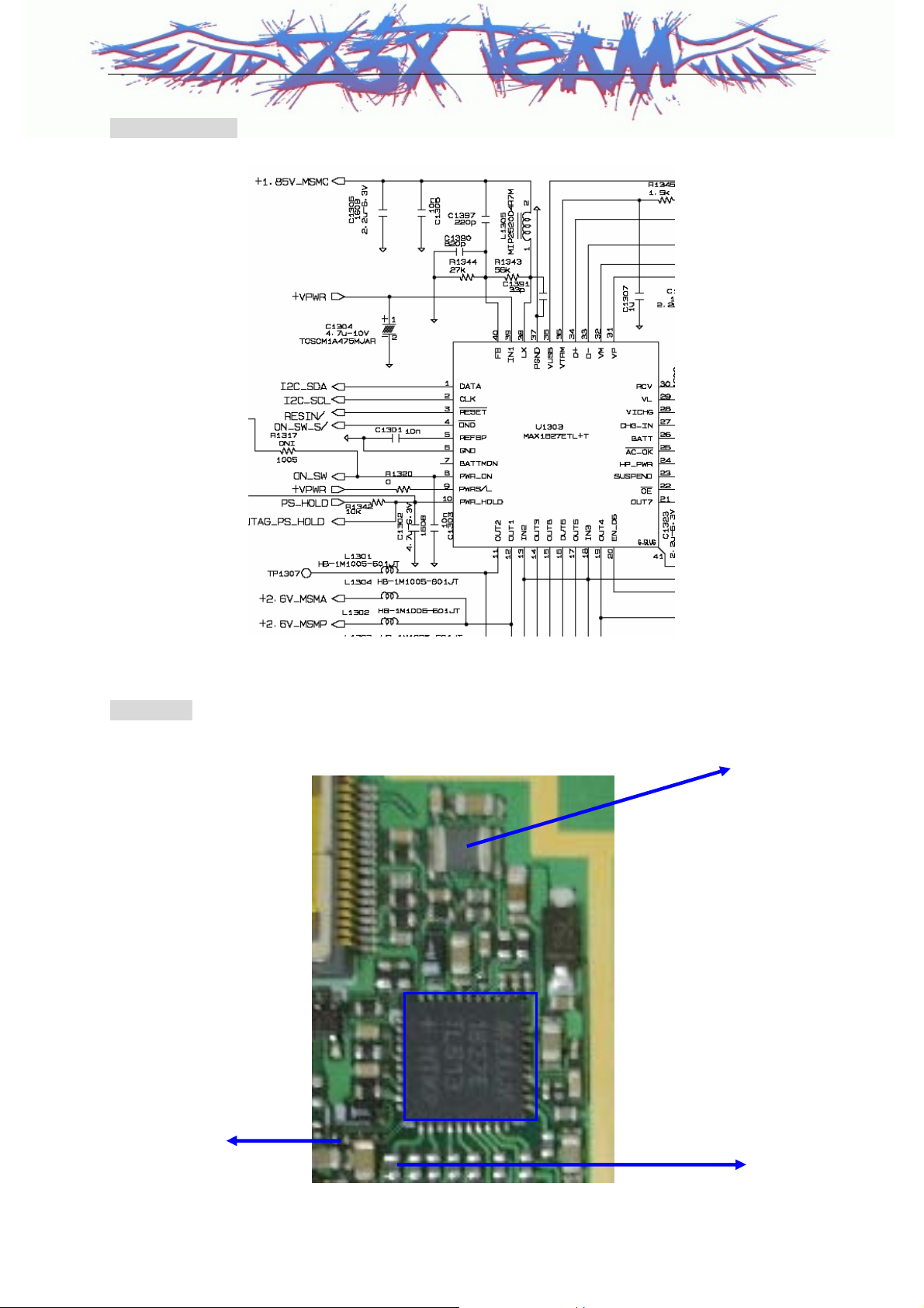
2.3.6 Power Supply Part
Turn On
When the battery voltage (2.7V ~ 5.5V) is fed and the PWR key of keypad is pressed,
PMIC(MAX1827) is activated by the PWR_ON_SW/ signal, and then the control signal PS_HOLD
signal is generated. And then, the regurator 1.85V_MSMC & 2.6V_MSMP, 2.6V_MSMA, are operated.
Operating
During the phone is on operating state,
PMIC(MAX1827) for MSM is always enable and gives the power MSM6100 and memory part
Z3X-BOX.COM
PMIC(MAX1827) for +3V_TX part is enabled on traffic state, and gives the power TX part devices.
LDO for +3V_RX part is enabled on idel state, and gives the power RX part devices.
Turn OFF
When the PWR key is pressed during a few seconds, PMIC(MAX1827) is turned on by
PWR_ON_SW/ and then, 'Low' is outputted on PS_HOLD. MSM6100 receives this signal and then,
recognizes that the POWER key has been pressed. During this time, MSM6100 outputs PS_HOLD as
low and turn off all devices
18

LG-KG90C
2.3.7 Logic Part
The Logic part consists of internal CPU of MSM6100, MCP(SRAM& FLASH MEMORY) .
The MSM6100 receives TCXO (=19.2MHz) and controls the phone in both CDMA and FM modes.
The major components are as follows:
CPU : ARM926EEJ-S microprocessor core
MEMORY :
FLASH Memory + SRAM : 1G bits(Flash) + 512M bits(SRAM)
•
CPU
ARM926EEJ-S 32-bit microprocessor is used and CPU controls all the circuitry. Some of the features
of the ARM microprocessor include a 3 stage pipelined RISC architecture, both 32-bit ARM and 16bit
THUMB instruction setsm, a 32-bit address bus, and a 32-bit internal data bus.
FLASH Memory
Flash Memory is used to store the program of the mobile station. Using the down-loading program, the
program can be changed even after the mobile station is fully assembled.
SRAM
SRAM is used to store the internal flag information, call processing data, and timer data.
KEYPAD
For key recognition, key matrix is setup using GPIO46,47,50,51,52,53,62,63 of output ports of MSM.
Backlight circuitry are included in the keypad for easy operation in the dark.
LCD MODULE
LCD module contains a controller which will display the information onto the LCD by 16-bit data from
the MSM6100
It is also supplied stable +2.6V_MSMP by PMIC(MAX1827) for fine view angle and LCD reflects to
improve the display efficiency. White LEDs are used to display LCD backlight.
Z3X-BOX.COM
19
LG-KG90C
CHAPTER 4. Trouble Shooting
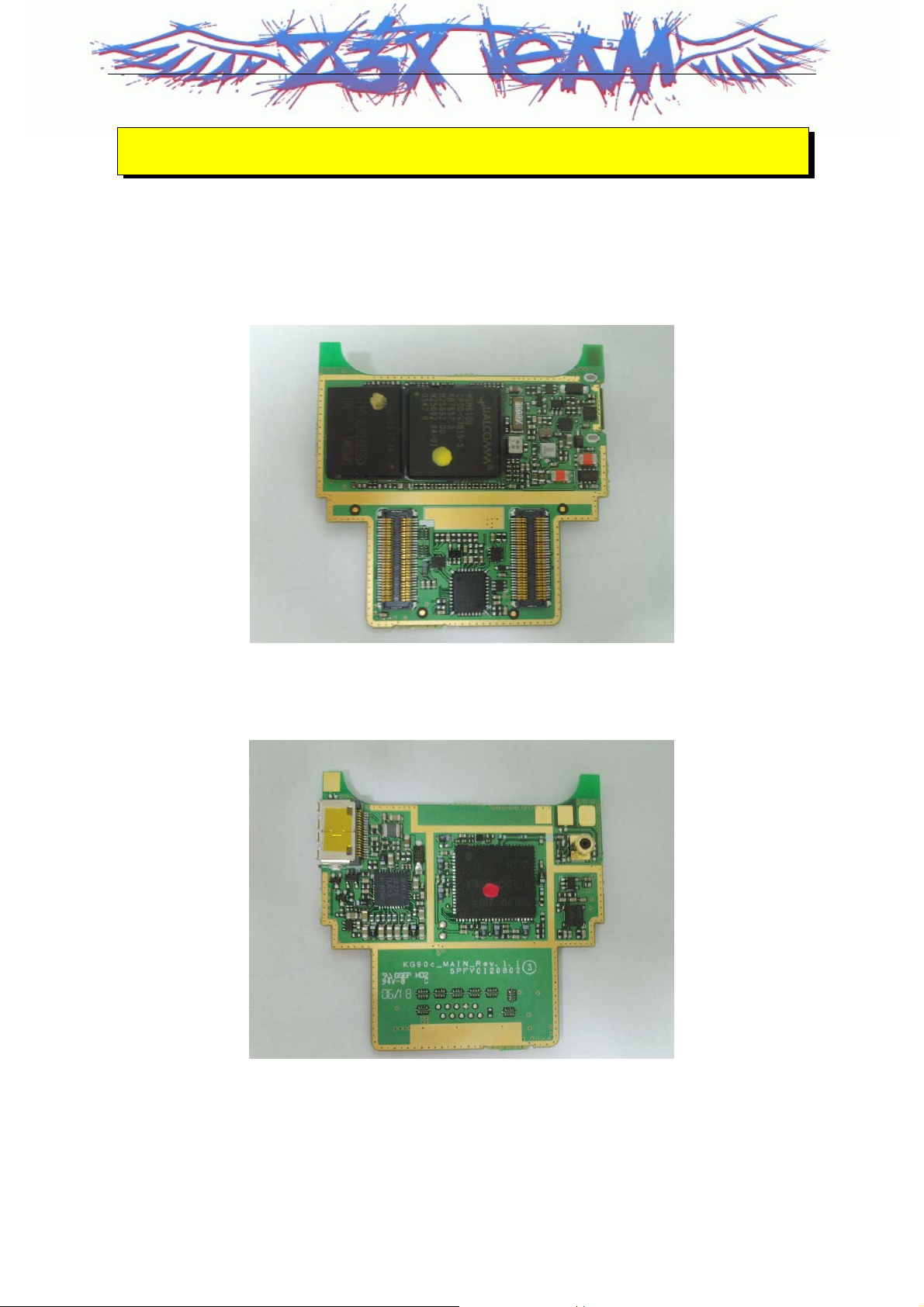
LG-UD90C MAIN TOP
LG-UD90C MAIN BOTTOM
Z3X-BOX.COM
20
LG-KG90C
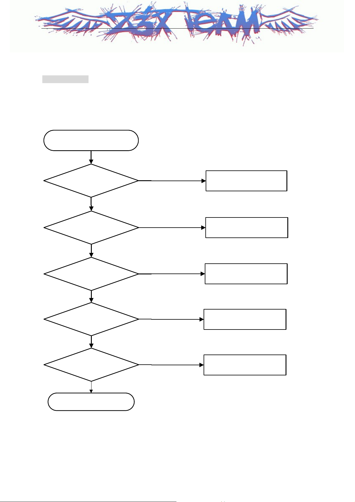
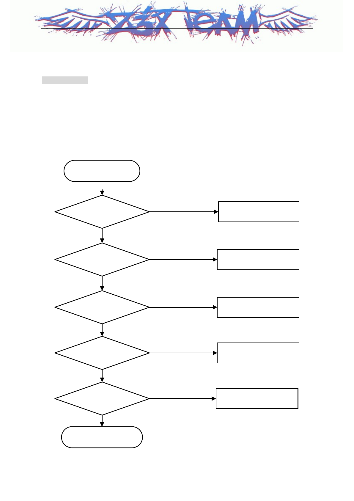
1. When power isn't "Turn On".
Checking Flow
- U1303 : MAX1827 (PMIC)
- U1201 : MSM6100
- X1100 : TG-5000(TCXO)
START
Supply Voltage 3.2 V~
4.2 V
Yes
Is U1303 No.10-pin
High(PS_Hold Check)
Yes
Is U1303 No.12-pin
2.6 V?
Yes
Is U1303 No.38-pin
1.85 V?
Yes
Z3X-BOX.COM
NO
NO
NO
NO
Rechange
Battery
Check U1201(MSM6100)
Change U1303(MAX1827)
Change U1303(MAX1827)
Is X1100 No.3-pin
19.2 MHz
Yes
Check U1201(MSM6100)
NO
Check X1100(TCXO)
21
LG-KG90C
Circuit Diagram
Test Point
1.85V_MSMC
Z3X-BOX.COM
U1303
PS_HOLD
2.6V_MSMP
22
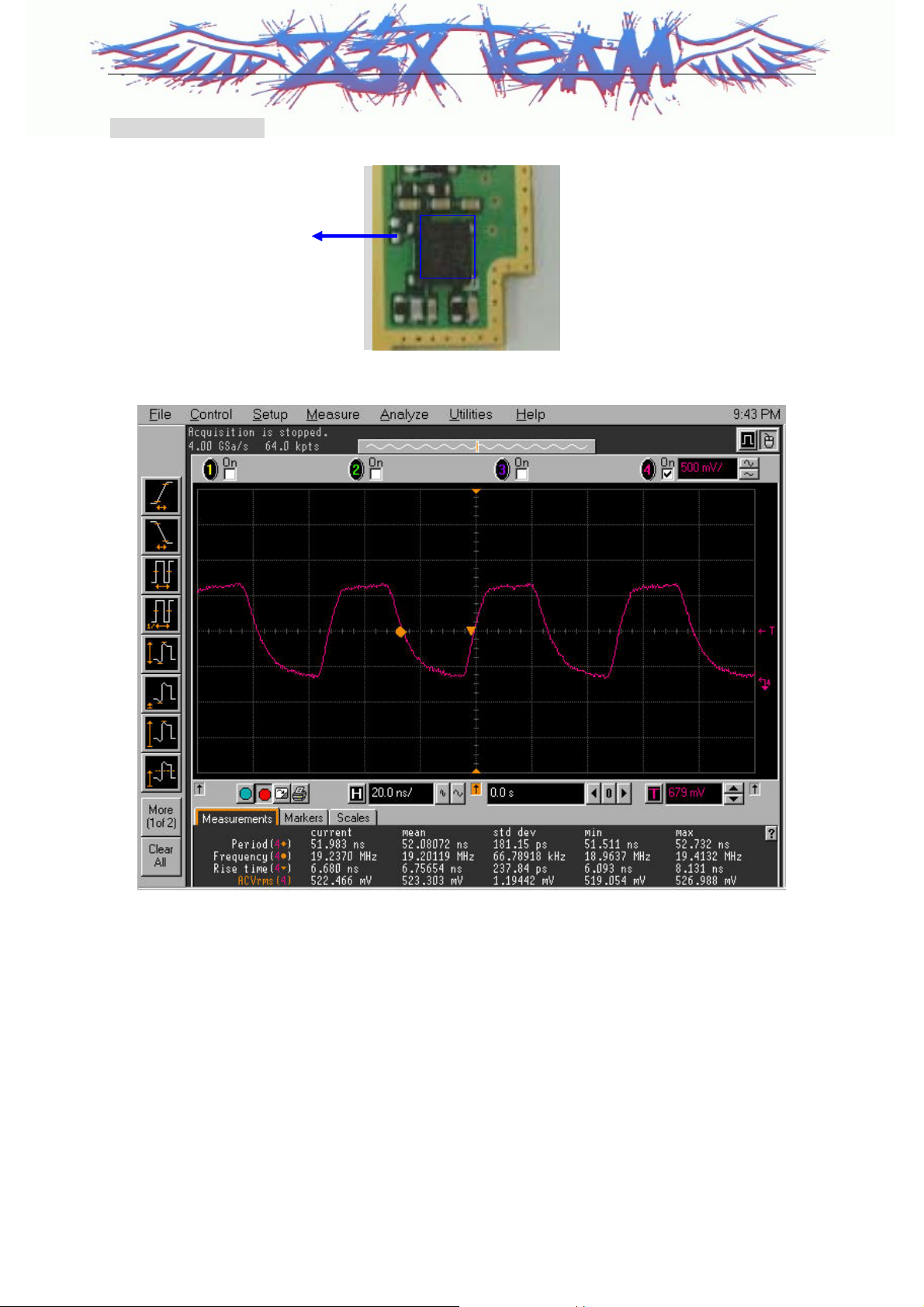
LG-KG90C
Waveform (TCXO)
TCXO_OUTPUT
X1100
Z3X-BOX.COM
23
LG-KG90C
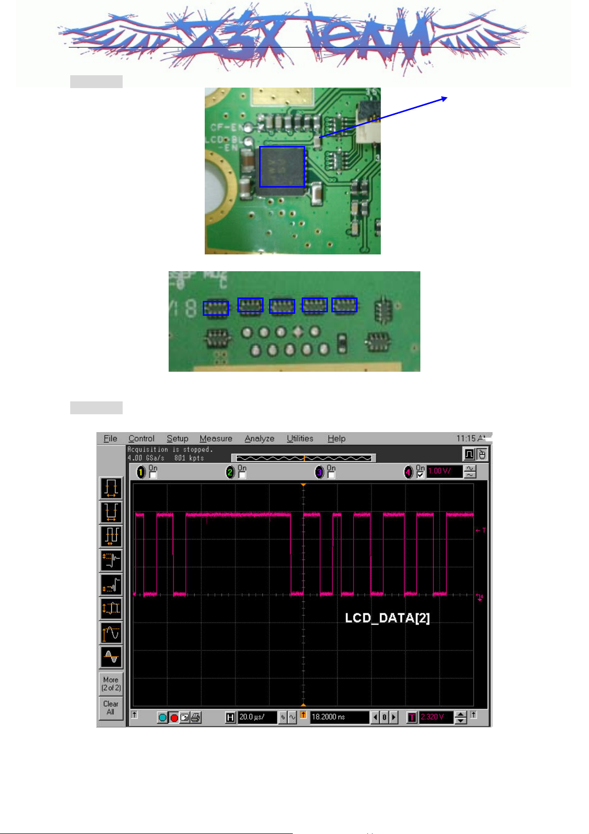
2. When LCD isn't displayed.
Checking Flow
- CON3000 : 70-pin Connector
- CON1501, CON1502 : 60-pin connector
- CON3102 : 35-pin connector
- F1501~1505 : EMI Filter
- U1201 : MSM6100
- U3100 : LED charge-pump
START
Supply Voltage,
Current OK ?
Yes
Check CON3102,
CON3000,CON1501,CON1
502 Connection
OK
Can you detect output
voltage on U3100 pin13
Yes
Z3X-BOX.COM
Are EMI Filters open?
No
NO
NG
NO
Yes
Check Power-on
Reconnect CON3000,
CON1501, CON1502,
CON3102
Change U3100
Resolder or change EMI
Filters
(F1501~F1505)
Is LCD data line OK?
No
Change U1201
Yes
Change Main LCD
24
LG-KG90C
Test Point
Vout_BL
Waveform
U3100
`
CON601 No 18 , 19 : 2.8V_L , 2.65V_MSMP
Z3X-BOX.COM
25
LG-KG90C
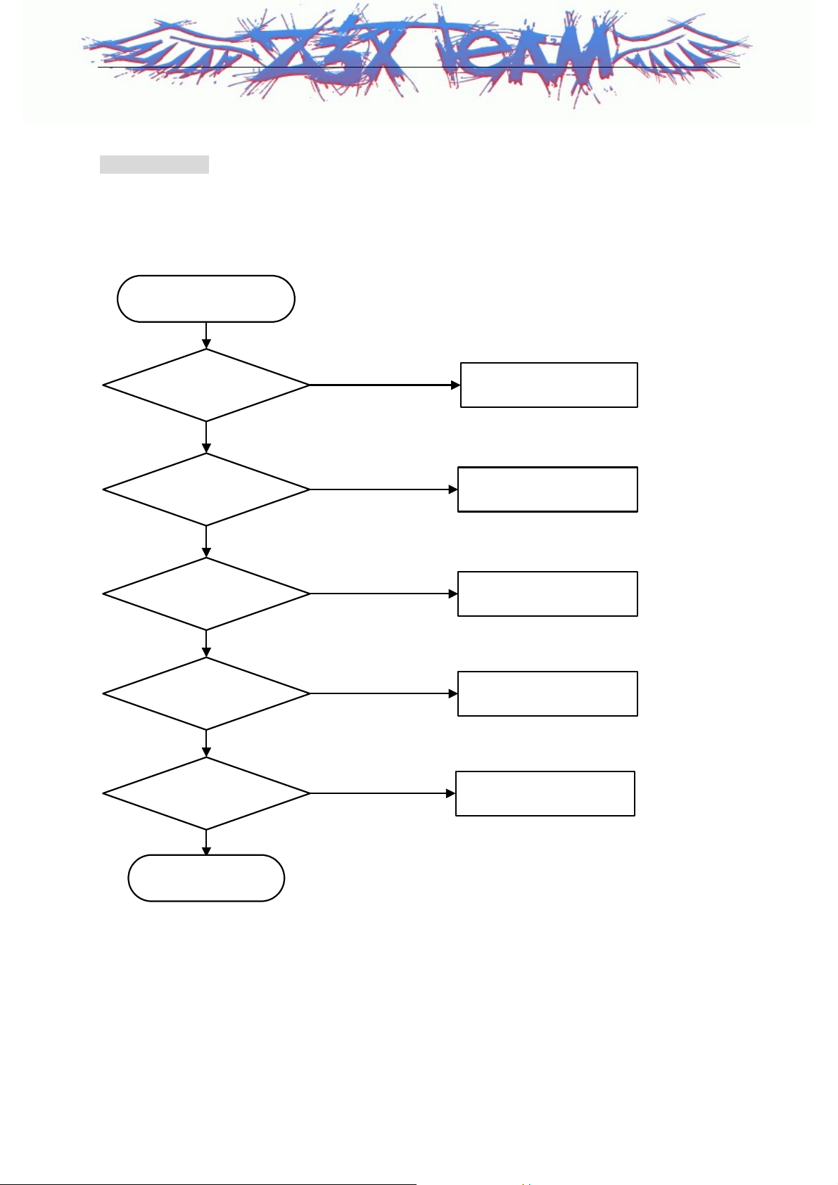
3. When Camera isn’t activated.
Checking Flow
START
- CON3100 : 24-pin Connector
- U3101, U3102, U3103 : LDO
- F3101, F3102 : EMI Filter
- X3100 : XTAL oscillator
Is CON3100 and FPCB
Connecting OK ?
Yes
When camera operates,
Is U3101, U3102, U3103
pin4 high?
Yes
When camera operates,
Does CLK signal detected on
X3100 pin3
Yes
Can you detect any data
signal from F3101, F3102 ?
Yes
Is LCD Module and Camera
connecting OK?
Z3X-BOX.COM
Yes
NO
NO
NO
NO
NO
Reconnecting
CON3100,FPCB
Check soldering of each
ICs, & change them
Check soldering of X3100,
& change it
Change,Check EMI Filter
Reconnecting LCD module
and Camera
Change Camera
Module
26
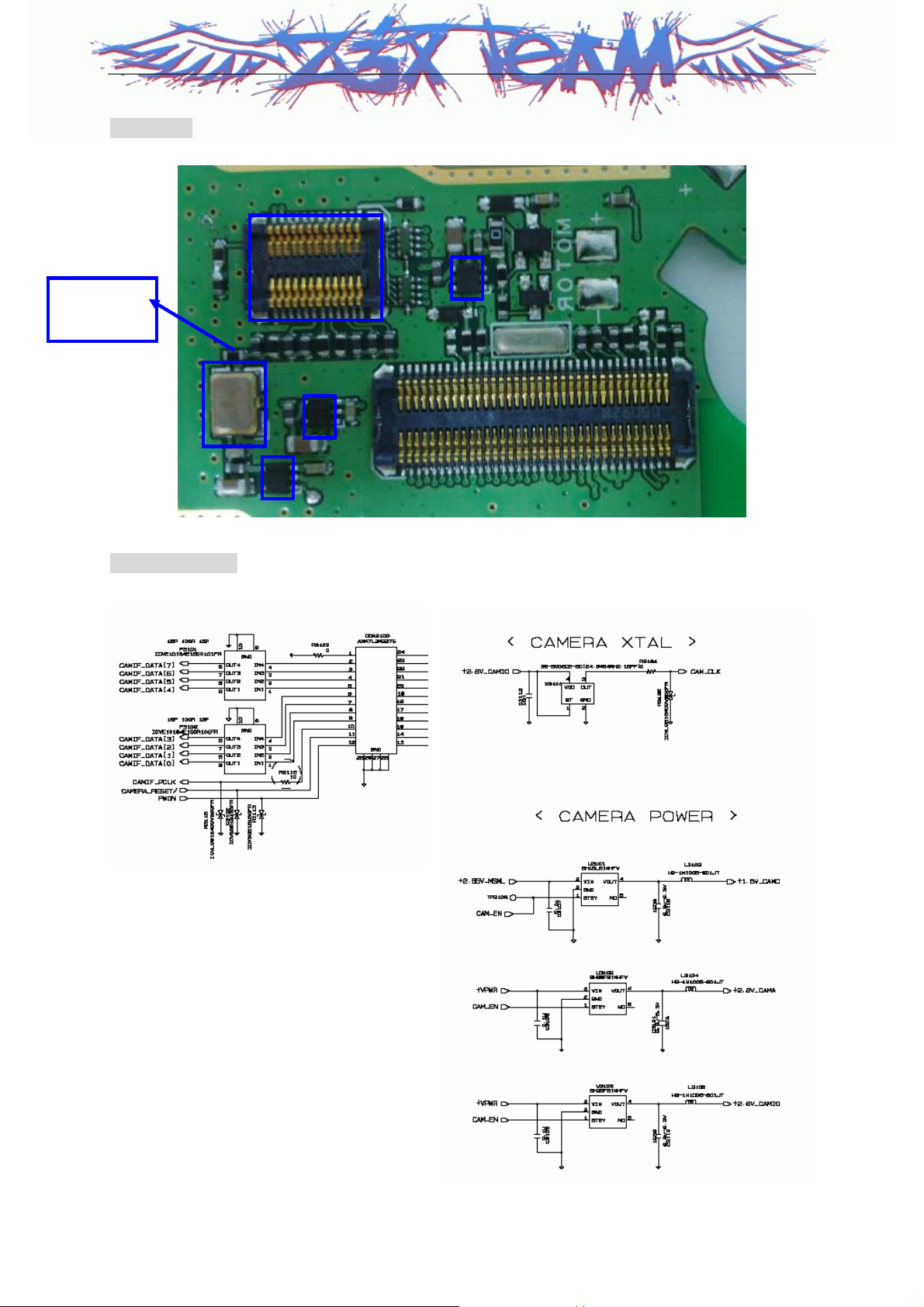
LG-KG90C
Test Point
X3100 pin3
CON3100
X3100
Circuit Diagram
Z3X-BOX.COM
27
 Loading...