

Page 1

Please read this manual carefully before operating your set and retain it for future
reference.
(Air-to-Water Heat Pump)
Original instruction
OWNER’S MANUAL
AIR-TO-WATER
HEAT PUMP
MFL69676301
Rev.01_071419
www.lg.com
Copyright © 2016 - 2019 LG Electronics Inc. All Rights Reserved.
ENGLISH
ITALIANO
ESPAÑOL FRANÇAIS
DEUTSCH
ΕΛΛΗΝΙΚΑ
ČEŠTINA
NEDERLANDS
POLSKI
LIMBA ROMÂNĂ
Page 2

Table of contents
TABLE OF CONTENTS
3 Safety Precautions
8 Instructions for the use of
owner’s manual
8 Important information
9 Glossary of used terms and conceptions
10 TERMOTRONIC controller
10 General
10 Controlling the device and heating system
11 Activating the device
11 Operation of the device
12 Standby
12 Operation HP STOP
12 Device HP STOP
13 Power outage
13 Display of the state of the device
14 Setting parameters
15 Setting the language
16 Quick settings
16 Setting the temperature of heating/cooling
18 Setting the temperature of heated water
21 Setting the temperature of DHW
22 Changing the operational mode -
winter/summer mode
24 Setting the cooling temperature
25 Switching on the additional heat source
26 Manual activation of the additional heat
source
46 Silent operation mode
47 User menus and parameters
47 Menu structure
54 Information display of
operation
55 Diagnostic displays
56 Display of the state of the device
58 Disruptions in operation,
alarms and troubleshooting
58 Troubleshooting
60 Maintenance and Service
60 Maintenance Activities
60 When the unit is not Operating
60 Call the service immediately in the following
situations
61 Settings of your heating
system at start-up
62 Search the Manual Using
Your Mobile
28 Advanced settings
29 Heating settings
37 Operating mode
37 Setting the cooling system
38 Schedules
42 Alternative source
43 Programme for drying screeds
44 Meters for operating hours
45 Setting the date, hour and day of the week
45 Remote turn on/off
46 PV signal
2 Air-to-Water Heat Pump
Page 3
Safety Precautions
ENGLISH
Safety Precautions
To prevent injury to the user or other people and property damage, the following instructions must be followed.
n Incorrect operation due to ignoring instruction will cause harm or damage. The seriousness is classified by
the following indications.
!
WARNING
!
CAUTION
This symbol indicates the possibility of death or serious injury.
This symbol indicates the possibility of injury or damage.
!
WARNING
• This appliance is not intended for use by persons (including children) with
reduced physical, sensory or mental capabilities, or lack of experience and
knowledge, unless they have been given supervision or instruction
concerning use of the appliance by a person responsible for their safety.
Children should be supervised to ensure that they do not play with the
appliance.
• This appliance can be used by children aged from 8 years and above and
persons with reduced physical, sensory or mental capabilities or lack of
experience and knowledge if they have been given supervision or
instruction concerning use of the appliance in a safe way and understand
the hazards involved. Children shall not play with the appliance. Cleaning
and user maintenance shall not be made by children without supervision.
• Always ground the product.
- There is a risk of electric shock.
• Do not use a defective or underrated circuit breaker. Use the correctly rated
breaker and fuse.
- There is risk of fire or electric shock.
• Do not use a multi outlet. Always use this appliance on a dedicated circuit
and breaker.
- There is risk of fire or electric shock.
• For electrical work, contact the dealer, seller, a qualified electrician, or an
Authorized Service Center. Do not disassemble or repair the product by
yourself.
- There is risk of fire or electric shock.
• Always ground the product as per the wiring diagram. Do not connect the
ground wire to gas or water pipes lightening rod or telephone ground wire.
- There is risk of fire or electric shock.
Owner’s Manual 3
Page 4

Safety Precautions
• Install the panel and the cover of control box securely.
- There is risk of fire or electric shock due to dust, water etc.
• Use the correctly rated breaker or fuse.
- There is risk of fire or electric shock.
• Do not modify or extend the power cable. If the power cable or cord has
scratches or skin peeled off or deteriorated then it must be replaced.
- There is risk of fire or electric shock.
• For installation, removal or reinstall , always contact the dealer or an
Authorized Service Center.
- There is risk of fire, electric shock, explosion, or injury.
• Do not install the product on a defective installation stand. Be sure that the
installation area does not deteriorate with age.
- It may cause product to fall.
• Never install the unit on a moving base or a place from where it can fall
down.
- The falling unit can cause damage or injury or even death of a person.
• When the product is soaked (flooded or submerged) in water, contact an
Authorized Service Center for repair before using it again.
- There is risk of fire or electric shock.
• Be sure to check the refrigerant to be used. Please read the label on the
product.
- Incorrect refrigerant can prevent the normal operation of the unit.
• Don't use a power cord, a plug or a loose socket which is damaged.
- Otherwise it may cause a fire or electrical shock.
• Do not touch , operate, or repair the product with wet hands.
- There is risk of electric shock or fire.
• Do not place a heater or other heating appliances near the power cable.
- There is risk of fire and electric shock.
• Do not allow water to run into electric parts. Install the unit away from water
sources.
- There is risk of fire, failure of the product, or electric shock.
• Do not store or use or even allow flammable gas or combustibles near the
product.
- There is risk of fire.
• Wiring connections must be secured tightly and the cable should be routed
properly so that there is no force pulling the cable from the connection
terminals.
- Improper or loose connections can cause heat generation or fire.
4 Air-to-Water Heat Pump
Page 5

Safety Precautions
• Safely dispose off the packing materials. Like screws, nails, batteries,
ENGLISH
broken things etc after installation or service and then tear away and throw
away the plastic packaging bags.
- Children may play with them and cause injury.
• Make sure to check that the power device is not dirty, loose or broken and
then turn on the power.
- Dirty, loose or broken power device can cause electric shock or fire.
• In unit the step-up capacitor supplies high voltage electricity to the electrical
components. Be sure to discharge the capacitor completely before
conducting the repair work.
- An charged capacitor can cause electrical shock.
• When installing the unit, use the installation kit provided with the product.
- Otherwise the unit may fall and cause severe injury.
• Be sure to use only those parts which are listed in the service parts list.
Never attempt to modify the equipment.
- The use of inappropriate parts can cause an electrical shock, excessive
heat generation or fire.
• Do not use the product in a tightly closed space for a long time. Perform
ventilation regularly.
- Oxygen deficiency could occur and hence harm your health.
• Do not open the front cover or grille of the product during operation.
(Do not touch the electrostatic filter, if the unit is so equipped.)
- There is risk of physical injury, electric shock, or product failure.
• If strange sounds, smell or smoke comes from product, immediately turn the
breaker off or disconnect the power supply cable.
- There is risk of electric shock or fire.
• Ventilate the product room from time to time when operating it together with
a stove, or heating element etc.
- Oxygen deficiency can occur and hence harm your health.
• Turn the main power off when cleaning or repairing the product.
- There is risk of electric shock.
• Take care to ensure that nobody especially kids could step on or fall onto
the unit.
- This could result in personal injury and product damage.
• Take care to ensure that power cable could not be pulled out or damaged
during operation.
- Almost the antifreeze is a toxic product.
Owner’s Manual 5
Page 6

Safety Precautions
• Do not touch any electric part with wet hands. you should be cut power
before touching electric part.
- There is risk of electric shock or fire.
• Do not touch refrigerant pipe and water pipe or any internal parts while the
unit is operating or immediately after operation.
- There is risk of burns or frostbite, personal injury.
• If you touch the pipe or internal parts, you should be wear protection or wait
time to return to normal temperature.
- Otherwise , it may cause burns or frostbite, personal injury.
• Do not touch leaked refrigerant directly.
- There is risk of frostbite.
• Make sure to install mixing valve (field supply). The mixing valve is setting
the water temperature. The hot water temperature maximum values shall be
selected according to the applicable legislation.
• Do not heated to a temperature of more than provided by the product.
- Otherwise, it may cause fire or damage of product.
!
CAUTION
• Two or more people must lift and transport the product.
- Avoid personal injury.
• Do not install the product where it will be exposed to sea wind (salt spray)
directly.
- It may cause corrosion on the product.
• Keep level even when installing the product.
- To avoid vibration or noise.
• Do not install the product where the noise or hot air from the unit could
damage or disturb the neighborhoods.
- It may cause a problem for your neighbors and hence dispute.
• Always check for gas (refrigerant) leakage after installation or repair of
product.
- Low refrigerant levels may cause failure of product.
• Do not use the product for special purposes, such as preserving foods,
works of art, etc. It is a consumer AWHP, not a precision refrigeration
system.
- There is risk of damage or loss of property.
• Do not block the inlet or outlet of air flow.
- It may cause product failure.
6 Air-to-Water Heat Pump
Page 7

Safety Precautions
• Use a soft cloth to clean. Do not use harsh detergents, solvents or
ENGLISH
splashing water etc.
- There is risk of fire, electric shock, or damage to the plastic parts of the
product.
• Do not step on or put anyting on the product.
- There is risk of personal injury and failure of product.
• Do not insert hands or other objects through the air inlet or outlet while the
product is operating.
- There are sharp and moving parts that could cause personal injury.
• Be cautious when unpacking and installing the product.
- Sharp edges could cause injury.
• If the refrigerant gas leaks during the repair, do not touch the leakaing
refrigerant gas.
- The refrigernat gas can cause frostbite (cold burn).
• Do not tilt the unit when removing or uninstalling it.
- The condensed water inside can spill.
• Do not mix air or gas other than the specified refrigerant used in the system.
- If air enters the refrigerant system, an excessively high pressure results,
causing equipment damage or injury.
• If the refrigerant gas leaks during the installation, ventilate the area
immediately.
- Otherwise it can be harmfull for your health.
• Dismantling the unit, treatment of the refrigerant oil and eventual parts
should be done in accordance with local and national standards.
• Do not expose your skin or kids or plants to the cool or hot air draft.
- This could harm to your health.
• Use a firm stool or ladder when cleaning, maintaining or repairing the
product at an height.
- Be careful and avoid personal injury.
• The hot water may not be available immediately, during disinfection
operation or depending on the amount of hot water.
• During floor heating operation it is important to limit the minimum/maximum
water temperature.
Owner’s Manual 7
Page 8

Instructions for the use of owner’s manual
Instructions for the use of owner’s manual
Before first use, read owner’s manual thoroughly and learn its content. You will learn the purpose,
functions and the handling procedures for the device.
In case of malfunctions of the heating system, firstly, read the sections(Disruptions in operation,
alarms and troubleshooting) and consult your installer who will find the reason for the malfunction
and resolve it. In case the malfunction cannot be resolved, he will contact the customer service of the
manufacturer who will resolve the malfunction.
Important information
The instructions are written to give you information on all the needed activities before the first and
further use. The manual describes the process of setting up and use of the device.
NOTE
If this product is handed over, ensure that you provide this manual with it.
Incorrectly set parameters of the control unit can lead to stoppage or incorrect operation of the
device. To avoid risks, make note of what each symbol denotes as described below. Follow all
general safety instructions and warnings associated with the operation.
8 Air-to-Water Heat Pump
Page 9

Instructions for the use of owner’s manual
ENGLISH
Glossary of used terms and conceptions
- ALTERNATIVE SOURCE: The heat source is used for systems with solar collectors, masonry
heaters and wood stoves when we either do not have a heat source on hand at any moment or an
automatic switch through the signal from the controller of the device (i.e. in a wood stove) is not
possible.
- AUXILIARY EXTERNAL SOURCE: The heat source (i.e. oil/gas/pellet/external heater furnace) that
can be used with the device alternately-for example, for the controller of the device, the signal is
alternately transmitted by the automatic switch. In case of device malfunctioning(in the anti-freeze
programme), the alternative source can take over the task of heating for a short time.
- ADDITIONAL SOURCE or Backup source: The electric flow heater installed in the device and turns
on in the case of device malfunctioning (in the antifreeze program). This ensures temporary
operation for bridging the time until an authorized person from the service company arrives to
correct the error. The additional source can also be used for bivalent heating operation. This means
that in case the heat pump no longer has the heating capacity that could cover the heat losses of
the building (very low ambient temperatures), the electrical heater turns on to provide additional
heat. Both heat sources work in bivalent parallel operation.
- HEATING WATER: The liquid which flows inside the heating system (pipelines, floor, wall and
radiator heating).
- DHW: The water intended for sanitary use (cleaning, showering, washing ...).
- HEAT PUMP (HP): The device which takes energy from the environment and supplied mechanical
work and adds warmth to heating and DHW. In the text below the term ‘device’ will be used for the
heat pump.
- AW: The device takes heat from the air.
- Parameter NORMAL: The desired temperature of heating in the Normal mode of operation.
- Parameter ECO: Lowering the desired temperature in the Eco mode of operation.
- Parameter COMFORT: Raising the desired temperature in the Comfort mode of operation.
Owner’s Manual 9
Page 10
TERMOTRONIC controller
TERMOTRONIC controller
General
TERMOTRONIC is a self-adapting controller for controlling the heat pump (DEVICE) and the heating
system. It controls operation of the device to ensure the most efficient way to produce the desired
temperature of the building based on the of the heating system and outside temperature.
The TERMOTRONIC controller offers controlling the device and the heating system of the building
(not more than 4 heating circuits) as well as controlling the heating with an alternative heat source,
active cooling with the device, heating DHW with the device and/or alternative heat source and/or
backup source.
Possibility of controlling the elements of the heating system with the controller TERMOTRONIC:
- 1 x Direct circuit,
- 1 x direct or mixing circuit,
- Domestic Hot Water,
- Heat curve (based on outside temperature),
- Cooling (floor, fan coil),
- Control of additional external heat source (oil or gas boiler).
With the optional expansion module, you can expand the functionality to:
- 2 x additional direct or mixing circuits,
- DHW circulation,
- Alternative heat source (Thermo-solar Collectors or Biomass furnace) for heating only.
- Display of Buffer tank temperatur
Controlling the device and heating system
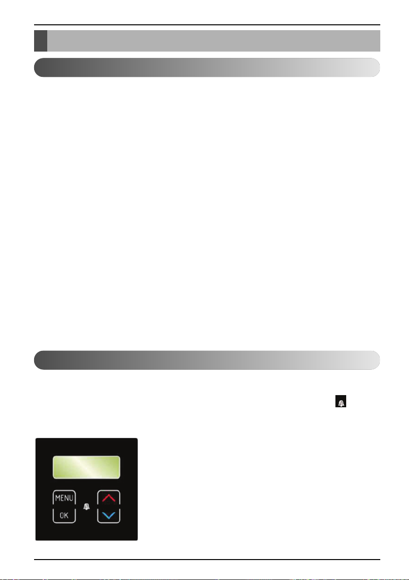
The device and heating system can be controlled with the use of 4 buttons on the controller interface
TERMOTRONIC. The controller interface has a 4-line LCD screen which displays the current state of
the device or controller and a LCD light indicator of malfunctions operation of the device ALARM).
The controller interface TERMOTRONIC in devices:
10 Air-to-Water Heat Pump
Page 11
TERMOTRONIC controller
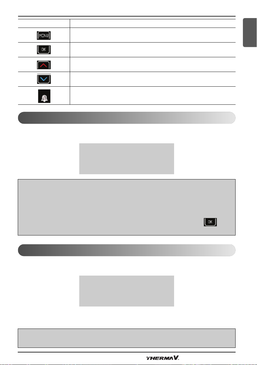
BUTTON BUTTON FUNCTION
MENU: Scrolls through the main menu and sub-menus.
ENTER: On, off, accessing the menu, accessing the settings and
confirming selected values.
»+«: Selects the values, by scrolling upwards the menus and sub-menus.
»-«: Selecting the values, scrolling down the menus and sub-menus.
ALARM: Indicates device malfunction.
Activating the device
After switching on the main switch or installation breaker, the interface screen displays the current
state of the device - for the short delay time. The device is not operational yet.
Standby................................
Heating 35.5°C
Return 35.3°C
DHW 49.0°C
NOTE
- The temperature values can differ from the above.
This also applies for all the following pictures.
- Before shutting down the device, if it is in a state of the device was in a state of HP STOP, it
returns to the HP STOP mode after switching on the main switch or installation breakers. The
display displays HP STOP. The device is switched ON by holding the (ENTER) key for 3
seconds - see below for more information.
ENGLISH
Operation of the device
After the start-up delay time, the device starts operating in the selected mode (heating, cooling or
heating DHW) according to present needs. The display displays the status:
Heating................................
Heating► 35.5°C
Return 35.5°C
DHW 49.0°C
In a scenario where the set temperature parameters (Heating, Return, DHW ...) is reached, the
device displays Standby.
NOTE
The delay of the start, of the device depends on the factory settings.
Owner’s Manual 11
Page 12
TERMOTRONIC controller
Standby
The device enters standby state when the values of the selected parameters Heating, Cooling, DHW,
device protection ... are reached. The display of the interface displays the status:
Standby................................
Heating 35.5°C
Return 35.3°C
DHW 49.0°C
NOTE
The device enters the standby mode even when any operation is protected (compressor start-up
delay, insufficient water flow).
Operation HP STOP
In case you want to shut down the device, press the (ENTER) key and hold it for 3 seconds.
The operation of the device is interrupted but the device is still active.
Standby................................
HP STOP 35.5°C
Return 35.3°C
DHW 49.0°C
The device can be turned on again by pressing the (ENTER) key and holding it for 3 seconds.
Device HP STOP
The device can be disconnected from the power supply by switching the main switch to position “0”
or disconnecting the installation breaker (the electrical power supply fuses).
NOTE
Devices must not be disconnected from the power supply for a lengthy period (via the main switch
or circuit breakers) as this will result in disabling the devices protection against water freezing in
the system which leads to complete device malfunction. Here the requirements from the
installation manual have to be considered.
12 Air-to-Water Heat Pump
Page 13
TERMOTRONIC controller
ENGLISH
Power outage
In case of a power outage, the device ceases to operate. After power is restored the device
undergoes 300 seconds of protection mode and then automatically returns to the mode before the
power outage. In case of a power outage, the controller retains all the settings that were set before
the outage.
NOTE
In case of a power outage longer than 2 hours air-water models with a water connection, water
has to be drained out from the connecting pipes between the external and the internal devices.
Operate in accordance with the specifications as described in the installation manual.
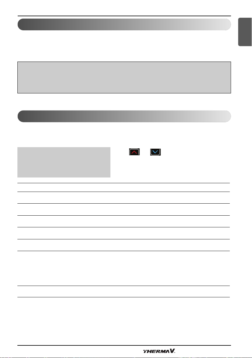
Display of the state of the device
After activating the power supply, the device displays current state of the device on the display
according to the operating mode and the values of basic parameters of the heating/cooling system of
the building.
Standby................................
Heating 35.5°C
Keys and allow scrolling up and
down the basic display.
Return 32.3°C
DHW 49.0°C
READING ON THE DISPLAY DESCRIPTION
Standby Current condition of operation.
Heating 35.5 °C Set or calculated temperature of heating (only in winter mode).
Return 32.3 °C Current temperature of the return.
DHW 49.0 °C Current temperature of DHW.
T outside 7 °C Current outside temperature.
Time left until the start of DHW thermal desinfection (i.e. next
thermal desinfection will begin in 12 days). Setting of DHW
TD60 after 12 days
2016/02/10 12:24 TUESDAY Current time and day of the week.
thermal desinfection is controlled by changing the parameters TD,
TD every and Start at described in section 6 of the basic menu
DHW.
Owner’s Manual 13
Page 14
TERMOTRONIC controller
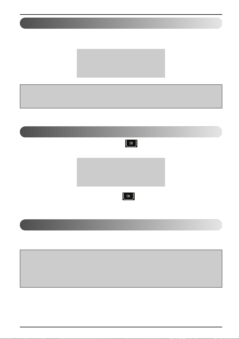
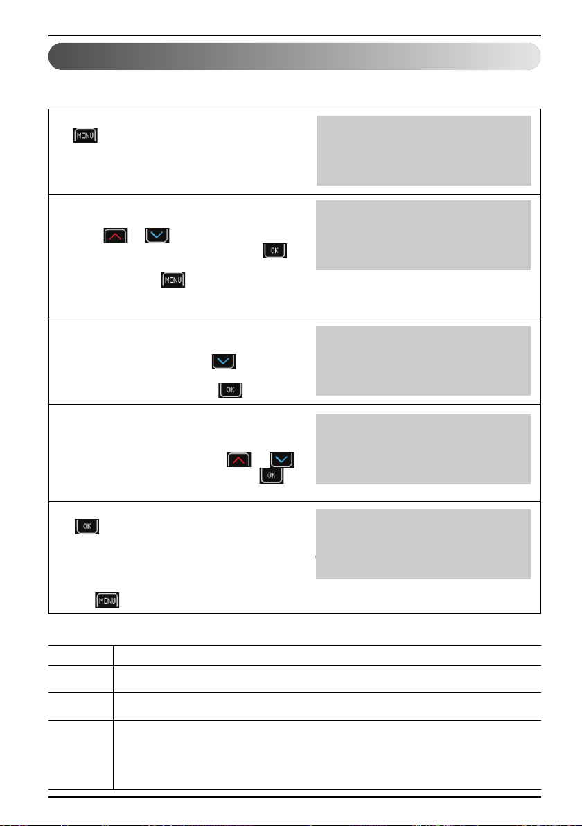
Setting parameters
All parameter settings of the device’s operation and heating/cooling system of the building are set as
described below.
For entering the user menu press the key
1
(MENU) on the basic display.
Standby................................
Heating 35.5°C
Return 32.3°C
DHW 49.0°C
The currently chosen menu is marked by the
2
symbols > < (CHOOSE).
Keys or select the desired menu.
To enter the selected menu, press the
(ENTER) key. For exiting the menus to the basic
display press the (MENU) key. The
display shows only those menus which were
actually activated during the start-up of the device.
After entering the selected menu, the initial
3
parameter is marked buy the symbols
> < (CHOOSE). The key selects the
parameter to change. When you select
the parameter, press the key (ENTER).
The signs * * along the chosen parameter
4
indicate the “mode setting” (SET). The value of
the chosen parameter can be changed to the
desired value by using the key or .
To confirm the settings, press the key
(ENTER).
After confirming the settings by pressing the key
5
(ENTER), the signs * * (SET) change
back into the signs > < (CHOOSE). For
changing the value of other parameters, repeat the
process. After completing the settings you can
return to the main menu by pressing the
key (MENU).
> Heating <
1. Circuit
2. Circuit
3. Circuit
C/W I
Schedule
>Normal 35.5°C <
Eco -2.0°C
C/W I
Schedule
*Normal 35.5°C *
Eco -2.0°C
C/W I
Schedule
>Normal 39.1°C <
Eco -2.0°C
<NOTE>
MARK DESCRIPTION
> < The arrows on the sides indicate the presently selected parameter/menu (CHOOSE).
* * The stars on the sides indicate the mode of setting the chosen parameter (SET).
A full arrow with the name of the parameter (i.e.: DHW ▶ 50 °C) indicates the current
▶
14 Air-to-Water Heat Pump
operation of the circulation pump or the position of the switching valve (i.e. DHW). In
the case of more circulation pumps of the heating system being in operation, more full
arrows are displayed.
Page 15
TERMOTRONIC controller
Setting the language
The controller enables setting different display languages. To set a language of your choice, follow
the steps below.
Press key (MENU) of the basic menu.
1
Standby................................
Heating 35.5°C
Return 32.3°C
DHW 49.0°C
ENGLISH
Use the key to choose the Mode
2
(Mode, Regime, Betriebsart, Nacin).
To confirm the settings, press the key
(ENTER).
Use the button to choose the parameter
3
Langugage EN (Jezik SI, Lingua IT,
Sprache DE, Jezik CRO).
To confirm the settings, press the key
(ENTER).
> Mode <
Temperatures
C/W ALL I
D8-PV Cooling
Silent mode
>Language EN <
Owner’s Manual 15
Page 16

Quick settings
Quick settings
NOTE
The parameters of the TERMOTRONIC controller were set according to project documentation of
the heating/cooling system, recommendations of the manufacturer for the device and your
requests by the authorized contractor. At handover, the contractor practically demonstrates
operation of the product and the important setting modes for each of the parameters.
The basic function of the device is switching ON the heating and DHW. The controller of the device
calculates the optimal required temperature of the hot water to achieve the desired air temperature of
the room by using information about the winter/summer operating mode, the chosen heating/cooling
and according to the external temperature.
Setting the temperature of heating/cooling
The temperature in the heated/cooled room is controlled in two stages, by setting the temperature:
1. of the room with the spatial corrector or thermostat and
2. the heating/cooling water in the accumulator and heating/cooling circuits on the controller
TERMOTRONIC.
NOTE
In a scenario where the heating/cooling circuit has been operated for a lengthy period of time (For
example, floor heating has been operated for 4 days at a stretch); but the desired temperature has
not yet been achieved, check the temperature settings of the water that is heated. This could
occur in spite of the change in setting of the temperature via a spatial corrector or thermostat.
16 Air-to-Water Heat Pump
Page 17

Quick settings
NOTE
- The space corrector influences the whole heating circuit and not the temperature of the individual
room. The desired room temperature where the spatial corrector is located in the reference
temperature for all other rooms of the heating circuit controlled by this spatial corrector. This is
why it must be located in a room where the desired temperature is as close to the desired
average temperature of the other rooms (halls, living room). It must not be located close to heat
sources (fireplace, TV, direct sunlight, etc.).
Before raising the temperature of heated water or the desired room temperature on the spatial
corrector make sure the valves on the heat sources in the room where it is too cold for you, are
completely or sufficiently opened. If the temperature of other rooms is too high or too low it is
necessary to sufficiently open or close the heat sources in the rooms where the deviations from
the desired temperature take place.
- For maintaining the correct operation of the heating system you have to choose a suitable
operating mode - winter (heating and DHW) or summer (DHW and cooling - only in certain
models).
ENGLISH
Owner’s Manual 17
Page 18

Quick settings
• Setting the room temperature with a room thermostat
For setting the room temperature with a room thermostat, read the manual that comes with the
product or consult the installer.
NOTE
- In case the thermostat is turned on all this time and the heating system does not heat/cool the
space to the desired temperature, check the settings of temperatures of the heating system on
the device.
- For choosing the function of heating or cooling an appropriate thermostat has to be installed
which allows both the functions.
- For maintaining the correct operation of the heating system, you have to choose a suitable
operating mode - winter (heating and DHW) or summer (DHW and cooling - only in certain
models).
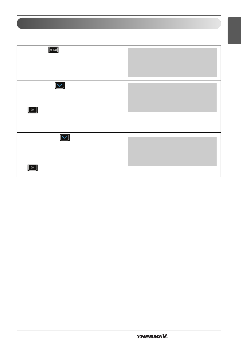
Setting the temperature of heated water
Upon start-up, the control of the hot water temperature was set to Heating mode which ensures the
most energy efficient operation for the device. In case, the automatically calculated temperature of
the heated water (in accordance with the external temperature) is inadequately heated, the
temperature of the heated water can quickly be raised or lowered by changing the parameter of
cooler/hotter (C/W).
The values of the parameter C/W are customisable. 1. Circuit 2. Circuit 3. Circuit or 4. Circuit
depending on which temperature you want to change.
NOTE
Upon start-up the heated water temperature control was set to Heating curve mode.
The authorised contractor has followed the specifications as mentioned in the the chapter 'Setings
of your Heating System at Startup' and has commissioned the system accordingly.
18 Air-to-Water Heat Pump
Page 19
Quick settings
By setting the parameter C/W you set the number of temperature steps for which you want to raise or
lower the temperature of heated water. You perform the settings in the following steps:
ENGLISH
Press key (MENU) in the basic menu.
1
In the user interface, use the key and
2
choose| menu 1. Circuit and press the key
(ENTER).
The first line has the parameter C/W selected.
3
To set the parameter press key (ENTER).
* * appear along the chosen parameter. The
4
keys and change the value of the
parameter C/W. This raises or lowers the
temperature of heated water.
Each pressing the key each time raises/
5
lowers the temperature of the heating circle for
one temperature step (<, >).
To confirm the settings press the key
(ENTER).
Standby................................
Heating 35.5°C
Return 32.3°C
DHW 49.0°C
Heating
> 1. Circuit <
2. Circuit
3. Circuit
>C/W I <
Schedule
Normal 35.5°C
Eco -2.0°C
*C/W I *
Schedule
Normal 35.5°C
Eco -2.0°C
*C/W I>> *
Schedule
Normal 35.5°C
Eco -2.0°C
After conformation the controller calculates the
6
new temperature setting for the heating circuit
or heated water according to the external
temperature (in case of weather control).
For returning to the basic view press the key
(MENU) twice.
*C/W I>> *
Schedule
Normal 35.5°C
Eco -2.0°C
Owner’s Manual 19
Page 20

Quick settings
For advanced changing the temperature of the heated water control mode of the heating system
refer to the Chapter(Heating setting).
NOTE
- The temperature of heated water can be raised or lowered for no more than four temperature
steps.
- The heating and individual circuits settings are separated from the cooling, this is why all settings
for heating remain unchanged with the change of the mode into cooling. The same is true for
parameter settings in the menu Cooling, 1. Circuit, 2. Circuit, 3. Circuit, 4. Circuit and Heating,
which are separated so as to maintain all settings when changing the heating Mode
(winter/summer).
- For heating curve you can choose various temperature modes of operation with setting daily and
weekly schedules.
- In case of radiator heating for a significant change, change the parameter C/W for 2 or 3
temperature steps at once but only for 1 temperature step in case of floor heating.
Please note that the responsiveness of the heating system in the case of radiator heating is
quicker than in the case of floor heating. By changing the parameter C/W several hours can pass
(in the case of floor heating) before the heating system responds properly and you can feel the
change of the adjustment.
20 Air-to-Water Heat Pump
Page 21

Quick settings
Setting the temperature of DHW
The device heats the water in a DHW via heat exchanger. ln case the DHW requires to be heated,
the controller switches the device from heating the building to heating the DHW. Heating DHW has
priority over other modes of operation.
Setting the temperature of DHW is performed in the following steps:
ENGLISH
Press key (MENU) on the Home screen.
1
In the user menu, choose the menu DHW using
2
the key and press the key (ENTER).
In the DHW menu, in the first line the parameter
3
DHW is chosen. To set the parameter press key
(ENTER).
The chosen parameter is displayed within * *.
Scroll the keys and change the value
4
of the parameter DHW. This raises or lowers the
temperature of DHW.
To confirm the settings press key
(ENTER).
The set parameter is displayed within > <.
5
For returning to the home screen, press the key
(ENTER) twice.
Standby................................
Heating 35.5°C
Return 32.3°C
DHW 49.0°C
> DHW <
Additional source
Mode
Temperatures
>DHW 50.0°C<
Hysteresis 5.0°C
Schedule
Circulation Sched.
*DHW 50.0°C*
Hysteresis 5.0°C
Schedule
Circulation Sched.
>DHW 50.0°C<
Hysteresis 5.0°C
Schedule
Circulation Sched.
NOTE
- For controlling the temperature settings of in the DHW, you can set different modes of operation
(ECO, Comfort), daily and weekly schedules.
Owner’s Manual 21
Page 22
Quick settings
Changing the operational mode - winter/summer mode
The mode of operation - winter or summer, is chosen according to season. When you prefer to have
cool air indoors, switch to the summer operating mode. When you prefer warm air indoors, switch to
the winter mode. The choice can be automatic or manual.
NOTE
- If you do not operate the summer mode during summer season, this can result in higher energy
consumption. The operational costs will be increased for two reasons:
▶ The main circulation pump will switch on from time to time to check whether the need for
heating has arisen.
▶ The additional source could also be turned on (for the protection of the heating system) if the
temperature falls below a certain point (18 °C depending on the start-up settings).
- The cooling function is only provided by reversible devices and the passive models of the
devices.
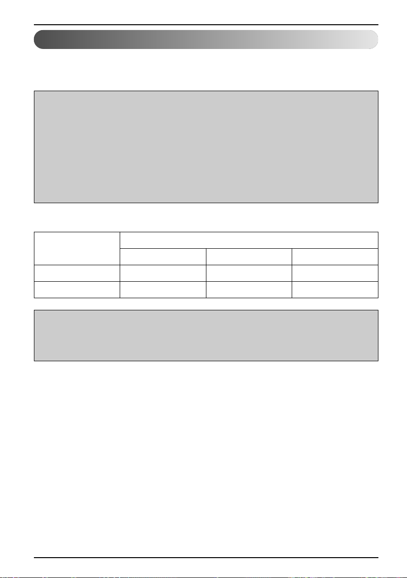
The function of the device according to the chosen mode of operation:
Mode
Heating DHW Cooling
Winter YES YES NO
Summer NO YES YES
OPERATION
NOTE
In the winter mode (heating and DHW) the heating system works only for heating the water in the
dedicated circuits and DHW. By using the built-in external switch, we can manually switch on/off
the cooling mode of the device.
22 Air-to-Water Heat Pump
Page 23

Quick settings
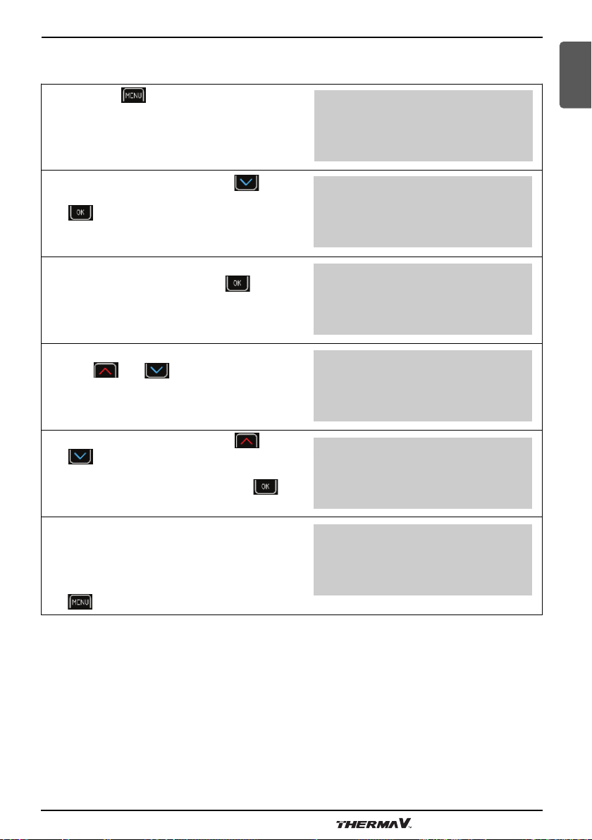
• Changing the operating mode
Changing the operation from winter to summer mode is performed in the following steps:
ENGLISH
Press key (MENU) in the basic menu.
1
In the user interface, use the key and
2
choose the menu Mode.
To choose the menu Mode press the key
3
(ENTER).
In the first line, the parameter Mode is selected
4
as Winter. To set the parameter press the key
(ENTER).
The chosen parameter is displayed within * *.
5
Scroll the keys or to change the value
of the parameter into:
Mode summer for cooling and heating of
DHW or Mode winter for heating and cooling
of DHW or Mode AUTO for automatic switch
between winter and summer mode of operation.
To confirm the settings, press the key (ENTER).
Standby................................
Heating 35.5°C
Return 32.3°C
DHW 49.0°C
> Heating <
1. Circuit
2. Circuit
3. Circuit
> Mode <
Temperatures
>Mode Winter<
Screed drying NO
Initial
Maximum
*Mode Winter*
Screed drying NE
Initial
Maximum
For returning to the home screen, press the key
6
NOTE
Setting the AUTO mode allows an automatic switch of the operating mode after the external
temperature at 9 PM is higher or lower than the temperature of the switch (12 °C) for 3 days. This
setting can be changed with the parameter Temp. mode in the menu Mode
(MENU) twice.
>Mode Summer<
Screed drying NO
Initial
Maximum
Owner’s Manual 23
Page 24

Quick settings
Setting the cooling temperature
In the operating mode (Summer, AUTO) which enables cooling, you can adjust the temperature of
cold water for the cooling circuits. The controller only enables the mode of controlling the temperature
of cold water while maintaining constant temperature.
NOTE
For setting the cooling of the building the Summer or AUTO Mode must be chosen.
Setting the temperature of cold water is performed in the following steps:
Press key (MENU) in the basic menu.
1
Choose the menu Cooling or use the key
2
to choose the desired Circuit in the first menu.
To set the parameter press the key
(ENTER).
In the menu Cooling (or Circuit) use the key
3
4
5
to choose the parameter Normal and
press the key (ENTER).
The chosen parameter is displayed within * *.
Use the key or to change the value of
the parameter Normal; either to raise or lower
the temperature of the accumulator (or circuit).
To confirm the settings press key
(ENTER).
For returning to the home screen, press the key
(MENU) twice.
Standby................................
Cooling 13.5°C
Return 14.3°C
DHW 49.0°C
> Cooling <
1. Circuit
2. Circuit
3. Circuit
Schedule
>Normal 13.5°C<
Eco -2.0°C
Comfort 0.0°C
Schedule
*Normal 12.5°C*
Eco -2.0°C
Comfort 0.0°C
Schedule
>Normal 12.5°C<
Eco -2.0°C
Comfort 0.0°C
24 Air-to-Water Heat Pump
Page 25

Quick settings
NOTE
- The cooling and individual circuits settings are separated from the heating, hence the settings
that have been configured for the cooling mode remain unchanged while operating in the heating
mode.
- In the case of floor, ceiling or wall cooling appropriate settings and protection to prevent causing
surface condensation.
- For controlling the temperature settings of cooling water, you can set different temperature
modes, daily and weekly schedules.
- The response of the cooling system in a condenser is quicker than in floor, ceiling or wall cooling.
ENGLISH
Switching on the additional heat source
In case the heating capacity of the device is not sufficient for covering thermal losses of the building
under given weather conditions, you can increase the capacity by switching on the Additional
source.
The device has a Backup source, a flow electric water heater fitted as standard which can function as
an additional heat source by activating the parameter Additional source. Basically, the controller is set
to activate the additional source which operates parallel to the device if the external air temperature
falls below -5 °C. This setting is set according to the building at commissioning and can be changed
later. Before setting the parameter, we advise consulting the contractor for commissioning.
NOTE
In case you would like to use an oil/gas/pellet furnace or external electric heater as auxiliary heat
source, you have to ask the contractor for commissions to perform the setting.
Activating the additional source manually is performed in the following steps:
Press key (MENU) in the basic menu.
1
In the user menu choose the menu Additional
2
source using the key and press the key
(ENTER).
In the first line choose the parameter bold
3
and press the key (ENTER).
Standby................................
Heating 35.5°C
Return 32.3°C
DHW 49.0°C
> Additional source <
Mode
Temperatures
>Switch o Need<
Bi-point -5.0°C
Delay 30 min
Mode PARALLEL
Owner’s Manual 25
Page 26

Quick settings
The chosen parameter is displayed within * *.
4
The keys and change the value of
the parameter bold constant. The auxiliary
source will operate together with the heat pump.
To confirm the settings press key ENTER.
For returning to the basic view press the key
5
6
NOTE
When additional heat power is not required, it is recommended to switch from the auxiliary heat
source back to the normal operation.
(MENU) twice.
In the first row, after switching on the Backup
source, the main display will display the
information about the status of the device
Heating+AdHeater.
>Switch o constant<
Bi-point -5.0°C
Delay 30 min
Mode PARALLEL
>Activate constant <
Bi-point -5.0°C
Delay 30 min
Mode PARALLEL
Heating + add. source
Heating ► 40°C
Return 32.3°C
DHW 49.0°C
Manual activation of the additional heat source
In case the device does not operate as required, we recommend activating the additional source- the
flow electrical water heater which will take over the heating of the dedicated circuits and DHW.
Activating the backup source manually is performed in the following steps:
Press key (MENU) in the basic menu.
1
In the user menu choose the menu Additional
2
source using the key and press the key
(ENTER).
26 Air-to-Water Heat Pump
Standby................................
Heating 35.5°C
Return 32.3°C
DHW 49.0°C
> Additional source <
Mode
Temperatures
Page 27

In the menu Additional source choose
3
AddSourceOnly as NO using the key and
press the key (ENTER).
Quick settings
ENGLISH
Delay OFF
Mode PARALLEL
Rise for 5.0°C
>AddSourceOnly NO<
The chosen parameter is displayed within * *.
4
Use the key to change the value of the
parameter to add. source only as YES.
This ensures that the source runs.
To confirm the settings, press key (ENTER).
For returning to the home screen, press the key
5
6
NOTE
The device in this mode can heat the circuit and DHW.
- The heating water will heat to the temperature set in the basic menu Heating, 1. Circuit, 2.
- The DHW will heat up to the temperature set as DHW in the menu Backup source.
As soon as heating with the device is resumed, set the parameter to AddSourceOnly NO.
(MENU) twice.
In the first row, after switching on the Backup
source, the main display displays the
information about the status of the device
Heating - AddSourceOnly -.
Circuit, 3. Circuit, and 4. Circuit. In the case of a FP error the temperature of heating water will
heat up to the set temperature with the parameter AntiFreeze in the menu AddSourceOnly.
Delay OFF
Mode PARALLEL
Rise for 5.0°C
* AddSourceOnly YES*
Delay OFF
Mode PARALLEL
Rise for 5.0°C
>AddSourceOnly YES<
Heating - AddSourceOnly Heating ► 40 °C
Return 32.3°C
DHW 49.0°C
Owner’s Manual 27
Page 28

Advanced settings
Advanced settings
In this chapter you will find:
- How to set the parameters of the device in case the system has no controller or thermostat built in
or the settings for the temperature of heated water does suffice the heating needs.
- How to set the control mode of the heating water.
- How to set the mode of operation for heating water/cooling water, heating/cooling circuits and
heating of DHW.
- How to set working schedules ...
For easier understanding of the chapter, you can find a general scheme of the heating (cooling)
system below.
A
C
B
M5
M6 M9
M7
M10
M11
M12
F
M4
D
E
ELEMENTS MARK CHARACTERISTICS
A Utility room
B Heating circuits
C Hydro module
D Domestic hot water
E Heat consumers (floor heating / radiators)
F Heat pump
M4 Circulating pump for DHW
M5 Circulation pump of direct heating circle 1
M6 Circulation pump of mixing-heating circle 2
M7 Mixing valve of mixing-heating circle 2
M9 Circulation pump of mixing-heating circle 3
M10 Mixing valve of mixing-heating circle 3
M11 Circulation pump of mixing-heating circle 4
M12 Mixing valve of mixing-heating circle 4
28 Air-to-Water Heat Pump
Page 29

Advanced settings
NOTE
- Heating circle 1 (M5) can only be a direct heating circle (without mixing valve).
For this circuit we always choose the heating circle which requires the highest temperature (i.e.
radiators).
- Heating circuits 2, 3 and 4 (M6, M9, M11) can be direct (without a mixing valve) or mixing
circuits. In case of direct circuits, temperature settings of the heated water can be adjusted in the
menu Heating.
Heating settings
NOTE
While setting, or changing the desired temperature of the heated water ensure that in case when
the contractor for commissioning, set the parameter (371) Buff.tank to constant (noted in chapter
11) the values set as Normal and Correction in the menus Heating have to be higher than the
setting of desired values in the mixing circuits (1. Circuit, 2. Circuit, 3. Circuit, and 4. Circuit) if they
are active.
• Heating water control mode
The controller of the device enables two ways of controlling the temperature of heated water at the
exit of the device or the entry into individual heating circuits:
a) Heating Curve: Setting the desired temperature of heated water according to the external
temperature.
b) Constant: The temperature of heating water is kept constant regardless of the external
temperature.
ENGLISH
The control mode of the heating water suitable for individual buildings depends on various factors
such as the type of building, its size, make of the heater ...; this is why the control mode for heating
water temperature is set by a Commissioning Engineer. Nevertheless, you can change the setting
later.
For a comfortable environment, it is recommended to set the default control mode as Heating Curve the setting set at commission. Heating curve means a more effective operation of the heating system
because by raising external temperature the desired temperature of heated water is lowered.
Owner’s Manual 29
Page 30

Advanced settings
Control modes for heating water have to be set separately by type in menus:
► Heating…………………
► 1. Circuit,
► 2. Circuit,
► 3. Circuit,
► 4. Circuit,
It is important to note that the method of adjustment is the same in all cases and is described as a
heating curve example for the section 'Weather controlled heating' and as control at constant
temperature example for the section 'Heating based..' in Section(Heating based on constant
temperature).
• The change in heating control heating curve - constant temperature
You can switch the heating control from heating curve to a constant temperature, follow the below
steps:
Press key (MENU) on the home screen.
1
Choose the menu Heating or use the key
2
to choose the desired Circuit. To set the
parameter press key (ENTER).
Choose the Heating curve parameter by
3
pressing and press the (ENTER)
key.
The chosen parameter is displayed within * *.
4
By pressing the key adjust the value of the
Heating curve parameter as Const.
temperature and confirm the settings by
pressing the key (ENTER).
For returning to the home screen press the key
5
(MENU) twice.
Standby................................
Heating 35.5°C
Return 32.3°C
DHW 49.0°C
> Heating <
1. Circuit
2. Circuit
3. Circuit
Normal 35.5°C
Eco -2.0°C
Standby 3.0°C
>Heating curve ..................<
Normal 35.5°C
Eco -2.0°C
Standby 3.0°C
*Const. temperature..........*
Normal 35.5°C
Eco -2.0°C
Standby 3.0°C
*Const. temperature..........*
30 Air-to-Water Heat Pump
Page 31

Advanced settings
• Weather controlled heating
ENGLISH
Weather controlled heating means water temperature in the heater is adjusted to the current air
temperature. The lower the external temperature, the higher the heat loss and as a result a higher
temperature of water is required for the heating bodies (floor, wall or radiator heating...) to
compensate for the loss in heat.
The opposite is true in case of higher external temperatures. In this case the heat losses are lower
and a low temperature is required to compensate for the losses.
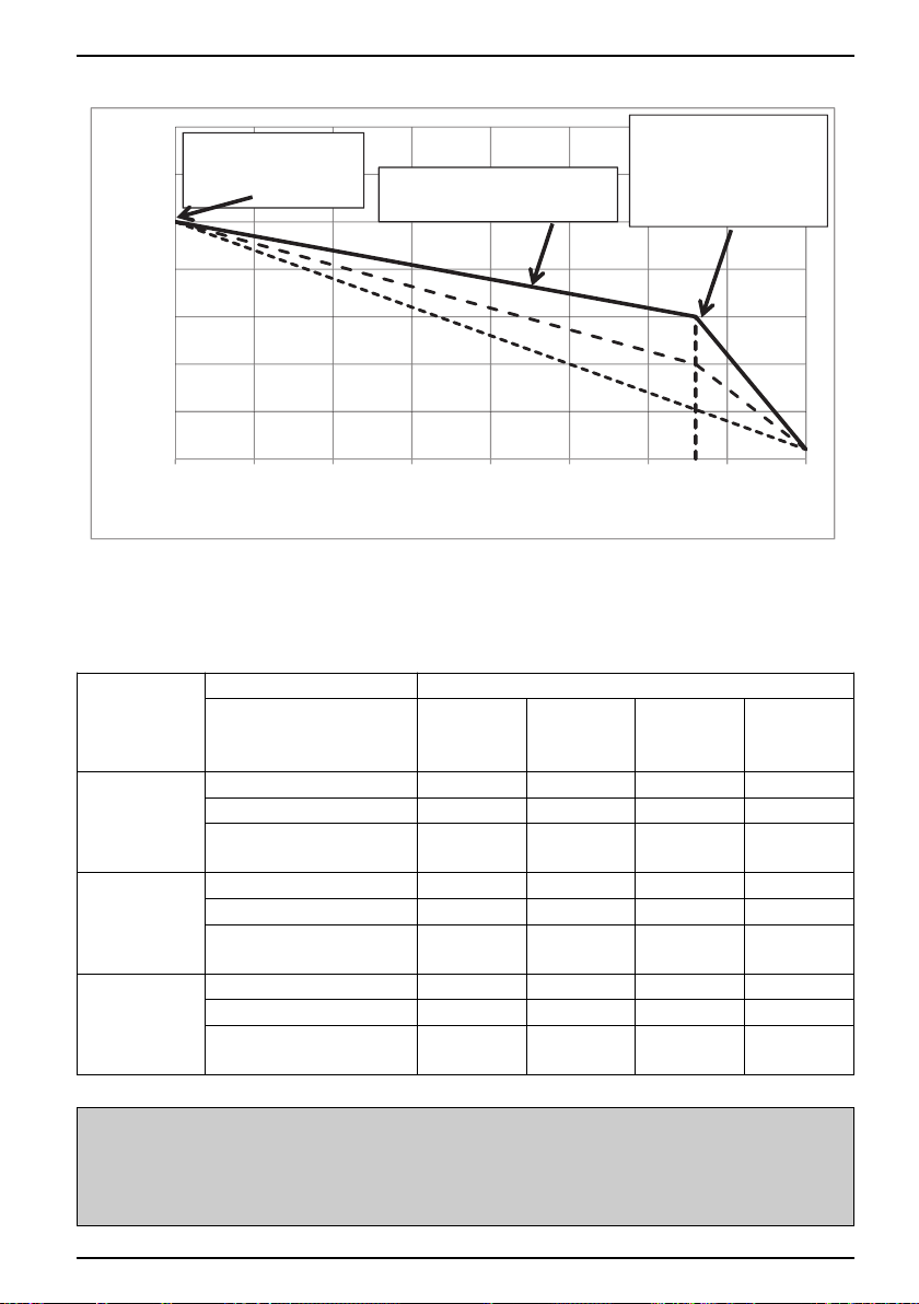
The weather controlled heating curve shows that the value for 'Return' depends on the temperature
of air outside the building. The lower the external air temperature, the higher the calculated needed
value for 'Return'.
In weather controlled heating you can set two parameters:
- Normal: With this parameter, you set the desired value for the parameter 'Return' while the external
temperature is -18 ℃
- Correction: With this parameter you can set the heating curve temperature while the external
temperature is 15 ℃. It is mainly important for transitional periods because the weather controlled
heating curve temperature can be too low at this time, depending on the building and desired
comfort.
The parameters Normal, Standby and Correction can be changed to the desired values using the
keys or .
Owner’s Manual 31
Page 32
Advanced settings
20
25
30
35
40
45
50
55
-18 -13 -8 -3 2 7 12 17 22
Temperature of heating water [°C]
Temperature of external air [°C]
Setting of weather
controlled heating
Normal
Setting of breaking
point for the weather
guided heating -
transitional period
Correction
15
The weather controlled heating curve
At current temperature of
external air.
The appropriate heating temperature setting is essential for ensuring the desired comfort. It depends
on the characteristics of the house and heating objects as well as the project temperature.
The table below lists the recommended settings which can help you decide on the appropriate
parameters of the weather controlled heating.
PARAMETER HEATING (weather controlled)
TYPE OF
HOUSE
Heating, 1. Circuit,
2. Circuit, 3. Circuit, and
4. Circuit
Floor, wall
[°C]
Convector
heating [°C]
Radiation
heating 55 °C
Radiation
heating 65 °C
Normal - 55 65 70
Noninsulated
house
Insulated
house
Wellinsulated
house
NOTE
Standby 3 5 5 7
Correction - Correction of
breaking point (+15 °C)
Normal 35 50 55 65
Standby 2 5 5 6
Correction - Correction of
breaking point (+15 °C)
Normal 30 40 55 55
- 10 13 15
5 5 10 12
Standby 2 5 5 5
Correction - Correction of
breaking point (+15 °C)
3 3 5 10
In mixing heating circuits, you set the temperature of the supply water (outlet water temperature –
parameter Flow), in direct heating circuits and on the device, we adjust the temperature of the
return (inlet water temperature – parameter Return).
32 Air-to-Water Heat Pump
Page 33

Advanced settings
• Setting the temperature correction of heating water
By changing the value of the parameter Correction you can adjust the temperature of heated water
in transitional periods and thus adjust the desired comfort in the heated building. Follow the below
steps:
ENGLISH
Press key (MENU) in the basic menu.
1
The first line has the parameter Heating
selected. To set the parameter press key
2
(ENTER).
Choose the Correction parameter by pressing
3
4
• Setting the heating curve temperature - Normal
By using the parameter Normal, you can set the maximal heating temperature while the external
temperature is -18 ℃.
and press the (ENTER) key.
The chosen parameter is displayed within * *.
The keys and change the value of the
parameter Correction. The temperature can be
raised for no more than 15 K (°C).
For returning to the basic view press the key
(MENU) twice.
Standby................................
Heating 35.5°C
Return 32.3°C
DHW 49.0°C
> Heating <
1. Circuit
2. Circuit
3. Circuit
Comfort 2.0°C
Hysteresis 3.0°C
Heating Curve
>Correction 5.0°C<
Comfort 2.0°C
Hysteresis 3.0°C
Heating Curve
*Correction 5.0°C*
NOTE
After start-up of the device, it is not advisable to alter the value for the parameter 'Normal' unless
the heating system is subjected to mechanical changes.
Owner’s Manual 33
Page 34

Advanced settings
You perform the settings in the following steps:
Press key (MENU) in the basic menu.
1
The first line has the parameter Heating
2
selected. To set the parameter press key
(ENTER).
Choose the parameter Normal by pressing
3
4
5
and press the (ENTER) key.
The chosen parameter is displayed within * *.
The keys and change the value of the
parameter Normal. This way you raise or lower
the maximal temperature of heating water while
the external temperature is -18 ℃. To confirm
the settings press key (ENTER).
The recommended values of the maximal
temperature for individual types of heating are
mentioned in chapter(Heating setting)
After confirming the settings the controller
calculates the new temperature setting of the
heating water according to external temperature
(weather control); if the external temperature is
higher than -18 °C, this temperature is different
from the set temperature. For returning to the
basic view press the key (MENU) twice
Standby................................
Heating 35.5°C
Return 32.3°C
DHW 49.0°C
> Heating <
1. Circuit
2. Circuit
3. Circuit
C/W I
Schedule
>Normal 35.5°C <
Eco -2.0°C
C/W I
Schedule
*Normal 45.0°C*
Eco -2.0°C
C/W I
Schedule
>Normal 45°C <
Eco -2.0°C
NOTE
- In case when contractor for commissioning in chapter 11, set the parameter (371) Buff.tank to
constant, the values of the parameter Normal in the menus 1. Circuit, 2.Circuit, 3. Circuit or 4.
Circuit must always be set to an equal or lower value than the value of the parameter Normal in
the menu Heating.
- For economical use of heating we recommend the use of heating curve mode.
- For heating curve you can choose various temperature modes of operation with setting daily and
weekly schedules.
34 Air-to-Water Heat Pump
Page 35
Advanced settings
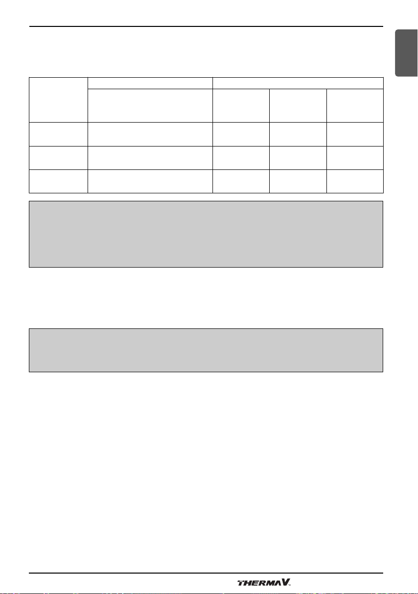
• Heating based on constant temperature
For ensuring economic feasibility of the whole system, it is advisable to set the default setting to
'Heating Curve'. If you prefer to set a constant temperature for the indoors, follow the below
settings:
PARAMETER HEATING (with constant temperature)
TYPE OF
HOUSE
Heating, 1. Circuit, 2. Circuit,
3. Circuit, and 4. Circuit
Floor, wall [°C]
Convector
heating [°C]
Radiation
heating 55 °C
ENGLISH
Noninsulated
house
Insulated
house
Wellinsulated
house
Normal 38 50 50
Normal 35 45 47
Normal 30 40 45
NOTE
In mixing heating circuits, you set the temperature of the supply water (water leaving the device in
to the heating bodies (floor, wall or radiator heating), in direct heating circuit and on the device, we
adjust the temperature of the return (water entering the device from the heating bodies (floor, wall
or radiator heating)).
• Setting the temperature of heated water
You can set a value for the parameter Normal irrespective of the external temperature.
NOTE
After start-up of the device, it is not advisable to alter the value for the parameter 'Normal' unless
the heating system is subjected to mechanical changes.
Owner’s Manual 35
Page 36

Advanced settings
You perform the settings in the following steps:
Press key (MENU) in the basic menu.
1
The first line has the parameter Heating
2
selected. To set the parameter press key
(ENTER).
Choose the parameter Normal by pressing
3
4
5
and press the (ENTER) key.
The chosen parameter is displayed within * *.
The keys and change the value of the
parameter Normal. To confirm the
settings press key (ENTER).
The recommended values of the maximal
temperature for individual types of heating are
given in chapter(Heating setting)
After confirming the settings, the device will
heat the water to the set temperature regardless
of the outside air temperature.
For returning to the basic view press the key
(MENU) twice.
Standby................................
Heating 35.5°C
Return 32.3°C
DHW 49.0°C
Heating
> 1. Circuit <
2. Circuit
3. Circuit
C/W I
Schedule
>Normal 35.5°C <
Eco -2.0°C
C/W I
Schedule
*Normal 45.0°C*
Eco -2.0°C
C/W I
Schedule
>Normal 45°C<
Eco -2.0°C
NOTE
- In case when contractor for commissioning in chapter 11, set the parameter (371) Buff.tank to
constant, the values of the parameter Normal in the menus 1. Circuit, 2. Circuit, 3. Circuit or 4.
Circuit must always be set to an equal or lower value than the value of the parameter Normal in
the menu Heating.
- For economical use of heating we recommend the use of heating curve mode.
- For heating curve you can choose various temperature modes of operation with setting daily and
weekly schedules.
36 Air-to-Water Heat Pump
Page 37

Advanced settings
ENGLISH
Operating mode
The controller of the device enables heating of the heating water/ cooling of the cooling water,
heating/cooling of the circuits and DHW in four different operational modes:
► Normal applies to heating/cooling.
► DHW applies to the heating of DHW.
► ECO.
► COMFORT.
These different ways of operation can later be used for setting timetables.
The parameter ECO is used for the economic feasibility which implies lowering/raising the desired
temperature as set for the heating/cooling mode respectively.
The parameter COMFORT is used for the operation which means greater comfort by raising/lowering
the temperature of water that has been set for the heating/cooling mode respectively.
In case you want to change the entire system to ECO or COMFORT, you can intend to change the
mode of operation from AUTO to Operation ECO or Operation COMFORT.
Setting the cooling system
You turn on the cooling mode by entering the menu mode and changing the parameter mode Winter
to mode Summer.
- To turn on the cooling according to schedule you have to set the operating schedule for cooling in
the menu Cooling. The display and settings of the Cooling menu are enabled only if the conditions
of the mode’s operation listed in the Section(Changing the operational mode-winter/summer mode)
are met (chosen mode + reversible heat pump).
• Active cooling
Cooling can be set for every parameter described in the table below separately.
In case of active cooling we recommend the following cooling settings:
PARAMETER COOLING
Cooling, 1. Circuit, 2. Circuit, 3. Circuit, and 4. Circuit
Normal 19-20 12-15
Floor, wall, ceiling
[°C]
Convector heating
Owner’s Manual 37
[°C]
Page 38

Advanced settings
NOTE
- In mixing heating circuits the temperature of the supply pipe can be set in direct heating circuits
and set the Return temperature.
-
Active cooling works in the area set in the menu Cooling with the parameters T.out.max.- external
temperature above which the active cooling can operate actively and the parameter Min - external
temperature until which the active cooling can operate.
Schedules
• Operating mode
Every function (heating, cooling, 1. Circuit, 2. Circuit, 3. Circuit, 4. Circuit, DHW, pool, silent
operation and circulation) can operate in several ways. Setting the operation mode for individual
functions are performed in the schedule for this function.
In heating, cooling, mixing circuits, heating of DHW and swimming pool heating there can be 4
different types of operation:
- OFF: Heating/cooling is disabled.
- HEA of COL: Operation in the heating or cooling mode (parameter Normal).
- ECO: In this mode the controller maintains the temperature which is lower by the value of the
ECO parameter than the set temperature in the parameter Normal. In case of cooling the
temperature set in this mode is higher by the value of the ECO parameter than the set
temperature in the parameter Normal. In this mode operation is more economical.
- COM: In this mode the controller maintains the temperature which is higher by the value of the
COM parameter than the set temperature in the parameter Normal. In case of cooling the
temperature set in this mode is lower by the value of the COM parameter than the set temperature
in the parameter Normal. In this mode operation is less economical, depending on the setting it
can also be more comfortable.
In circulation of DHW two operation settings are possible:
- OFF: Circulation pump is disabled.
- CIR: Circulation pump is truned on.
These units enable two additional operation modes set in the menu Mode with the parameter Silent
mode
- NRM: Normal operation in the heating or cooling mode.
- LOW: Lowered operation mode in the heating or cooling mode.
38 Air-to-Water Heat Pump
Page 39

Advanced settings
The schedule enables daily settings of 6 operation mode switches. Below is a description of heating
ENGLISH
with an example of a daily schedule.
COMFORT
Normal
ECO
OFF
024681012141618202224
Time of day [h]
Heating is turned off (OFF) from 00:00 to 02:00.
The heating is turned on at 02:00 in the COMFORT mode (in this mode the temperature is higher
than the temperature set in the parameter Normal by the COM parameter).
The heating is turned on at 07:00 in the ECO mode (in this mode the temperature is lower than the
temperature set in the parameter Normal by the ECO parameter).
At 1:00 PM the operating mode switches to COMFORT.
AT 5:00 MP the operating mode switches to Normal (the temperature set or calculated in the
parameter Normal). At 9:00 PM the heating turns off (OFF).
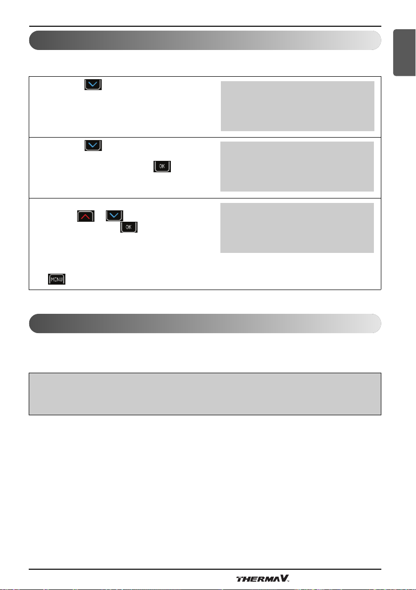
You perform the settings in the following steps:
In the menus Heating, Cooling, Circuits, choose the
parameter Schedule using the key.
When the symbols > < appear next to the
parameter Schedule, press the key (ENTER).
Choose the day you would like to set the schedule
by using keys or .
When you choose the day press the key
(ENTER).
The time when the switch-over blinks. By pressing
the key (ENTER) confirm that you wish to set
the time.
Symbols XXXXX start blinking as an indication to
enter the time. Set the desired time using the key of
the switch-over (in 15 min). To confirm the set
time press key (ENTER). The symbols
XXXXX cease to blink after the time has been set.
C/W I
>Schedule <
Normal 35.5°C
Eco -2.0°C
MON Copy DELETE
00:00 HEA --:-- HEA
--:-- HEA --:-- HEA
--:-- HEA --:-- HEA
MON Copy DELETE
00:00 HEA --:-- HEA
--:-- HEA --:-- HEA
--:-- HEA --:-- HEA
Owner’s Manual 39
Page 40

Advanced settings
By pressing you can access the field for
choosing the mode of operation. This field starts
blinking. By pressing the key (ENTER)
confirm you want to set the mode of operation.
Symbols XXX start blinking over the operating
mode. Use keys or to choose the
suitable mode of operation along the set time. To
confirm the operating mode press key
(ENTER). Symbols XXX cease to blink after the
operating mode has been set.
MON Copy DELETE
00:00 OFF --:-- OFF
--:-- OFF --:-- OFF
--:-- OFF --:-- OFF
NOTE
Once you have set the operating mode it continues to be used until a new one is set.
I.e. if you set the heating to OFF on Monday and you do not set anything for the following days,
the heating will be OFF for all the following days as well because there was no change of
operation mode.
Use the key to navigate to the time set for the
next switch-over of the operating mode. Perform the
settings the same as for the first switch-over.
MON Copy DELETE
00:00 HEA --:-- HEA
--:-- HEA --:-- HEA
--:-- HEA --:-- HEA
To switch the heating to the COMFORT mode,
choose COM. To switch the heating to the ECO
mode, choose ECO. To switch to the Normal mode,
choose HEA or COL. To switch off the heating,
choose OFF.
MON Copy DELETE
00:00 HEA --:-- COM
02:00 COM --:-- COM
--:-- COM --:-- COM
When you set the schedule you can use the key (MENU) to return to the menu.
The set schedule can be copied to the following day by using the following steps:
Use the key to navigate to Copy which starts
blinking. Press the key (ENTER).
MON Copy DELETE
00:00 OFF 13:00 COM
02:00 COM 17:00 HEA
07:00 ECO 21:00 OFF
The controller displays the question whether you
would like to copy the currently chosen schedule to
the following day. To confirm, press key
(ENTER). If you do not want to confirm, press key
(MENU).
Use this method to copy the schedule for all days of
the week.
***************************
* ? COPY ? *
* TUESDAY *
***************************
TUE Copy DELETE
00:00 OFF 13:00 COM
02:00 COM 17:00 HEA
07:00 ECO 21:00 OFF
40 Air-to-Water Heat Pump
Page 41

To delete the schedule for a chosen day, follow the below steps:
Advanced settings
ENGLISH
Use the key to navigate to delete, which
starts blinking. Press the key (ENTER).
TUE Copy DELETE
00:00 HEA --:-- HEA
--:-- HEA --:-- HEA
--:-- HEA --:-- HEA
The controller displays the question whether you
would like to delete the currently chosen schedule.
To confirm, press key (ENTER).
If you do not want to confirm, press key
(MENU).
You have now deleted all the settings for the chosen day.
The chosen day displays settings of the
previous day.
***************************
* ? DELETE ? *
***************************
TUE Copy DELETE
00:00 OFF 13:00 COM
02:00 COM 17:00 HEA
07:00 ECO 21:00 OFF
After performing the setting you can use the key (MENU) to return to the menu.
Owner’s Manual 41
Page 42

Advanced settings
Alternative source
NOTE
For this function and to display the menu Alternative source on the TERMOTRONIC controller you
need the extension regulation with the input-output module TT3003.
The alternative source function uses the heat from the solar collectors (SSE) or for using
heat from the biomass DHWs. Settings related to this function can be set in the Alternative Source
menu. Heating the DHW initiates when temperature of the alternative source reaches the value for
parameter Dif.Min. Heating the DHW continues until the SetTemp. value is reached.
When heating initiates, the setting of the parameter Prior.DHW is enabled. When the Set.Temp has
been reached, the buffer tank starts heating. After the water attains the maximum temperature in the
buffer tank, the heating of the DHW resumes until it reaches the Set.Temp. However, if the
temperature of the alternative source is higher than that of the buffer tank, the heating continues until
it reaches the Max.Temp.
When the buffer tank and DHW reach the maximal temperature, heating with the alternative source
stops.
In case the temperature of the alternative source reaches the temperature of protection (parameter
protection), a signal turns on which can control the users to lower the temperature of the alternative
source.
NOTE
We recommend keeping the settings set by the authorized contractor.
Press key (MENU) in the basic menu.
1
In the user menu choose the menu Alternative
source with the key and press the key
(ENTER).
> Alternative source <
42 Air-to-Water Heat Pump
Backup source
Mode
Temperatures
Page 43

Advanced settings
ENGLISH
Programme for drying screeds
The controller has a built in function of gradual drying of screeds which is especially important for
new buildings and before installing flooring.
Before using the programme for drying screeds you have to consult the contractor for screeds.
According to his requirements you can use the standard programme or adjust it.
The programme for drying screeds is located in the menu mode.
• Standard programme
This programme consists of 8 steps and is normally adjusted for all systems of floor heating. Before
activating this programme you have to set the maximal allowed temperature of the return water, i.e.
30 °C.
Steps 1-4: Heating
Step 5: Maintaining the reached temperature
Steps 6-8: Cooling
Steps 1 to 4 perform the heating operation which last 24 hours each (parameter 'Step') totaling up to
96 hours.
The value that has been set for the parameter ‘Maximal’ can be attained in 4 steps provided the initial
temperature for each step is set at 20 °C (parameter ‘Initial’). If the temperature of each step
reaches the Maximal value before the time limit of 24 hours, the device maintains this temperature
for the remaining time.
In Step 5, the value for the parameter 'Maximal' is maintained for additional 264 hours (parameter
Duration). After this time, the remaining steps can be performed.
Steps 6 to 8 perform the cooling operation exactly in the reverse direction of the Heating operation.
Each step lasts 24 hours totaling up to 72 hours. During this time, the temperature of the return water
decreases from the set Max.Temp of 20 °C (parameter Final).
Example:
The maximal temperature of return water is 30 °C.
Steps 1 to 4: 20/23,3/26,6/30 °C – in 96 hours
Step 5: 30 °C - constant temperature for 264 hours
Steps 6 to 8: 26,6/23,3/20 °C – in 96 hours
In the user menu choose the menu Mode using
1
the key and press the key (ENTER).
Choose the Screed drying parameter by
2
pressing and (ENTER) key.
> Mode <
Temperatures
Mode AUTO
>Screed drying NO<
Initial 20°C
Maximum..………....…..30°C
Owner’s Manual 43
Page 44

Advanced settings
The chosen parameter is displayed within * *.
3
Choose the parameter Yes by pressing
and confirming by pressing the (ENTER)
key. You have thus turned on the operation of
the mode Screed drying.
Other parameters of the programme for Screed
4
drying can be changed with the same procedure.
For returning to the basic view press the key
(MENU) twice.
Mode AUTO
*Screed drying YES *
Initial 20°C
Maximum..……….........30°C
Maximum…………….....30°C
Step…………................ 24 h
Maintaining 264 h
>Final 20°C <
Meters for operating hours
To view the operating hours for individual components go to the main menu and press the key
under consecutive no.1 in the table below. If you would like to view other parameters listed in the
table below use the key to navigate to it.
Cons.
No.
1
2
3
Parameters of operating hours view Parameter description
Comp.HEAT.[h]: 0
Comp.COOL.[h]: 0
Comp.DHW [h]: 0
D: 0 D-1: 0
HeatSource [h]: 0
AdHeater 1[h]: 0
AdHeater 2[h]: 0
MainPump.[h]: 0
Passive [h]: 0
Alt.Sourc [h]: 0
Comp.Heata.[s/d]: 0
Comp.CooL. [s/d]: 0
Operating hours for compressor in heating.
Operating hours for compressor in cooling.
Operating hours for compressor in heating
DHW.
D: Operating minutes of the current day.
D-1: Operating minutes of the previous day.
Operating hours of the heat source
(ventilator, submersible pump).
Operating hours of the auxiliary source 1
(flow electric heater).
Operating hours of the auxiliary source 2
(external backup source).
Operating hours of the main circulation pump.
Operating hours of passive cooling.
Operating hours of backup source.
Number of daily power-on of the compressor
in heating.
Number of daily power-on of the compressor
in cooling.
Comp.DHW [s/d]: 0
Defrost [s/d]: 0
4
44 Air-to-Water Heat Pump
Number of daily turn-on for compressor in
heating DHW.
Number of daily power-on of the compressor
in defrost.
Page 45
Advanced settings
Setting the date, hour and day of the week
In case of incorrect time and date on the TERMOTRONIC controller, follow the steps below:
ENGLISH
Press key in the basic menu.
1
Press key until the display shows the
following:
2
To change the year press key (ENTER).
The selected value 2017 starts blinking. Now
3
use key or to choose the proper
value and press key (ENTER). Now you
can adjust the month 03, day 01, name of the
day using the same procedure as you did by
setting the year.
For returning to the home screen press the key
(MENU) twice.
Standby................................
Heating………………....35.5°C
Return 32.3°C
DHW 49.0°C
DHW OFF
T outside 10°C
HT60 OFF
2017/03/03 13:45 Mon
DHW OFF
T outside 10 °C
HT60 OFF
2017/03/03 13:45 Mon
Remote turn on/off
The basic regulation enables remote turn off via an external signal. After a new external signal the
device operates in the state before shut down.
NOTE
External turn off can be performed only in case the device was fitted with an externally controlled
switch upon installation.
Owner’s Manual 45
Page 46

Advanced settings
PV signal
The PV signal can be turned on in the menu mode with the parameter D8-PV. It allows factory and
user settings:
- The factory control setting enables the control of the temperature operating mode. This means that
in the case of the winter mode (heating) you can turn on cooling. The parameter is set to D8-PV
Cooling. It is most often used in combination with photovoltaic systems.
- The user control setting with parameters D8-PV Rise 1, 2, 3 ... enables the parameters listed below
to raise various operating modes and with it to change the temperature of the mode:
a) Rise 1: Comfort mode for the buffer tank.
b) Rise 2: Comfort mode for the DHW.
c) Rise 3: Comfort mode for the circuits.
d) Rise 4: Comfort mode for the buffer tank and circuits.
e) Rise 5: Comfort mode for the DHW and circuits.
f) Rise 6: Comfort mode for the buffer tank and DHW.
g) Rise 7: Comfort mode for the buffer tank, DHW and circuits.
Silent operation mode
Devices enable two additional operation modes set in the menu Mode with the parameter Silent
mode: The setting NRM switches the mode of operation into normal heating or cooling mode. The
setting LOW lowers the parameters of power and noise of the device in the heating or cooling mode.
The time and day of operation for these two parameters can be adjusted in a similar manner as the
schedule. The lowered frequency of operation of the device means that the compressor and
ventilators will operate with a lower power .Consequently, this results in operating the device with a
low noise and less power consumption.
In the menu mode use the key to choose
1
the parameter Silent mode. When the symbols
> < appear next to the parameter Silent mode,
press the key (ENTER).
The day blinks which the schedule refers to.
2
Choose the day you would like to set the
schedule by using keys or .
When you choose the day press the key
(ENTER).
46 Air-to-Water Heat Pump
Temp. mode 12°C
H/T all 0°C
DI8
> Silent mode <
MON Copy DELETE
00:00 NRM --:-- NRM
--:-- NRM --:-- NRM
--:-- NRM --:-- NRM
Page 47

User menus and parameters
ENGLISH
User menus and parameters
NOTE
The display of the TERMOTRONIC controller interface shows only those menus dependent on the
type of device that were actually activated during the start-up of the device.
Menu structure
Basic menu
HEATING
COOLING
Parameter
name
C/W I
Schedule For settings, see chapter(schedules)
Normal 19.9 19.9…max.
Comfort 2.0 0.0…10.0
Standby 3.0 0.0…10.0
Const.
Temperature
Correction 5.0 0.0…15.0
Parameter
name
Adjustable
value
Eco -2.0 -10.0…0.0
Adjustable
value
Scope [°C] Parameter description
50
Scope [°C] Parameter description
By setting this parameter, we can raise/lower the
temperature for up to 4 temperature steps.
Example: I>> means that the currently set temperature of
the circuit (the setting in the parameter Normal) is raised
for 2 temperature steps.
The desired temperature of heating in the Normal mode of
operation.
Lowering the desired temperature in the Eco mode of
operation.
Raising the desired temperature in the Comfort mode of
operation.
By setting this parameter, we change the desired
temperature of the restarted device with the parameter
Hysteresis from 0 °C to 10 °C.
Example:
The parameter Heating is 56 °C. The device will be in
standby from 53 °C to 56 °C.
Heating with constant temperature “Const.
Temperature” or optimised heating according to external
temperature “Heating Curve” OG. MK.
The correction of the breaking point of the weather curve
at +15 °C.
Schedule For settings see chapter(schedules)
Owner’s Manual 47
Page 48

User menus and parameters
Normal 19.9 10.0…19.9
Eco -2.0 0.0…10.0
Comfort 2.0 -10.0…0.0
Standby 3.0 0.0…10.0
The parameters are adjusted only in case of active cooling.
T.outside min 20 0.0…55.0
Max 40 0.0…55.0
1. CIRCUIT/
2. CIRCUIT/
3. CIRCUIT/
4. CIRCUIT
Parameter
name
C/W I
Adjustable
value
Scope [°C] Parameter description
The desired temperature of cooling in the Normal mode of
operation.
Lowering the desired temperature in the Eco mode of
operation.
Raising the desired temperature in the Comfort mode of
operation.
By setting this parameter we change the desired
temperature of the restarted device with the parameter
Standby from 0 °C to 10 °C.
Example:
The parameter Cooling is set to 23 °C.
The device will be in standby from 20 °C to 23 °C.
Setting the external temperature above which the cooling
will activate.
Setting the external temperature at which the cooling will
deactivate.
By setting this parameter we lower the temperature for up
to 4 °C or raise it for up to 4 °C.
Example: I>> means that the currently set temperature of
the circuit (the setting in the parameter Normal) is raised
for 2 °C.
Schedule For settings see chapter (Schedules)
Normal 19.9 19.9…max.
Eco -2.0 -10.0…0.0
Comfort 2.0 0.0…10.0
Hysteresis 2.0 0.0…10.0
Const.
temperatur
50
48 Air-to-Water Heat Pump
By setting this parameter we change the desired
temperature in the Normal operating mode of the HP.
By setting this parameter we change the desired
temperature in the ECO operating mode of the HP.
By setting this parameter we change the desired
temperature in the Comfort operating mode of the HP.
By setting this parameter we change the desired
temperature of the Hysteresis parameter of the mixing
valve from 0 °C to 10 °C.
Example:
The parameter Hysteresis is 50 °C.
The mixing valve will be in standby from 48 °C to 52 °C.
Heating with constant temperature Const.
Temperature or optimised heating according to external
temperature Heating Curve.
Page 49

User menus and parameters
Correction 5.0 0.0…10.0
In space 22.0
Stan.space 0.5 0.1…2.0 Standby with regulation of the room temperature.
The correction of the breaking point of the weather curve
at +15 °C. By setting this parameter you change the
desired temperature of Correction.
Desired room temperature which can be set from 17 to
27 °C.
ENGLISH
DHW
Parameter
name
DHW OFF 25.0…55.0
Hysteresis 7.0 0.0…10.0
Schedule For settings seechapter(schedules)
Circulation
Sched.
TD Every OFF
Start at 0:00
Maximum 2
Comfort 2.0 0.0…10.0
Alarm unde 30,0 25,0…50,0
Adjustable
value
TD 60
Eco -2.0 -10.0…0.0
Scope [°C] Parameter description
By changing the parameter OFF to the selected
temperature i.e. of 40 °C you turn on the DHW.
By setting this parameter we change the desired
temperature Hysteresis of the device which means again
turning on the heating of DHW in the DHW.
Example:
The parameter Hysteresis is 7 °C. The water temperature
in the DHW falls from 40 °C to 32 °C and heating of the
DHW turns on again.
By setting this parameter we enable the circulation of the
water. See chapter (Schedules) for settings, the settings
are similar to the ones for the schedule.
The heating temperature for preventing the development
of legionella.
By changing the parameter OFF to 1...99 days we turn on
the thermal disinfection of water performed every 1...99
days.
Setting the start of thermal disinfection (from 00:00 to
21:59).
If the electrical heater is integrated we recommend the use
of this function during the night so as not to interfere with
the heating.
Maximal allowed time of DHW heating [1…4 hours]. In
case of an internal flow electric heater the max. time is
12 h, in case of a heater installed in the DHW, the heating
can continue simultaneously.
By setting this parameter we change the desired
temperature in the ECO operating mode of the HP
By setting this parameter we change the desired
temperature in the Comfort operating mode of the HP.
Set an alarm for minimum temperature of water in DHW
The controller reports failure if the temperature od DHW
does not reach the set temperature three times in a row.
Owner’s Manual 49
Page 50

User menus and parameters
Max ope. 600 0…999 The maximum operating time of DHW
Time sta. 30 0…999 The standby state of DHW
Setting heating and DHW support with the alternative source (solar collectors, solid fuel DHW ...).
ALTERNATIV
E SOURCE
Display and configuration options if the alternative source is active (an expansion module is
necessary).
Parameter
name
---Heating---
Set. Temp. 60 7.0…20.0 Setting the desired temperature in the buffer tank.
Adjustable
value
Scope [°C] Parameter description
Setting heating support. Additional sensor in the buffer
tank.
Dif. Temp. 15 7.0…20.0
Max. Temp. 80 60.0…90.0
Min. temp. 40 20.0…70.0
---Water
heater ---
Set. Temp. 60 20.0…80.0 Setting the desired temperature in the DHW.
Dif. Temp. 15 7.0…20.0
Max. Temp. 70 60.0…90.0
Min. Temp. 40 20.0…70.0
---Common---
Prior. DWH YES
Cooling 100 1.0…5.0
100.0…120.0
Min. difference between the temp. of the buffer tank and
temp. of the alternative source to turn on the HP-AOG of
the alternative source.
Max. allowed temperature in the buffer tank up to which
heating will be performed if the alternative source will have
a high enough temperature.
The minimal temperature up to which the alternative
source will heat the buffer tank.
Settings for heating support for DHW. The DHW sensor is
used (basic module).
Min. difference between the temp. of the DHW and temp.
of the alternative source to turn on the HP-AOG of the
alternative source.
Max. allowed temperature in the buffer tank up to which
heating will be performed if the alternative source will have
a high enough temperature.
The minimal temperature up to which the alternative
source will heat the DHW.
By choosing the parameter YES heating of the DHW will
begin first, followed by heating.
Temp. of the alternative source above which cooling is
performed.
Cooled for 5 By how many °C to cool the backup source.
Dif. Min. 5
50 Air-to-Water Heat Pump
The min. difference between the temperature of the
alternative source and the temp. of the buffer tank or temp.
of the DHW for heating to continue.
Page 51

ADDITIONAL
SOURCE
User menus and parameters
Setting the temperature for activating the signal which the
Protection 100
DHW from
alternat.
Parameter
name
Switch o Need
Bi-Point -7.0 -30.0…40.0
Delay 30
Mode Parallel [parallel, alternative] Mode of additional source operation.
Raise for 5.0 0.0…20.0 Raising the heating temperature with auxiliary operation.
Adjustable
value
100.0…130.0
ALT
Scope [°C] Parameter description
users lowering the temperature of the alternative source
can be connected to.
Heating the DHW directly from the alternative source or
the buffer tank [ALT,CON].
Mode of turning on the alternative source [Never, Need or
constant].
Bivalent point. Set outside temperature at which the
additional source is activated.
[0…180] Start-up delay for the additional source despite
reached bivalent point.
ENGLISH
MODE
AddSourceOnly
DHW 45.0 20.0…50
AntiFreeze 25 10.0…60.0
Remote
switch
-Prot.w.
AddSource-
AS-on under 18.0 10.0…50.0 Turning on under 18 ℃ of the return.
AS-off above
Delay 300 Delay of the turning on of the supply pipe.
Immt. under -10.0 Direct turn on of additional source under this temperature.
AS at DHW NO
Parameter
name
NO
OFF Turning on the additional source with remote turn-off.
20.0 10.0…50.0 Turning off above 20 ℃ of the return.
Adjustable
value
Scope [°C] Parameter description
By changing the parameter from NO to YES you can turn
on the operation of the backup source (flow el. Heater) in
case of a malfunction of the cooling part of the device.
Turn on/off and temperature settings of DHW heating with
the backup source.
The antifreeze program maintains the temperature in the
system using the backup source in case of a malfunction
of the device. This is not true for the TZ malfunction (this
temperature is adjustable).
Protection the heating system with a backup source.
In the event of a fault on external unit, the selected
additional source is activated to ensure the DHW
temperature.
Mode Winter Changing the operating mode [Summer, AUTO, Winter].
Owner’s Manual 51
Page 52

User menus and parameters
Screed
drying
Initial 20.0 10.0…50.0 Changing the initial temperature.
Maximum 30.0 10.0…50.0
Step 24 Setting the operating hours for the step [10…24] h
Duration 264
Final 20.0 10.0…50.0 End temperature.
1. Circ. Thermostat
2. Circ. Thermostat
3. Circ. Thermostat
4. Circ. Thermostat
Reduced NO
Operation AUTO
NO Turning on the programme for Screed drying [YES, NO].
Setting the highest temperature up to which the screeds
can be heated.
Maintaining the maximal temperature reached
[100…264..1000h].
Choosing the regulation for 1. Circuit, turned on via the set
value of the thermostat [Thermostat], the spatial corrector
[KT-1/KT-2] or constantly on [ON] or off [OFF].
Choosing the regulation for 2. Circuit, turned on via the set
value of the thermostat [Thermostat], the spatial corrector
[KT-1/KT-2] or constantly on [ON] or off [OFF].
Choosing the regulation for 3. Circuit, turned on via the set
value of the thermostat [Thermostat], the spatial corrector
[KT-1/KT-2] or constantly on [ON] or off [OFF].
Choosing the regulation for 4. Circuit, turned on via the set
value of the thermostat [Thermostat], the spatial corrector
[KT-1/KT-2] or constantly on [ON] or off [OFF].
I case the change of the parameter to YES the device will
operate in a lowered ECO mode during heating/cooling.
The change of the mode for the whole system
[AUTO, ECO, COMFORT].
Mode HP ON
Mode DHW AUTO
Mode 1. Circ. AUTO
Mode 2. Circ.
Mode 3. Circ. AUTO
Mode 4. Circ. AUTO
Mode Temp. 12
C/W ALL 0
AUTO
52 Air-to-Water Heat Pump
Turn on [ON], off [OFF] and [AUTO] modes of setting the
parameters. Only when choosing AUTO operation mode
you can set the schedule for individual parameters. In
case the parameters are set to ON the parameter will be
turned on but you will be unable to change the schedule.
The temperature at which the mode changes 3x in a row in
case of the AUTO mode at 21:00
The correction of the current desired temperature of the
device and all circuits in the step towards + or -.
Page 53

D8-PV Rise 1
User menus and parameters
The buffer tank will switch to the Comfort mode upon the
signal from outside.
ENGLISH
Silent mode NRM
Language EN
Model 124
TemperaturesParameter
name
Flow 28.0 °C
Return 36.1 °C
DHW 48.0 °C
Compressor 11.5 °C
Evaporator 16.5 °C
T outside -5.0 °C
2. Circuit 27.0 °C
Adjustable
value
The device operates in the normal mode. In case of the
NRM parameter the power of heating and cooling lowers.
This parameter sets the desired language Of the
controller.
This parameter sets which model of ODU is installed.
Choose 124 for 9 kW model and 125 for the 14 kW model.
Scope [°C] Parameter description
The current temperatures of individual sensors are shown.
The number of sensors depends on your heating system.
3. Circuit 29.0 °C
4. Circuit 27.0 °C
Alt. Buff t. 45.2 °C
Alt. Source 16.7 °C
Gas 59.4 °C
Liquid 25.1 °C
Owner’s Manual 53
Page 54

Information display of operation
Information display of operation
The controller interface TERMOTRONIC displays information about the device on its main display at
any time. The information is described in Line 2 and Line 2. The information about the device can
also be displayed in the DIAGNOSTICS DISPLAY.
Line 1
Line 2
Return 32.3°C
DHW 49.0°C
The following information is displayed in Line 1:
Status of the device
--- ALARM DHW ---- DHW-Res.source...... --MODULE 1 - ALARM--
-> Checking: ERROR**NO WATER* --MODULE 2 - ALARM--
-- ALARM RTC-FAIL -- ERROR ..Sensor...... 1 --MODULE INV ALARM--
Caution flow : ERROR..Thermostat... 1 ----Overheating-----
Cooling + DHW Heating + DHW --REMOTE--SHUT-OFF--
Cooling............. Heating - Biv.Alt. -- RESET MODUL 1 ---
DEFROST Heating + Add.source -- RESET MODUL 2 ---
Defrost T.Flow ALARM Heating............. Screed drying.......
DHW - Biv.Alt. Heating-Res.source.. ScreedDry+Add.source
DHW + Add.source HP STOP............. Standby.............
DHW................. INV Error
The following information is displayed in Line 2:
Line 2 Description
Cooling [OFF / 22.0 °C]
Heating [OFF / 45.0 °C]
Heating FP PROG
The device is operating in the cooling mode; set point of cooling water is written
right.
The device is operating in the heating mode; set point of heating water is written
right.
The device is operating in the anti-freeze programme (back-up operation) which
is activated in case of alarm on the device. The device maintains the temperature
set with the parameter Antifreeze.
54 Air-to-Water Heat Pump
Page 55

Information display of operation
Diagnostic displays
If you would like to check the current status of the device or check why it is malfunctioning, follow
these steps:
ENGLISH
For accessing diagnostics on the home screen,
1
press key until the display on the left is
displayed. Press the key (ENTER) to
enter the menu SERVICE DISPLAY.
Depending on the current operation the display shows you various parameters.
Com: Delayed start-up of the ODU.
2
BDV: Max. temp. of the outlet water.
AT: For service technician, only.
AI5: For service technician, only.
Info. line 1: Display of blockages (here all
possible blockages are displayed
for protection the HP listed in the
table below).
Info. line 2: Display of warnings (here light
alarms of the HP listed in the table
below).
- DIAGNOSTIC - DISPLAY -
IINI
IINI
------------------ IN ------------------
Com: 0s AT:0s
BDV: 0s AI5:0'
Information line 1
Information line 2
Owner’s Manual 55
Page 56

Information display of operation
Display of the state of the device
NOTE
Some of the state of the device that are displayed in the information line 1 can also be displayed in
the information line 2.
INFORMATION LINE 1 Parameter description
--- ALARM DHW ---- The device was unable to heat the water higher than the min. set value for 3 times.
-- ALARM RTC-FAIL -- Real time clock error.
Comp. start in Delayed start-up of compressor.
CompProtection Compressor blockage - protection against too frequent start-ups.
Cooling + DHW The device operates in the cooling mode parallel to heating of DHW.
Cooling............. The device operates in the cooling mode (only in summer mode).
Defrost T.Flow ALARM Alarm; the water temperature of the return during defrost was too low.
DHW - Biv.Alt.
DHW + Add.source
DHW................. The device heats DHW.
DHW-Res.source......
ERROR **NO WATER* The warning pops up if there was no water at start-up for 3 times.
ERROR ..Sensor...... Alarm; one of the sensors is not connected or is damaged.
ERROR..Thermostat... Alarm; one of the thermostat is not connected or is damaged.
Heating + DHW
Heating - Biv.Alt.
Heating + Add.source
Heating............. The device operates in the heating mode (only in winter mode).
Heating-Res.source..
HP STOP............. The operation of the device is shut down (including circuit control).
The device operates simultaneously with the heat source (the compressor and
additional source simultaneously). Switching on the additional source is described
in the section Switching on the additional heat source.
The device operates simultaneously with the heat source (the compressor and
additional source simultaneously). Switching on the additional source is described
in the section Switching on the additional heat source.
The device operates in service mode. The DHW is heated in auxiliary mode with
the help of the auxiliary flow electric heater source.
The device operates in the heating mode parallel to the electric heater which is
installed into the IDU for heating DHW.
The device operates simultaneously with the heat source (the compressor and
additional source simultaneously). Switching on the additional source is described
in the section Switching on the additional heat source.
The device operates simultaneously with the heat source (the compressor and
additional source simultaneously). Switching on the additional source is described
in the section Switching on the additional heat source.
The device operates in service mode. The heated water is heated in auxiliary
mode with the help of the auxiliary flow electric heater source.
56 Air-to-Water Heat Pump
Page 57
Information display of operation
INV Error Number of external device error.
--MODULE 1 - ALARM-- Communication disruption module 1.
--MODULE 2 - ALARM-- Communication disruption module 2.
--MODULE INV ALARM-- Communication disruption outdoor unit.
--REMOTE--SHUT-OFF-- HP STOP via digital input D5.
-- RESET MODUL 1 --- Reset of the module 1.
-- RESET MODUL 2 --- Reset of the module 2.
Screed drying....... The program for drying screeds is activated.
ENGLISH
ScreedDry+Add.source
Standby.............
INFORMATION 2 Parameter description
..Shutdown at.
Caution ! Flow!....
Caution flow :
CAUTION.....Min Flow The outlet water temperature has fallen below the minimum factory setting.
DEFROST The device is in the evaporator defrost mode.
Defrost T.Flow ALARM Alarm; the water temperature of the return during defrost was too low.
INV Error Number of external device error.
----Overheating----- A thermal disinfection of DHW is being conducted (reheating).
Temp.check Ret The main circulation pump is activated, it checks the temperature of the return.
Estrih timer :
The device operates simultaneously with the heat source (the compressor and
additional source simultaneously). Switching on the additional source is described
in the section Switching on the additional heat source.
The device is in standby mode because there is no need for heating/cooling or it is
in protection mode.
Minimal time of compressor operation. After this time in case the conditions for the
shut down are met, it is enabled.
There is no or not enough water flow through heat pump. If there is no or not
enough water flow through HP for 120 s, the HP goes in Stand-by for 10 min. After
10 min the HP will try again, if this problem occurs three times in a row, the HP
goes into Alarm.
There is no or not enough water flow through heat pump. If there is no or not
enough water flow through HP for 120 s, the HP goes in Stand-by for 10 min. After
10 min the HP will try again, if this problem occurs three times in a row, the HP
goes into Alarm.
The screed drying mode is activated, the timer shows the time of the program’s
operation.
Owner’s Manual 57
Page 58

Disruptions in operation, alarms and troubleshooting
Disruptions in operation, alarms and troubleshooting
After instalment and successful commissioning the device is ready for regular operation.
The operation of the device is protected by multiple protection mechanisms:
In case of disruptions in the operation, firstly check whether the display displays an error message.
Search for the description of the malfunction in the table below and try to resolve it in accordance
with the instructions in chapter 'Troubleshooting'. In case you cannot resolve the malfunction by
yourself or you are forbidden from doing so, act according to the instructions 1., 2., and 3., to resolve
the malfunction listed in the warranty. Contact the installer who installed your device to resolve the
malfunction. In case the malfunction cannot be resolved, the installer will escalate it to the respective
personnel.
NOTE
In case of a malfunction the display displays a red alarm light (ALARM).
Troubleshooting
If you encounter any errors as described in the table below, follow the procedure to resolve it.
NOTE
In case you cannot resolve the malfunction by yourself or you are forbidden from doing so, act
according to the instructions 1., 2., and 3., to resolve the malfunction listed in the warranty.
Error
There is
insufficient flow
*NO
WATER*
SENSORS.
of medium
(water) between
HP and the
heating system.
Error on one of
the sensors.
Description of
error
Reason for the
error
1. Check the heating system if the
Insufficient water
flow through the
condenser/evaporat
or.
Error in data
acquisition.
2. Clean the strainer, The user
3. Fill out the system (1.5–2 bar), The user
4. Vent the system. The user
1. Disconnect the device from the power
Procedure to resolve the error
circulation pump is working or if all
valves and flaps are correctly
opened/closed,
source and reconnect it in 10 minutes.
Check, resolve
the error
The user
The user
58 Air-to-Water Heat Pump
Page 59

Defrost
T.Flow
ALARM
The HP does
not have
enough energy
to defrost.
Disruptions in operation, alarms and troubleshooting
1. Heat the buffer tank with the backup
The outlet water
temperature
(Flow)during defrost
was too low.
2. Turn on the buffer tank heating together
3. Gradually turns on the heat extractors
1. Check the heating system if the
source (at least to 20 °C),
with the heat pump and backup source,
from the buffer tank (1 circuit at a time).
circulation pump is working or if all valves
and flaps are correctly opened/closed,
The user
The user
The user
The user
ENGLISH
ALARM
DHW
ALARM
RTC-FAIL
The HP could
not heat the
DHW above the
minimal value.
There is an
error on the
frequency
oscillator on the
PLC.
Insufficient water
flow through the
condenser.
The sensor is not in
its right place.
The frequency
oscillator on the HP
electronics is
damaged.
2. Clean the strainer, The user
3. Fill out the system (1.5–2 bar), The user
4. Vent the system, The user
5. Check if the sensor is in its designated
1. A reset of the error is possible by
2. In case the reset does not correct the
place.
pressing and holding ENTER for 3
seconds.
error an authorized service must be
contacted.
Installer
The user
Authorized
maintenance
worker
Owner’s Manual 59
Page 60

Maintenance and Service
Maintenance and Service
Maintenance Activities
In order to ensure optimal availability of the unit, a number of checks and inspections on the unit and
the field wiring have to be carried out at regular intervals, preferably yearly. This maintenance should
be carried out by your local agreed technician.
When the unit is not Operating
!
CAUTION
• If the product is not used for long time, we strongly
recommend NOT TO SWITCH OFF THE POWER SUPPLY to the product.
• If power is not supplied, some special product-protecting actions (such as water pump antilocking) will not performed.
Call the service immediately in the following situations
1. In case anything unusual such as burning smell, loud noise etc. is detected, stop the unit and and
turn OFF the breaker. Never try to repair by yourself or restart the system in such cases.
2. Main power cord is too hot or damaged.
3. Error code is generated by self diagnosis.
4. Water leaks from unit.
5. Any switch, breaker (safety, earth) or fuse fails to work properly.
User must carry routine checkup & cleaning to avoid unit’s poor performance.
In case of special situation, only a Service Technician should be allowed to repair it.
60 Air-to-Water Heat Pump
Page 61

Settings of your heating system at start-up
ENGLISH
Settings of your heating system at start-up
In case you need help from the installer who performed the installation or an authorized service,
record the below info in the tables.
- Your designations of rooms you control with the parameters of the control interface
TERMOTRONIC.
- The values of the parameters Normal and Correction which you have set for your heating system.
- The setting for the parameter (371) Buff.tank
The parameter in the heating mode
Conception of the
Type of circuit
(circle it)
direct 1. Circuit
direct/mixing 2. Circuit
direct/mixing 3. Circuit
direct/mixing 4. Circuit
The parameter in the cooling mode:
Type of circuit
(circle it)
direct 1. Circuit
direct/mixing 2. Circuit
direct/mixing 3. Circuit
direct/mixing 4. Circuit
The set heating
mode (circle it)
Weather
control/
maintaining
constant
temperature
Conception of the
circuits of the control
TERMOTRONIC
Heating
circuits of the
control interface
TERMOTRONIC
Heating
interface
Recommended set temperature
Normal Correction Hysteresis
Recommended set temperature
Normal Hysteresis
Your
designations of
rooms
Your designations of
rooms
Owner’s Manual 61
Page 62

Settings of your heating system at start-up
Parameters for DHW:
Conception of the parameters
of the control interface
TERMOTRONIC
DHW
Filled out by the authorized contractor for commissions:
Setting the parameter (371) Buff.tank at start-up (circle it)
Buff.const Buff.if needed
Designation of hydraulic wiring diagram (Catalogue of hydraulic wiring diagrams of the device manufacturer)
according to which the wiring of the DHW room is implemented
Recommended set temperature
Your designations of rooms
Normal Standby
Search the Manual Using Your Mobile
1. After running a QR Code reader app in your Smartphone, red the QR Code below.
※When installed, enter the model name and send it to the customer.
Sales Model Name (Indoor) :
Sales Model Name (Outdoor) :
2. Select the desired region.
3. Press the “ ” on the top right and enter the model name.
4. Press “Support”.
5. Press “Manual & Documents”.
6. Select the manual that you want to see.
62 Air-to-Water Heat Pump
Page 63

 Loading...