


INSTALLATION MANUAL
AIR-TO-WATER
HEAT PUMP
www.lg.com
Please read this installation manual completely before installing the
product. Installation work must be performed in accordance with the
national wiring standards by authorized personnel only. Please retain
this installation manual for future reference after reading it thoroughly.
Original instruction
Copyright © 2020 - 2021 LG Electronics Inc. All Rights Reserved.
MFL68681818
Rev.02_050621
ENGLISH
ITALIANO
ESPAÑOL
FRANÇAIS DEUTSCH
ΕΛΛΗΝΙΚΆ
ČEŠTINA
NEDERLANDS
POLSKI
LIMBA ROMÂNĂ
PORTUGUÊS
MAGYAR
БЪЛГАРСКИ
SRPSKI
HRVATSKI
SLOVENŠČINA
DANSK

TABLE OF CONTENTS
2
ENGLISH
5 PREFACE
[Chapter 1]
6 SAFETY INSTRUCTIONS
[Chapter 2]
14 INSTALLATION PART
[Chapter 3]
17 GENERAL INFORMATION
17 Model Information
20 Model name and related information
20 How to find additional model information
21 Parts and Dimensions
27 Control Parts
29 Control Panel
30 Typical Installation Example
33 Cycle Diagram (For Split IWT)
34 Cycle Diagram (For Hydrosplit IWT)
35 Piping Diagram (For Split IWT)
36 Piping Diagram (For Hydrosplit IWT)
37 System planning and preparation
[Chapter 4]
38 INSTALLATION OF OUTDOOR UNIT
38 Conditions where Outdoor Unit is Installed
38 Drill a Hole in the Wall (For Split)
39 Transporting the Unit
41 Installation at Seaside
41 Seasonal wind and cautions in winter
[Chapter 5]
42 INSTALLATION OF INDOOR UNIT
42 Conditions where Indoor Unit is Installed
43 Transporting the Unit
44 Connecting Condensate drainage
44 Front Panel Removal
45 Floor area requirement : Indoor unit (For Split IWT)
46 Ventilation requirements
49 Electrical Wiring
[Chapter 6]
53 PIPING AND WIRING FOR OUTDOOR UNIT
53 Refrigerant Piping (For Split IWT)
57 Water Piping (For Hydrosplit IWT)
58 Wiring Procedure for Power Cable and Connecting Cable
61 Finalizing (For Split)
62 Finalizing (For Hydrosplit)
63 Leakage test and Evacuation (For Split IWT)
65 Electrical Wiring
TABLE OF CONTENTS

3
TABLE OF CONTENTS
ENGLISH
[Chapter 7]
70 HYDRAULIC CONNECTION FOR INDOOR UNIT
70 General Considerations
72 Connection to the Domestic hot water system
75 Connection to the Heating system
77 Water Charging
78 Water pump Capacity
78 Pressure Drop
79 Performance curve
81 Water Quality
81 Frost protection
[Chapter 8]
82 ACCESSORIES INSTALLATION
83 Before Installation
84 Domestic hot water expansion vessel – integrated into the unit
85 Buffer tank – integrated into the unit
88 Thermostat
96 3rd Party Boiler
97 3rd Party Controller
98 Meter Interface
99 Central Controller
101 Dry Contact
104 External Controller - Setting up programmable digital input operation
105 Remote Temperature Sensor
108 External pump
109 Wi-fi Modem
111 Smart Grid (For Split IWT)
112 Energy State (For Hydrosplit IWT)
113 Digital Input for energy saving (ESS, Smart Grid)(For Hydrosplit IWT)
114 2Way Valve
115 Final check
[Chapter 9]
116 CONFIGURATION
116 DIP Switch Setting (For Split IWT)
120 DIP Switch Setting (For Hydrosplit IWT)
126 SERVICE SETTING
126 How to enter service setting
126 Service setting
127 Service contact
128 Model information
129 RMC version information
130 Open source license
131 INSTALLER SETTING
131 How to enter installer setting
132 Installer setting (For Split IWT)
135 Installer setting (For Hydrosplit IWT)
138 Overview settings (For Split IWT)
141 Overview settings (For Hydrosplit IWT)
144 Select Temperature Sensor
145 Use Heating Tank Heater
146 Mixing circuit (For Split IWT)
147 Mixing Circuit (For Hydrosplit IWT)
148 Use External Pump (For Split IWT)
149 Use External Pump (For Hydrosplit IWT)

4
TABLE OF CONTENTS
ENGLISH
150 RMC master/slave
151 LG Therma V Configuration
152 Forced operation
153 Pump Capacity (For Split IWT)
154 Pump Prerun/Overrun
155 Water Flow Control (For Hydrosplit IWT)
156 Password Reset
157 Heating temp. setting
158 Air heating set temp.
159 Water heating set temp
160 TH on/off Variable, heating air (For Split IWT)
161 TH on/off Variable, heating water (For Split IWT)
162 Hysteresis Heating Water (For Hydrosplit IWT)
163 Hysteresis Room Air(Heating) (For Hydrosplit IWT)
164 Pump setting in heating
165 Heater on temperature
166 Screed drying
168 Cooling temp. setting
169 Air cooling set temp.
170 Water cooling set temp
171 Water supply off temp. during cooling
173 TH on/off Variable, cooling air (For Split IWT)
174 TH on/off Variable, cooling water (For Split IWT)
175 Hysteresis Cooling Water (For Hydrosplit IWT)
176 Hysteresis Room Air(Cooling) (For Hydrosplit IWT)
177 Pump setting in cooling
178 Seasonal auto temp. (For Split IWT)
180 Seasonal auto temp. (For Hydrosplit IWT)
182 DHW set temp
183 Tank disinfection setting 1, 2
184 Tank setting 1
185 Tank setting 2
187 DHW time setting
189 Pump test run
190 Frost Protection Temp.
192 Dry Contact Mode
193 Central Control Address
194 CN_CC
195 Smart Grid (SG) (For Split IWT)
196 Power Supply Blockage (Smart Grid) (For Split IWT)
197 Modbus Address
198 Modbus gateway memory map (For Hydrosplit IWT)
201 CN_EXT
202 3rd Party Boiler
203 Meter Interface
204 Energy state (For Hydrosplit IWT)
205 Thermostat control type (For Hydrosplit IWT)
206 Pump operation time
207 IDU operation time
208 Current flow rate
209
Data logging
[Chapter 10]
210 COMMISSIONING
210 Check List before Starting Operation
211 Starting Operation
212 Starting Operation flow chart
212 Airborne Noise Emission
213 Vacuum & Charge of Refrigerant
216 Decommissioning and Recycling
218 Replacing magnesium anode
219 Troubleshooting
224 Reset of the thermal protection of the electrical heater
225 Open Source Software Notice Information
5
PREFACE
ENGLISH
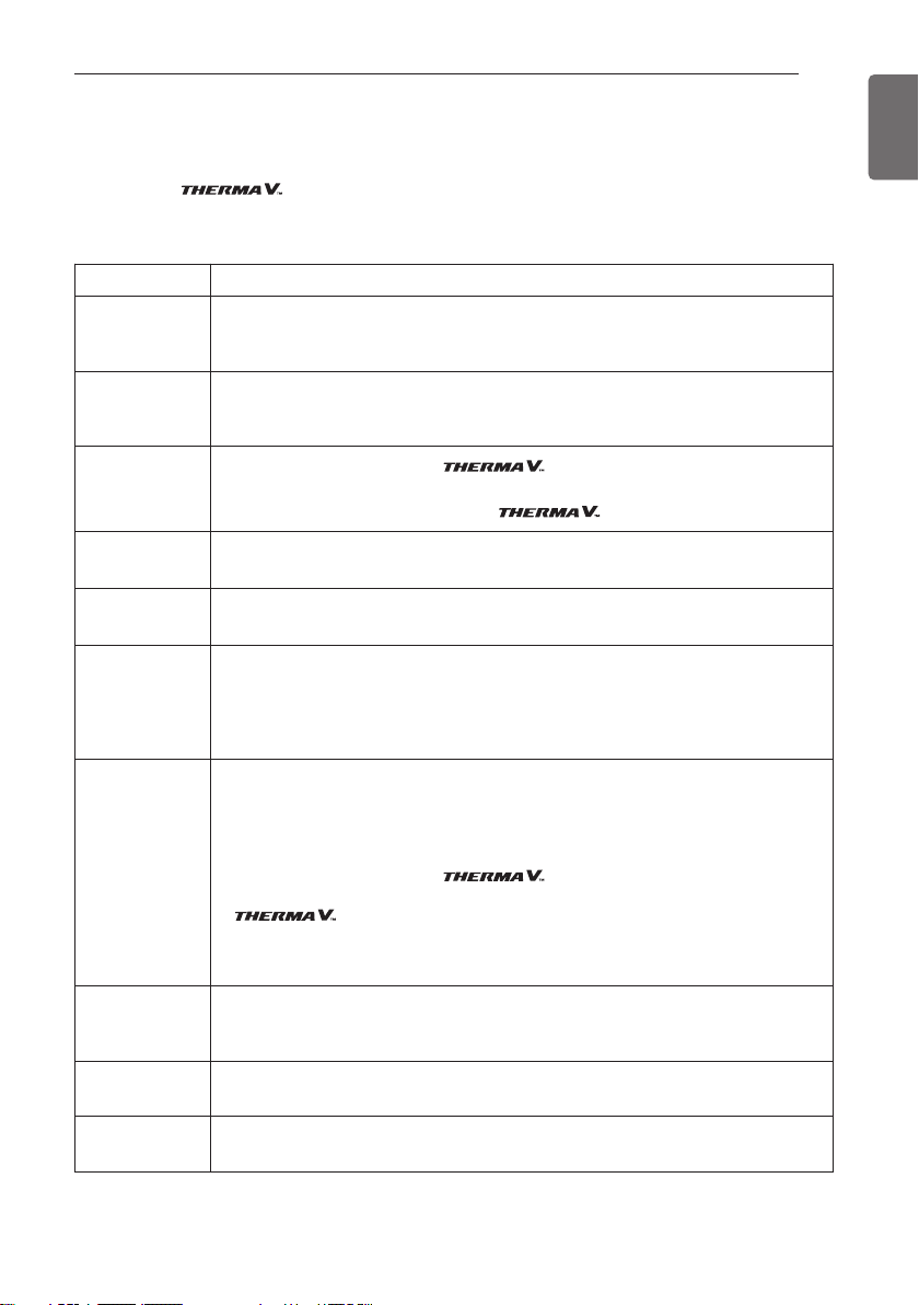
PREFACE
This installation manual is to present information and guide about understanding, installing,
and checking .
Your careful reading before installation is highly appreciated to make no mistake and to prevent
potential risks. The manual is divided into ten chapters. These chapters are classified according to
installation procedure. See the table below to get summarized information.
REMARK : ALL CONTENTS OF THIS MANUAL ARE SUBJECT TO CHANGE WITHOUT NOTICE.
TO GET THE LATEST INFORMATION, PLEASE VISIT LG ELECTRONICS WEB SITE.
Chapters Contents
Chapter 1
• Warning and Caution concerned with safety.
• This chapter is directly related with human safety. We strongly recommend reading this
chapter carefully.
Chapter 2
• Items Inside product Box
• Before starting installation, please make it sure that all parts are found inside the product
box.
Chapter 3
• Fundamental knowledge about
• Model identification, accessories information, cycle diagram, parts and dimensions, etc.
• This chapter is important to understand
Chapter 4
• Installation about the outdoor unit.
• Installation location, constraints on installation site, etc
Chapter 5
• Installation about the indoor unit.
• Installation location, constraints on installation site, etc
Chapter 6
• How to perform piping and wiring at the outdoor unit.
• Refrigerant pipe connection between the indoor unit and the outdoor unit.
• Water pipe connection between the indoor unit and outdoor unit.
• Electrical wiring at the outdoor unit.
Chapter 7
• How to perform piping (for water) and wiring at the indoor unit.
• Water pipe connection between the indoor unit and pre-built under floor water loop pipe.
• Electrical wiring at the indoor unit.
• System set-up and configuration.
• As many control parameters of is adjustable by control panel, deep
understanding about this chapter is required to secure the operation flexibility of
• For more detailed information, please read the separate operation manual to use control
panel and adjust control parameters.
Chapter 8
• Information about supported accessories
• Specification, Constraints, and wiring are described.
• Before purchasing accessories, please find supported specification to buy proper one.
Chapter 9
• Information about installation setting.
• DIP switch, service, installer setting etc.
Chapter 10
• Check points before starting operation are explained.
• Troubleshooting, maintenance, and error code list are presented to correct problems.

SAFETY INSTRUCTIONS
6
ENGLISH
WARNING
Installation
• Do not use a defective or underrated circuit breaker. Use this
appliance on a dedicated circuit.
- There is risk of fire or electric shock.
• For electrical work, contact the dealer, seller, a qualified
electrician, or an Authorized Service Center.
- There is risk of fire or electric shock.
!
Read the precautions in this
manual carefully before
operating the unit.
This appliance is filled with
flammable refrigerant (R32)
This symbol indicates that
the Operation Manual should
be read carefully.
This symbol indicates that a
service personnel should be
handling this equipment with
reference to the Installation
Manual.
SAFETY INSTRUCTIONS
WARNING
This indicates that the failure to follow the instructions can
cause serious injury or death.
CAUTION
This indicates that the failure to follow the instructions can
cause the minor injury or damage to the product.
This symbol is displayed to indicate matters and
operations that can cause risk. Read the part with this
symbol carefully and follow the instructions in order to
avoid risk.
!
!
!
The following safety guidelines are intended to prevent
unforeseen risks or damage from unsafe or incorrect operation
of the appliance. The guidelines are separated into ‘WARNING’
and ‘CAUTION’ as described below.

7
SAFETY INSTRUCTIONS
ENGLISH
• Always ground the unit.
- There is risk of fire or electric shock.
• Install the panel and the cover of control box securely.
- There is risk of fire or electric shock.
• Always install a dedicated circuit and breaker.
-
Improper wiring or installation may cause fire or electric shock.
• Use the correctly rated breaker or fuse.
- There is risk of fire or electric.
• Do not modify or extend the power cable.
- There is risk of fire or electric shock.
• Do not install, remove, or reinstall the unit by yourself
(customer).
- There is risk of fire, electric shock, explosion, or injury
• For antifreeze, always contact the dealer or an authorized
service center.
- Almost the antifreeze is a toxic product.
• For installation, always contact the dealer or an authorized
Service Center.
- There is risk of fire, electric shock, explosion, or injury.
• Do not install the unit on a defective installation stand.
- It may cause injury, accident, or damage to the unit.
• Be sure the installation area does not deteriorate with age.
- If the base collapses, the unit could fall with it, causing
property damage, unit failure, and personal injury.
• Do not install the water pipe system as Open loop type.
- It may cause failure of unit.
• Use a vacuum pump or inert (nitrogen) gas when doing
leakage test or purging air. Do not compress air or oxygen and
do not use flammable gases.
- There is the risk of death, injury, fire or explosion.
• Make sure the connected condition of connector in product
after maintenance.
- Otherwise, it may cause product damage.
• Do not touch leaked refrigerant directly.
- There is risk of frostbite.

8
SAFETY INSTRUCTIONS
ENGLISH
• Copper in contact with refrigerants shall be oxygen-free or
deoxidized, for example Cu-DHP as specified in EN 12735-1
and EN 12735-2.
• Compliance with national gas regulations shall be observed.
• Refrigerant tubing shall be protected or enclosed to avoid
damage.
• The installation of pipe-work shall be kept to a minimum.
• A brazed, welded, or mechanical connection shall be made
before opening the valves to permit refrigerant to flow
between the refrigerating system parts. A vacuum valve shall
be provided to evacuate the interconnecting pipe and/or any
uncharged refrigerating system part.
•
Any person who is involved with working on or breaking into a
refrigerant circuit should hold a current valid certificate from an
industry-accredited assessment authority, which authorises
their competence to handle refrigerants safely in accordance
with an industry recognised assessment specification.
• Do not use means to accelerate the defrosting process or to
clean, other than those recommended by the manufacturer.
• Do not pierce or burn.
• Be aware that refrigerants may not contain an odour.
• Dismantling the unit, treatment of the refrigerant oil and
eventual parts should be done in accordance with local and
national standards.
• Flexible refrigerant connectors (such as connecting lines
between the indoor and outdoor unit) that may be displaced
during normal operations shall be protected against mechanical
damage.
• Pipe-work shall be protected from physical damage.
• Mechanical connections (mechanical connectors or flared
joints) shall be accessible for maintenance purposes.
Operation
• Take care to ensure that power cable could not be pulled out
or damaged during operation.
- There is risk of fire or electric shock.

SAFETY INSTRUCTIONS
9
ENGLISH
• Do not place anything on the power cable.
- There is risk of fire or electric shock.
• Do not plug or unplug the power supply plug during operation.
- There is risk of fire or electric shock.
• Do not touch (operate) the unit with wet hands.
- There is risk of fire or electric shock.
• Do not place a heater or other appliances near the power
cable.
- There is risk of fire or electric shock.
• Do not allow water to run into electric parts.
- There is risk of fire, failure of the unit, or electric shock.
• Do not store or use flammable gas or combustibles near the
unit.
- There is risk of fire or failure of unit.
• Do not use the unit in a tightly closed space for a long time.
- It may cause damage to the unit.
• When flammable gas leaks, turn off the gas and open a
window for ventilation before turning the unit on.
- There is risk of explosion or fire.
• If strange sounds, or smell or smoke comes from unit, turn the
breaker off or disconnect the power supply cable.
- There is risk of electric shock or fire.
• Stop operation and close the window in storm or hurricane. If
possible, remove the unit from the window before the
hurricane arrives.
- There is risk of property damage, failure of unit, or electric
shock.
• Do not open the front cover of the unit while operation. (Do
not touch the electrostatic filter, if the unit is so equipped.)
- There is risk of physical injury, electric shock, or unit failure.
• Do not touch any electric part with wet hands. you should be
power off before touching electric part.
- There is risk of electric shock or fire.
• Do not touch refrigerant pipe and water pipe or any internal
parts while the unit is operating or immediately after operation.
- There is risk of burns or frostbite, personal injury.

10
SAFETY INSTRUCTIONS
ENGLISH
• If you touch the pipe or internal parts, you should be wear
protection or wait time to return to normal temperature.
- Otherwise , it may cause burns or frostbite, personal injury.
• Turn the main power on 6 hours ago before the product
starting operation.
- Otherwise, it may cause compressor damage.
• Do not touch electric parts for 10 minutes after main power
off.
- There is risk of physical injury, electric shock.
• The inside heater of product may operate during stop mode. It
is intended to protect the product.
• Be careful that some part of the control box are hot.
- There is risk of physical injury or burns.
• When the unit is soaked (flooded or submerged), contact an
Authorized Service Center.
- There is risk of fire or electric shock.
• Be cautious that water could not be poured to the unit directly.
- There is risk of fire, electric shock, or unit damage.
• Ventilate the unit from time to time when operating it together
with a stove, etc.
- There is risk of fire or electric shock.
• Turn the main power off when cleaning or maintaining the unit.
- There is risk of electric shock.
• Take care to ensure that nobody could step on or fall onto the
unit.
- This could result in personal injury and unit damage.
• If the unit is not used for long time, we strongly recommend
not to switch off the power supply to the unit.
- There is risk of water freezing.
• The appliance shall be stored in a well-ventilated area where
the room size corresponds to the room area as specified for
operation.
• The appliance shall be stored in a room without continuously
operating open flames (for example an operating gas
appliance) and ignition sources (for example an operating
electric heater).

11
SAFETY INSTRUCTIONS
ENGLISH
• The appliance shall be stored so as to prevent mechanical
damage from occurring.
• Servicing shall only be performed as recommended by the
equipment manufacturer. Maintenance and repair requiring the
assistance of other skilled personnel shall be carried out under
the supervision of the person competent in the use of flammable
refrigerants.)
• When mechanical connectors are reused indoors, sealing parts
shall be renewed. When flared joints are reused indoors, the
flare part shall be re-fabricated.
• Periodic(more than once/year) cleaning of the dust or salt
particles stuck on the heat exchangers by using water.
• Keep any required ventilation openings clear of obstruction.
CAUTION
Installation
• Always check for gas (refrigerant) leakage after installation or
repair of unit.
- Low refrigerant levels may cause failure of unit.
• Keep level even when installing the unit.
- To avoid vibration or water leakage.
• Use two or more people to lift and transport the unit.
- Avoid personal injury.
• In order to avoid a hazard due to inadvertent resetting of the
thermal cut-out, this appliance must not be supplied through
an external switching device, such as a timer, or connected to
a circuit that is regularly switched on and off by the utility.
• Do not install the unit in potentially explosive atmospheres.
• The water may drip from the discharge pipe of the pressurerelief device and that this pipe must be left open to the
atmosphere.
• The pressure-relief device is to be operated regularly to
remove lime deposits and to verify that it is not blocked.
• A discharge pipe connected to the pressure-relief device is to
be installed in a continuously downward direction and in a
frost-free environment.
!

12
SAFETY INSTRUCTIONS
ENGLISH
Operation
• Do not use the unit for special purposes, such as preserving
foods, works of art, etc.
- There is risk of damage or loss of property.
• Use a soft cloth to clean. Do not use harsh detergents,
solvents, etc.
- There is risk of fire, electric shock, or damage to the plastic
parts of the unit.
• Do not step on or put anything on the unit.
- There is risk of personal injury and failure of unit.
• Use a firm stool or ladder when cleaning or maintaining the
unit.
- Be careful and avoid personal injury.
• Do not turn on the breaker or power under condition that front
panel cabinet, top cover, control box cover are removed or
opened.
- Otherwise it may cause fire, electric shock, explosion or
death.
• The appliance shall be disconnected from its power source
during service and when replacing parts.
• Means for disconnection must be incorporated in the fixed
wiring in accordance with the wiring rules.
• The Installation kit supplied with the appliance are to be used
and that old Installation kit should not be reused.
• If the supply cord is damaged, it must be replaced by the
manufacturer, its service agent or similarly qualified persons in
order to avoid a hazard. Installation work must be performed in
accordance with the national wiring standards by authorized
personnel only.
• This equipment shall be provided with a supply conductor
complying with the national regulation.
• The instructions for service to be done by specialized
personnel, mandated by the manufacturer or the authorized
representative may be supplied in only one Community
language which the specialized personnel understand.

13
SAFETY INSTRUCTIONS
ENGLISH
• This appliance is not intended for use by persons (including
children) with reduced physical, sensory or mental capabilities
or lack of experience and knowledge, unless they have been
given supervision or instruction concerning use of the
appliance by a person responsible for their safety. Children
should be supervised to ensure that they do not play with the
appliance.

14
INSTALLATION PART
ENGLISH
(For Split IWT)
INDOOR UNIT BOX
Thank you for choosing LG Electronics Air-to-Water Heat Pump
Before starting installation, please make it sure that all parts are found inside the product box.
INSTALLATION PART
Item Image Quantity
Outdoor Unit
U36A Chassis
1
Damper 4
Drain Cap 2
Drain Nipple 1
OUTDOOR UNIT BOX
Item Image Quantity
Indoor Unit 1
Installation
Manual
1
Owner's /
Installation
manual
1
Item Image Quantity
Shut-off valve 1
Shut-off valve
with integrated
strainer
1
Gasket (G1”)
2
Gasket (G3/4”)
3

15
INSTALLATION PART
ENGLISH
Item Image Quantity
Shut-off valve 1
Shut-off valve
with integrated
strainer
1
Gasket (G1”)
4
Gasket (G3/4”)
3
Item Image Quantity
Indoor Unit 1
Installation
Manual
1
Owner's /
Installation
manual
1
(For Hydrosplit IWT)
INDOOR UNIT BOX
OUTDOOR UNIT BOX
Item Image Quantity
Outdoor Unit
U60A Chassis
1
Drain Cap 4
Drain Nipple 1
Strainer 1
Damper 4

16
INSTALLATION PART
ENGLISH
INSTALLATION TOOLS
Figure Name Figure Name
Screw driver Ohmmeter
Electric drill Hexagonal wrench
Measuring tape, Knife Ammeter
Hole core drill Leak detector
Spanner
Thermometer,
Horizontal meter
Torque wrench Flaring tool set
Manifold Gauge Vacuum Pump

17
GENERAL INFORMATION
ENGLISH
GENERAL INFORMATION
With advanced inverter technology, is suitable for applications like under floor
heating, under floor cooling, and hot water generation. By Interfacing to various accessories user
can customize the range of the application.
In this chapter, general information of is presented to identify the installation
procedure. Before beginning installation, read this chapter carefully and find helpful information
on installation.
Model Information
Factory Model Name
Outdoor unit (For Split IWT)
Z HUW 0 9 6 A 0
Series Number
Function
A : General heating heat pump
Electrical ratings
6 : 1 phase 220-240 V~ 50 Hz
Heating Capacity
05 : 5 kW 07 : 7 kW 09 : 9 kW
Model Type
W : Inverter Heat Pump
Classification
U : Outdoor Unit
ZH : Air-to-Water-Heat Pump for R32
Outdoor unit (For Hydrosplit IWT)
Z HBW 1 6 8 B 0
Series Number
Function
B : Hydrosplit Type
Electrical ratings
6 : 1 phase 220-240 V~ 50 Hz
8 : 3 phase 380-415 V~ 50 Hz
Heating Capacity
12 : 12 kW 14 : 14 kW 16 : 16 kW
Model Type
W : Inverter Heat Pump
Classification
B : Monobloc
ZH : Air-to-Water-Heat Pump for R32

18
GENERAL INFORMATION
ENGLISH
Function
I : Split IWT
Y : Hydrosplit IWT
Z H N W 2 0 6 0 6 I 0
Heater Electrical ratings
6 : 1 phase 220-240 V~ 50 Hz
Water Tank Capacity
20 : 200L
Heater Capacity
06 : 6 kW
Model Type
W : Inverter Heat Pump
Classification
N : Indoor Unit
ZH : Air-to-Water-Heat Pump for R32
Series Number
Indoor unit
Buyer Model Name
Outdoor unit (For Split IWT)
09 M R U 4 4
Series Number
Chassis
U36A
Classification
U : Outdoor Unit
Refrigerant
R : R32
M : Middle Temperature
Electrical ratings
1 : 1Ø, 220-240 V AC 50 Hz
Heating Capacity
Ex) “05” : 5 kW, “07” : 7 kW, “09” : 9 kW
Classification
U : Outdoor Unit
H : Air to Water Heat Pump
1UH
- IWT : Integrated water tank Indoor unit

19
GENERAL INFORMATION
ENGLISH
Indoor unit
09 6 T N B 1
Series Number
Chassis (Platform)
B : DHW tank integrated Platform
Classification
N : Indoor Unit
Function
T : Split IWT
Y : Hydrosplit IWT
Heater Capacity
6 : 6 kW Heater
Heater Electrical ratings
1 : 1Ø, 220-240 V, 50 Hz
Heating Capacity
Ex) “09” : 9 kW
“16” : 16 kW
Classification
N : Indoor Unit
H : Air to Water Heat Pump
1NH
Outdoor unit (For Hydrosplit IWT)
H U163 M R B U 3 0
Series Number
Chassis
U60A
Classification
U : Outdoor unit
B : Hydrosplit Type
Refrigerant
R : R32
M : Middle Temperature
Electrical ratings
1 : 1Ø, 220-240 V~ 50 Hz
3 : 3Ø, 380-415 V~ 50 Hz
Heating capacity
Ex) 12 kW : “12”, 14 kW : “14”, 16 kW : “16”
U : Outdoor unit
Classification
H : Air to water Heat Pump
- IWT : Integrated water tank Indoor unit
- DHW : Domestic hot water

20
GENERAL INFORMATION
ENGLISH
*1 : tested under EN14511
(water temperature 30 °C ’ 35 °C at outdoor ambient temperature 7 °C / 6 °C)
*2 : tested under EN14511
(water temperature 23 °C ’ 18 °C at outdoor ambient temperature 35 °C / 24 °C)
h All appliances were tested at atmospheric pressure.
How to find additional model information
Energy Labels and Product Fiches for all possible combinations can be found at
https://www.lg.com/global/support/cedoc/cedoc.
Search for outdoor unit name in cedoc page.
Model Name
Built-In
Electric
Heater(kW)
Capacity
Power Source
(Unit)
Type
Refrigerant
Outdoor Unit Indoor Unit
Heating
(kW)*
1
Cooling
(kW)*
2
Phase (Ø)
Capacity (kW)
Tank Capacity (L)
Split
R32
1
5
200
1Ø 2 (2)
1Ø 4 (2+2)
3Ø 6 (2+2+2)
5.5 5.5
220-240 V
50 Hz
7 7.0 7.0
9 9.0 9.0
Hydrosplit
1
12 12.0 12.0
220-240 V
50 Hz
14 14.0 14.0
16 16.0 16.0
3
12 12.0 12.0
380-415 V
50 Hz
14 14.0 14.0
16 16.0 16.0
Model name and related information

21
GENERAL INFORMATION
ENGLISH
Parts and Dimensions
Indoor unit (For Split IWT) : External
(unit : mm)
Description
1 SAE 5/8" Refrigerant gas pipe
2 SAE 3/8" Refrigerant liquid pipe
3 G3/4" Domestic hot water outlet
4 G3/4" Domestic cold water Inlet
5 G3/4" DHW Re-circulation
6 G1" Heating circuit inlet
7 G1" Heating circuit outlet
8 Built-in Remote controller
9 Electrical conduits
12 3 45 67
1812 87
65 108 63 63 108 65
198
9
551
30
8
1249
542
685
601

22
GENERAL INFORMATION
ENGLISH
(unit : mm)
Indoor unit (For Split IWT) : Internal
Description
No Item No Item
1
Domestic hot water tank
10
DHW water pump
2
Electric heater
11
DHW strainer
3
Flow sensor
12
Main water pump
4
3-way-valve DHW / Heating
13
DHW Expansion vessel (Accessory)
5
Pressure gauge
14
Control box
6
Expansion vessel for Heating
15
Air vent
7
Magnesium anode
16
Drain cock
8
DHW tank sensor
17
Conduits for electrical wiring
9
Plate-heat-exchanger (Water/DHW)
18 Plate-heat-exchanger (Refrigerant/Water)
15
12
6
9
9
10
11
16
5
4
18
14
14
7
8
1
16
3
2

23
GENERAL INFORMATION
ENGLISH
Outdoor unit (For Split IWT) : External
Product Heating Capacity :
5 kW,7 kW,9 kW
U36A Chassis
(unit : mm)
No Name
1 Liquid-side Service Valve
2 Gas-side Service Valve
3 Air discharge Grille
Description
4-holes for anchor bolts
390
330
Supporter
834
809
165 165
620
950
390

24
GENERAL INFORMATION
ENGLISH
Indoor unit (For Hydrosplit IWT) : External
Description
1 G1” Inlet from outdoor unit
2 G1” Outlet to outdoor unit
3 G3/4" Domestic hot water outlet
4 G3/4" Domestic cold water Inlet
5 G3/4" DHW Re-circulation
6 G1" Heating circuit inlet
7 G1" Heating circuit outlet
8 Built-in Remote controller
9 Electrical conduits
(unit : mm)
30
1812
198
9
12 3 45 67
8
551
66 107 63 63 108 65
614
1249
542
685
601

25
GENERAL INFORMATION
ENGLISH
(unit : mm)
Indoor unit (For Hydrosplit IWT) : Internal
Description
No Item No Item
1
Domestic hot water tank
10
DHW water pump
2
Electric heater
11
DHW strainer
3
Flow sensor
12
Main water pump
4
3-way-valve DHW / Heating
13
DHW Expansion vessel (Accessory)
5
Water pressure sensor
14
Control box
6
Expansion vessel for Heating
15
Air vent
7
Magnesium anode
16
Drain cock
8
DHW tank sensor
17
Conduits for electrical wiring
9
Plate-heat-exchanger (Water/DHW)
O
F
E
M
N
Q
A
I
G
H
P
J
K
P
D
L
C
B

26
GENERAL INFORMATION
ENGLISH
Outdoor unit (For Hydrosplit IWT) : External
No Name
1 Entering Water Pipe
2 Leaving Water Pipe
3 Air discharge Grille
Description
Product Heating Capacity :
12 kW, 14 kW, 16 kW
U60A Chassis
(unit : mm)
165 619
330
390
360
4-holes for anchor bolts (M10)
3
834
24
165 166
619
950
2
1
405
137
390

27
GENERAL INFORMATION
ENGLISH
Control Parts
Control Box : Indoor Unit (For Split IWT)
Description
No Name Remark
1 Main PCB
The main PCB(Printed Circuit Board) controls the functioning
of the unit
2 Terminal blocks The terminal blocks allow easy connection of field wiring
3
Safety thermostat for
Electric heater
The safety thermostat protects the backup heater against
overload or short circuit
4 Electric heater Relay -
5 Holes for dry contact -
3
1
4
5
2

28
GENERAL INFORMATION
ENGLISH
Control Box : Indoor Unit (For Hydrosplit IWT)
Description
No Name Remark
1 Main PCB
The main PCB(Printed Circuit Board) controls the functioning
of the unit
2 Terminal blocks The terminal blocks allow easy connection of field wiring
3
Safety thermostat for
Electric heater
The safety thermostat protects the backup heater against
overload or short circuit
4 Electric heater Relay -
5 Holes for dry contact -
3
1
5
4
2

29
GENERAL INFORMATION
ENGLISH
Control Panel
Operation display window Operation and Settings status display
Back button When you move to the previous stage from the menu’s setting stage
Up/down/left/right button When you change the menu’s setting value
OK button When you save the menu’s setting value
On/Off button When you turn ON/OFF the AWHP
Operation display
window
Back button
Up/Down/Left/Right
Button
OK
On/Off Button
OK Button
30
GENERAL INFORMATION
ENGLISH
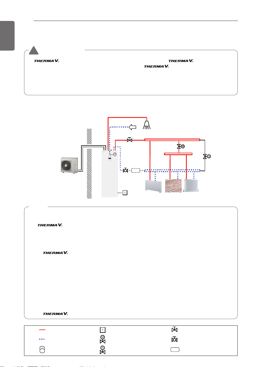
CASE 1 : Connecting Heat Emitters for Heating and Cooling & DHW
(Under floor loop, Fan Coil Unit, Radiator, and Domestic hot water)
Typical Installation Example
CAUTION
!
If is installed with pre-existing boiler, the boiler and should not be
operated together. If entering water temperature of is above 55 °C, the system
will stop operation to prevent mechanical damage of the product. For detailed electric wiring
and water piping, please contact authorized installer.
Some installation scenes are presented for example. As these scenes are conceptual figures,
installer should optimize the installation scene according to the installation conditions.
Outdoor Indoor
Outdoor Unit
Indoor Unit
Floor
heating loop
Fan coil unit
Radiator
M / F
City water
Domestic hot water
NOTE
• Room thermostat
- Type of thermostat and specification should be complied with chapter 8 and chapter 9 of
installation manual.
• 2way valve
- It is important to install 2way valve to prevent dew condensation on the floor and radiator while
cooling mode.
- Type of 2way control valve and specification should be complied with chapter 8 and chapter 9
of installation manual.
- 2way valve should be installed at the supply side of the collector.
• By-pass valve
- To secure enough water flow rate, by-pass valve should be installed at the collector.
- By-pass valve should guarantee minimum water flow rate in any case. Minimum water flow
rate is described in water pump characteristics curve.
• DHW Expansion vessel
- The cold DHW connection must be fitted with an expansion vessel suitable for drinking water.
The selection and installation must be in accordance with the standard DIN 4807 T5.
- An expansion vessel of 8 l volume that can be integrated into the unit is available as
accessory [OSHE-12KT]. the installation method of Expansion vessel can be found in chapter 8
of installation manual.
High Temperature Room Thermostat (Field supply)
2way valve (Field supply)
By-pass valve(Field supply)
Low Temperature
DHW Expansion vessel
(Accessory)
Magnetic Filter (Recommended)
Shut-off valve with strainer
Shut-off valve
M / F

31
GENERAL INFORMATION
ENGLISH
CASE 2 : Connecting mixed Circuit
Outdoor Indoor
Outdoor Unit
Indoor Unit
M / F
City water
Domestic
hot water
Floor heating loop
Mixing circuit temp. sensor
Mix
Mix Kit
[Circuit 1] Direct Circuit
[Circuit 2] Mixing Circuit
Floor heating loop
Radiator Radiator
Buffer
Tank
High Temperature Room Thermostat (Field supply)
Pump(Field supply)
By-pass valve(Field supply)
Pressure Regulation valve
(Field supply)
Low Temperature
Buffer tank (Accessory)
Expansion vessel (Accessory)
Magnetic Filter (Recommended)
Shut-off valve with strainer
Mix Kit (Field supply)
Shut-off valve
M / F
NOTE
• Mix Kit
- You can install it when you want to set the temperature of two rooms individually
- When heating, Circuit 2 can not be higher than Circuit 1.
- When cooling, Circuit 2 can not be lower than Circuit 1.
- The types and specifications of the Mix Kit are to comply with chapter 8 and chapter 9 of
the Installation Manual.
• Buffer Tank
- A Buffer tank of 40 l volume that can be integrated into the unit is available as accessory
[OSHB-40KT].
- the installation method of Buffer tank can be found in chapter 8 of installation
manual.
• External pump
- For Hydrosplit IWT, the location of the external pump may vary depending on the installer
settings.

32
GENERAL INFORMATION
ENGLISH
CASE 3 : Connecting 3rdParty Boiler
Outdoor Indoor
Outdoor Unit
Indoor Unit
M / F
City water
Domestic
hot water
Buffer
Tank
Floor
heating loop
Boiler
Floor
heating loop
Floor
heating loop
High Temperature Room Thermostat (Field supply)
By-pass valve(Field supply)
Air vent (Field supply)
2way valve (Field supply)
Low Temperature
Buffer tank (Accessory)
Expansion vessel (Accessory)
Aquastat V/V
Pump(Field supply)
Shut-off valve
Magnetic Filter (Recommended)
Check valve
M / F
Shut-off valve with strainer
NOTE
• 3rdparty Boiler
- You can control the boiler automatically and manually by comparing the outside
temperature and the set temperature.
For Hydrosplit IWT
Hydrosplit IWT has the same installation scene as Split IWT, Except for connection with outdoor
unit.
- The outdoor unit and the indoor unit are connected by water pipes.
- To protect the product, be sure to install a strainer on the outdoor unit water inlet pipe.
- Install an air vent(Field supply) on the highest point of the water connection between outdoor
and indoor unit.
- Make sure that the water pipes are protected from freezing in case of heat pump failure or
power outage (e.g. Anti-freeze valve, that drains the water if temperature drops too much).
Outdoor Indoor
Outdoor Unit
Indoor Unit
Outdoor Indoor
Outdoor Unit
Indoor Unit
Strainer
(Field Supply)
(For Split IWT) (For Hydrosplit IWT)

33
GENERAL INFORMATION
ENGLISH
Cycle Diagram (For Split IWT)
Description
Category Symbol Meaning PCB Connector
Refrigerant
side
S1 Compressor-suction pipe temperature sensor CN_SUCTION
S2 Inlet IHEX temperature sensor CN_VI_IN
S3 Outdoor air temperature sensor CN_AIR
S4 Outdoor-HEX temp. sensor CN_C_PIPE
S5 Compressor-discharge pipe temperature sensor CN_DISCHARGE
S6 Outdoor-HEX middle temp. sensor CN_MID
S9 PHEX gas temp. sensor CN_PIPE/OUT
S10 PHEX liquid temp. sensor CN_PIPE/IN
EEV1 Electronic Expansion Valve (Heating) CN_EEV1(WH)
EEV3 Electronic Expansion Valve (Injection) CN_EEV3(YL)
Water Side
S11 Inlet water temperature sensor
CN_TH3S12 Outlet water temperature sensor
S13 Electric heater outlet sensor
S14 DHW tank temperature sensor CN_TH4
S17 Flow sensor CN_F_METER
A1 Main water pump
CN_MOTOR1
CN_W_PUMP_A
A16 DHW Water pump CN_W_PUMP_B
A5 3Way Valve CN_3WAY_A
A8 Electric backup heater CN_E_HEAT_A
<Refrigerant Side> <Water Side>
: Cooling
: Heating
S3
Pressure
Sensor
S6
S4
EEV1
S2
EEV3
(Inj.EEV)
Pressure
Switch
Accumulator
S1
Muffler
S5
Inv.Comp
<Outdoor Unit>
S9
S10
Drain pan
S14
Domestic
Water Out
DHW Tank
S12
S11
Domestic
Water In
Air Vent
DHW
Expansion
Vessel
Re-circulation
Drain/Fill
Cock
S17
A1
Pressure
Gauge
A8
Drain/Fill Cock
DHW
Safety
Valve
Drain Cock
WaterInWater
Shut-off
Valve
With
Strainer
S13
Expansion
Vessel
Safety
Valve
Drain/Fill
Cock
DHW PHEX
A16
DHW Strainer
<Indoor Unit>
A5
M
Vent
Air
Out
Shut-off
Valve

34
GENERAL INFORMATION
ENGLISH
Cycle Diagram (For Hydrosplit IWT)
Description
Category Symbol Meaning PCB Connector
Refrigerant
side
S1 PHEX liquid temperature sensor CN_PIPE_IN
S2 Outdoor-HEX middle temperature sensor CN_MID
S3 Compressor-discharge pipe temperature sensor CN_DISCHARGE
S4 Compressor-suction pipe temperature sensor CN_SUCTION
S5 Outdoor-HEX temperature sensor CN_C_PIPE
S6 Outdoor air temperature sensor CN_AIR
S7 Compressor-injection pipe temperature sensor CN_VI_IN
EEV1 Electronic Expansion Valve (Heating/Cooling) CN_EEV1
EEV2 Electronic Expansion Valve (Injection) CN_EEV_MAIN
Water Side
S11 Inlet water temperature sensor
CN_WATER_IN_BL
CN_WATER_OUT_BL
S12 Outlet water temperature sensor
S13 Electric heater outlet sensor CN_TH3
S14 DHW tank temperature sensor CN_TH4
S17 Flow sensor CN_F_SENSOR
S19 Water pressure sensor CN_H20_PRESS
A1 Main water pump
CN_MOTOR1
CN_PUMP_A1
A16 DHW Water pump CN_PUMP_A4
A5 3Way Valve CN_3WAY_A
A8 Electric backup heater CN_TANK_HEATER
<Refrigerant Side> <Water Side>
: Cooling
: Heating
S6
Pressure
S2
S5
EEV1
S7
EEV2
(Inj.EEV)
Pressure
Switch
Accumulator
S4
Sensor
Muffler
S3
Inv.Comp
S1
<Outdoor Unit>
(Field Supply)
Air
Shut-off
Vent
Valve
With
Strainer
Shut-off
Valve
S12
Strainer
S11
Drain pan
S14
Domestic
Water Out
DHW Tank
Domestic
Water In
A1
Re-circulation
S17
DHW
Expansion
Vessel
Drain/Fill
Cock
DHW
Safety
Valve
Pressure
Sensor
A8
Drain/Fill
Cock
Expansion
Vessel
Drain/Fill
Cock
DHW Strainer
Drain Cock
WaterInWater
Shut-off
Valve
With
Strainer
S19
S13
Safety
Valve
DHW PHEX
A16
<Indoor Unit>
Out
Shut-off
Valve
A5
M
Air
Vent

35
GENERAL INFORMATION
ENGLISH
Piping Diagram (For Split IWT)
CAUTION
!
The diagram represents a schematic overview of the required system components and their
location. It does not include all necessary components and safety devices according to DIN
EN 12828, and eventually required equipment for maintenance and service. Local/national
regulation needs to be followed! Subject to technical changes.
The following diagram shows an exemplary installation scene. For other examples, please ask
your local LG Partner for support.
LG supply
① Outdoor unit [HU0X1MR.U44]
② Indoor unit [HN0916T.NB1]
③ DHW expansion vessel (8l) [OSHE-12KT]
④ Buffer tank (40l) [OSHB-40KT]
⑤ WIFI modem [PWFMDD200]
⑥ Extension cable(10m) [PWYREW000]
⑦ Room air sensor [PQRSTA0]
Outdoor Indoor
3
2
1
a
5
6
4
7
b
Refrigerant gas (5/8”)
Refrigerant liquid (3/8”)
Heating water - outlet
Heating water - inlet
Domestic hot water(DHW)
Domestic cold water
DHW re-circulation
a. DHW Re-circulation pump (self-controlled)
b. External circulation (with buffer only)

36
GENERAL INFORMATION
ENGLISH
Piping Diagram (For Hydrosplit IWT)
CAUTION
!
The diagram represents a schematic overview of the required system components and their
location. It does not include all necessary components and safety devices according to DIN
EN 12828, and eventually required equipment for maintenance and service. Local/national
regulation needs to be followed! Subject to technical changes.
The following diagram shows an exemplary installation scene. For other examples, please ask
your local LG Partner for support.
LG supply
① Outdoor unit [HU1XXMRB.U30]
② Indoor unit [HN1616Y.NB1]
③ DHW expansion vessel (8l) [OSHE-12KT]
④ Buffer tank (40l) [OSHB-40KT]
⑤ WIFI modem [PWFMDD200]
⑥ Extension cable(10m) [PWYREW000]
⑦ Room air sensor [PQRSTA0]
Outdoor Indoor
3
2
1
Strainer
a
5
6
4
7
b
Heating water - Hot
Heating water - Cold
Domestic hot water(DHW)
Domestic cold water
DHW re-circulation
a.DHW Re-circulation pump (self-controlled)
b.External circulation (with buffer only)

37
GENERAL INFORMATION
ENGLISH
The design of the system must be planned and executed by a professional HVAC installer
according to European and National regulations and Standards. The following points should be
explicitly taken into account.
CAUTION
!
• Make sure that the minimum water flow rate as given in the Specification is never
undercut. Install a Hydraulic separator, buffer tank connected in parallel to the heating
system or a bypass valve with sufficient dimension!
• If the heat pump is installed together with an external boiler, the devices should not be
operated at the same time. If operated in parallel, take appropriate measures to prevent
hot water from entering the heat pump. If the temperature is higher than the operating
range of the heat pump it can lead to malfunctions or damage the product.
• When using an Underfloor heating system:
- Respect the maximum temperature as given by the manufacturer. An independent
overheat cut-off device is recommended.
- When using underfloor cooling, the adequacy of the underfloor system must be
approved by the manufacturer.
• General recommendations for Cooling operation:
- Use diffusion resistant insulation.
- Carefully agglutinate the joints of the insulation. If air can enter between pipe and
insulation, it will get wet and useless.
- Install a 2-way-valve to block parts of the distribution system that are not designed for
cooling. Refer to chapter 3.4.13 for information how to connect the valve.
- Install external dew point monitor (relay) in combination with dry contact. The relative
humidity shall not exceed 65%.
- Use reversible control valves (heating/cooling) for individual room control (e.g. underfloor
thermostats).
• If the unit is connected to an old piping system:
- A magnetic filter should be installed in the return pipe to protect the unit from particles
that can block the heat-exchanger and damage the unit.
- If pipe diameter is too small (<1 inch) or the pipe diameter is narrowed by scaling, it can
lead to flow noise and cause problems due to limitation of water flow rate. Install a
parallel buffer tank / hydronic separator.
• Prevention of noise must be taken into account when designing the installation.
- Calculate the sound emission and respect local laws and regulations, before installing the
unit.
- Do not install the outdoor unit at an exposed position (on top of garage, high at the wall)
- If possible, prevent installation in a corner of the house or close to other surfaces that
concentrates the sound.
- Prevent structure-borne noise. De-couple the pipes. Install the units on foundations decoupled from the building. Use dampers.
• Make sure that enough heat is available for Defrosting. If that cannot be ensured by the
heating system, install a buffer tank.
• Carefully follow the instructions regarding Condensate drainage and frost-free installation
of pipes.
System planning and preparation

38
INSTALLATION OF OUTDOOR UNIT
ENGLISH
Minimum service space
(unit : mm)
Drill a Hole in the Wall (For Split)
- If making a hole to the wall is required to connect pipe between the indoor unit and the outdoor
unit, please follow below descriptions.
Drill the piping hole with a Ø 70 mm hole core drill.
Piping hole should be slightly slant to the outdoor side to prevent raindrop into indoor side.
300
Fence or
obstacles
700
300
600
Sunroof
INSTALLATION OF OUTDOOR UNIT
The outdoor unit of is installed outside to exchange heat with ambient air.
Therefore, it is important to secure proper space around the outdoor unit and care for specific
external conditions.
This chapter presents a guide to install the outdoor unit, make a route to connect with the indoor,
and what to do when installed around seaside.
Conditions where Outdoor Unit is Installed
- If a sunroof is built over the unit to prevent direct sunlight or rain exposure, make sure that heat
radiation from the heat exchanger is not restricted.
- Ensure that the spaces indicated by arrows around front, back and side of the unit.
- Do not place animals and plants in the path of the warm air.
- Take the weight of the outdoor unit into account and select a place where noise and vibration
are minimum.
- Select a place so that the warm air and noise from the outdoor unit do not disturb neighbors.
Wall
5~7 mm
Indoor Outdoor

39
INSTALLATION OF OUTDOOR UNIT
ENGLISH
Transporting the Unit
• When carrying the suspended unit, pass the ropes between legs of base panel under the unit.
• Always lift the unit with ropes attached at four points so that impact is not applied to the unit.
• Attach the ropes to the unit at an angle Ⓐ of 40° or less.
• Use only accessories and parts which are of the designated specification when installing.
Sub line
40º or less
Air outlet grille Intake hole
Always hold the unit by the corners, as holding
it by the side intake holes on the casing may
cause them to deform.
Corner
Handle
Forklift

40
INSTALLATION OF OUTDOOR UNIT
ENGLISH
CAUTION
!
Be very careful while carrying the product.
• Do not have only one person carry product if it is more than 20 kg.
• PP bands are used to pack some products. Do not use them as a mean for transportation
because they are dangerous.
• Do not touch heat exchanger fins with your bare hands. Otherwise you may get a cut in
your hands.
• Tear plastic packaging bag and scrap it so that children cannot play with it. Otherwise
plastic packaging bag may suffocate children to death.
• When carrying in Unit, be sure to support it at four points. Carrying in and lifting with
3-point support may make Outdoor Unit unstable, resulting in a fall.
• Use 2 belts of at least 8 m long.
• Place extra cloth or boards in the locations where the casing comes in contact with the
sling to prevent damage.
• Hoist the unit making sure it is being lifted at its center of gravity.

41
INSTALLATION OF OUTDOOR UNIT
ENGLISH
- In case, to install the outdoor unit on the seaside, set up a windbreak not to be exposed to the
sea wind.
- It should be strong enough like concrete to
prevent the sea wind from the sea.
- The height and width should be more than 150%
of the outdoor unit.
- It should be keep more than 700 mm of space
between outdoor unit and the windbreak for easy
air flow.
CAUTION
!
• AWHP should not be installed in areas where corrosive gases, such as acid or alkaline gas,
are produced.
• Do not install the product where it could be exposed to sea wind (salty wind) directly. It
can result corrosion on the product. Corrosion, particularly on the condenser and
evaporator fins, could cause product malfunction or inefficient performance.
• If outdoor unit is installed close to the seaside, it should avoid direct exposure to the sea
wind. Otherwise it needs additional anti-corrosion treatment on the heat exchanger.
Sea wind Sea wind
Sea wind
Windbreak
- Select a well-drained place.
Periodic ( more than once/year ) cleaning of the dust or salt particles stuck on the heat
exchanger by using water.
- If you can’t meet above guide line in the seaside installation, please contact your supplier for the
additional anti-corrosion treatment.
Seasonal wind and cautions in winter
• Sufficient measures are required in a snow area or severe cold area in winter so that product can be
operated well.
• Get ready for seasonal wind or snow in winter even in other areas.
• Install a suction and discharge duct not to let in snow or rain.
• Install the outdoor unit not to come in contact with snow directly. If snow piles up and freezes on the
air suction hole, the system may malfunction. If it is installed at snowy area, attach the hood to the
system.
• Install the outdoor unit at the higher installation console by 500 mm than the average snowfall (annual
average snowfall) if it is installed at the area with much snowfall.
• Where snow accumulated on the upper part of the Outdoor Unit by more than 100 mm, always
remove snow for operation.
- The height of H frame must be more than 2 times the snowfall and its width shall not exceed the
width of the product. (If width of the frame is wider than that of the product, snow may accumulate)
- Don't install the suction hole and discharge hole of the Outdoor Unit facing the seasonal wind.
Installation at Seaside
Selecting the location(Outdoor Unit)
- If the outdoor unit is to be installed close to the seaside, direct exposure to the sea wind should
be avoided. Install the outdoor unit on the opposite side of the sea wind direction.

42
INSTALLATION OF INDOOR UNIT
ENGLISH
INSTALLATION OF INDOOR UNIT
The indoor unit of is installed inside where terminal of under floor water pipe cycle
and refrigerant pipe from the outdoor unit are accessible at the same time.
In this chapter conditions for installation place is described. In addition, considerations when
installing accessories or 3
rd
party accessories are described, too.
Conditions where Indoor Unit is Installed
Specific conditions are required for installation place such as service space, condensate
drainage, water pipe length and height, total volume of water, adjusting expansion vessel, and
water quality.
General Considerations
Followings are should be considered before the installation of the indoor unit.
- The installation place should be free from outdoor weather conditions such as rain, snow, wind,
frost, etc.
- Choose the place where is water-resistant or good drainage.
- Service space should be secured.
- No flammable materials around the indoor unit.
- Mice can not be appeared to prevent entering the indoor unit or attacking wires.
- Do not place anything in front of the indoor unit to ensure air circulation around the indoor unit.
- Do not locate anything under the indoor unit to be free from unexpected water out.
- In case of water pressure increasing to 3 bar or tank pressure increasing to 10 bar, water
drainage should be treated when water is drained by safety valve.
NOTICE
The installation location of the indoor unit must be dry and in the temperature range between
+10 ˚C and 40 ˚C, for a short period (up to 24h) also up to 55 °C.
WARNING
!
Do not block the venting openings on the backside of the unit! (For Split IWT)
CAUTION
!
The device must not be installed under pipelines because there is a possibility of condensate
forming. Ingress of water condensate can cause disturbances in the operation.

43
INSTALLATION OF INDOOR UNIT
ENGLISH
Minimum service space
(unit : mm)
NOTE
• Provide enough space for
servicing and air circulation. The
unit is designed to allow servicing
from front side. However, if it
becomes necessary to replace
components, a service area of
approximately 500 mm on the
right side, makes the task much
easier.
Transporting the Unit
CAUTION
!
• The device must be transported with transport
devices.
• Secure the device during transport to prevent damage.
• The device must not be stacked and other objects
must not be placed on it.
• Appropriate transport equipment must be used for
installing the device. Safety regulations and good
practice have to be applied.
• When lifting the unit, use the dedicated carrying
handles at bottom and backside of the product
• Tilt over the unit carefully with at least two persons
Service Space
- Ensure that the spaces indicated by
arrows around front, right, and top
side.
- Wider spaces are preferred for easy
maintenance and piping.
- If minimum service space is not
secured, air circulation can be troubled
and internal parts of the indoor unit
can be damaged by overheating.
500
(Recommended)
600
500
(Recommended)
300

44
INSTALLATION OF INDOOR UNIT
ENGLISH
①
②
③
Front Panel Removal
Step 1. After releasing a screw from the top the Indoor unit,
detach front panel ①.
Step 2. Tilt the front panel towards you ② and lift it ③ for
opening
Step 3. Before taking front panel off completely, disconnect
the cable of the remote controller ④.
CAUTION
!
After installation is completed, reconnect the cable of
remote controller.
Step 3. Before connecting any pipes, level the indoor unit
with supplied adjustable levelling feet.
CAUTION
!
• Attaching the hose for the condensate drain to the
sewer hose can cause corrosion of the appliance’s
internal components.
• The drain pipe must have an odor trap!
Connecting Condensate drainage
Step 1. Before the indoor unit’s final positioning, attach the
flexible Ø16 hose to the drainpipe, which has been
prepared in advance. Insert the drainage hose into
the drain ①, which leads to the sinkhole or storm
drain. Seal the gap with a suitable gasket.
Step 2. Then push the appliance to the wall ②.
①
②
④

45
INSTALLATION OF INDOOR UNIT
ENGLISH
- If the total refrigerant charge (mc) is in system ≥1.842 kg, additional minimum floor area requirements
is complied in the following flow chart.
Floor area requirement : Indoor unit (For Split IWT)
Determine :
• The total refrigerant charge in the
system, mc (kg)
• The room A area installed the appliance,
A
Room
(m2)
Calculate based on Table 1 :
• The maximum refrigerant charge allowed
for room A
max
(kg)
Determine :
• The adjacent room B area, B
Room
(m2)
Calculate based on Table 2 :
• The total minimum floor area required for
the total refrigerant charge mc, A
min
(m2)
Calculate based on Table 3 :
• The minimum opening area for natural
ventilation between room A and room B
according to the value of mcand A
Room
,
A
min
(m2)
The unit can be installed in
room A when the
following ventilation
requirements are fulfilled.
please contact your
local engineer /
dealer.
The unit can be installed in room A without
further room size or ventilation requirements.
m
max
≥ m
c
A
Room
+ B
Room≥Amin
Yes
Yes
No
No
Room A Room B
More
than
1.5m
A
Room
> 0.5 * AV
>
B
AV
min
min
Room

46
INSTALLATION OF INDOOR UNIT
ENGLISH
• Two ventilation openings, one at bottom, another at top, for ventilation purposes are made
between room A and room B.
• Bottom opening :
- Must comply to the minimum area requirement of AV
min
.
- Opening must be located 300mm from the floor.
- At least 50% of required opening area must be 200mm from the floor.
- The bottom of the opening shall not be higher than the point of release when the unit is
installed and must be situated 100mm above the floor.
- Must be as close as possible to the floor and lower than h
0
.
(h0=Installation height, The value of h0in this unit is considered as 1.2m)
• Top opening :
- The total size of the Top opening must be more than 50% of AV
min
- Opening must be located 1500mm above the floor.
• The height of the openings between the wall and floor which connect the rooms are not less
than 20 mm.
• Ventilation openings to the outside are NOT considered suitable ventilation openings (the user
can block them when it is cold).
Table 1 - Maximum refrigerant charge allowed in a room
Ventilation requirements
NOTE
• The value of "Release height (h0)“ in this unit is considered 1200 mm to comply to IEC
60335-2-40:2013 A1 2016 Clause GG2.
• For intermediate A
room
values, the value that corresponds to the lower A
room
value from the
table is considered. (If A
room
=10.5 m2, consider the value that corresponds to A
room
=10 m2.)
A
room
(m2)
Maximum refrigerant charge in a room
m
max
(kg)
Based on
h01.2 m
1 0.28
2 0.55
3 0.83
4 1.11
5 1.38
6 1.66
7 1.81
8 1.94
9 2.06
10 2.17
11 2.27
12 2.37
13 2.47
14 2.57
15 2.66
16 2.74
17 2.83
18 2.91
19 2.99
20 3.07
21 3.14

47
INSTALLATION OF INDOOR UNIT
ENGLISH
NOTE
• The value of "Release height (h0)“ in this
unit is considered 1200 mm to comply
to IEC 60335-2-40:2013
A1 2016 Clause GG2.
• For intermediate m
c
values, the value
that corresponds to the higher mcvalue
from the table is considered.
(If mc= 1.85 kg, the value that corresponds
to mc = 1.86 kg is considered.)
• Systems with total refrigerant charge
lower than 1.84 kg are not subjected to
any room area requirements.
• Charges above 3.10 kg are not allowed
in the unit.
Table 2 - Minimum floor area
25
24
23
22
21
20
19
18
17
16
15
14
13
12
11
10
9
8
7
6
5
4
3
2
1
0
1.5 2.0 2.5 3.0 3.5
Amin (m
2
)
mc (kg)
Total Ref.
Amount
mc(kg)
Minimum Floor Area
A
min
(m2)
Based on
h01.2 m
1.84 7.20
1.86 7.36
1.88 7.52
1.90 7.68
1.92 7.84
1.94 8.01
1.96 8.17
1.98 8.34
2.00 8.51
2.02 8.68
2.04 8.85
2.06 9.03
2.08 9.21
2.10 9.38
2.12 9.56
2.14 9.74
2.16 9.93
2.18 10.11
2.20 10.30
2.22 10.49
2.24 10.68
2.26 10.87
2.28 11.06
2.30 11.26
2.32 11.45
2.34 11.65
2.36 11.85
2.38 12.05
2.40 12.26
2.42 12.46
2.44 12.67
2.46 12.88
2.48 13.09
2.50 13.30
2.52 13.51
2.54 13.73
2.56 13.94
2.58 14.16
2.60 14.38
2.62 14.61
2.64 14.83
2.66 15.05
2.68 15.28
2.70 15.51
2.72 15.74
2.74 15.97
2.76 16.21
Total Ref.
Amount
mc(kg)
Minimum Floor Area
A
min
(m2)
Based on
h01.2 m
2.78 16.44
2.80 16.68
2.82 16.92
2.84 17.16
2.86 17.40
2.88 17.65
2.90 17.89
2.92 18.14
2.94 18.39
2.96 18.64
2.98 18.89
3.00 19.15
3.02 19.41
3.04 19.66
3.06 19.92
3.08 20.18
3.10 20.45

48
INSTALLATION OF INDOOR UNIT
ENGLISH
NOTE
• The value of "Release height (h0)“ in this unit is considered 1200 mm to comply to IEC
60335-2-40:2013 A1 2016 Clause GG2.
• For intermediate A
room
values, the value that corresponds to the lower A
room
value from the
table is considered. (If A
room
=10.5 m2, consider the value that corresponds to A
room
=10 m2.)
• For intermediate mcvalues, the value that corresponds to the higher mcvalue from the
table is considered. (If mc= 2.15 kg, the value that corresponds to mc = 2.2 kg is
considered.)
Table 3 - Minimum venting opening area for natural ventilation
A
room
(m2)
Minimum opening area
AV
min
(cm2) (Based on h01.2 m)
Total Ref. Amount
mc(kg)
3.1 3.0 2.9 2.8 2.7 2.6 2.5 2.4 2.3 2.2 2.1 2.0 1.9
1 808 779 751 722 693 665 636 607 579 550 522 493 464
2 729 700 671 643 614 586 557 528 500 471 443 414 385
3 650 621 592 564 535 507 478 449 421 392 364 335 306
4 571 542 513 485 456 428 399 370 342 313 285 256 227
5 492 463 434 406 377 349 320 291 263 234 206 177 148
6 413 384 355 327 298 270 241 212 184 155 126 98 69
7 380 350 321 291 262 232 203 173 144 114 85 55 25
8 355 324 293 263 232 202 171 141 110 80 49 19
9 328 297 265 234 202 171 139 108 77 45 14
10 301 269 236 204 172 140 107 75 43 10
11 273 240 207 174 141 108 75 42 9
12 245 211 177 144 110 76 42 9
13 217 182 148 113 79 44 10
14 188 153 118 83 47 12
15 159 123 88 52 16
16 130 94 57 21
17 101 64 27
18 72 34
19 42 4
20 13

49
INSTALLATION OF INDOOR UNIT
ENGLISH
Electrical Wiring
Two kind of cables should be connected to the outdoor unit : One is ‘Power cable’, the other one
is ‘Connecting cable’. Power cable is a cable which is used to supply external electricity to the
outdoor unit. This cable is generally connected between external power source (such as main
electric power distribution panel of user’s house) and the outdoor unit. Connecting cable is, on
the other hand, used to connect between the outdoor unit and the indoor unit to supply electric
power to the indoor unit and to establish the communication between the outdoor unit and the
indoor unit.
Procedure for wiring to the outdoor unit is four steps. Before starting wiring, check if wire
specification is suitable and read following directions and cautions VERY carefully.
CAUTION
!
The power cord connected to the outdoor
unit should be complied with IEC 60245 or
HD 22.4 S4 (This equipment shall be
provided with a cord set complying with the
national regulation.)
The connecting cable connected to the
outdoor unit should be complied with
IEC 60245 or HD 22.4 S4 (This equipment
shall be provided with a cord set complying
with the national regulation.)
In order to avoid a hazard due to inadvertent resetting of the thermal cut-out, this appliance
must not be supplied through an external switching device, such as a timer, or connected to a
circuit that is regularly switched on and off by the utility.
If the supply cord is damaged, it must be replaced by the manufacturer, its service agent or
similarly qualified persons in order to avoid a hazard.
When the connection line between the
indoor unit and outdoor unit is over 40 m,
connect the telecommunication line and
power line separately.
20 mm
GN/YL
NORMAL
CROSS-SECTIONAL
AREA 0.75 mm
2
GN/YL
1 Phase(Ø)
20
mm
3 Phase(Ø)
20 mm
GN/YL
Model Name
Area
(mm
2
)
Cable
Type
Phase
(Ø)
Capacity
(kW)
1
5
4
H07RN-F
7
9
12
614
16
3
12
2.514
16
NORMAL CROSS-SECTIONAL AREA

50
INSTALLATION OF INDOOR UNIT
ENGLISH
Use round pressure terminals for connections to the power terminal block.
When none are available, follow the instructions below.
- Do not connect wiring of different thicknesses to the power terminal block. (Slack in the power
wiring may cause abnormal heat.)
- When connecting wiring which is the same thickness, do as shown in the figure below.
Round pressure terminal
Power wire
Precautions when laying power wiring
WARNING
!
Make sure that the screws of the terminal are free from looseness.
- For wiring, use the designated power wire and connect firmly, then secure to prevent outside
pressure being exerted on the terminal block.
- Use an appropriate screwdriver for tightening the terminal screws. A screwdriver with a small
head will strip the head and make proper tightening impossible.
- Over-tightening the terminal screws may break them.

51
INSTALLATION OF INDOOR UNIT
ENGLISH
Point for attention regarding quality of the public electric power supply
- European/International Technical Standard setting the limits for voltage changes, voltage
fluctuations and flicker in public low-voltage supply systems for equipment with rated current
≤ 75 A.
- European/International Technical Standard setting the limits for harmonic currents produced by
equipment connected to public low-voltage systems with input current ≤16 A of > 75 A per
phase.
For Split IWT
- This equipment complies with IEC (EN) 61000-3-12 in harmonic currents emission limits
corresponding Rsce =33.
- This equipment complies with IEC (EN) 61000-3-3.
For Hydrosplit IWT/ 1 Phase
- This equipment complies with IEC (EN) 61000-3-12 in harmonic currents emission limits
corresponding Rsce =33.
- This equipment complies with reference impedance for IEC (EN) 61000-3-11.
For Hydrosplit IWT/ 3 Phase
-
This equipment complies with IEC (EN) 61000-3-12 provided that the short-circuit power Ssc is
greater than or equal to 1959 kVA at the interface point between the user’s supply and the public
system. It is the responsibility of the installer or user of the equipment to ensure, by consultation
with the distribution network operator if necessary, that the equipment is connected only to a
supply with a short-circuit power Ssc greater than or equal to 1959 kVA.
- This equipment complies with IEC (EN) 61000-3-3.
1Ø Electric Heater
-
This equipment complies with IEC (EN) 61000-3-12 in harmonic currents emission limits
corresponding Rsce =33.
-
This equipment complies with IEC (EN) 61000-3-3.
3Ø Electric Heater
-
This equipment complies with IEC (EN) 61000-3-2.
-
This equipment complies with IEC (EN) 61000-3-3.

52
INSTALLATION OF INDOOR UNIT
ENGLISH
Circuit Breaker Specification
Perform the electrical wiring work according to the electrical wiring connection.
- All wiring must comply with local requirements.
- Select a power source that is capable of supplying the current required by the air conditioner.
- Use a recognized ELCB (Earth Leakage Circuit Breaker) between the power source and the unit.
A disconnection device to adequately disconnect all supply lines must be fitted.
- Model of circuit breaker recommended by authorized personnel only.
Indoor
Unit
ELCB
CB
Outdoor Unit
Switch Box
Power Source
Communication
CB
Power Source
Communication
Indoor
Unit
ELCB
CB
Outdoor Unit
Switch Box
ELCB
CB
When the electrical phase of outdoor unit and heater is same
When the electrical phase of outdoor unit and heater is NOT same
Type
Capacity [kW]
Phase [Ø] Area [mm2] ELCB [A]
Split 5 / 7 / 9 1 4 16 / 20 / 25
Hydrosplit
12 / 14 / 16 1 6 40
12 / 14 / 16 3 2.5 16
Type
Capacity [kW]
Phase [Ø] Area [mm2] Maximum Current [A]
Electric Heater
2 / 4 1 4 11.1 / 19.9
6 3 2.5 11.1

53
PIPING AND WIRING FOR OUTDOOR UNIT
ENGLISH
Refrigerant Piping (For Split IWT)
Before starting refrigerant piping, constraints in pipe length and elevation should be examined.
After resolving all constraints, some preparations are required to proceed. Then connecting pipe
to the outdoor and the indoor unit is beginning.
Constraints in Pipe Length and Elevation
*Pipes and wires should be purchased separately for installation of the product.
CAUTION
!
1 For R32 products, standard pipe length is 5 m, If the pipe length is longer than 10 m,
additional charge of the refrigerant is required according to the table.
• Example : If R32 9 kW model is installed at a distance of 50 m, 1 600 g of refrigerant
should be added according to following formula : (50-10) x 40 g = 1 600 g
2 Rated capacity of the product is based on standard length and maximum allowable length
is based on the product reliability in the operation.
3 Improper refrigerant charge may result in abnormal operation.
4 Oil trap should be installed every 10 meters.
Refrigerant
Capacity
(kW)
Pipe Diameter [mm(inch)] Length A (m) Elevation B (m)
Additional Refrigerant
(g/m)
Gas Liquid Standard Max. Max.
R32 5/7/9 15.88(5/8") 9.52(3/8") 5 50 30
40
(longer than 10 m)
NOTE
Fill in the f-gas Label attached on outdoor about the quantity of the fluorinated greenhouse
gases (This note about f-gas label may not apply depending on your product type or market.)
① Manufacturing site (See Model Name label)
② Installation site (If possible being placed adjacent to the service points for the addition or
removal of refrigerant)
③ The total Charge (① + ②)
PIPING AND WIRING FOR OUTDOOR UNIT
Procedures about refrigerant piping, water piping and electric wiring at the outdoor are described
in this chapter. Most of procedures are similar to those of LG Air Conditioner.
Indoor unit
A
B
Outdoor unit
Oil trap
Indoor unit
Outdoor unit
A
B

54
PIPING AND WIRING FOR OUTDOOR UNIT
ENGLISH
Step 1. Cut the pipes and the cable.
- Use the accessory piping kit or the pipes
purchased locally.
- Measure the distance between the indoor
unit and the outdoor unit.
- Cut the pipes a little longer than measured
distance.
- Cut the cable 1.5 m longer than the pipe
length.
Step 2. Burrs removal
- Completely remove all burrs from the cut
cross section of pipe/tube.
- Put the end of the copper tube/pipe to
downward direction as you remove burrs in
order to avoid to let burrs drop in the tubing.
Step 3. Putting nut on
- Remove flare nuts attached to indoor and
outdoor units, than put them on pipe/tube
having completed burr removal. (Not
possible to put them on after flaring work)
Step 4. Flaring work.
- Carry out flaring work using dedicated flaring
tool as shown below.
- Firmly hold copper tube in a bar(or die) as
indicated dimension in the table above.
Step 5. Check
- Compare the flared work with right figure.
- If flare is seemed to be defective, cut off the
flared section and do flaring work again.
Preparation for Piping
- Main cause of gas leakage is defect in flaring work. Carry out correct flaring work in the
following procedure.
- Use the de-oxidised copper as piping materials to install.
Inclined
Inside is shiny without scratches
Smooth all round
Even length
all round
Surface
damaged
Cracked Uneven
thickness
= Improper flaring =
Copper
tube
90°
Slanted Uneven Rough
Pipe
Reamer
Point down
Flare nut
Copper tube
Pipe diameter
[inch(mm)]
A inch (mm)
Wing nut type Clutch type
1/4 (6.35) 0.04~0.05(1.1~1.3)
0~0.02
(0~0.5)
3/8 (9.52) 0.06~0.07(1.5~1.7)
1/2 (12.7) 0.06~0.07(1.6~1.8)
5/8 (15.88) 0.06~0.07(1.6~1.8)
3/4 (19.05) 0.07~0.08(1.9~2.1)
Bar
"A"
Copper pipe
<Wing nut type>
<Clutch type>

55
PIPING AND WIRING FOR OUTDOOR UNIT
ENGLISH
Step 1. Pre-tightening.
- Align the center of the pipes and sufficiently
tighten the flare nut by hand.
Step 2. Tightening.
- Tighten the flare nut with a wrench.
- Tightening torque is as following.
Outside diameter [mm(inch)] Torque [kgf·m]
6.35 (1/4) 1.8 ~ 2.5
9.52 (3/8) 3.4 ~ 4.2
12.7 (1/2) 5.5 ~ 6.6
15.88 (5/8) 6.6 ~ 8.2
19.05 (3/4) 9.9 ~ 12.1
Connecting Pipe to Indoor Unit
Connecting pipe to the indoor unit is two steps. Read following directions carefully.
Connecting Pipe to Outdoor Unit
Connecting pipe to the outdoor unit is five steps including PCB setting.
Step 1. Determine direction of pipes.
- The pipes can be connectable in three directions.
- The directions are expressed in below figure.
- When connecting in a downward direction, knock out the knock-out hole of the base pan.
- Detailed geometry may vary by model.
Indoor unit tubing Flare nut Pipings
Open-end wrench (fixed)
Torque wrench
Indoor unit tubing
Flare nut
Connection pipe
Forward
Backward
Sideways
Knock-out Base pan

56
PIPING AND WIRING FOR OUTDOOR UNIT
ENGLISH
Step 2. Tightening
- Align the center of the pipes and sufficiently
tighten the flare nut by hand.
- Tighten the flare nut with a wrench until the
wrench clicks.
- Tightening torque is as following.
Step 3. Preventing entering of foreign objects
- Plug the pipe through-holes with putty or
insulation material (procured locally) to fill up
all gaps as shown in right figure.
- If insects or small animals enter the outdoor
unit, it may cause a short circuit in the
electrical box.
- Finally, form the pipes by wrapping the
connecting portion of the indoor unit with
insulation material and secure it with two
kinds of vinyl tape. Ensuring thermal
insulation is very important.
Continuous
Gas side piping
Outside diameter [mm(inch)] Torque [kgf·m]
6.35 (1/4) 1.8 ~ 2.5
9.52 (3/8) 3.4 ~ 4.2
12.7 (1/2) 5.5 ~ 6.6
15.88 (5/8) 6.6 ~ 8.2
19.05 (3/4) 9.9 ~ 12.1
Torque wrench
Outdoor unit
Liquid side
piping
Connecting wire
Drain hose
Connection pipe
Putty or insulating material
(produced locally)

57
PIPING AND WIRING FOR OUTDOOR UNIT
ENGLISH
Step 1. Connect the water pipes at outdoor unit.
- Check the location inlet and outlet.
- When the water pipes are connected. It must be tightened the nut with two wrench.
Otherwise pipes can be deformed.
- Maximum allowable Torque at the water piping connection is 50 N·m
Step 2. Connect the water pipes at indoor unit.
- Before connecting pipes, use the provided gasket (G1”) for each pipe at indoor unit.
- Check the location inlet and outlet.
Step 3. After checking the water leaks and air purging, and then insulate water pipes.
- For venting, Install an air vent on the highest point of the water connection between
outdoor and indoor unit.
Torque
wrench
Water Out
Water In
Strainer
NOTE
Make sure that the water pipes are protected from freezing in case of heat pump failure or
power outage (e.g. Anti-freeze valve, that drains the water if temperature drops too much.
NOTE
To protect the product, be sure to install a
provided strainer on the outdoor unit water
inlet pipe.
Water Piping (For Hydrosplit IWT)
Before starting water piping between outdoor unit and indoor unit, read chapter 7 described
General considerations, water charging, and pipe insulations about water piping.
Inlet from
outdoor unit
Outlet to
outdoor unit

58
PIPING AND WIRING FOR OUTDOOR UNIT
ENGLISH
Wiring Procedure for Power Cable and Connecting Cable
This cable is generally connected between external power source (such as main electric power
distribution panel of user's house) and the unit. Before starting wiring, check if wire specification
is suitable and read following directions and cautions VERY carefully.
(For Split)
U36A Chassis
CAUTION
!
The Power cord connected to the unit should be selected according to the following
specifications.
Step 1. : Disassemble side panel and front panel from the unit by loosing screws.
Step 2. : Connect power cable to main power terminal
See below figure for detailed information. When connecting earth cable, the diameter of
cable should be refer to the below table. The earth cable is connected to the Control box
case where earth symbol is marked.
Step 3. : Use cable clamps (or cord clamps) to prevent unintended move of power cable.
Step 4. : Reassemble the side panel to the unit by fastening screws.
Control Terminal
(Terminal for Connecting Cable)
Main Power Terminal
(Terminal for Power Cable)
Side Panel
Insulation pad
Cable Clamp (or Cord Clamp)
Cable Clamp (or Cord Clamp)
When connecting power cable, make sure the
rubber bushes are properly attached in knock-out
holes after removing the Insulation pad.

59
PIPING AND WIRING FOR OUTDOOR UNIT
ENGLISH
(For Hydrosplit)
U60A Chassis
Failure to do these instruction can result in fire, electric shock or death.
• Make sure the power cable do not touch to copper tube.
• Make sure to fix [cord clamp] firmly to sustain the connection of terminal.
• Make sure to connect unit power & heater power separately.
UNIT POWERLOW VOLTAGE
CODE CLAMP
UNIT POWERLOW VOLTAGE
CODE CLAMP
U60A (1Ø : 12, 14, 16 kW) U60A (3Ø : 12, 14, 16 kW)

60
PIPING AND WIRING FOR OUTDOOR UNIT
ENGLISH
Water
Outlet
Domestic Water In
Domestic
Water Out
Water
Inlet
CAUTION
!
After checking and confirming following conditions, start wiring work.
• Secure dedicated power source for the Air-to-Water heat pump. The wiring diagram
(attached inside the control box of the indoor unit) is presenting related information.
• Provide a circuit breaker switch between power source and the outdoor unit.
• Although it is very rare case, sometimes the screws used to fasten internal wires can be
loosen due to the vibration while product transportation. Check these screws and make it
sure if they are all fastened tightly. If not tightened, burn-out of the wire can be occurred.
• Check the specification of power source such as phase, voltage, frequency, etc.
• Confirm that electrical capacity is sufficient.
• Be sure that the starting voltage is maintained at more than 90 percent of the rated voltage
marked on the name plate.
• Confirm that the cable thickness is as specified in the power sources specification.
(Particularly note the relation between cable length and thickness.)
• Provide an ELB(earth leakage breaker) when the installation place is wet or moist.
• The following troubles would be caused by abnormal voltage supply such as sudden
voltage increasing or voltage drop-down.
- Chattering of a magnetic switch. (frequent on and off operation.)
- Physical damage of parts where magnetic switch is contacted.
- Break of fuse.
- Malfunction of overload protection parts or related control algorithms.
- Failure of compressor start up.
• Ground wire to ground outdoor unit to prevent electrical shock.

61
PIPING AND WIRING FOR OUTDOOR UNIT
ENGLISH
Finalizing (For Split)
After pipes are connected and electric cables are wired, pipe forming and some tests are
remained. Especially, careful attention is required while proceeding leakage test because the
leakage of the refrigerant effects degrade of performance directly. Also, it is very hard to find
leaked point after all installation procedures are finished.
1. Pipe Forming
2. Taping Procedure
- Tape the pipes, connecting cable and power cable from down to up. If taping direction is up to
down, rain drop may be sinking into the pipes or cables.
- Secure the taped pipe along the exterior wall using saddle or equivalent.
- Trap is required to prevent water from entering into electrical parts.
* Outdoor unit figure is a representative model U36A chassis.
Do pipe forming by wrapping the
connecting cable and refrigerant pipe
(between the indoor unit and outdoor unit)
with thermal insulation material and secure
it with two kinds of vinyl tape.
- Tape the refrigerant pipe, power cable and
connecting cable from down to up.
- Secure the taped pipe is along with the
exterior wall. Form a trap to prevent water
entering the room and electrical part.
- Fix the taped pipe onto the wall by saddle
or equivalent.
• Trap is required to prevent water from entering
into electrical parts.
minimum
50 mm
Taping
Drain hose
(not used)
Refrigerant
Pipes
Connecting
cable
Power Cable
PlasticPlastic
bandband
Plastic
band
Seal a small Seal a small
opening around opening around
the pipings with the pipings with
gum type sealer.gum type sealer.
Seal a small
opening around
the pipings with
gum type sealant.
Trap
Plastic
band
Seal a small
opening around
the pipings with
gum type sealer.
TrapTrapTrap
Seal a small opening Seal a small opening
around the pipings around the pipings
with gum type sealer.with gum type sealer.
Seal a small opening
around the pipings
with gum type sealant.
Drain hose
Pipe
Vinyl tape(narrow)
Wrap with
vinyl tape(wide)

62
PIPING AND WIRING FOR OUTDOOR UNIT
ENGLISH
Finalizing (For Hydrosplit)
1. Condensate drainage
The condensate water must be drained in a way that no ice can built-up and block the drainage
pipe. Prepare a gravel bed below the foundation and drain the water to the ground - below frost
line. Alternative option (if ODU is installed next to the wall), is to drain the water into the building.
In that case, the pipe must have an angle of more than 5%. Only in regions without longer
periods of frost, it is acceptable to drain straight to the ground. The drainage pipe should have a
suitable diameter (~ DN50).
2. Electrical connection
Weather-proof cables must be used (e.g. NYY-type). It is recommended to protect the wires
additionally by using a ductwork (rigid or flexible hose). Refer to the installation example cases
below.
- Case1, pre-insulated pipes are used that includes ductwork for power and sensor cables.
- Case2, the heating pipes and the wires are lead through the same ductwork.
3. Heating pipes
The pipes must be insulated well. If the heat pump is used for
heating and cooling, make sure that the insulation material is
suitable for cooling operation.
If the pipes do not enter the building straight away (ODU installed
at wall), the piped must be led through the ground below frost line.
Make sure that the water pipes are protected from freezing in case
of heat pump failure or power outage (e.g. Anti-freeze valve, that
drains the water if temperature drops too much). Flexible hoses
should be used to connect the outdoor installation with the building
pipework (noise de-coupling). If the pipes (and cables) enter the
building beliow the surface, make sure that no water can enter the
building (e.g. by using a water-proof sealing).
0.2 m
Heat pump
Frost line
Condensate drain
0.2 m
0.3 m
0.3 m
Heat pump
Frost line
< Gravel bed >
Condensate drain
> 5%
Gravel bed
Pre-insulated pipe
Cables
Heating pipes
Ductwork
Gravel bed with pre-installed ductwork.
Water-proof sealing

63
PIPING AND WIRING FOR OUTDOOR UNIT
ENGLISH
Leakage test and Evacuation (For Split IWT)
Air and moisture remaining in the refrigerant system have undesirable effects as indicated below.
- Pressure in the system rises.
- Operating current rises.
- Cooling(or heating) efficiency drops.
- Moisture in the refrigerant circuit may freeze and block capillary tubing.
- Water may lead to corrosion of parts in the refrigeration system.
Therefore, the indoor/outdoor unit and connecting tube must be checked for leak tight, and
vacuumed to remove incondensable gas and moisture in the system.
Preparation
- Check that each tube(both liquid and gas side tubes) between the indoor and outdoor units have
been properly connected and all wiring for the test run has been completed. Remove the
service valve caps from both the gas and the liquid side on the outdoor unit. Check that both the
liquid and the gas side service valves on the outdoor unit are kept closed at this stage.
Leakage test
- Connect the manifold valve(with pressure gauges) and dry nitrogen gas cylinder to this service
port with charge hoses.
CAUTION
!
Be sure to use a manifold valve for leakage test. If it is not available, use a stop valve for this
purpose. The "Hi" knob of the manifold valve must always be kept close.
• Pressurize the system to no more than 3.0 MPa with dry nitrogen gas and close the
cylinder valve when the gauge reading reached 3.0 MPa Next, test for leaks with liquid
soap.
To avoid nitrogen entering the refrigerant system in a liquid state, the top of the cylinder
must be higher than its bottom when you pressurize the system. Usually, the cylinder is
used in a vertical standing position.
• Do a leakage test of all joints of the tubing(both
indoor and outdoor) and both gas and liquid side
service valves. Bubbles indicate a leak. Be sure to
wipe off the soap with a clean cloth
• After the system is found to be free of leaks,
relieve the nitrogen pressure by loosening the
charge hose connector at the nitrogen cylinder.
When the system pressure is reduced to normal,
disconnect the hose from the cylinder.
Outdoor unit
Manifold valve
Pressure
Lo Hi
gauge
Charge hose
Nitrogen gas
cylinder(in vertical
standing position)
Indoor unit

64
PIPING AND WIRING FOR OUTDOOR UNIT
ENGLISH
Evacuation
- Connect the charge hose end described in
the preceding steps to the vacuum pump to
evacuate the tubing and indoor unit.
Confirm the "Lo and Hi" knob of the manifold
valve is open. Then, run the vacuum pump.
The operation time for evacuation varies with
tubing length and capacity of the pump. The
following table shows the time required for
evacuation.
- When the desired vacuum is reached, close
the "Lo and Hi" knob of the manifold valve
and stop the vacuum pump.
Finishing the job
- With a service valve wrench, turn the valve
stem of liquid side valve counter-clockwise
to fully open the valve.
- Turn the valve stem of gas side valve
counter-clockwise to fully open the valve.
- Loosen the charge hose connected to the
gas side service port slightly to release the
pressure, then remove the hose.
- Replace the flare nut and its bonnet on the
gas side service port and fasten the flare nut
securely with an adjustable wrench. This
process is very important to prevent leakage
from the system.
- Replace the valve caps at both gas and liquid
side service valves and fasten them tight.
This completes air purging with a vacuum
pump.
The air to water heat pump is now ready to
test run.
Required time for evacuation when 30 gal/h
vacuum pump is used
If tubing length is less
than 10 m(33 ft)
If tubing length is
longer than 10 m(33 ft)
30 min. or more 60 min. or more
0.8 torr or less
Outdoor unit
Indoor unit
Manifold valve
Open
Vacuum pump
Lo Hi
Open
Pressure
gauge

65
PIPING AND WIRING FOR OUTDOOR UNIT
ENGLISH
Electrical Wiring
General Consideration
Followings are should be considered before beginning indoor unit wiring.
- Field-supplied electrical components such as power switches, circuit breakers, wires, terminal
boxes, etc should be properly chosen with compliance with national electrical legislation or
regulation.
- Make it sure that supplied electricity is enough to operate the product including outdoor unit,
electric heater, water tank heater, etc. The capacity of fuse also selected according to the
power consumption.
- The main electricity supply should be dedicated line. Sharing main electricity supply with other
devices such as washing machine or vacuum cleaner is not permitted.
CAUTION
!
• Before starting wiring job, the main electricity supply should be turned off until wiring is
completed.
• When adjusting or changing wiring, the main electricity supply should be turned off and
ground wire should be connected securely.
• Installation place should be free from the attack of wild animal. For example, mice’s wire
attacking or frog’s entering into the indoor unit may cause critical electrical accident.
• All power connections should be protected from dew condensation by thermal insulation.
• All electrical wiring should comply with national or local electrical legislation or regulation.
• The ground should be connected exactly. Do not earth the product to the copper pipe,
steel fence at the veranda, city water outlet pipe, or any other conductivity materials.
• Fix all cable using cord clamp tightly. (When cable is not fixed with cord clamp, use
additionally supplied cable ties.)
Conduits for electrical wiring

66
PIPING AND WIRING FOR OUTDOOR UNIT
ENGLISH
Terminal Block Information (For Split IWT)
Symbols used below pictures are as follows :
- L, L1, L2, L3 : Live (230 V AC)
- N : Neutral (230 V AC)
- BR : Brown , WH : White , BL : Blue , BK : Black
Terminal Block 1
Opening or closing
water flow for FCU cooling
Power supply for 2
nd
circuit kit
Mix Pump Mix Valve
2WAY VALVE
(A)
L N L1 L2 N L1 NL2
123456 87
Connection for
thermostat (230 V AC)
Supporting type : Heating
only or Heating/Cooling
THERMOSTAT
(Default : 230 V AC)
OUTDOOR UNIT
L N L1 L2 1(L) 32(N)
9101112 13 15 1614
Power supply for Indoor
unit and communication
Connecting external electric power
supply for internal backup heater
POWER SUPPLY
L3 : 1Ø, 220-240V, 50Hz ; 2kW; 16A
L3, L2 : 1Ø, 220-240V, 50Hz ; 4kW; 20A
L3, L2, L1 : 3Ø, 380-415V, 50Hz ; 6kW; 16A
L1 L2 L3 N
Terminal Block 2
Terminal Block 3
17
A
CN_COM CN_EXT
18
19 20
B
Connection for
3
rd
Party
controller (5 V DC)
Connection
for External
Controller
Terminal Block 4
CAUTION
!
Before electric wiring, please check model name
- Model : HN0916T NB1
Terminal
Block 4
Terminal
Block 1
Terminal
Block 2
Terminal
Block 3

67
PIPING AND WIRING FOR OUTDOOR UNIT
ENGLISH
Terminal Block 1
Terminal Block 2
Terminal Block 3
Terminal Block 4
Terminal Block Information (For Hydrosplit IWT)
Symbols used below pictures are as follows :
- L, L1, L2, L3 : Live (230 V AC)
- N : Neutral (230 V AC)
- BR : Brown , WH : White , BL : Blue , BK : Black
Opening or closing
water flow for FCU cooling
Power supply for 2
nd
circuit kit
Mix Pump Mix Valve
2WAY VALVE
(A)
L N L1 L2 N L1 NL2
123456 89107
Connection for
thermostat (230 V AC)
Supporting type :
Heating(L2) / Cooling(L1) /
DHW Heating(L3)
THERMOSTAT
(Default : 230 V AC)
OUTDOOR UNIT
L N L1 L2 L3 31(N) 2(N)
11 12 13 14 15 17 191816
Power supply for Indoor
unit and communication
Connecting external electric power
supply for internal backup heater
POWER SUPPLY
L3 : 1Ø, 220-240V, 50Hz ; 2kW; 16A
L3, L2 : 1Ø, 220-240V, 50Hz ; 4kW; 20A
L3, L2, L1 : 3Ø, 380-415V, 50Hz ; 6kW; 16A
L1 L2 L3 N
20
A
CN_MODBUS CN_EXT
21
22 23
B
Connection for
3
rd
Party
controller (5 V DC)
Connection
for External
Controller
CAUTION
!
Before electric wiring, please check model name
- Model : HN1616Y NB1
Terminal
Block 4
Terminal
Block 1
Terminal
Block 2
Terminal
Block 3

68
PIPING AND WIRING FOR OUTDOOR UNIT
ENGLISH
Connecting with Outdoor Unit
CAUTION
!
You should separate the communication wiring, in
case of communication wiring length is over 40 M.
1(L)
2(N)
3
123
Terminal block
at outdoor unit
The feature may be changed according to the type of model.
LN
Power Supply Communication Wiring
Separation
Shield
cable

69
HYDRAULIC CONNECTION FOR INDOOR UNIT
ENGLISH
Electric Heater Wiring
CAUTION
!
Power Cable Specification : The power cord connected to the electric heater should be
complied with IEC 60245 or HD 22.4 S4(Rubber insulated cord, type 60245 IEC 66 or
H07RN-F)
If the supply cord is damaged, it must be replaced by the manufacturer, its service agent or
similarly qualified persons in order to avoid a hazard.
20 mm
GN/YL
1 Phase(Ø)
NORMAL
CROSS-SECTIONAL
AREA 4 mm
2
(For 2kW, 4kW) (For 6kW)
(For 4kW)
Additional bridge Wire
from L3 to L2
NORMAL
CROSS-SECTIONAL
AREA 2.5 mm
2
3 Phase(Ø)
20 mm
GN/YL
External power supply
1Ø Electric Heater (2 kW)
- Input Fuse : 16 A
3Ø Electric Heater (6 kW)
- Input Fuse : 3 x 16 A
1Ø Electric Heater (4 kW)
- Input Fuse : 20 A
Terminal Block 3
at Indoor unit
External power supply
Terminal Block 3
at Indoor unit
External power supply
Terminal Block 3
at Indoor unit
It is necessary to connect
the bridge from L3 to L2
LG
N
L1 L2 L3 N G
L
S
G
N
T
L1 L2 L3 N G
LG
N
L1 L2 L3 N G

70
HYDRAULIC CONNECTION FOR INDOOR UNIT
ENGLISH
HYDRAULIC CONNECTION FOR INDOOR UNIT
Procedures about water piping at the indoor unit are described in this chapter.
General considerations, water piping, water charging, and pipe insulations will be shown for
hydraulic connection procedures. The other accessories connection, such as DHW expansion
vessel, buffer tank, thermostat, 2way valves, etc will be dealt in separated chapter.
General Considerations
Definition of terms are as follow :
- Water piping : Installing pipes where water is flowing inside the pipe.
- Water circuit connecting : Making connection between the product and water pipes or between
pipes and pipes. Connecting valves or elbows are, for example, in this category.
Configuration of water circuit is shown in Chapter 2. All connections should be complied with
presented diagram.
While installing water pipes, followings should be considered :
- While inserting or putting water pipes, close the end of the pipe with pipe cap to avoid dust
entering.
- When cutting or welding the pipe, always be careful that inner section of the pipe should not be
defective. For example, no weldments or no burrs are found inside the pipe.
- Drain piping should be provided in case of water discharge by the operation of the safety valve.
This situation can be happened when the internal pressure is over 3.0 bar or water tank
pressure is over 10.0 bar and then water inside the indoor unit will be discharged to drain hose.
- Recommended tightening torque is as following.
CAUTION
!
Followings are should be considered before beginning water circuit connection.
- Service space should be secured.
- Water pipes and connections should be cleaned using water.
- Space for installing external water pump should be provided if internal water pump capacity
is not enough for installation field.
- Never connect electric power while proceeding water charging.
Size [inch] Recommended tightening torque [N.m]
G 3/4" 36 ± 2
G 1" 42 ± 2

71
HYDRAULIC CONNECTION FOR INDOOR UNIT
ENGLISH
While connecting water pipes, followings should be considered.
- Pipe fittings (e.g. L-shape elbow, T-shape tee, diameter reducer, etc) should be tightened
strongly to be free from water leakage.
- Connected sections should be leakage-proof treatment by applying teflon tape, rubber bushing,
sealant solution, etc.
- Appropriate tools and tooling methods should be applied to prevent mechanical breakage of the
connections.
- Operation time of flow control valve(e.g. 3way valve or 2way valve) should be less than 90
seconds.
- Drain hose should be connected with drain piping.
- Connect the water for filling or refilling the heating system as specified by EN 1717/EN 61770 to
avoid contamination of drinking water by return flow.
WARNING
!
Water condensation on the floor
While cooling operation, it is very important to keep leaving water temperature higher than
16 °C. Otherwise, dew condensation can be occurred on the floor.
If floor is in humid environment, do not set leaving water temperature below 18 °C.
Water condensation on the radiator
While cooling operation, cold water may not flow to the radiator. If cold water enters to the
radiator, dew generation on the surface of the radiator can be occurred.
Drainage treatment
While cooling operation, condensed dew can drop down to the bottom of the indoor unit. In
this case, prepare drainage treatment (for example, vessel to contain condensed dew) to
avoid water drop.

72
HYDRAULIC CONNECTION FOR INDOOR UNIT
ENGLISH
Connection to the Domestic hot water system
The hydraulic connection has to be installed in accordance with the national and local regulations
for connecting buffer tanks for DHW to enable the water flow in full force. To prevent water
leakage, install a drain through the floor below the level of the device. The following picture
shows the correct hydraulic connection of the device.
Water Piping
Connect the hot water pipe ①, the cold water supply ② and optionally the re-circulation pipe ③
as shown below. If a re-circulation pipe is not used, close it with a ¾’’ cap.
Use a counter wrench to tighten the connections firmly.
①
Hot water outlet – G3/4’’
②
Cold water supply – G3/4’’
③
Re-circulation pipe – G3/4’’
NOTE
Before connect domestic water pipes, use the provided gaskets(G3/4”) for each water pipe.
C
B
A

73
HYDRAULIC CONNECTION FOR INDOOR UNIT
ENGLISH
Shut-off valve
CAUTION
!
• Because different materials are used on the pipe installation, all connections on the device
(cold and hot water, circulation, heat conductor) have to be galvanically isolated; otherwise
corrosion of connections can occur on the inner side of the buffer tank for DHW. We
recommend placing galvanic isolators made of red brass the length of at least twice the
diameter of the pipe on the connections.
• The DHW tank is intended for storing drinking water, this is why the water has to be in
accordance with the national regulations on drinking water in force; otherwise, damage to
the device and a termination of the warranty can arise.
• The unit is equipped with a safety valve with a rated pressure of 1 MPa (10 bar).
• In addition, it is necessary to install either a DHW expansion vessel. Alternatively, another
pressure relief valve must be installed with suitable set point lower than that of the safety
valve. Such a valve would need to be equipped with a hose and connected to a sink.
Check valve
Pressure reducing valve
Circulation pump
Safety valve (10 bar)
Expansion vessel (Accessory)
Domestic hot water(DHW)
Domestic cold water
DHW re-circulation (Optional)

74
HYDRAULIC CONNECTION FOR INDOOR UNIT
ENGLISH
Setting the pressure for the expansion vessel for DHW
• For proper operation of the expansion vessel, a suitable setting of the vessels operating
pressure must be made. The pressure is set in regards to the pressure in the DHW system.
The setting needs to be checked every 12 months.
• Expansion vessel for DHW is factory filled to a precharge pressure p
0
with dry nitrogen. The
pressure must be set depending on the settings of the pressure reducing valve on the DHW
supply to the building.
• The pressure in the expansion vessel must be set according to the following formula:
p0= prv− 0,2 bar
p0– pressure in the expansion vessel
p
rv
– setting of the pressure reducing valve
NOTE
• The cold DHW connection must be fitted with an expansion vessel suitable for drinking
water. The selection and installation must be in accordance with the standard DIN 4807 T5.
• An expansion vessel of 8 l volume – that can be integrated into the unit - is available as
accessory.
• The actual size of the vessel must be decided by the installer. If a larger volume is needed,
a third-party expansion vessel must be installed outside of the unit.

75
HYDRAULIC CONNECTION FOR INDOOR UNIT
ENGLISH
CAUTION
!
• Before connecting the device, it is necessary to rinse the pipe system thoroughly and
remove impurities. Use suitable detergents if necessary.
• Thorough venting of the system has to be ensured. Otherwise, malfunctions in operation
may occur.
Water Piping
Assemble the supplied ball valves before connecting the Inlet ① and Outlet ② pipes.
Use a counter wrench to tighten the connections firmly.
①
Heating/Cooling inlet pipe – G1’’
②
Heating/Cooling outlet pipe – G1’’
③
Shut-off valve with integrated strainer
④
Shut-off valve
NOTE
Before connect heating water pipes, use the provided gaskets(G1”) for each water pipe.
Connection to the Heating system
The selection of circulation pumps, valves, safety elements and pipes has to be performed by the
design engineer according to the heating/cooling capacity of the device and minimum water flow
rate.
CD
AB

76
HYDRAULIC CONNECTION FOR INDOOR UNIT
ENGLISH
Setting the pressure for the expansion vessel p
0
• Before filling the system with water, check and set the pressure p0. The expansion vessel is
factory set to the pressure specified on its data label. For correct operation of the system, set
the pressure p0according to the equation below. The filling must not exceed the maximum
operational pressure specified on the data label of the expansion vessel.
• Calculate the p
0
pressure value with the help of the equation:
p0[bar]= H[m]/10 + 0,2 [bar]
p0[bar] – pressure in the expansion vessel
p
0
min [bar] – minimum allowable pressure of the heating system
p
0
max [bar] – maximum allowable pressure of the heating system
H[m] – Height of the heating system (from expansion vessel to the highest heating body in the
building).
If the calculation shows a pressure lower than 1 bar, set the pressure of the expansion vessel to
1 bar.
• Set the amount of pressure in the expansion vessel by releasing or adding dry nitrogen.
• Record the new value of the pressure p
0
on the data label.
• Open the closing valve of the expansion vessel carefully, open the vents and close the drain.
CAUTION
!
• For normal operation of the expansion vessel, it is necessary to perform proper
adjustments of the vessel’s working pressure. The integrated vessel is supplied with a
factory pre-charge of 0.75 bar. The settings have to be checked every 12 months.
• Consider the maximal operational pressure of the vessel.
• Unsuitable charge of the expansion vessel with the pressure p
0
is the reason for incorrect
operation of the heating system.
H - Height of the heating system
p
sv
- Pressure of the safety valve.
Water Volume and Expansion Vessel Pressure
- The expansion vessel must be dimensioned in accordance with standard EN 12828. The
integrated vessel has a volume of 12 liters. If the expansion volume is not enough, and
additional vessel must be installed externally (Field supply).
- A buffer tank of 40 liters is provided as accessory. The accumulator is needed for hydraulic
balancing, ensuring unobstructed flow and defrosting.

77
HYDRAULIC CONNECTION FOR INDOOR UNIT
ENGLISH
Water Charging
For water charging, please follow below procedures.
Step 1. Open all valves of whole water circuit. Supplied water should be charged not only inside
the indoor unit, but also in the under floor water circuit, sanitary water tank circuit, FCU
water circuit, and any other water circuits controlled by the product.
Step 2. Connect supply water into drain valve and fill valve located at the side of the shut-off
valve.
Step 3. Start to supply water. While supplying water, following should be kept.
- Pressure of supplying water should be 2.0 bar approximately.
- For supplying water pressure, time to be taken from 0 bar to 2.0 bar should be more
than 1 minute. Sudden water supply can yield water drain through safety valve.
- Fully open the cap of air vent to assure air purging. If air is exist inside the water circuit,
then performance degrade, noise at the water pipe, mechanical damage at the surface
of electric heater coil.
Step 4. Stop water supplying when the pressure gauge located in front of the control panel
indicates 2.0 bar.
Step 5. Close drain valve and fill valve. Then wait for 20~30 seconds to observe water pressure
being stabilized.
Step 6. If following conditions are satisfactory, then go to step 7(pipe insulation). Otherwise, go
to step 3.
- Pressure gauge indicates 2.0 bar. Note that sometimes pressure in decreased after step
5 due to water charging inside expansion vessel.
- No air purging sound is heard or no water drop are popping out from air vent.
Pipe Insulation
Purpose of water pipe insulation is :
- To prevent heat loss to external environment
- To prevent dew generation on the surface of
the pipe in cooling operation
- Minimum insulation thickness
recommendations ensure correct operation
of the product, but local regulations may vary
and must be followed.
CAUTION
!
No water-leakage permitted at the
drain and fill valve. Leakage-proof
treatment which is described in
previous section should be applied.
2
1
Drain cock for draining
the DHW tank
Drain cock for
filling and draining
of the unit
* λ = 0.04 W/mk
Water Piping length
(m)
Minimum insulation
Thickness(mm)
<20 20
20~30 30
30~40 40
40~50 50

78
HYDRAULIC CONNECTION FOR INDOOR UNIT
ENGLISH
Pressure Drop
Water pump Capacity
The water pump is variable type which is capable to change flow rate, so it may be required to
change default water pump capacity in case of noise by water flow. In most case, however, it is
strongly recommended to set capacity as Maximum.
NOTE
• To secure enough water flow rate, do not set water pump capacity as Minimum.
It can lead unexpected flow rate error CH14.
NOTE
When installing the product, install additional pump in consideration of the pressure loss and
pump performance.
If flow-rate is low, overloading of product can occur.
h Above data is valid at Rated flow-rate with delta-temperature of 5 Kevin.
* Hydrosplit IWT should further consider the pressure drop depending on the length of
indoor and outdoor piping.
Capacity
[kW]
Rated flow-rate
[LPM]
Pump Head [m]
(at rated flow-rate)
Product pressure
drop [m]
(Plate heat exchanger)
Serviceable
Head [m]
9 25.9 6.8 2.9 3.9
7 20.1 7.8 1.8 6.0
5 15.8 8.2 1.1 7.1
Capacity
[kW]
Rated flow-rate
[LPM]
Pump Head [m]
(at rated flow-rate)
Product pressure
drop [m] *
(Plate heat exchanger)
Serviceable
Head [m]
16 46.0 8.9 1.4 7.5
14 40.3 9.6 1.1 8.5
12 34.5 10.2 0.8 9.4
(For Hydrosplit IWT)
(For Split IWT)

79
HYDRAULIC CONNECTION FOR INDOOR UNIT
ENGLISH
Performance curve
5, 7, 9 kW / For Split IWT
Pump model (heating) : WILO Para KU 25-130/8-75/12 iPWM1
12, 14, 16 kW / For Hydrosplit IWT
Pump model (heating) : Grundfos UPML 25-105 130 PWM A
100%
80%
70%
60%
50%
40%
30%

80
HYDRAULIC CONNECTION FOR INDOOR UNIT
ENGLISH
WARNING
!
Selecting a water flowrate outside the curves can cause damage to or malfunction of the
unit.
Water flow (m3/h)
Head (m)
Pump model (DHW) : WILO ZRS 15/6-3 KU

81
HYDRAULIC CONNECTION FOR INDOOR UNIT
ENGLISH
Frost protection
In areas of the country where entering water temperatures drop below 0 °C, the water pipe must
be protected by using an approved antifreeze solution. Consult your AWHP unit supplier for
locally approved solutions in your area. Calculate the approximate volume of water in the system.
(Except the AWHP unit.) And add six liters to this total volume to allow for the water contained in
AWHP unit.
If you use frost protection function, change DIP switch setting and input the temperature
condition in Installation mode of remote controller.
Antifreeze type
Antifreeze mixing ratio
0 °C -5 °C -10 °C -15 °C -20 °C -25 °C
Ethylene glycol 0 % 12 % 20 % 30 % - Propylene glycol 0 % 17 % 25 % 33 % - -
Methanol 0 % 6 % 12 % 16 % 24 % 30 %
Water Quality
Water quality should be complied with EN 98/83 EC Directives.
Detailed water quality condition can be found in EN 98/83 EC Directives.
CAUTION
!
• The heating system has to be filled with water with the hardness between 5 °dH and
10 °dH. Malfunctions of the device because of water hardness are not covered by the
warranty.
• A galvanic disconnection between individual elements of the heating system is obligatory.
• In the case of using grey steel pipes in the heating system, it is necessary to degrease
them (the interior of the pipe) before connecting them to the heat pump.
• The water in the heating system has to be in accordance with the requirements of
standard VDI 2035 and must not contain microorganisms. Before filling, the heating
system has to be cleaned of all impurities.
• The heating system has to be thoroughly vented. You must prevent air, including diffusion
air entering the device.
• It is strongly recommended to install an additional filter on the heating water circuit.
Especially to remove metallic particles from the heating piping, it is advised to use a
magnetic or cyclone filter, which can remove small particles. Small particles may damage
the unit and will NOT be removed by the standard filter of the heat pump system.
CAUTION
!
• Use only one of the above antifreeze.
• If a antifreeze is used, pressure drop and capability degradation of the system can be
occurred.
• If one of antifreezes is used, corrosion can be occurred. So please add corrosion inhibitor.
• Please check the concentration of the antifreeze periodically to keep same concentration.
• When the antifreeze is used (for installation or operation), take care to ensure that
antifreeze must not be touched.
• Ensure to respect all laws and norms of your country about Anti-freeze usage.

82
ACCESSORIES INSTALLATION
ENGLISH
ACCESSORIES INSTALLATION
can interface to various accessories to extend its functionality and to improve user
convenience. In this chapter, specifications about supported 3
rd
party accessories and how to
connect to is introduced.
The Product is designed to work with the following LG accessories. Regarding any other
compatible accessories refer to Product Databook or ask your local dealer.
Accessories supported by LG Electronics
Item Purpose Model
Buffer Tank (40l) For heating system - Integral at backside of unit OSHB-40KT
DHW Expansion
Vessel (8l)
For DHW system - Integrable inside of unit OSHE-12KT
Dry contact
To receive on & off external signal PDRYCB000
Dry contact For Thermostat PDRYCB320
Meter Interface To measure production / consumption power PENKTH000
Wi-Fi Modem To enable remote system operation from smartphone PWFMDD200
Thermistor for 2
nd
Circuit or E/heater
To interlock with 2ndcircuit operation and control
temperature of main zone or To interlock with
3rdparty E/Heater and control temperature of water
out 3rdparty E/Heater.
PRSTAT5K10
Extension Wire
To connect remote controller with Indoor PCB for
communication
PZCWRC1
Cover Plate To relocate remote controller from indoor unit PDC-HK10
Remote air sensor
To control the unit using Room air as reference
temperature
PQRSTA0
Extension cable To extend Wi-Fi modem cable PWYREW000
RS3 remote controller To control unit with 2 remote controllers PREMTW101
2-Remo Control Wire The wire for 2 remo control PZCWRC2
Central controller To control and communicate the products
AC EZ Touch (PACEZA000)
AC Smart 5 (PACS5A000)
ACP 5 (PACP5A000)
AC Manager 5
(PACM5A000)
ESS
To control the operation mode according to the
energy storage state
(For Hydrosplit IWT)
HOME 8 (PCS): D008KE1N211
HOME10(PCS): D010KE1N211
HB7H(Battery): BLGRESU7H
HB10H(Battery): BLGRESU10H

83
ACCESSORIES INSTALLATION
ENGLISH
WARNING
!
Followings should be kept before installation
• Main power must be turned off during installing accessories.
• 3
rd
party accessories should be comply with supported specification.
• Proper tools should be chosen for installation.
• Never do installation with wet hands.
Before Installation
Accessories supported by 3rdparty Companies
Item Purpose Specification
Thermostat To control by air temperature
• Heating-Only type (230 V AC)
• Cooling/Heating type (230 V AC with
Mode selection switch)
• For Hydrosplit IWT, Heating / Cooling /
DHW Heating type
Mix Kit To use mixing circuit
• Mixing valve
• Mix pump
3rdParty Boiler To use auxiliary boiler.
3rdParty Controller
To connect external controller using
modbus protocol
2way valve and actuator
To control water flow for Fan Coil
Unit
2 wire,NO(Normal Open) or NC(Normal
Closed) type, 230 V AC
External Pump
To control the water flow at the rear
of the buffer tank
Smart Grid
To control operation mode depending
on input signal from provider
3rdParty ESS
To control the operation mode
according to the energy storage state
For Hydrosplit IWT

84
ACCESSORIES INSTALLATION
ENGLISH
Domestic hot water expansion vessel – integrated into the unit
How to install DHW expansion vessel [OSHE-12KT]
Step 1. The vessel is delivered with a connection pipe(①). Screw the pipe to the dedicated
port(③) inside of the unit.
① DHW expansion vessel
② Connection pipe
③ The port for DHW expansion vessel
④ The Holder for DHW expansion vessel
⑤ Domestic hot water outlet pipe
⑥ Domestic cold water inlet pipe
⑦ DHW Re-circulation pipe
①
②
⑤
⑥
⑦
③
④

85
ACCESSORIES INSTALLATION
ENGLISH
Buffer tank – integrated into the unit
How to install Buffer tank [OSHB-40KT]
Step 1. Attach the buffer tank at the backside of the indoor unit and secure the provided holder
with one screw on each side.
① Insulated buffer tank
② Outlet pipe assembly
③ Inlet pipe assembly
④ Buffer tank holder
⑤ Double nipple 1’’
①
②
③
④
⑤
Step 2. Place the vessel (①) on top of the holder (④) and fasten the connection pipe from below.
Connection part
①
④

86
ACCESSORIES INSTALLATION
ENGLISH
Step 2. Use the Shut-off valve with strainer supplied with the indoor unit and mount it to the inlet
pipe assembly. Then screw the double nipple to the bottom part of the valve.
Then, attach the assembly as shown in the picture.

87
ACCESSORIES INSTALLATION
ENGLISH
Step 3. Connect the outlet pipe assembly and the Shut-off valve – provided with the indoor unit –
as shown below.
Step 4. Finally, assemble the Return pipe from the Heating system at the free connector.
① Shut-off valve with strainer
② Shut-off valve
③ Outlet pipe
④ Inlet pipe
①
②
③
④

88
ACCESSORIES INSTALLATION
ENGLISH
Following location should be avoid to secure proper operation :
- Height from floor is approximately 1.5 m.
- Thermostat can not be located where the area may be hidden when door is open.
- Thermostat can not be located where external thermal influence may be applied. (such as above
heating radiator or open window)
Thermostat
Thermostat is generally used to control the product by air temperature. When thermostat is
connected to the product, the product operation is controlled by the thermostat.
Installation condition
CAUTION
!
• USE 220-240 V~ Thermostat
• Some electro-mechanical type thermostat has internal delay time to protect compressor.
In that case, mode change can takes time more than user's expectation. Please read
thermostat manual carefully if the unit does not response quickly.
• Setting temperature range by thermostat can be different with that of the unit. The heating
or cooling set temperature should be chosen within the setting temperature range of the
unit.
• It is highly recommended that the thermostat should be installed where space heating is
mainly applied.
Thermostat
no
Sun ray contact area
no
Direct
yes
5 ft
(1.5 m)
no

89
ACCESSORIES INSTALLATION
ENGLISH
General Information
The Heat Pump supports following thermostats.
(1) There is no electric circuit inside the thermostat and electric power supply to the thermostat is
not required.
(2) Electric circuit such as display, LED, buzzer, etc is included in the thermostat and electric
power supply is required.
(3) Thermostat generates "Heating ON or Heating OFF" signal according to user"s heating target
temperature.
(4) Thermostat generates both "Heating ON or Heating OFF" and "Cooling ON or Cooling OFF"
signal according to user"s heating and cooling target temperature.
(5) For Hydrosplit IWT, Thermostat generates "Heating ON or Heating OFF", "Cooling ON or
Cooling OFF", "DHW Heating ON or DHW Heating OFF" signal according to user’s heating,
cooling and DHW heating target temperature.
CAUTION
!
Choosing heating / cooling thermostat
• Heating / cooling thermostat must have "Mode Selection" feature to distinguish operation
mode.
• Heating / cooling thermostat must be able to assign heating target temperature and
cooling target temperature differently.
• If above conditions are not kept, the unit can not operation properly.
• Heating / cooling thermostat must send cooling or heating signal immediately when
temperature condition is satisfied. No delay time while sending cooling or heating signal is
permitted.
Type Power Operating Mode Supported
Mechanical (1) 230 V~
Heating Only (3) Yes
Heating / Cooling (4) Yes
Heating / Cooling / DHW Heating (5) Yes
Electrical (2) 230 V~
Heating Only (3) Yes
Heating / Cooling (4) Yes
Heating / Cooling / DHW Heating (5) Yes

90
ACCESSORIES INSTALLATION
ENGLISH
How to wire thermostat (For Split IWT)
Follow below procedures Step 1 ~ Step 5.
Step 1. Uncover front cover of the unit and open the control box.
Step 2. Identify the power specification of the thermostat. If it is 220-240 V~, go to Step 3.
Step 3. If it is Heating only thermostat, go to step 4. Otherwise, if it is Heating / cooling
thermostat, go to step 5.
Step 4. Find terminal block and connect wire as below. After connecting, go to final check step.
WARNING
!
Mechanical type thermostat.
Do not connect wire (N) as mechanical type thermostat
does not require electric power supply.
(L) : Live signal from PCB to thermostat
(N) : Neutral signal from PCB to thermostat
(H) : Heating signal from thermostat to PCB
Step 5. Find terminal block and connect wire as below.
(L) : Live signal from PCB to thermostat
(N) : Neutral signal from PCB to thermostat
(C) : Cooling signal from thermostat to PCB
(H) : Heating signal from thermostat to PCB
CAUTION
!
Do not connect external electric loads.
Wire (L) and (N) should be used only for operation electric
type thermostat.
Never connect external electric loads such as valves, fan
coil units, etc. If connected, Main PCB (Heater) can be
seriously damaged.
WARNING
!
Mechanical type thermostat.
Do not connect wire (N) as mechanical type thermostat
does not require electric power supply.
CAUTION
!
Do not connect external electric loads.
Wire (L) and (N) should be used only for operation
Electric type thermostat.
Never connect external electric loads such as valves, fan
coil units, etc. If connected, Main PCB (Heater) can be
seriously damaged.
9101112
L N L1 L2
THERMOSTAT
(Default : 230 V AC)
(L) (N) (H)
Thermostat
9101112
L N L1 L2
THERMOSTAT
(Default : 230 V AC)
(L) (N) (C) (H)
Thermostat

91
ACCESSORIES INSTALLATION
ENGLISH
How to wire thermostat (For Hydrosplit IWT)
Follow below procedures Step 1 ~ Step 3.
Step 1. Uncover front cover of the unit and open the control box.
Step 2. Identify the power specification of the thermostat. If it is 220-240 V~, go to Step 3.
Step 3. Find terminal block and connect wire as below.
WARNING
!
Mechanical type thermostat.
Do not connect wire (N) as mechanical type thermostat does not require electric power
supply.
(L) : Live signal from PCB to thermostat
(N) : Neutral signal from PCB to thermostat
(C) : Cooling signal from thermostat to PCB
(H) : Heating signal from thermostat to PCB
(D) : DHW Heating signal from thermostat to PCB
Final check
• DIP switch setting :
Set DIP switch No. 8 to ‘ON’. Otherwise, the unit can not recognize the thermostat.
• Remote Controller :
- ‘Thermostat’ text is displayed on the remote controller.
- Button input is prohibited.
CAUTION
!
Do not connect external electric loads.
Wire (L) and (N) should be used only for operation electric type thermostat.
Never connect external electric loads such as valves, fan coil units, etc. If connected, Main
PCB (Heater) can be seriously damaged.
11 12 13 14 15
L N L1 L2 L3
THERMOSTAT
(Default : 230 V AC)
(L) (N) (C) (H) (D)
Thermostat

92
ACCESSORIES INSTALLATION
ENGLISH
Mixing Circuit
The mixing circuit is generally used to control the temperature of 2 rooms differently. To use the
mixing circuit, you need to prepare a separate Mix Kit. The mix kit must be installed in the main
zone.
h To use a floor combination during cooling operation, the flow through the floor of the flow
must be blocked by the 2 way valve.
[Install Guide Mixing circuit Cooling]
[Install Guide Mixing circuit [Install Guide Mixing circuit Heating]]
For Split IWT
Circuit 2
Circuit 1
Floor (35°C)
Convector
(FCU, 45 °C)
Radiator (45 °C) Radiator (55 °C)
Floor (35 °C)
○
X X X
Convector (FCU, 45 °C)
○ ○ ○
X
Radiator (45 °C)
○ ○ ○
X
Radiator (55 °C)
○ ○ ○ ○
Circuit 2
Circuit 1
Floor (18 °C)
Convector
(FCU, 5 °C)
Floor (18 °C)
○
X
Convector (FCU, 5 °C)
○ ○
[Install Guide Mixing circuit Cooling]
[Install Guide Mixing circuit [Install Guide Mixing circuit Heating]]
For Hydrosplit IWT
Circuit 2
Circuit 1
Floor (35°C)
Convector
(FCU, 45 °C)
Radiator (45 °C) Radiator (55 °C)
Floor (35 °C)
○ ○ ○ ○
Convector (FCU, 45 °C)
○ ○ ○ ○
Radiator (45 °C)
○ ○ ○ ○
Radiator (55 °C)
○ ○ ○ ○
Circuit 2
Circuit 1
Floor (18 °C)
Convector
(FCU, 5 °C)
Floor (18 °C)
○ ○
Convector (FCU, 5 °C)
○ ○
NOTE
- Circuit 2 : zone where the water temperature is lowest when heating.
- Circuit 1 : The other zone

93
ACCESSORIES INSTALLATION
ENGLISH
How to Wire Mixing Kit (For Split IWT)
Follow below procedures Step 1 ~ Step 3.
Step 1. Uncover front cover of the unit.
Step 2. Find terminal block and connect wire as below
(L) : Live signal from PCB to mix pump
(N) : Neutral signal from PCB to mix pump
(L1) : Live signal (for Normal* Closed type) from PCB to
mixing valve
(L2) : Live signal (for Normal Open type) from PCB to mixing
valve
(N1) : Neutral signal from PCB to mixing valve
*Closed = NOT Mixed
Step3. Insert the temperature sensor to 'CN_MIX_OUT' (Brown) of the main PCB as shown
below. The sensor should be mounted correctly to discharge pipe of mix pump as shown
below.
NOTE
• Temperature sensor specification:
Type : Thermistor,NTC
Resistance at 25 °C : 5 kΩ
Minimum operating temperature range : -30 °C~100 °C
1234N5
L N L1 L2
MIX
PUMP
(L) (N) (L1) (L2) (N1)
MIXING VALVE
MIX
PUMP
MIXING VALVE
CN_MIX_OUT
[Circuit 2] Mixing Circuit
Indoor PCB
Mix
Mix Kit
Buffer
Tank
Mixing circuit temp. sensor
Floor heating loop
Floor heating loop
[Circuit 1] Direct Circuit
Radiator Radiator

94
ACCESSORIES INSTALLATION
ENGLISH
How to Wire Mixing Kit (For Hydrosplit IWT)
Follow below procedures Step 1 ~ Step 3.
Step 1. Uncover front cover of the unit.
Step 2. Find terminal block and connect wire as below
(L) : Live signal from PCB to mix pump
(N) : Neutral signal from PCB to mix pump
(L1) : Live signal (for Normal* Closed type) from PCB to
mixing valve
(L2) : Live signal (for Normal Open type) from PCB to mixing
valve
(N1) : Neutral signal from PCB to mixing valve
*Closed = NOT Mixed
Step3. Insert the temperature sensor to 'CN_MIX_OUT' (Brown) of the main PCB as shown
below. The sensor should be mounted correctly to discharge pipe of mix pump as shown
below.
NOTE
• The location of the external pump may vary depending on the installer settings.
• Temperature sensor specification:
Type : Thermistor,NTC
Resistance at 25 °C : 5 kΩ
Minimum operating temperature range : -30 °C~100 °C
1234N5
L N L1 L2
MIX
PUMP
(L) (N) (L1) (L2) (N1)
MIXING VALVE
MIX
PUMP
MIXING VALVE
CN_MIX_OUT
[Circuit 2] Mixing Circuit
Mix
Mixing circuit temp. sensor
Indoor PCB
Mix Kit
Buffer
Tank
Floor heating loop
Floor heating loop
[Circuit 1] Direct Circuit
Radiator Radiator

95
ACCESSORIES INSTALLATION
ENGLISH
[Thermistor for Mixing circuit]
Sensor Sensor Holder Sensor Connector
Follow below procedures step 1 ~ step 4.
Step 1. Install sensor connector to discharge pipe of mix pump.
(Welding must be performed to connect the sensor connector to the pipe)
Step 2. Check if the power of the unit is turned off.
Step 3. Fasten the sensor connector to the sensor holder as shown in the figure below.
Step 4. Insert harness into PCB(CN_MIX_OUT) fully and fix the thermal sensor into tube
connector as shown below.

96
ACCESSORIES INSTALLATION
ENGLISH
3rdParty Boiler
The product can be used by connecting an Auxiliary boiler. 3rdparty boiler can be controlled by
manually via RS3 remote controller or automatically itself by means of comparing the outside air
temperature and the preset temperature.
How to wire 3rdparty boiler
Follow below procedures step 1 ~ step 3.
Step 1. Check if the power of the unit is turned off.
Step 2. Disassemble front panels and Distinguish terminal block in Indoor PCB.
Step 3. Connect Power cable to terminal block fully.
(For Hydrosplit IWT)
(For Split IWT)
TB_BOILER
3rd party boiler
Indoor PCB
(Voltage free)
Indoor PCB
EXT_BOILER
3rd party boiler
(Voltage free)

97
ACCESSORIES INSTALLATION
ENGLISH
3rdParty Controller
The product can also be linked to 3rdparty controller. You can connect external controllers using
Modbus protocol except for LG controller. If 3
rd
party controller is used, LG controller is not
applied to AWHP simultaneously.
How to wire 3rdparty controller
Follow below procedures step 1 ~ step 4.
Step 1. Check if the power of the unit is turned off.
Step 2. Disassemble front panels and distinguish control box(Indoor) of the unit.
Step 3. Check if the harness(White) is inserted fully to the indoor unit PCB.
Step 4. Connect the 3
rd
party controller to terminal block 4 completely. (including Meter interface
module)
(For Hydrosplit IWT)
(For Split IWT)
Indoor PCB
Indoor PCB
CN_COM
CN_MODBUS
17 18
AB
CN_COM
1(L) 2(N)
3rd PARTY
CONTROLLER
or METER
INTERFACE(LG)
20 21
AB
CN_MODBUS
1(L) 2(N)
3rd PARTY
CONTROLLER
or METER
INTERFACE(LG)

98
ACCESSORIES INSTALLATION
ENGLISH
Follow below procedures step 1 ~ step 4.
Step 1. Check if the power of the unit is turned off.
Step 2. Disassemble front panels and Distinguish control box(Indoor) of the unit.
Step 3. Check if the harness(White) is inserted fully to the indoor unit PCB.
Step 4. Connect the external pump to terminal block 4.
Meter Interface
This product can be used by connecting the meter interface module supplied in the field. The
meter interface module can communicate with the wired remote controller. The meter interface
module lets you know the amount of power generated by the product.
- For detailed installation method refer to meter interface Installation Manual.
How to wire Meter Interface
[Parts of Meter interface]
Meter interface body
(For Hydrosplit IWT)
(For Split IWT)
Indoor PCB
Indoor PCB
CN_COM
CN_MODBUS
17 18 17: Black
Meter interface
20 21 20: Black
CN_MODBUS
Meter interface
AB
CN_COM
AB
18: White
21: White

99
ACCESSORIES INSTALLATION
ENGLISH
Central Controller
The product can communicate and control through the central controller. The following functions
can be controlled in the central control linked state (Operation/Stop, Desired temperature, Hot
water operation / stop, Warm water temperature, Full lock, Etc)
Accessories for Central controller
How to Installation PI485
Fix the PI485 PCB as shown in below images.
For detailed installation method refer to PI485 Installation Manual
Item Purpose Model
ACP 5
To control AWHP using LG central controller
PACEZA000
AC Smart 5 PACS5A000
ACP Ez Touch PACP5A000
Item Purpose Model
PI485 Gateway To connect LG Central Controller / Modbus PMNFP14A1
Modbus RTU Gateway
To communicate and control BMS /
3rdparty controller directly.
PMBUSB00A
LG Central controller
Product Heating Capacity : 12 kW, 14 kW, 16 kW
U60A Chassis
NOTE
• PI485 is required for central controller.
• For Hydrosplit IWT, When Modbus protocol is used, PI485 and Modbus RTU Gateway are
not required.

100
ACCESSORIES INSTALLATION
ENGLISH
How to Installation Modbus gateway
Connect the Modbus gateway as shown in below diagram.
For detailed installation method refer to Modbus gateway Installation Manual.
Product Heating Capacity : 5 kW, 7 kW, 9 kW
U36A Chassis
- For detailed installation instructions, refer to the manual included in the accessories.
PI485
Outdoor unit PCB
A+
B-
+
-
DI1
CH1
12VDC
RS485
LD01M
LD04M
LD06M
LD02M
LD03M
LD05M
ON
ON
1234 12 34
SW_01M
SW_02M
RST_2
RS485 DIGITAL OUPUT
CH2
A+
B-
DI2
DIGITAL INPUT
BMS/
rd
3
party controller
DI3
DI4
GND
GND
SW1
DO1
DO2
CN_CENTRAL
CN_OUT
Modbus gateway
 Loading...