

LG HN0916M INSTALLATION INSTRUCTIONS

INSTALLATION MANUAL
AIR-TO-WATER
HEAT PUMP
www.lg.com
Please read this installation manual completely before installing the
product. Installation work must be performed in accordance with the
national wiring standards by authorized personnel only. Please retain
this installation manual for future reference after reading it thoroughly.
Original instruction
Copyright © 2017 - 2021 LG Electronics Inc. All Rights Reserved.
MFL68681810
Rev.17_040621
ENGLISH
ITALIANO
ESPAÑOL
FRANÇAIS DEUTSCH
ΕΛΛΗΝΙΚΆ
ČEŠTINA
NEDERLANDS
POLSKI
LIMBA ROMÂNĂ
PORTUGUÊS
MAGYAR
БЪЛГАРСКИ
SRPSKI
HRVATSKI DANSK
SLOVENŠČINA
УКРАÏНСЬКА

2
TABLE OF CONTENTS
ENGLISH
8 PREFACE
[Chapter 1]
9 SAFETY INSTRUCTIONS
[Chapter 2]
17 INSTALLATION PART
[Chapter 3]
20 GENERAL INFORMATION
20 Model Information
22 Related information
23 Parts and Dimensions
33 Control Parts (For Split R32 Indoor unit 4 Series, For Split R410A Indoor unit 3 Series)
34 Control Parts (For Split Indoor unit 5 Series)
35 Control Parts (For Hydrosplit)
36 Control Panel
37 Typical Installation Example
42 Cycle Diagram
46 Water cycle
[Chapter 4]
52 INSTALLATION OF OUTDOOR UNIT
52 Conditions where Outdoor Unit is Installed
52 Drill a Hole in the Wall (For Split)
53 Transporting the Unit
55 Installation at Seaside
56 Seasonal wind and cautions in winter
TABLE OF CONTENTS

3
TABLE OF CONTENTS
ENGLISH
[Chapter 5]
57 INSTALLATION OF INDOOR UNIT
57 Conditions where Indoor Unit is Installed
60 Floor area requirement : indoor unit(For R32 Split)
61 Ventilation requirements
66 Electrical Wiring
[Chapter 6]
70 PIPING AND WIRING FOR OUTDOOR UNIT
70 Refrigerant Piping
71 Preparation for Piping
72 Connecting Pipe to Indoor Unit
72 Connecting Pipe to Outdoor Unit
75 Finalizing
76 Leakage test and Evacuation
80 Electrical Wiring
[Chapter 7]
87 PIPING AND WIRING FOR INDOOR UNIT
87 Water Piping and Water Circuit Connection
90 Water pump Capacity
90 Pressure Drop
91 Performance curve
93 Water Quality
93 Frost protection
94 Water Volume and Expansion Vessel Pressure
[Chapter 8]
95 ACCESSORIES INSTALLATION
98 Before Installation
98 Thermostat
102 2nd Circuit
107 3rd party Backup heater
109 3rd Party Boiler
110 3rd Party Controller
111 Meter Interface

4
TABLE OF CONTENTS
ENGLISH
112 Central Controller
113 DHW Tank
116 DHW Tank Kit
120 Solar Thermal Kit
122 Dry Contact
124 External Controller - Setting up programmable digital input operation
125 Remote Temperature Sensor
127 Solar pump
128 External pump
129 Wi-fi Modem
130 Smart Grid (For Split R32 Indoor unit 4 Series, For Split R410A Indoor unit 3 Series)
131 Energy State (For Split Indoor unit 5 Series, For Hydrosplit)
132 Digital Input for energy saving (ESS, Smart Grid)(For Split Indoor unit 5 Series, For Hydrosplit)
133 2Way Valve
134 3Way Valve(A)
135 3Way Valve(B)
136 Final check
[Chapter 9]
137 CONFIGURATION
137 DIP Switch Setting
148 SERVICE SETTING
148 How to enter service setting
148 Service setting
149 Service contact
150 Model information
151 RMC version Information
152 Open source license
153 INSTALLER SETTING
153 How to enter installer setting
154 Installer setting (For Split R32 Indoor unit 4 Series, For Split R410A Indoor unit 3 Series)
156 Overview settings
158 3 Minutes Delay
159 Select Temperature Sensor
160 Dry Contact Mode
161 Central Control Address
162 Pump test run
163 Air cooling set temp.
164 Water cooling set temp.

5
TABLE OF CONTENTS
ENGLISH
165 Air heating set temp.
166 Water heating set temp.
167 DHW set temp.
168 Screed drying
170 Heater on temperature
172 Water supply off temp. during cooling
174 Tank disinfection setting 1, 2
175 Tank setting 1
176 Tank setting 2
178 Heater priority
179 DHW time setting
180 TH on/off Variable, heating air
181 TH on/off Variable, heating water
182 TH on/off Variable, cooling air
183 TH on/off Variable, cooling water
184 Heating temp. setting
185 Cooling temp. setting
186 Pump setting in heating
187 Pump setting in cooling
188 LG Therma V Configuration
189 Forced operation
190 CN_CC
191 Pump frequency setting (RPM)
192 Pump Capacity
193 Smart Grid(SG)
194 Power Supply Blockage (Smart Grid)
195 Seasonal auto temp.
197 Modbus Address
198 CN_EXT
199 Anti-freezing Temperature
200 Add Zone
201 Use External Pump
202 3rd Party Boiler
203 Meter Interface
204 Pump Prerun/Overrun
205 Solar Thermal System
207 Current flow rate
208 Data logging
209 Password Initialization
210 Installer setting (For Split Indoor unit 5 Series, For Hydrosplit)
213 Select Temperature Sensor
214 Use Heating Tank Heater

6
TABLE OF CONTENTS
ENGLISH
215 Mixing Circuit
216 Use External Pump
216 RMC master/slave
217 LG Therma V Configuration
218 Forced operation
219 Pump Prerun/Overrun
220 Water Flow Control
221 Password Reset
222 Screed drying
224 Heater on temperature
226 Air heating set temp.
227 Water heating set temp.
228 Hysteresis Room Air(Heating)
229 Hysteresis Heating Water
230 Heating temp. setting
231 Pump setting in heating
232 Air cooling set temp.
233 Water cooling set temp.
234 Water supply off temp. during cooling
236 Hysteresis Room Air(Cooling)
237 Hysteresis Cooling Water
238 Cooling temp. setting
239 Pump setting in cooling
240 Seasonal auto temp.
243 Heater priority
244 DHW set temp.
245 Tank disinfection setting 1, 2
246 Tank setting 1
247 Tank setting 2
249 DHW time setting
250 Solar Thermal System
252 Pump test run
253 Frost Protection Temp.
254 Dry Contact Mode
255 Central Control Address
256 CN_CC
257 Energy state
258 Thermostat control type
259 Pump operation time
260 IDU operation time
261 Modbus Address
262 Modbus gateway memory map

7
TABLE OF CONTENTS
ENGLISH
265 CN_EXT
266 3rd Party Boiler
267 Meter Interface
268 Current flow rate
269 Data logging
[Chapter 10]
270 COMMISSIONING
270 Check List before Starting Operation
271 Starting Operation
272 Starting Operation flow chart
272 Airborne Noise Emission
272 Limiting concentration(For R410A)
273 Vacuum & Charge of Refrigerant
276 Trouble shooting
8
PREFACE
ENGLISH
PREFACE
This installation manual is to present information and guide about understanding, installing,
and checking .
Your careful reading before installation is highly appreciated to make no mistake and to prevent
potential risks. The manual is divided into ten chapters. These chapters are classified according to
installation procedure. See the table below to get summarized information.
REMARK : ALL CONTENTS OF THIS MANUAL ARE SUBJECT TO CHANGE WITHOUT NOTICE.
TO GET THE LATEST INFORMATION, PLEASE VISIT LG ELECTRONICS WEB SITE.
* The feature may be vary according to the type of model.
Chapters Contents
Chapter 1
• Warning and Caution concerned with safety.
• This chapter is directly related with human safety. We strongly recommend reading this
chapter carefully.
Chapter 2
• Items Inside product Box
• Before starting installation, please make it sure that all parts are found inside the product
box.
Chapter 3
• Fundamental knowledge about
• Model identification, accessories information, refrigerant and water cycle diagram, parts
and dimensions, electrical wiring diagrams, etc.
• This chapter is important to understand
Chapter 4
• Installation about the outdoor unit.
• Installation location, constraints on installation site, etc
Chapter 5
• Installation about the indoor unit.
• Installation location, constraints on installation site, etc
• Constrains when accessories are installed
Chapter 6
• How to perform piping (for refrigerant) and wiring at the outdoor unit.
• Refrigerant pipe connection between the indoor unit and the outdoor unit.
• Electrical wiring at the outdoor unit.
Chapter 7
• How to perform piping (for water) and wiring at the indoor unit.
• Water pipe connection between the indoor unit and pre-built under floor water loop pipe.
• Electrical wiring at the indoor unit.
• System set-up and configuration.
• As many control parameters of is adjustable by control panel, deep
understanding about this chapter is required to secure the operation flexibility of
• For more detailed information, please read the separate operation manual to use control
panel and adjust control parameters.
Chapter 8
• Information about supported accessories
• Specification, Constraints, and wiring are described.
• Before purchasing accessories, please find supported specification to buy proper one.
Chapter 9
• Test operation and check point while test running.
Chapter 10
• Check points before starting operation are explained.
• Troubleshooting, maintenance, and error code list are presented to correct problems.
9
SAFETY INSTRUCTIONS
ENGLISH
WARNING
Installation
• Do not use a defective or underrated circuit breaker. Use this
appliance on a dedicated circuit.
- There is risk of fire or electric shock.
• For electrical work, contact the dealer, seller, a qualified
electrician, or an Authorized Service Center.
- There is risk of fire or electric shock.
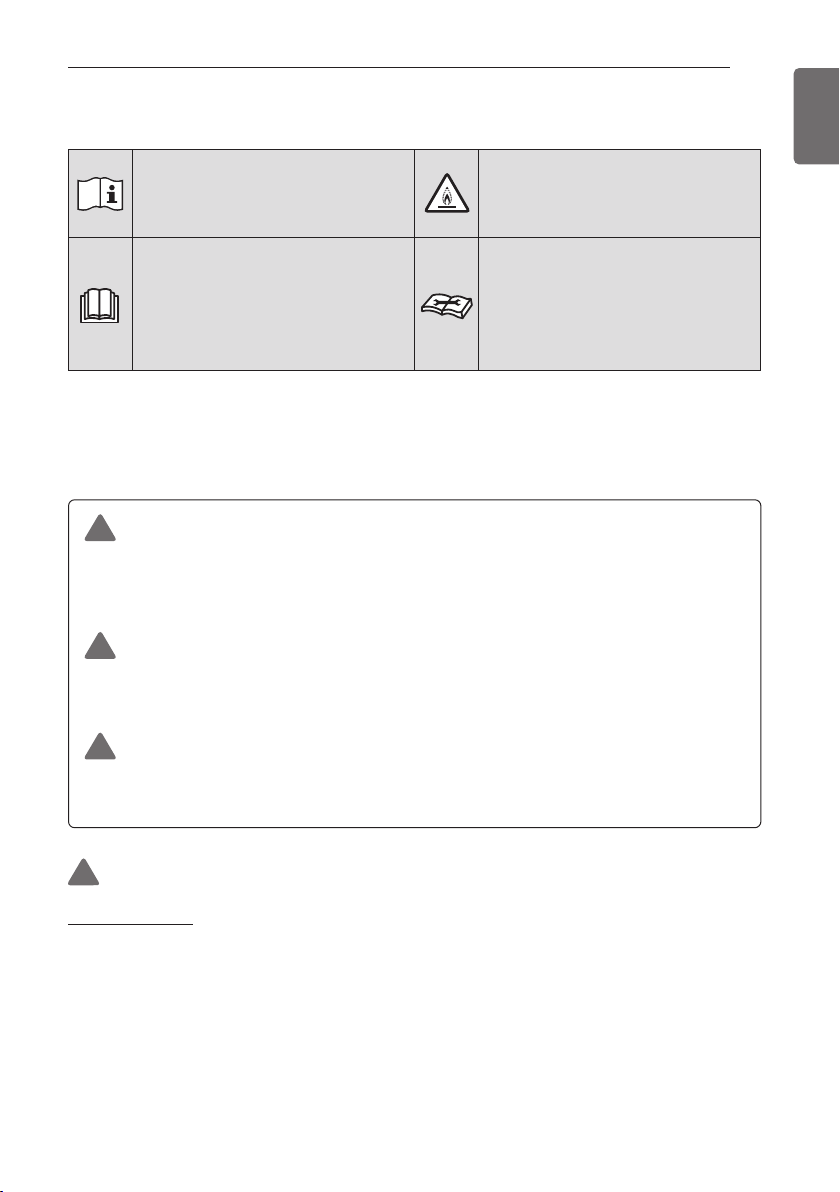
!
Read the precautions in this
manual carefully before
operating the unit.
This appliance is filled with
flammable refrigerant (R32)
This symbol indicates that
the Operation Manual should
be read carefully.
This symbol indicates that a
service personnel should be
handling this equipment with
reference to the Installation
Manual.
SAFETY INSTRUCTIONS
WARNING
This indicates that the failure to follow the instructions can
cause serious injury or death.
CAUTION
This indicates that the failure to follow the instructions can
cause the minor injury or damage to the product.
This symbol is displayed to indicate matters and
operations that can cause risk. Read the part with this
symbol carefully and follow the instructions in order to
avoid risk.
!
!
!
The following safety guidelines are intended to prevent
unforeseen risks or damage from unsafe or incorrect operation
of the appliance. The guidelines are separated into ‘WARNING’
and ‘CAUTION’ as described below.

10
SAFETY INSTRUCTIONS
ENGLISH
• Always ground the unit.
- There is risk of fire or electric shock.
• Install the panel and the cover of control box securely.
- There is risk of fire or electric shock.
• Always install a dedicated circuit and breaker.
- Improper wiring or installation may cause fire or electric
shock.
• Use the correctly rated breaker or fuse.
- There is risk of fire or electric.
• Do not modify or extend the power cable.
- There is risk of fire or electric shock.
• Do not install, remove, or reinstall the unit by yourself
(customer).
- There is risk of fire, electric shock, explosion, or injury
• For antifreeze, always contact the dealer or an authorized
service center.
- Almost the antifreeze is a toxic product.
• For installation, always contact the dealer or an authorized
Service Center.
- There is risk of fire, electric shock, explosion, or injury.
• Do not install the unit on a defective installation stand.
- It may cause injury, accident, or damage to the unit.
• Be sure the installation area does not deteriorate with age.
- If the base collapses, the unit could fall with it, causing
property damage, unit failure, and personal injury.
• Do not install the water pipe system as Open loop type.
- It may cause failure of unit.
• Use a vacuum pump or inert (nitrogen) gas when doing
leakage test or purging air. Do not compress air or oxygen and
do not use flammable gases.
- There is the risk of death, injury, fire or explosion.
• Make sure the connected condition of connector in product
after maintenance.
- Otherwise, it may cause product damage.

11
SAFETY INSTRUCTIONS
ENGLISH
• Do not touch leaked refrigerant directly.
- There is risk of frostbite.
• Copper in contact with refrigerants shall be oxygen-free or
deoxidized, for example Cu-DHP as specified in EN 12735-1
and EN 12735-2.
• Compliance with national gas regulations shall be observed.
(for R32)
• Refrigerant tubing shall be protected or enclosed to avoid
damage. (for R32)
• The installation of pipe-work shall be kept to a minimum. (for
R32)
• A brazed, welded, or mechanical connection shall be made
before opening the valves to permit refrigerant to flow
between the refrigerating system parts. A vacuum valve shall
be provided to evacuate the interconnecting pipe and/or any
uncharged refrigerating system part. (for R32)
• Any person who is involved with working on or breaking into a
refrigerant circuit should hold a current valid certificate from an
industry-accredited assessment authority, which authorises
their competence to handle refrigerants safely in accordance
with an industry recognised assessment specification. (for
R32)
• Do not use means to accelerate the defrosting process or to
clean, other than those recommended by the manufacturer.
(for R32)
• Do not pierce or burn. (for R32)
• Be aware that refrigerants may not contain an odour. (for R32)
• Dismantling the unit, treatment of the refrigerant oil and
eventual parts should be done in accordance with local and
national standards. (for R32)
• Flexible refrigerant connectors (such as connecting lines
between the indoor and outdoor unit) that may be displaced
during normal operations shall be protected against mechanical
damage. (for R32)

12
SAFETY INSTRUCTIONS
ENGLISH
• Pipe-work shall be protected from physical damage. (for R32)
• Mechanical connections (mechanical connectors or flared
joints) shall be accessible for maintenance purposes. (for R32)
Operation
• Take care to ensure that power cable could not be pulled out
or damaged during operation.
- There is risk of fire or electric shock.
• Do not place anything on the power cable.
- There is risk of fire or electric shock.
• Do not plug or unplug the power supply plug during operation.
- There is risk of fire or electric shock.
• Do not touch (operate) the unit with wet hands.
- There is risk of fire or electric shock.
• Do not place a heater or other appliances near the power
cable.
- There is risk of fire or electric shock.
• Do not allow water to run into electric parts.
- There is risk of fire, failure of the unit, or electric shock.
• Do not store or use flammable gas or combustibles near the
unit.
- There is risk of fire or failure of unit.
• Do not use the unit in a tightly closed space for a long time.
- It may cause damage to the unit.
• When flammable gas leaks, turn off the gas and open a
window for ventilation before turning the unit on.
- There is risk of explosion or fire.
• If strange sounds, or smell or smoke comes from unit, turn the
breaker off or disconnect the power supply cable.
- There is risk of electric shock or fire.

13
SAFETY INSTRUCTIONS
ENGLISH
• Stop operation and close the window in storm or hurricane. If
possible, remove the unit from the window before the
hurricane arrives.
- There is risk of property damage, failure of unit, or electric
shock.
• Do not open the front cover of the unit while operation. (Do
not touch the electrostatic filter, if the unit is so equipped.)
- There is risk of physical injury, electric shock, or unit failure.
• Do not touch any electric part with wet hands. you should be
power off before touching electric part.
- There is risk of electric shock or fire.
• Do not touch refrigerant pipe and water pipe or any internal
parts while the unit is operating or immediately after operation.
- There is risk of burns or frostbite, personal injury.
• If you touch the pipe or internal parts, you should be wear
protection or wait time to return to normal temperature.
- Otherwise , it may cause burns or frostbite, personal injury.
• Turn the main power on 6 hours ago before the product
starting operation.
- Otherwise, it may cause compressor damage.
• Do not touch electric parts for 10 minutes after main power
off.
- There is risk of physical injury, electric shock.
• The inside heater of product may operate during stop mode. It
is intended to protect the product.
• Be careful that some part of the control box are hot.
- There is risk of physical injury or burns.
• When the unit is soaked (flooded or submerged), contact an
Authorized Service Center.
- There is risk of fire or electric shock.
• Be cautious that water could not be poured to the unit directly.
- There is risk of fire, electric shock, or unit damage.

14
SAFETY INSTRUCTIONS
ENGLISH
• Ventilate the unit from time to time when operating it together
with a stove, etc.
- There is risk of fire or electric shock.
• Turn the main power off when cleaning or maintaining the unit.
- There is risk of electric shock.
• Take care to ensure that nobody could step on or fall onto the
unit.
- This could result in personal injury and unit damage.
• If the unit is not used for long time, we strongly recommend
not to switch off the power supply to the unit.
- There is risk of water freezing.
• The appliance shall be stored in a well-ventilated area where
the room size corresponds to the room area as specified for
operation. (for R32)
• The appliance shall be stored in a room without continuously
operating open flames (for example an operating gas
appliance) and ignition sources (for example an operating
electric heater). (for R32)
• The appliance shall be stored so as to prevent mechanical
damage from occurring. (for R32)
• Servicing shall only be performed as recommended by the
equipment manufacturer. Maintenance and repair requiring the
assistance of other skilled personnel shall be carried out under
the supervision of the person competent in the use of
flammable refrigerants. (for R32)
• When mechanical connectors are reused indoors, sealing parts
shall be renewed. When flared joints are reused indoors, the
flare part shall be re-fabricated. (for R32)
• Periodic(more than once/year) cleaning of the dust or salt
particles stuck on the heat exchangers by using water. (for
R32)
• Keep any required ventilation openings clear of obstruction.
(for R32)

15
SAFETY INSTRUCTIONS
ENGLISH
CAUTION
Installation
• Always check for gas (refrigerant) leakage after installation or
repair of unit.
- Low refrigerant levels may cause failure of unit.
• Keep level even when installing the unit.
- To avoid vibration or water leakage.
• Use two or more people to lift and transport the unit.
- Avoid personal injury.
• Do not install the unit in potentially explosive atmospheres.
Operation
• Do not use the unit for special purposes, such as preserving
foods, works of art, etc.
- There is risk of damage or loss of property.
• Use a soft cloth to clean. Do not use harsh detergents,
solvents, etc.
- There is risk of fire, electric shock, or damage to the plastic
parts of the unit.
• Do not step on or put anything on the unit.
- There is risk of personal injury and failure of unit.
• Use a firm stool or ladder when cleaning or maintaining the
unit.
- Be careful and avoid personal injury.
• Do not turn on the breaker or power under condition that front
panel cabinet, top cover, control box cover are removed or
opened.
- Otherwise it may cause fire, electric shock, explosion or
death.
• The appliance shall be disconnected from its power source
during service and when replacing parts.
• Means for disconnection must be incorporated in the fixed
wiring in accordance with the wiring rules.
!

16
SAFETY INSTRUCTIONS
ENGLISH
• The Installation kit supplied with the appliance are to be used
and that old Installation kit should not be reused.
• If the supply cord is damaged, it must be replaced by the
manufacturer, its service agent or similarly qualified persons in
order to avoid a hazard. Installation work must be performed in
accordance with the national wiring standards by authorized
personnel only.
• This equipment shall be provided with a supply conductor
complying with the national regulation.
• The instructions for service to be done by specialized
personnel, mandated by the manufacturer or the authorized
representative may be supplied in only one Community
language which the specialized personnel understand.
• This appliance is not intended for use by persons (including
children) with reduced physical, sensory or mental capabilities
or lack of experience and knowledge, unless they have been
given supervision or instruction concerning use of the
appliance by a person responsible for their safety. Children
should be supervised to ensure that they do not play with the
appliance.
17
INSTALLATION PART
ENGLISH
Thank you for choosing LG Electronics Air-to-Water Heat Pump
Before starting installation, please make it sure that all parts are found inside the product box.
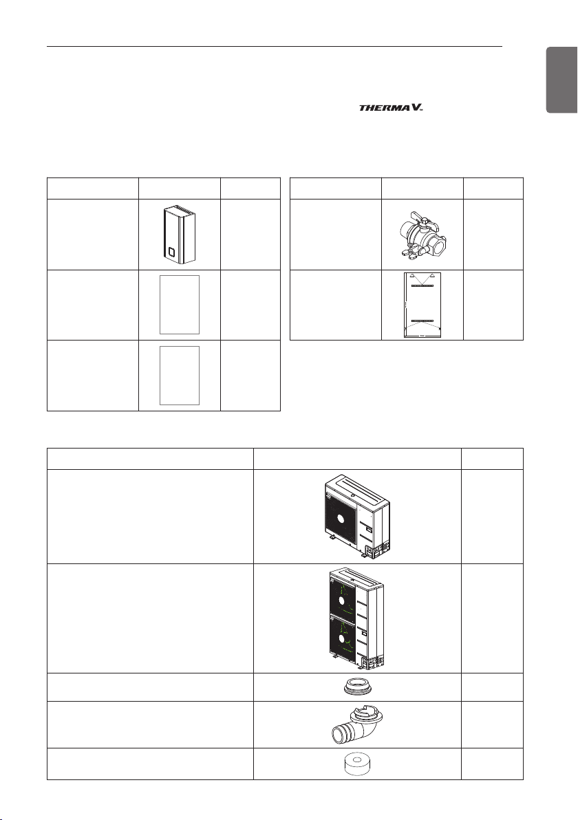
(For Split)
INDOOR UNIT BOX
INSTALLATION PART
OUTDOOR UNIT BOX
Item Image Quantity
Outdoor Unit
U36A Chassis
1
Outdoor Unit
U60A Chassis
1
Drain Cap 4
Drain Nipple 1
Damper 4
Item Image Quantity
Shut-off valve 2
Installation Sheet 1
Item Image Quantity
Indoor unit 1
Installation
Manual
1
Owner's /
Installation manual
1
18
INSTALLATION PART
ENGLISH
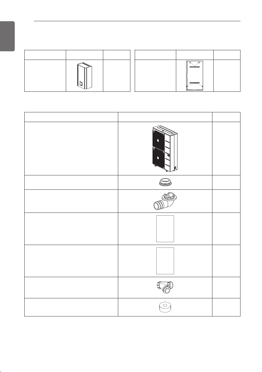
(For Hydrosplit)
INDOOR UNIT BOX
OUTDOOR UNIT BOX
Item Image Quantity
Outdoor Unit
U60A Chassis
1
Drain Cap 4
Drain Nipple 1
Installation Manual 1
Owner's / Installation manual 1
Strainer 1
Damper 4
Item Image Quantity
Indoor unit 1
Item Image Quantity
Installation Sheet 1
19
INSTALLATION PART
ENGLISH
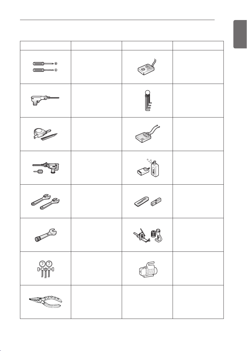
INSTALLATION TOOLS
Figure Name Figure Name
Screw driver Ohmmeter
Electric drill Hexagonal wrench
Measuring tape, Knife Ammeter
Hole core drill Leak detector
Spanner
Thermometer,
Horizontal meter
Torque wrench Flaring tool set
Manifold Gauge Vacuum Pump
Pliers - -
20
GENERAL INFORMATION
ENGLISH
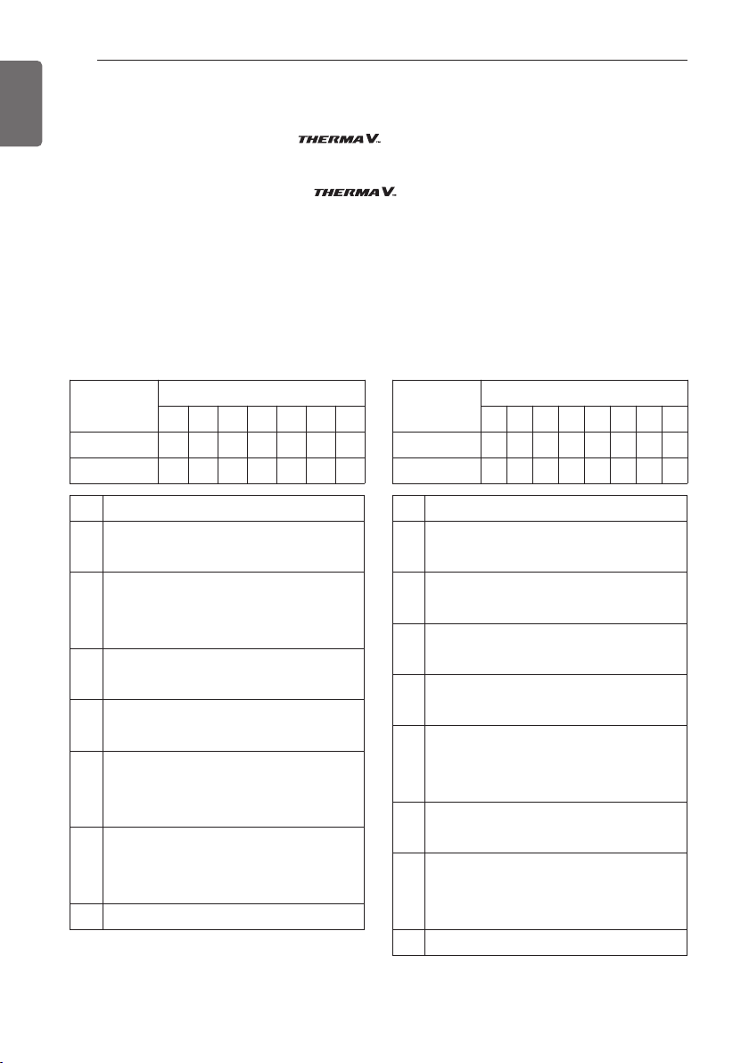
Model Information
Factory Model Name
Outdoor unit Indoor unit
Model
No.
1 2 3 4 5 6 7
Split ZH U W 09 6 A 0
Hydrosplit ZH B W 16 8 B 0
Signification
1
ZH : Air-to-Water-Heat Pump for R32
AH : Air-to-Water-Heat Pump for R410A
2
Classification
- U : Outdoor unit of Split
- B : Outdoor unit of Hydrosplit
3
Model Type
- W : Inverter Heat Pump
4
Heating Capacity
- e.g. 09 : 9 kW
5
Electrical ratings
- 6 : 1Ø, 220-240V, 50 Hz
- 8 : 3Ø, 380-415V, 50 Hz
6
Function
- A : General function of Split
- B : General function of Hydrosplit
7 Series number (Factory)
Model
No.
1 2 3 4 5 6 7 8
Split ZH N W 09 6 06 A 1
Hydrosplit ZH N W 16 · · B 0
Signification
1
ZH : Air-to-Water-Heat Pump for R32
AH : Air-to-Water-Heat Pump for R410A
2
Classification
- N : Indoor unit
3
Model Type
- W : Inverter Heat Pump
4
Heating Capacity
- e.g. 09 : 9 kW
5
Electrical ratings
- 6 : 1Ø, 220-240V, 50 Hz
- 8 : 3Ø, 380-415V, 50 Hz
6
Heater Capacity
- e.g. 06 : 6 kW Heater
7
Function
- A : General function of Split
- B : General function of Hydrosplit
8 Series number (Factory)
GENERAL INFORMATION
With advanced inverter technology, is suitable for applications like under floor
heating, under floor cooling, and hot water generation. By Interfacing to various accessories user
can customize the range of the application.
In this chapter, general information of is presented to identify the installation
procedure. Before beginning installation, read this chapter carefully and find helpful information
on installation.
Energy Labels and Product Fiches for all possible combinations can be found at
https://www.lg.com/global/support/cedoc/cedoc. Search for outdoor unit name in cedoc page.
21
GENERAL INFORMATION
ENGLISH
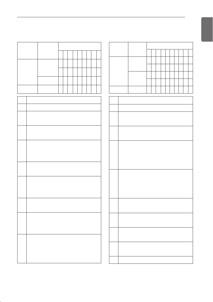
Buyer Model Name
Outdoor unit Indoor unit
Signification
1 Air-to-Water Heat Pump
2
Classification
- U : Outdoor unit
3
Heating Capacity
- e.g. 16 : 16 kW
4
Electrical ratings
- 1 : 1Ø, 220-240V, 50 Hz
- 3 : 3Ø, 380-415V, 50 Hz
5
Leaving water combination
- M : Medium Temperature
6
Refrigerant
- A : R410A
- R : R32
7
Function
- B : General function of Hydrosplit
8
Chassis
- U3 : U60A Chassis
- U4 : U36A Chassis
9
Series number (Buyer)
- HU*** U33 : Split R410A 3 Series
- HU***MA U33 : Split R410A 4 Series
- HU***MR U44 : Split R32 4 Series
- HU***MRB U30 : Hydrosplit 0 Series
Signification
1 Air-to-Water Heat Pump
2
Classification
- N : Indoor unit
3
Heating Capacity
- e.g. 09 : 9 kW
4
Electrical ratings
- 0 : For both 1Ø, 220-240V, 50 Hz and 3Ø,
380-415 V, 50 Hz
- 1 : 1Ø, 220-240V, 50 Hz
- 3 : 3Ø, 380-415V, 50 Hz
5
Heater capacity (kW)
- 0 : Optional Accessory
- 6 : 6 kW Heater
- 9 : 9 kW Heater
* For R32 5 Series : 6 kW Heater
6
Leaving water combination
- M : Medium Temperature
7
Refrigerant
- R : R32
8
Function
- B : General function of Hydrosplit
9
Chassis
- NK : K1 Chassis
10 Series number (Buyer)
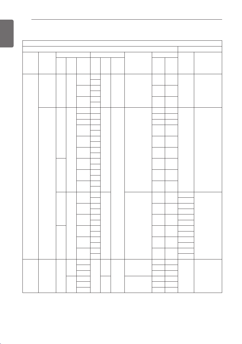
Type Refrigerant
No.
1 2 3 4 5 6 7 8 9
Split
R410A
H U 16 1 · · · U3 3
H U 16 1 M A · U3 3
R32
H U 05 1 M R · U4 4
Hydrosplit R32
H U 16 3 M R B U3 0
Type Refrigerant
No.
1 2 3 4 5 6 7 8 9 10
Split
R410A
H N 16 1 6 · · · NK 3
H N 16 1 6 M · · NK 5
R32
H N 09 1 6 M · · NK 4
H N 09 1 · M R · NK 5
Hydrosplit R32
H N 16 0 0 M · B NK 0
Check the model information based on the buyer model series number.
(e.g., geometry, cycle, etc.)
22
GENERAL INFORMATION
ENGLISH
Related Information
*1 : tested under EN14511
(water temperature 30 °C ’ 35 °C at outdoor ambient temperature 7 °C / 6 °C)
*2 : tested under EN14511
(water temperature 23 °C ’ 18 °C at outdoor ambient temperature 35 °C / 24 °C)
h All appliances were tested at atmospheric pressure.
Unit
Heat Pump Backup Heater
Type Refrigerant
Outdoor Unit Indoor Unit
Power Supply
Capacity
Capacity
[kW]
Power Supply
Series Phase
Capacity
[kW]
Series Phase
Capacity
[kW]
Heating
[kW]
*1
Cooling
[kW]
*2
Split
R32 0 1Ø
5
4
1Ø 9 220-240 V~50 Hz
5.5 5.5
6 (3+3) 220-240 V~50 Hz
5
7
4
7.0 7.0
5
9
4
9.0 9.0
5
R410A
3
1Ø
5 3
1Ø
16
220-240 V~50 Hz
5.0 5.0
6 (3+3) 220-240 V~50 Hz
7 3 7.0 7.0
9 3 9.0 9.0
12
3
12.0 10.4
5
14
3
14.0 12.0
5
16
3
16.0 13.0
5
4
12
3
12.0 10.4
5
14
3
14.0 12.0
5
16
3
16.0 13.0
5
3
3Ø
12
3
3Ø 380-415 V~50 Hz
12.0 10.4
9 (3+3+3)
380-415 V~50 Hz
5 6 (2+2+2)
14
3
14.0 12.0
9 (3+3+3)
5 6 (2+2+2)
16
3
16.0 13.0
9 (3+3+3)
5 6 (2+2+2)
4
12
3
12.0 10.4
9 (3+3+3)
5 6 (2+2+2)
14
3
14.0 12.0
9 (3+3+3)
5 6 (2+2+2)
16
3
16.0 13.0
9 (3+3+3)
5 6 (2+2+2)
Hydrosplit R32 0
1Ø
12
0
1Ø
16
220-240 V~50 Hz
12.0 12.0
- -
14 14.0 14.0
16 16.0 16.0
3Ø
12
3Ø 380-415 V~50 Hz
12.0 12.0
14 14.0 14.0
16 16.0 16.0
23
GENERAL INFORMATION
ENGLISH
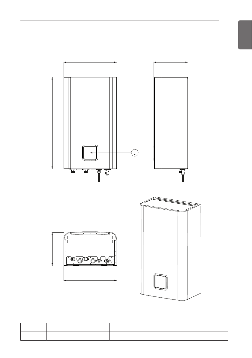
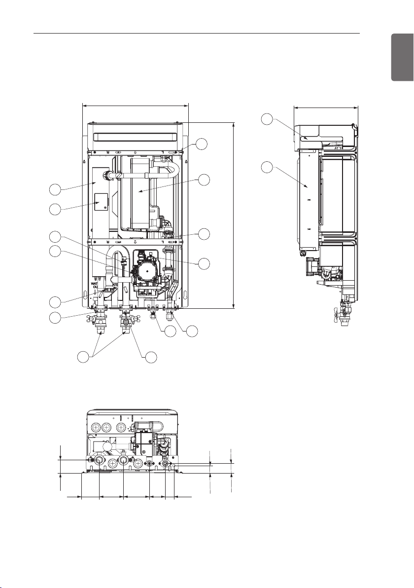
Parts and Dimensions
Indoor unit : External
* The feature may be vary according to the type of model.
Description
No Name Remark
1 Control Panel Built-in Remote Controller
(unit : mm)
850315
490
315
490
24
GENERAL INFORMATION
ENGLISH
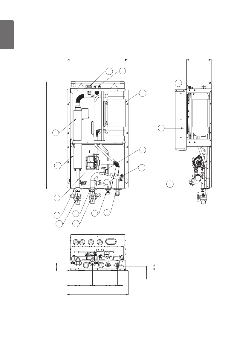
(unit : mm)
Indoor unit : Internal
- For Split R410A Indoor unit 3 Series
484 289.6
9
13
12
10
847.8
8
14
5
1
16
63.4
16
7
6
15
11
4
2
3
12311684.5 76 41
484
36.9
46.4
25
GENERAL INFORMATION
ENGLISH
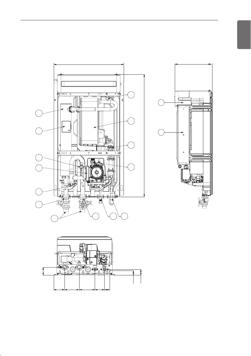
(unit : mm)
Indoor unit : Internal
- For Split R410A Indoor unit 5 Series
14
11
15
484
307
13
12
10
8
7
847.8
9
5
6
1
16
2 3 4
63.4
115.584.5
123.5 76 41
36.9
46.4
26
GENERAL INFORMATION
ENGLISH
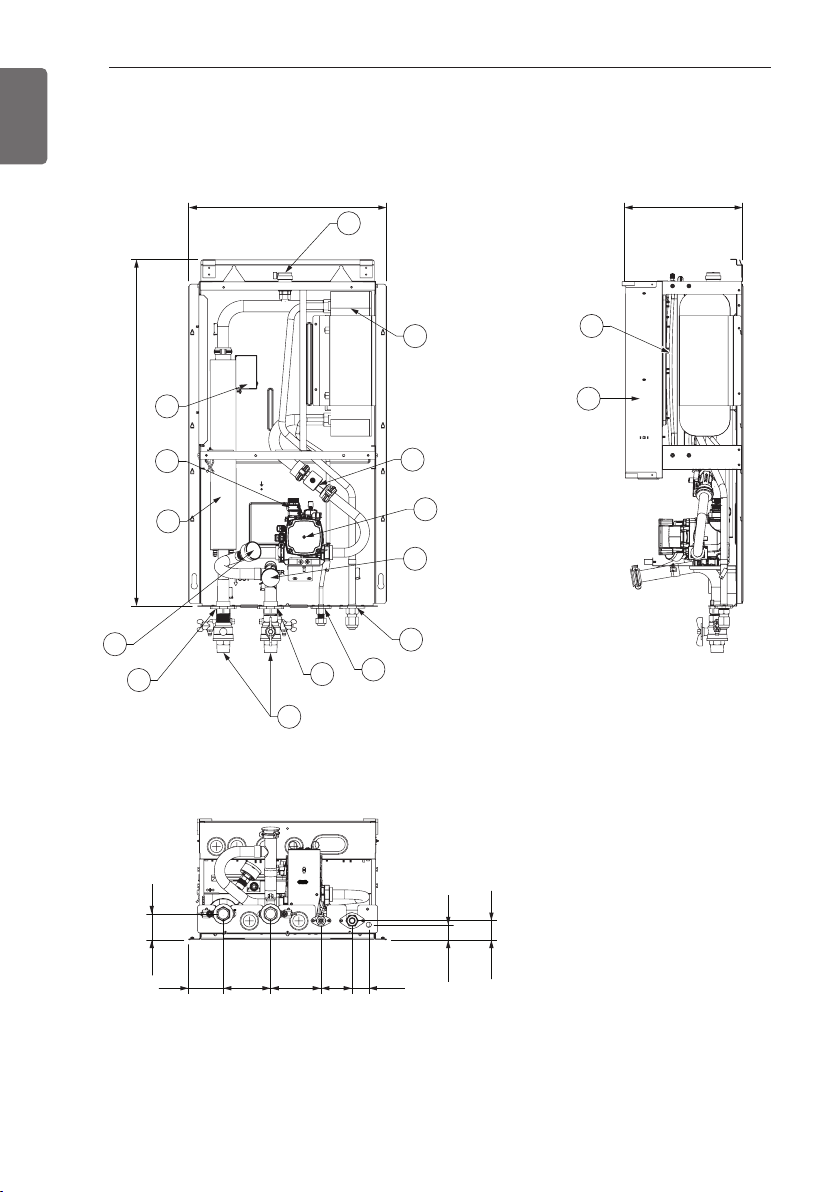
(unit : mm)
Indoor unit : Internal
- For Split R32 Indoor unit 4 Series
484 289.5
13
11
848.8
1
14
10
8
6
9
12
7
5
15
4
3
2
16
63.4
84.9 115.6 123.3 76 40.7
36.9
46.9
27
GENERAL INFORMATION
ENGLISH
(unit : mm)
Indoor unit : Internal
- For Split R32 Indoor unit 5 Series
14
11
15
484
307
12
13
7
10
8
847.8
9
5
6
1
43
16
2
63.4
84.5 115.5 123.5 76 41
36.9
46.4
28
GENERAL INFORMATION
ENGLISH
(unit : mm)
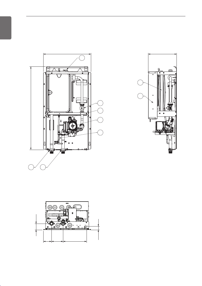
Indoor unit : Internal
- For Hydrosplit
847.8
484 289
9
8
5
6
4
3
7
1
2
63.4
84.5 116 240
36.9
29
GENERAL INFORMATION
ENGLISH
No Name Remark
1 Leaving Water Pipe Male PT 1 inch
2 Entering Water Pipe Male PT 1 inch
3 Refrigerant Pipe Ø 9.52 mm
4 Refrigerant Pipe Ø 15.88 mm
5 Water Pump Max Head 9.5 / 7 / 6 m
6 Safety Valve Open at water pressure 3 bar
7 Control Box PCB and terminal blocks
8 Thermal switch
Cut-off power input to backup heater at 90 °C
(manual return at 55 °C)
9
Flow Switch Minimum operation range at 15 LPM.
Flow Sensor Range : 5 ~ 80 L/min
10 Plate Heat Exchanger Heat exchange between refrigerant and water
11
Pressure Gauge Indicates circulating water pressure
Pressure Sensor Detects circulating water pressure
12 Expansion Tank Absorbing Volume change of heated water
13 Air Vent Air purging when Charging water
14 Backup heater
Cut-off power input to backup heater at 184 °C
(Not Recoverable)
15 Strainer Filtering and stacking particles inside circulating water
16 Shut-off valve To drain or to block water when pipe connecting
- For Split
No Name Remark
1 Leaving Water Pipe Male PT 1 inch
2 Entering Water Pipe Male PT 1 inch
3 Water Pump Circulating the water
4 Safety Valve Open at water pressure 3 bar
5 Control Box PCB and terminal blocks
6 Flow Sensor Range : 5 ~ 80 L/min
7 Pressure Sensor Detects circulating water pressure
8 Expansion Tank Absorbing Volume change of heated water
9 Air Vent Air Pumping when Charging water
- For Hydrosplit
30
GENERAL INFORMATION
ENGLISH
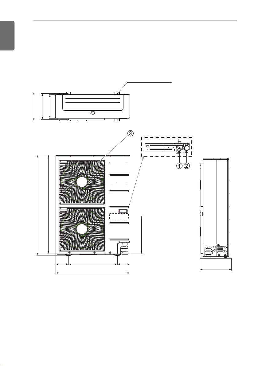
(unit : mm)
Outdoor unit : External
- For Split
Product Heating Capacity : 12 kW, 14 kW, 16 kW
Chassis : U60A
390
360
330
4-holes for anchor bolts
Supporter
1 380
1 356
165 165
620
950
490
390
 Loading...