

Lg Hmh12as-0 Installation Guide
DELUXE HIGH WALL MINI SPLIT
INSTALLATION INSTRUCTIONS
IMPORTANT!
Please read this instruction sheet completely before installing the product.
This air conditioning system meets strict safety and operating standards. As the installer or service person, it is an important part of
your job to install or service the system so it operates safely and efficiently.
CAUTION: Improper installation, adjustment, alteration, service or maintenance can void the warranty.
The weight of the condensing unit requires caution and proper handling procedures when lifting or moving to avoid
personal injury. Use care to avoid contact with sharp or pointed edges.
Safety Precautions
• Always wear safety eye wear and work gloves when installing equipment.
• Never assume electrical power is disconnected. Check with meter and equipment.
• Keep hands out of fan areas when power is connected to equipment.
• R-22 causes frostbite burns.
• R-22 is toxic when burned.
NOTE TO INSTALLING DEALER:
The Owners Instructions and Warranty are to be given to the owner or prominently displayed
near the indoor Furnace/Air Handler Unit.
P/No:3828A30044P
When wiring:
Electrical shock can cause severe personal injury or death. Only a qualified, experienced electrician
should attempt to wire this system.
• Do not supply power to the unit until all wiring and tubing are completed or reconnected and checked.
• Highly dangerous electrical voltages are used in this system. Carefully refer to the wiring diagram and these instructions when
wiring. Improper connections and inadequate grounding can cause accidental injury or death.
• Ground the unit following local electrical codes.
• Connect all wiring tightly. Loose wiring may cause overheating at connection points and a possible fire hazard.
When transporting:
Be careful when picking up and moving the indoor and outdoor units. Get a partner to help, and bend your knees when
lifting to reduce strain on your back. Sharp edges or thin aluminum fins on the air conditioner can cut your finger.
When installing...
... in a wall: Make sure the wall is strong enough to hold the unit's weight.
It may be necessary to construct a strong wood or metal frame to provide added support.
... in a room: Properly insulate any tubing run inside a room to prevent "sweating" that can cause dripping and water
damage to wall and floors.
... in moist or uneven locatinons: Use a raised concrete pad or concrete blocks provide a solid, level foundation for the
outdoor unit. This prevents water damage and abnormal vibration.
... in an area with high winds:
Securely anchor the outdoor unit down with bolts and a metal frame. Provide a suitable air baffle.
... in a snowy area(for Heat Pump Model): Install the outdoor unit on a raised platform that is higher than drifting snow.
Provide snow vents.
When connecting refrigerant tubing
• Keep all tubing runs as short as possible.
• Use the flare method for connecting tubing.
• Check carefully for leaks before starting the test run.
When servicing
•
Turn the power OFF at the main power box(mains) before opening the unit to check or repair electrical parts and wiring.
• Keep your fingers and clothing away from any moving parts.
• Clean up the site after you finish, remembering to check that no metal scraps or bits of wiring have been left inside the unit
being serviced.
• Installation or repairs made by unqualified persons can result in hazards to you and others.
Installation MUST conform with local building codes or, in the absence of local codes, with the National Electrical Code NFPA
70/ANSI C1-1993 or current edition and Canadian Electrical Code Part1 CSA C.22.1.
• The information contained in the manual is intended for use by a qualified service technician familiar with safety procedures and
equipped with the proper tools and test instruments.
• Failure to carefully read and follow all instructions in this manual can result in equipment malfunction, property damage, personal
injury and/or death.
WARNING
Special warnings
2
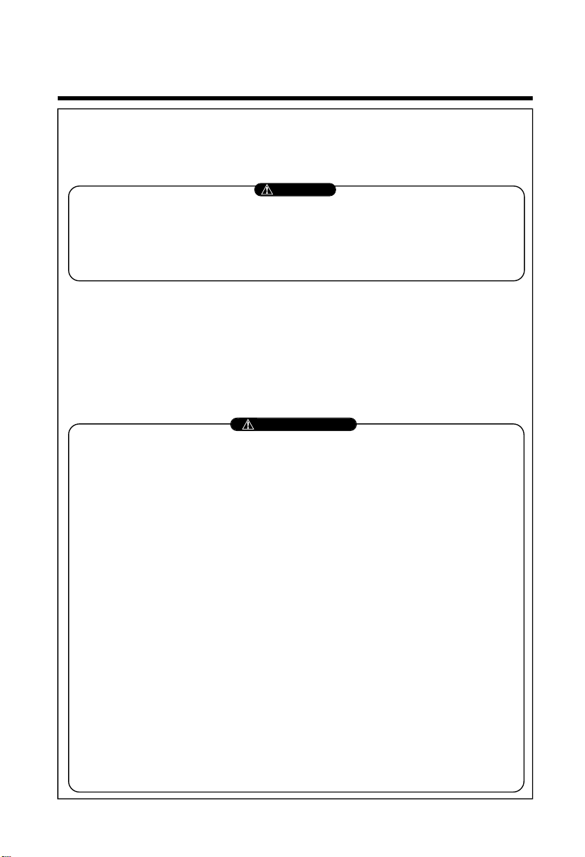
1. Type "A" screw
2. Installation Plate
3. Type "B" screw
4. Holder Remote Control
OUT-LINE OF INSTALLATION
Installation
Requirements
Required Parts Required Tools
The following should be
always observed for safety.3
Installation of indoor, outdoor
unit
............................................
4
❏ Installation plate
❏Four type "A" screws
❏Connecting cable
❏Level gauge
❏Screw driver
❏Electric drill
❏Hole core drill ø70mm(2.79")
Flaring work and connection
of piping
...................................
6
Connection of piping(Indoor)..7
For right rear piping
For left rear piping
Connection of
piping(Outdoor)
..................
10
Connecting the cable
between indoor unit and
outdoor unit
..........................
11
❏Pipes:
Gas side
...............
1/2"(9K,12K)
5/8"(18K,24K)
Liquid side
....
1/4"(9K,12K,18K)
3/8"(24K)
(Refer to page 4)
❏Insulation materials
❏Additional drain pipe
Outer Diameter
......
15.5mm(5/8")
❏Flaring tool set
❏Specified torque wrenches
Liquid side -1.8kg.m(13ft.lbs):9K,12K,18K
4.0kg.m(28.9ft.lbs):24K
Gas side - 5.5kg.m(39.8ft.lbs):9K, 12K
6.6kg.m(47.7ft.lbs):18K, 24
K
❏Spanner..................Half union
Checking the drainage and
Forming the piping
................
14
Air Purging
.............................
15
❏A glass of water
❏Screw driver
❏Hexagonal
Wrench(4mm:5/32")
Test running
..........................
17 ❏Two type "B" screws ❏Owner's manual
❏Thermometer
❏Holder Remote Control
Installation Parts Provided
3
CAUTION
CAUTION
WARNING
WARNING
CAUTION
CAUTION
WARNING
WARNING
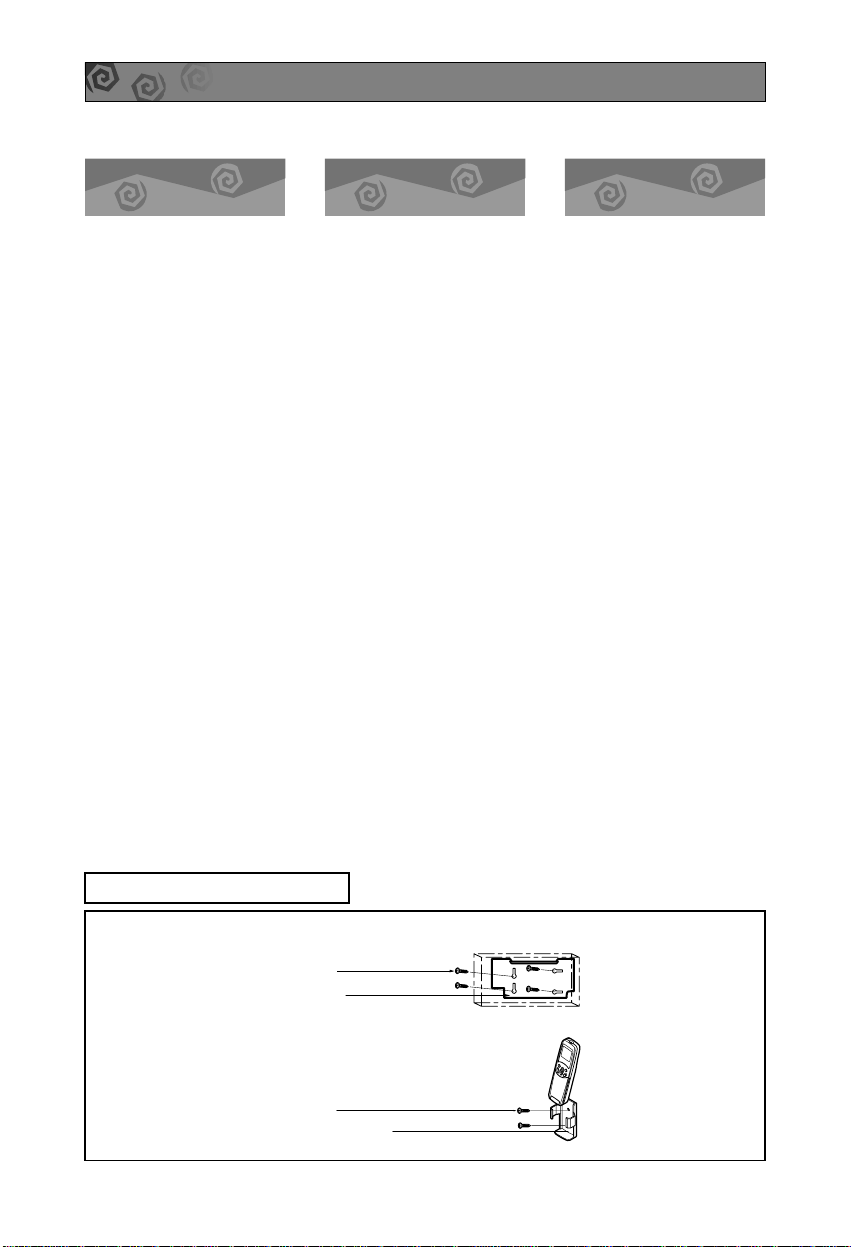
THE FOLLOWING SHOULD BE ALWAYS OBSERVED FOR SAFETY
• Be sure to read "THE FOLLOWING SHOULD ALWAYS BE OBSERVED FOR SAFETY" before installing
the air conditioner.
• Be sure to observe the cautions specified here as they include important items related to safety.
• The indications and meanings are as follows.
• After reading this manual, be sure to keep it together with the instruction manual in a handy place on the
customer's site.
Could lead to death, serious injury, etc.
Could lead to serious injury in particular environments when operated incorrectly.
Do not install it yourself (customer).
• Incomplete installation could cause injury due to
fire, electric shock, the unit falling or a leakage
of water. Consult the dealer from whom you
purchased the unit or special installer.
Perform the drainage/piping work securely
according to the installation manual.
• If there is a defect in the drainage/piping work,
water could drop from the unit and household
goods could be wet and damaged.
Do not install the unit in a place where an
inflammable gas leaks.
• If gas leaks and accumulates in the area
surrounding the unit, it could cause an
explosion.
Perform the installation securely referring to
the installation manual.
• Incomplete installation could cause a personal
injury due to fire, electric shock, the unit falling or
a leakage of water.
Install the unit securely in a place which can
bear the weight of the unit.
• When installed in an insufficient strong place,
the unit could fall causing injured.
Use the specified wires to connect the indoor and outdoor
units securely and attach the wires firmly to the terminal
board connecting sections so the stress of the wires is not
applied to the sections.
• Incomplete connecting and fixing could cause
fire.
Check that the refrigerant gas due not leak
after installation is completed.
Perform electrical work according to the
installation manual and be sure to use an
exclusive circuit.
• If the capacity of the power circuit is insufficient
or there is incomplete electrical work, it could
result in a fire or an electric shock.
Attach the electrical part cover to the indoor
unit and the service panel to the outdoor unit
securely.
• If the electrical part cover if the indoor unit and/or
the service panel if the outdoor unit are not
attached securely, it could result in a fire or
electric shock due to dust, water, etc.
Be sure to use the part provided or specified
parts for the installation work.
• The use of defective parts could cause an injury or leakage
of water due to a fire, electric shock, the unit falling, etc.
4
A
A
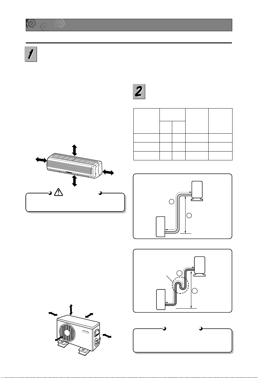
Oil trap
Outdoor unit
Indoor unit
B
Outdoor unit
Indoor unit
B
CAUTION
CAUTION
CAUTION
CAUTION
More than 5cm(2")
More than
5cm(2")
More than 2.3m(7.5ft)
More than
5cm(2")
More than
10cm(4")
More than 10cm(4")
More
than 60cm(24")
More than 60cm(24")
More than
70cm(28")
INSTALLATION OF INDOOR, OUTDOOR UNIT
Read completely, then follow step by step.
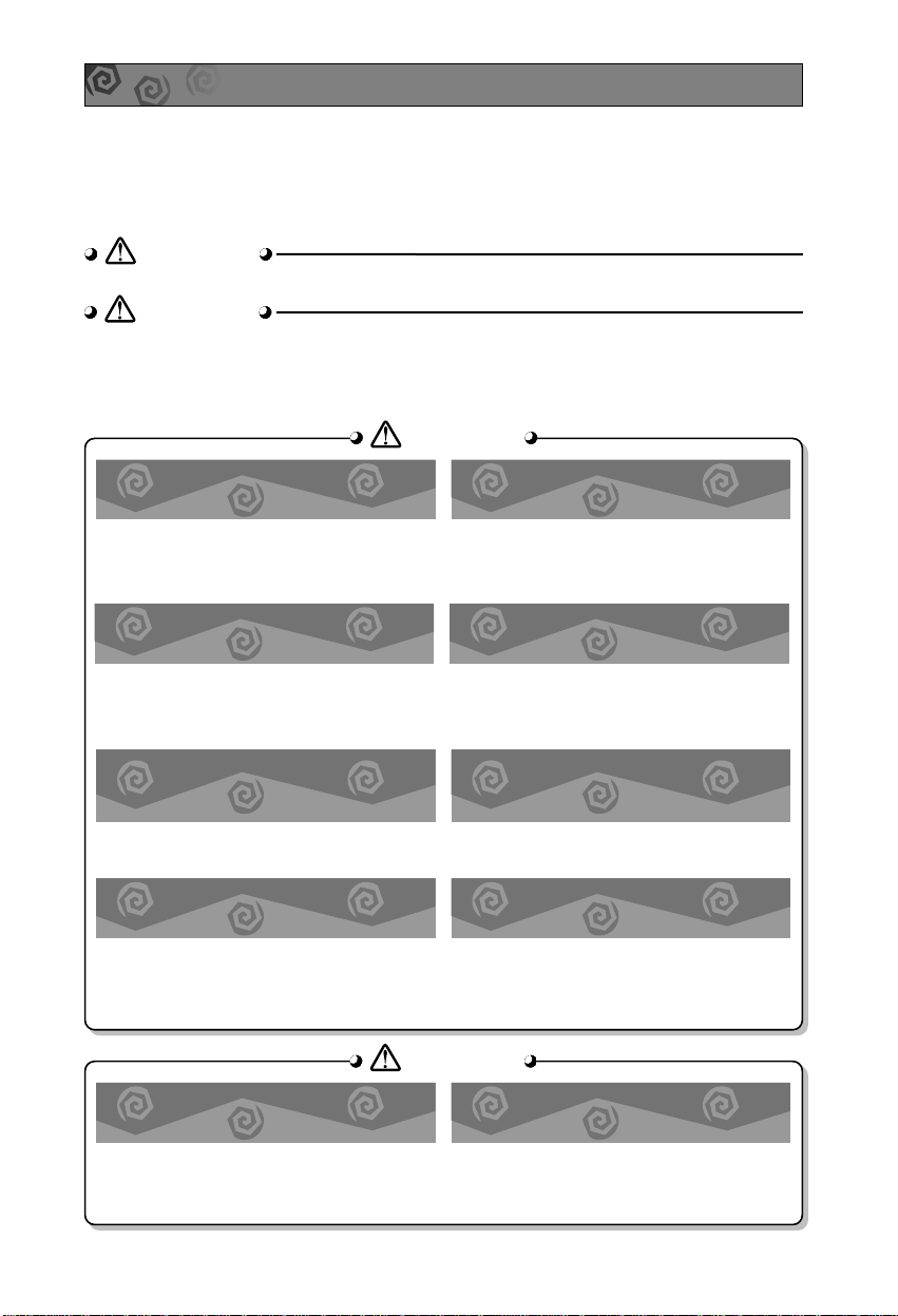
Select the best location
1. Indoor unit
■ Do not have any heat or steam near the
unit.
■ Select a place where there are no
obstacles in front of the unit.
■ Make sure that condensation drainage can
be conveniently routed away.
■ Do not install near a doorway.
■ Ensure that the space around the left and
right of the unit is more than 5cm(2"). The
unit should be installed as high on the wall
as possible, allowing a minimum of
5cm(2") from ceiling.
■ Use a stud finder to locate studs to prevent
unnecessary damage to the wall.
■ Rooftop Installations:
If the outdoor unit is installed on a roof
structure, be sure to level the unit. Ensure the
roof structure and anchoring method are
adequate for the unit location. Consult local
codes regarding rooftop mounting.
Piping length and elevation
2. Outdoor unit
■ If an awning is built over the unit to prevent
direct sunlight or rain exposure, make sure
that heat radiation from the condenser is not
restricted.
■ Ensure that the space around the back and
sides is more than 10cm. The front of the unit
should have more than 70cm of space.
■ Do not place animals and plants in the path
of the warm air.
■ Take the air conditioner weight into account
and select a place where noise and vibration
are minimum.
■ Select a place so that the warm air and noise
from the air conditioner do not disturb
neighbors.
Install the indoor unit on the wall where the height
from the floors more than 2.3 meters(7.5ft).
In case more than 5m(16.4ft)
• Capacity is based on standard length and maximum
allowance length is on the basis of reliability.
• Oil trap should be installed every 5~7 meters(16.4~23ft).
Pipe Size
MODEL
(Cooling Capa.)
GAS LIQUID
Max.
length
A
Max.
Elevation
B
9K, 12K 1/2" 1/4" 15m(50ft) 8m(26ft)
18K 5/8" 1/4" 15m(50ft) 8m(26ft)
24K 5/8" 3/8" 15m(50ft) 8m(26ft)
5
5-7mm
(0.2~0.3")
Indoor
WALL
Outdoor
Hole center
Right rear piping
Left rear piping
ø70mm
(2.76")
ø70mm
(2.76")
50mm
(1.97")
20mm
(0.79")
20mm
(0.79")
80mm(3.15")
A,B
A,B,C
C
D
D
A,B,D
C
A
B,D
C
ø70mm(2.76")
Left rear piping Right rear piping
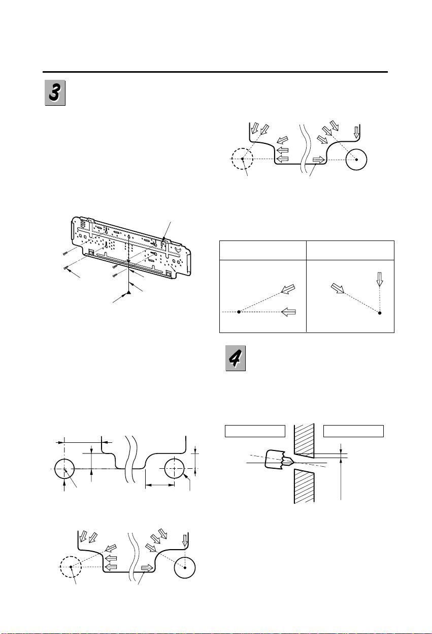
Hole Center Installation plate
A,B
A,B,C
C
D
D
A,B,D
C
A
B,D
C
ø70mm(2.76")
Left rear piping Right rear piping
Hole Center Installation plate
How to fix installation
plate
The wall you select should be strong
and solid enough to prevent vibration
1. Mount the installation plate on the
wall with four type A screws. If
mounting the unit on a concrete wall,
use anchor bolts.
■ Mount the installation plate
horizontally by aligning the centerline
using a level.
2. Measure the wall and mark the
centerline. It is also important to use
caution concerning the location of
the installation plate-routing of the
wiring to power outlets is through the
walls typically. Drilling the hole
through the wall for piping
connections must be done safely.
Drill a hole in the wall
■ Drill the piping hole with a ø70mm
(0.76") hole core drill. Drill the piping
hole at either the right or the left with
the hole slightly slanted to the outdoor
side.
Installation Plate
Marking-off line
Thread
Weight
Type "A" screw
12K Btu
18K, 24K Btu
9K Btu
■ For right rear piping and left rear piping, draw a
line in the direction of the arrow marked "A".
The meeting point of the two lines is the center
of the hole.
• The position of the center of the hole.
A
A
A
A
Left holecore position Right holecore position
6
Flare nut
Copper tube
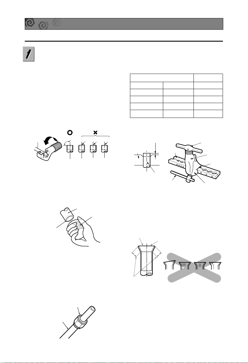
FLARING WORK AND CONNECTION OF PIPING
Flaring work
Main cause for gas leakage is due to
defect in flaring work. Carry out correct
flaring work in the following procedure.
1. Cut the pipes and the cable.
■ Use the piping kit accessory or the
pipes purchased locally.
■ Measure the distance between the
indoor and the outdoor unit.
■ Cut the pipes a little longer than
measured distance.
■ Cut the cable 1.5m(4.9ft) longer than
the pipe length.
2. Burrs removal
■ Completely remove all burrs from the
cut cross section of pipe/tube.
■ Put the end of the copper tube/pipe in
a downward direction as you remove
burrs in order to avoid dropping burrs
into the tubing.
3. Putting nut on
■ Remove flare nuts attached to indoor
and outdoor unit, then put them on
pipe/tube having completed burr
removal.
(not possible to put them on after
flaring work)
4. Flaring work
■ Carry out flaring work using flaring tool as
shown below.
Firmly hold copper pipe in a die in the
dimension shown in the table above.
5. Check
■ Compare the flared work with figure below.
■ If flare is noted to be defective, cut off the
flared section and do flaring work again.
Copper
pipe
90°
Slanted Uneven Rough
Pipe
Reamer
Point down
Outside diameter A
mm inch mm
ø6.35 1/4 0~0.5
ø9.52 3/8 0~0.5
ø12.7 1/2 0~0.5
ø15.88 5/8 0~1.0
Bar
Copper pipe
Clamp handle
Red arrow mark
Cone
Yoke
Handle
Bar
"A"
Inclined
Inside is shiny without scratches
Smooth all round
Even length
all round
Surface
damaged
Cracked Uneven
thickness
= Improper flaring =
 Loading...