

LG H32H49S Service Manual

Installation Guide & Warranty
Model Numbers | H27H49S • H32H49S Direct-View Presentation
TM
TVs
© Copyright 2006, LGElectronics U.S.A., Inc.
Zenith and the lightning Z logo are registered
trademarks of Zenith Electronics Corporation
WARNING
RISK OF ELECTRIC SHOCK
DO NOT OPEN
For Customer Support/Service, please call:
1-888-865-3026
www.lgcommercial.com • www.zenith.com
RECORD MODEL/SERIAL NUMBERS
The model-serial numbers of this Presentation
are located on the back of the cabinet. For future reference, we suggest that you record those numbers:
Model No. Serial No.
____________ _____________________________
TM
TV
WARNING: TO REDUCE THE RISK OF ELECTRIC SHOCK DO NOT REMOVE COVER (OR BACK). NO USER
SERVICEABLE PARTS INSIDE. REFER TO QUALIFIED SERVICE PERSONNEL.
The lightning flash with arrowhead symbol, within an equilateral triangle, is intended to alert
the user to the presence of uninsulated “dangerous voltage” within the product’s enclosure
that may be of sufficient magnitude to constitute a risk of electric shock to persons.
The exclamation point within an equilateral triangle is intended to alert the user to the presence of important operating and maintenance (servicing) instructions in the literature accompanying the appliance.
WARNING:
TO PREVENT FIRE OR SHOCK HAZARDS, DO NOT EXPOSE THIS PRODUCT TO RAIN OR MOISTURE.
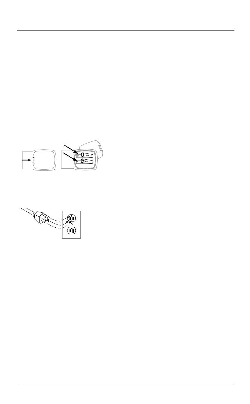
POWER CORD POLARIZATION:
This product is equipped with a 3-wire grounding-type alternating current line plug. This plug will fit into the
power outlet only one way. This is a safety feature. If you are unable to insert the plug fully into the outlet,
contact your electrician to replace your obsolete outlet. Do not defeat the safety purpose of the three-wire
ground type plug.
NOTE TO CABLE/TV INSTALLER:
This reminder is provided to call the cable TV system installer’s attention to Article 820-40 of the National
Electric Code (U.S.A.). The code provides guidelines for proper grounding and, in particular, specifies that the
cable ground shall be connected to the grounding system of the building, as close to the point of the cable
entry as practical.
REGULATORY INFORMATION:
This equipment has been tested and found to comply with the limits for a Class B digital device, pursuant to
Part 15 of the FCC Rules. These limits are designed to provide reasonable protection against harmful interference when the equipment is operated in a residential installation. This equipment generates, uses and can
radiate radio frequency energy and, if not installed and used in accordance with the instruction manual, may
cause harmful interference to radio communications. However, there is no guarantee that interference will not
occur in a particular installation. If this equipment does cause harmful interference to radio or television
reception, which can be determined by turning the equipment off and on, the user is encouraged to try to
correct the interference by one or more of the following measures:
• Reorient or relocate the receiving antenna.
• Increase the separation between the equipment and receiver.
• Connect the equipment into an outlet on a circuit different from that to which the receiver is connected.
• Consult the dealer or an experienced radio/TV technician for help.
CAUTION:
Do not attempt to modify this product in any way without written authorization from LG Electronics
U.S.A., Inc. Unauthorized modification could void the user’s authority to operate this product.
COMPLIANCE:
The responsible party for this product’s compliance is: LG Electronics U.S.A., Inc.
1000 Sylvan Avenue, Englewood Cliffs, NJ 07632, USA • Phone: 1-201-816-2000.
Marketed and Distributed in the United States by LG Electronics U.S.A., Inc.
2000 Millbrook Drive, Lincolnshire, IL 60069
TM
Presentation
is a registered trademark of Zenith Electronics Corporation
© Copyright 2006, LG Electronics U.S.A., Inc.
Page 2

IMPORTANT SAFETY INSTRUCTIONS
Important safeguards for you and your new product
Your product has been manufactured and tested with your safety in mind. However, improper use can result
in potential electrical shock or fire hazards. To avoid defeating the safeguards that have been built into
your new product, please read and observe the following safety points when installing and using your new
product, and save them for future reference.
Observing the simple precautions discussed in this operating guide can help you get many years of enjoyment and safe operation that are built into your new product.
1. Read Instructions
All the safety and operating instructions should be
read before the product is operated.
2. Follow Instructions
All operating and use instructions should be followed.
3. Retain Instructions
The safety and operating instructions should be
retained for future reference.
4. Heed Warnings
All warnings on the product and in the operating
instructions should be adhered to.
5. Cleaning
Unplug this product from the wall outlet before
cleaning. Do not use liquid cleaners or aerosol
cleaners. Use a damp cloth for cleaning.
6. Water and Moisture
Do not use this product near water for example,
near a bath tub, wash bowl, kitchen sink, or laundry tub, in a wet basement, or near a swimming
pool.
7. Accessories, Carts, and Stands
PORTABLE CART WARNING
Do not place this product on a slippery or tilted
surface, or on an unstable cart, stand, tripod,
bracket, or table. The product may fall, causing
serious injury to a child or adult, and serious damage to the product. Use only with a cart, stand, tripod, bracket, or table recommended by the manufacturer, or sold with the product. Any mounting of
the product should follow the manufacturer’s
instructions, and should use a mounting accessory
recommended by the manufacturer.
8. Transporting Product
A product and cart combination should be moved
with care. Quick stops, excessive force, and uneven
surfaces may cause the product and cart combination to overturn.
9. Attachments
Do not use attachments not recommended by the
product manufacturer as they may cause hazards.
10. Ventilation
Slots and openings in the cabinet are provided for
ventilation and to ensure reliable operation of the
product and to protect it from overheating, and
these openings must not be blocked or covered. The
openings should never be blocked by placing the
product on a bed, sofa, rug, or other similar surface. This product should not be placed in a built-in
installation such as a bookcase or rack unless proper ventilation is provided or the manufacturer’s
instructions have been adhered to.
11. Power Sources
This product should be operated only from the type
of power source indicated on the marking label. If
you are not sure of the type of power supply to
your home, consult your product dealer or local
power company. For products intended to operate
from battery power, or other sources, refer to the
operating instructions.
12. Power Cord Polarization
This product is equipped with a 3-wire grounding
type alternating-current power plug. This plug will
fit into the power outlet only one way. This is a
safety feature. If you are unable to insert the plug
fully into the outlet, contact your electrician to
replace your obsolete outlet. Do not defeat the
safety purpose of the three-wire ground-type plug.
13. Power Cord Protection
Power-supply cords should be routed so that they
are not likely to be walked on or pinched by items
placed upon or against them, paying particular
attention to cords at plugs, convenience receptacles, and the point where they exit from the product.
Page 3

IMPORTANT SAFETY INSTRUCTIONS
(Continued from previous page)
14. Outdoor Antenna Grounding
NEC - National Electrical Code
Ground Clamp
Electric Service
Equipment
Antenna Lead in Wire
Antenna Discharge Unit
(NEC Section 810-20)
Grounding Conductor
(NEC Section 810-21)
Ground Clamps
Power Service Grounding
Electrode System (NEC
Art 250, Part H)
If an outside antenna or cable system is connected
to the product, be sure the antenna or cable system
is grounded so as to provide some protection
against voltage surges and built-up static charges.
Article 810 of the National Electrical Code (U.S.A.),
ANSI/ NFPA 70 provides information with regard to
proper grounding of the mast and supporting structure, grounding of the lead-in wire to an antenna
discharge unit, size of grounding conductors, location of antenna-discharge unit, connection to
grounding electrodes, and requirements for the
grounding electrode.
15. Lightning
For added protection for this product (receiver) during a lightning storm, or when it is left unattended
and unused for long periods of time, unplug it from
the wall outlet and disconnect the antenna or cable
system. This will prevent damage to the product
due to lightning and power-line surges.
16. Power Lines
An outside antenna system should not be located in
the vicinity of overhead power lines or other electric light or power circuits, or where it can fall into
such power lines or circuits. When installing an outside antenna system, extreme care should be taken
to keep from touching such power lines or circuits
as contact with them might be fatal.
17. Overloading
Do not overload wall outlets and extension cords as
this can result in a risk of fire or electric shock.
18. Object and Liquid Entry
Never push objects of any kind into this product
through openings as they may touch dangerous
voltage points or short-out parts that could result
in a fire or electric shock. Never spill liquid of any
kind on the product.
19. Servicing
Do not attempt to service this product yourself as
opening or removing covers may expose you to dangerous voltage or other hazards. Refer all servicing
to qualified service personnel.
20. Damage Requiring Service
Unplug this product from the wall outlet and refer
servicing to qualified service personnel under the
following conditions:
a. If the power-supply cord or plug is damaged.
b. If liquid has been spilled, or objects have fallen
into the product.
c. If the product has been exposed to rain or
water.
d. If the product does not operate normally by following the operating instructions. Adjust only those
controls that are covered by the operating instructions as an improper adjustment of other controls
may result in damage and will often require extensive work by a qualified technician to restore the
product to its normal operation.
e. If the product has been dropped or the cabinet
has been damaged.
f. If the product exhibits a distinct change in performance.
21. Replacement Parts
When replacement parts are required, be sure the
service technician has used replacement parts specified by the manufacturer or have the same characteristics as the original part. Unauthorized substitutions may result in fire, electric shock, or other
hazards.
22. Safety Check
Upon completion of any service or repairs to this
product, ask the service technician to perform safety checks to determine that the product is in proper
operating condition.
23. Wall or Ceiling Mounting
The product should be mounted to a wall or ceiling
only as recommended by the manufacturer. The
product may slide or fall, causing serious injury to a
child or adult, and serious damage to the product.
24. Heat
The product should be situated away from heat
sources such as radiators, heat registers, stoves, or
other products (including amplifiers) that produce
heat. Never place any hot objects on the cabinet
surfaces. Contact with hot objects is sure to result
in damage to the product.
Page 4

Table of Contents
Use this page as a reference for finding the pages or sections to go to and
set up the TV’s features for the end user
See the Setup Checklist on page 6
Safety Warnings . . . . . . . . . . . . . . . . . . . . . 2
Important Safety Information . . . . . . . . . . 3 - 4
Table of Contents . . . . . . . . . . . . . . . . . . . . 5
Setup Checklist . . . . . . . . . . . . . . . . . . . . . . 6
Computer Section
Optional: Computer Setups
Using the TV as a Computer Monitor
Overview: Computer Monitor Setup . . . . . . . 7
Computer Hookup . . . . . . . . . . . . . . . . 8 - 9
Windows Environment Image Enhancements 10
Macintosh Environ. Image Enhancements . . 11
Computer Source Selection . . . . . . . . . . . 12
Computer Video Menu . . . . . . . . . . . . . . . 13
Computer Setup Troubleshooting . . . . . . . 14
TV Section
Step 1. TV Connections
TV/VCR/Cable Box/Computer and other Equipment
Hookup
TV Connections Overview . . . . . . . . . . . . . 15
Antenna . . . . . . . . . . . . . . . . . . . . . . . 16
Cable Service . . . . . . . . . . . . . . . . . . . . 17
Antenna with VCR . . . . . . . . . . . . . . . . . 18
Cable Service with VCR . . . . . . . . . . . . . . 19
S-Video DVD Player or VCR . . . . . . . . . . . . 20
DVD Player Component Video . . . . . . . . . . 21
Composite Video/R-Audio-L . . . . . . . . . . . 22
External Amplifier (Audio Out Hookups) . . . 23
Step 2. TV Reception Setup & Channel Search
Front Panel Controls/Inputs . . . . . . . . . . . . . 24
Remote Control Key Functions in TV Mode . . . 25
Auto Program: Select Antenna, or Cable service
and do a Channel Search . . . . . . . . . . . . 26
Picture/Sound Source Selection . . . . . . . . . . 27
Source Menu . . . . . . . . . . . . . . . . . . . . . . 28
On-Screen Menus Overview . . . . . . . . . . . . . 29
Other Menus and On-Screen Displays
Channel/Time/Audio Display . . . . . . . . . . 30
Alarm Menu . . . . . . . . . . . . . . . . . . . . . 30
Ghost Channel Display . . . . . . . . . . . . . . 30
Sleep Timer Menu . . . . . . . . . . . . . . . . . 30
Volume Display . . . . . . . . . . . . . . . . . . . 30
Closed Captions/Text Menu . . . . . . . . . . . 30
TM
Step 3. Customize the Presentation
Features to System Requirements
Setup Menu (Start with page 26, Auto Program)
Add/Del/Blnk . . . . . . . . . . . . . . . . . . . . 31
Ch. Labels . . . . . . . . . . . . . . . . . . . 32 - 33
Clock Set . . . . . . . . . . . . . . . . . . . . . . . 34
Timer (On/Off Timers Setup) . . . . . . . . . . 35
Captions (Captions/Text menu) . . . . . . 36 - 37
Alarm Menu (Sets a TV Turn On Time) . . . . 38
Language . . . . . . . . . . . . . . . . . . . . . . . 39
Audio Menu . . . . . . . . . . . . . . . . . . . 40 - 41
Video Menu . . . . . . . . . . . . . . . . . . . . . . . 42
Parental Control Menu . . . . . . 43 - 44 - 45 - 46
Installer Menus
. . . 47 - 48 - 49 - 50 - 51 - 52 - 53 - 54 - 55
LT2002 Quickset II Clone Programmer Operation
. . . . . . . . . . . . . . . . . . .56 - 57 - 58 - 59
Remote Control Programming to Control Other
Audio/Video devices
Remote Control Mode Programming . . . . . . 60
AutoFind . . . . . . . . . . . . . . . . . . . . . . . 61
Amplifier Volume Override . . . . . . . . . . . . 62
Other Products Name/Brand Codes . . . 63 - 67
Remote Operating Mode (TV, Cable, VCR, Aux)
Key Functions . . . . . . . . . . . . . . . . . . . . 68
Troubleshooting . . . . . . . . . . 69 - 70 - 71 - 72
Maintenance . . . . . . . . . . . . . . . . . . . . . . . 72
Glossary . . . . . . . . . . . . . . . . . . . . . . . . . 73
Notes . . . . . . . . . . . . . . . . . . . . . . .74 - 79
Warranty for Presentation Series TVs . . Back Cover
TV’s
Purchase the Optional LT2002 Quickset Clone Programmer
To perform a normal installation, you need to use the remote supplied with the TV and the LT2002
Quickset II Clone Programmer—both are shown and described in later sections. The remote allows access
to both the Installer and User menus. The LT2002 Quickset II Clone Programmer is used to duplicate a
Zenith TV’s setup and install it on another identical Zenith TV. See your Zenith/LG Dealer.
Note: Design and specifications are subject to change without prior notice.
Page 5
Setup Checklist
Following are the steps necessary to install and set up the TV
Setup and Operation Checklist
1. Unpack the TV and all accessories.
2. Connect the TV to RF antennas and
all external video source equipment.
See pages 15 - 23.
3. Install batteries in remote control.
Back of
Remote
4. Plug TV and source equipment into
standard 120V 60Hz power outlets.
5. Turn TV On.
See pages 24 - 25.
8. Adjust Installer menu items per
requirements.
See pages 47 through 55.
Customize the TVs Features for the
End User
9. Fine-tune source image and sound to
personal preference or as required by
source.
See pages 40 through 42.
Additional Features Setup
See page 5, Table of Contents.
• To connect a PC computer to the TV.
See pages 7 - 14.
• If necessary, program remote to oper-
ate other devices in your system.
See page 60 - 68.
• Create a Master TV and clone the
setup, copy setup to identical TVs.
See pages 5 and 56 - 59.
6. Choose on screen menu language.
(English is default.)
See page 39.
Reception Setup and Channel Search
8. Use Auto Program to search for all
channels in your area.
See page 26.
7. Select viewing source for TV.
See page 28.
Page 6
*Auto Program finds channels which
have a signal present and are actively
being broadcast. Some broadcasters do
not provide or broadcast a signal continuously. As a result, some DTV channels may not be found in the channel
scan. If you know that there is a DTV
channel that was not found by Auto
Program, add the channel using the
Add/Del/Blnk function.

Computer Setup
Read the following overview/instructions to set up and use the Presentation TV
as a Computer Monitor
Using Your Presentation TV as a Computer Monitor (pages 7 - 14)
Caution: When planning your computer monitor
setup, be sure to provide adequate support for the connector/cable that will be
used to hook up your computer to this
TV. If not properly supported, excessive
weight from the cable can damage the TV connectors. Be sure that the weight of all cable connections made to this TV are properly supported.
Connect a Computer to the TV using the cable provided in the accessory packet supplied with the TV,
follow the hookup instructions on pages 8 and 9.
PC
You can make a direct hook up to the TV’s front or
rear computer connectors without using any
adapters.
MAC
Macintosh computers may require a Zenith PCZ40
adapter (typical DB-15 adapter which connects the
Macintosh 2-row connector to the TV’s 3-row connector) see your Zenith/LG dealer or computer
reseller.
Video Mirror Connections (Optional)
The computer image can be sent to both the TV
screen and a computer monitor at the same time
by using the video mirror connection, see the
instructions on pages 8 - 9.
PC
Direct connection to the TV’s connectors using the
cable provided in the accessory packet.
MAC
Macintosh computers may require a Zenith PCZ40
adapter (typical DB-15 adapter which connects the
Macintosh 2-row connector to the TV’s 3-row connector) see your Zenith dealer or computer reseller.
Adjust the Computer Display Output to TV
Requirements
Computer display output settings must be set to
SVGA 800 x 600 @ 60 Hz.
Set Up the Presentation TV for Computer
Requirements
If your Computer is hooked up to the TV’s front
computer port which is 800 x 600 @60 Hz, choose
FRONT COMPUTER SVGA input by pressing TV/VCR
SOURCE repeatedly on the remote control, or use
the on-screen Source menu.
If your Computer is hooked up to the TV’s rear
computer port, choose REAR COMPUTER SVGA input
by pressing TV/VCR SOURCE repeatedly on the
remote control, or use the on-screen Source menu.
Additional Computer Image Enhancements
(Optional)
Additional computer output adjustments to optimize the computer image quality appearing on the
TV screen
PC See page 10 for Windows environment.
MAC See page 11 for Macintosh environment.
Troubleshooting
Problems? See troubleshooting on page 14 for
Computer/TV setup problems.
Notes
• Avoid using hookup cables of excessive length
(longer than 25 feet). Long cables can adversely
affect image quality and Computer/TV performance.
• Not all computer cables will work with the TV.
See your Zenith/LG dealer for special computer
extension cables.
Note: The optional PCZ3100 Computer Scan Conversion Card Kit is available from your Zenith dealer.
The PCZ3100 allows the TV to display additional computer formats in addition to 800 x 600 @60 Hz
SVGA. It also enhances the image from your computer, and allows you to link or daisy-chain a series of
TV sets; allows a computer’s image to appear on a series of TVs connected to the TV.
See your Zenith/LG dealer for further details.
Page 7
Computer Hookup
Read the following overview/instructions to set up and use the Presentation TV
as a Computer Monitor
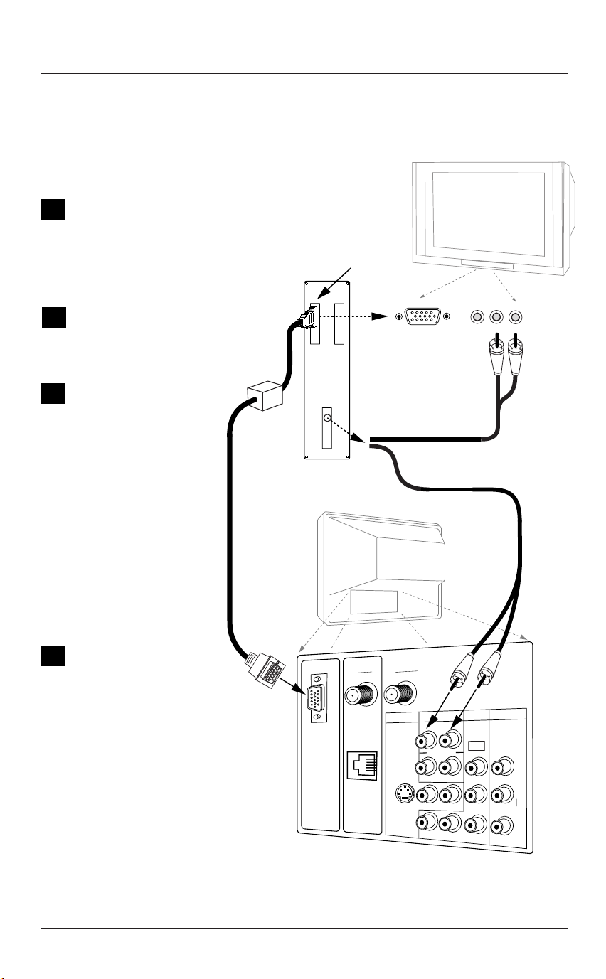
Make the basic con-
1
nections as indicated. (Appearance of
components may vary
from those in the
illustrations.)
Set the computer’s
2
image output settings to 800 x 600 @
60Hz or SVGA.
On the Source menu,
3
highlight “REAR COMPUTER SVGA” (Rear
Computer in) then
press ENTER on the
remote to change to
the computer image
source. Or plug the
computer connector
into “Computer In”
on the TV front
panel. (Note: Item
41-I Auto Compport
must be set to 0 in
the installer menu.)
Video Out to
Computer
Monitor
"Video Mirror"
Cable
Computer Video "Card"
Output
Back of
Computer
Computer Sound
"Card" Output
TV Back
Computer in
TV Front
Video in
R audio L
Boot up your com-
4
puter. As it warms
up, the TV will adapt
to your computer.
Note: Unlike a computer
monitor, this TV does not
show a computer image on
the screen un
completely adapted to your
computer’s output. This is
normal when using this TV
as a computer monitor.
en the TV has complete-
Wh
ly adapted to your computer, the computer’s image
will appear on the screen.
Page 8
til the TV has
ANTENNA
DIGITAL
C
ANTENNA
O
M
P
U
T
E
R
I
N
Connections to TV front or rear computer port,
with computer sound card output
to front or rear R - audio - L inputs.
M.P.I.
IN
CABLE
S-VIDEO
AUDIO
COMPUTER
R
AUDIO OUT
R
R
VIDEO IN
DVD IN
480I
L
Y
B
P
L
L
PR
R
AUDIO
L
Computer Hookup
R audio L
Video in
TV Front
Computer in
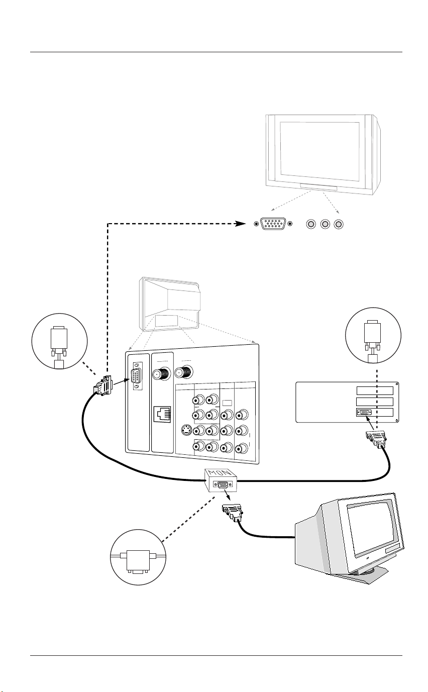
Make the connections with the 15-ft. “Video-Mirror” cable exactly as shown. Also
refer to the preceding page for audio connections and “Using the monitor function.”
An accessory packet is included with
all TV models. A 15-ft. cable with a
“video mirror” for providing a computer image to two monitors—your
computer’s monitor and the TV.
(800 x 600 @60 Hz)
TV
Connect
to
TV
Video-Mirror cable
connectors are clearly
marked.
Connect as shown in drawing:
TV to the Television
MON to the Computer Monitor
PC to the Computer
MON
TV Back
Note: Actual
appearance of
components
may vary.
Connect
to
Computer
ANTENNA
DIGITAL
ANTENNA
M.P.I.
CABLE
S-VIDEO
IN
Connect
to
Monitor
AUDIO
COMPUTER
R
AUDIO OUT
R
R
VIDEO IN
DVD IN
480I
L
Y
R
P
B
L
L
PR
AUDIO
L
Video Cable
from Monitor
Back of
Computer
C
O
M
P
U
T
E
R
I
N
PC
Computer Monitor
Notes
• Your TV must be plugged in—not necessarily turned On—for the computer monitor to function.
• Unless the Mirror Cable is connected exactly as shown above, no computer image will appear on the TV.
Page 9

PC Windows Environment
Setting up your computer for optimum picture output in the Windows operating
system environment
WINDOWS Environment
The following is a step-by-step procedure for setting your computer’s picture output to optimum
display quality.
1. Plug in your computer to the Presentation TV.
Turn On the TV and then the COMPUTER.
2. Open the computer CONTROL PANEL and click on
DISPLAY PROPERTIES.
3. Click on APPEARANCE. This is where you will
make changes for Presentation display.
At this time you will now CREATE a NEW SCHEME or
display for Presentation TV Display. Once you have
created this “new scheme” you’ll be able to quickly
switch between Normal and the Presentation display Scheme. Once you have made the changes to
your computer Scheme, then SAVE AS a Classroom
Display. Use the following steps to change each
ITEM, FONT and COLOR for optimum computer
image viewing on the TV screen.
1. Select under the ITEM and start with ACTIVE
TITLE BAR.
* Select SIZE to 28
* Select COLOR to GREY
* Select FONT
* Select TIMES NEW ROMAN
* Select SIZE 18
* Select COLOR of BLACK
2. Select under the ITEM category CAPTION
BUTTONS
* Select SIZE of 25
3. Select under the ITEM category ICON
* Select SIZE of 40
* Select FONT SIZE of 20
* Select FONT of TIMES NEW ROMAN (BOLD)
Technical Update: Optimum Display, November
1998
4. Select under the ITEM category ICON SPACING
(Horizontal)
* Select SIZE of 100
5. Select under the ITEM category ICON SPACING
(Vertical)
* Select SIZE of 100
6. Select under the ITEM category INACTIVE TITLE
BAR
* Select SIZE of 30
* Select FONT SIZE of 18
* Select FONT of TIMES NEW ROMAN
7. Select under the ITEM category MENU
* Select SIZE of 30
* Select FONT SIZE 18
* Select FONT of TIMES NEW ROMAN
8. Select under the ITEM category MESSAGE BOX
* Select FONT SIZE of 14
* Select FONT of TIMES NEW ROMAN
9. Select under the ITEM category PALETTE TITLE
* Select SIZE of 30
* Select FONT SIZE of 18
* Select FONT of TIMES NEW ROMAN
10. Select under the ITEM category SELECTED
ITEMS
* Select SIZE of 30
* Select COLOR of BLUE
* Select FONT SIZE of 18
* Select FONT of TIMES NEW ROMAN
11. Rename the scheme and SAVE AS,
PRESENTATION DISPLAY.
12. CHANGING THE APPLICATION ICON SIZE
* Select Excel (Spreadsheet/workbooks)
* From the TASK BAR select TOOLS
* Select CUSTOMIZE
* Select OPTIONS
* Click on LARGE ICONS
The Icons within WORD and EXCEL will now match
your new Scheme display.
You have set up your Windows computer for
optimum Presentation TV Display.
Page 10

Macintosh Environment
Setting your computer for optimum picture output in the Macintosh
operating system environment
MACINTOSH Environment
The following is a step-by-step procedure for setting your computer picture output to optimum display quality.
1. Plug your computer in to the Presentation TV.
Turn On the TV and then the COMPUTER.
2. Open your CONTROL PANEL by choosing under
the APPLE icon or by clicking on your HARD
DRIVE icon. If you choose the HARD DRIVE
icon, you’ll have to open your CONTROL PANEL
through the SYSTEMS FOLDER.
3. After you have located the CONTROL PANEL,
click on VIEWS. This is where you will make
changes for Presentation display.
4. Change the FONT to one that is appears well on
a television. We would suggest that you use
TIMES BOLD. Now, change the FONT SIZE to 18
or better.
Each time that you use the TV with your computer, you will simply change the FONT and
SIZE through the CONTROL PANEL and VIEW. You
have changed the appearance of all your folders
but NOT your applications.
VIEWING FOR PRESENTATION vs. PRIVATE
1. When viewing an application, such as EXCEL or
WORD, you will have to change the appearance
of each application.
2. Once the application has been opened, just
change the view from 100 percent to a selection over 150 percent. This will not permanently effect your document. Once you have completed your presentation, simply reduce the size
back down to 100 percent viewing ratio.
3. To enlarge the ICONS of the application, click
on VIEW and then select TOOLBARS. Slide down
and highlight CUSTOMIZE with your mouse, then
click.
4. A file folder will now “pop-up”. Now select
OPTIONS and then click on LARGE ICONS. This
will only enlarge the ICONS on your menu
palette. Due to a less flexible platform, you
will not be able to effect the fonts/size on the
Menu Bar.
This Zenith Presentation TV is a high-quality, low
cost alternative to a true SVGA monitor.
Page 11
Computer Source Selection
Choosing the computer input on the Source menus
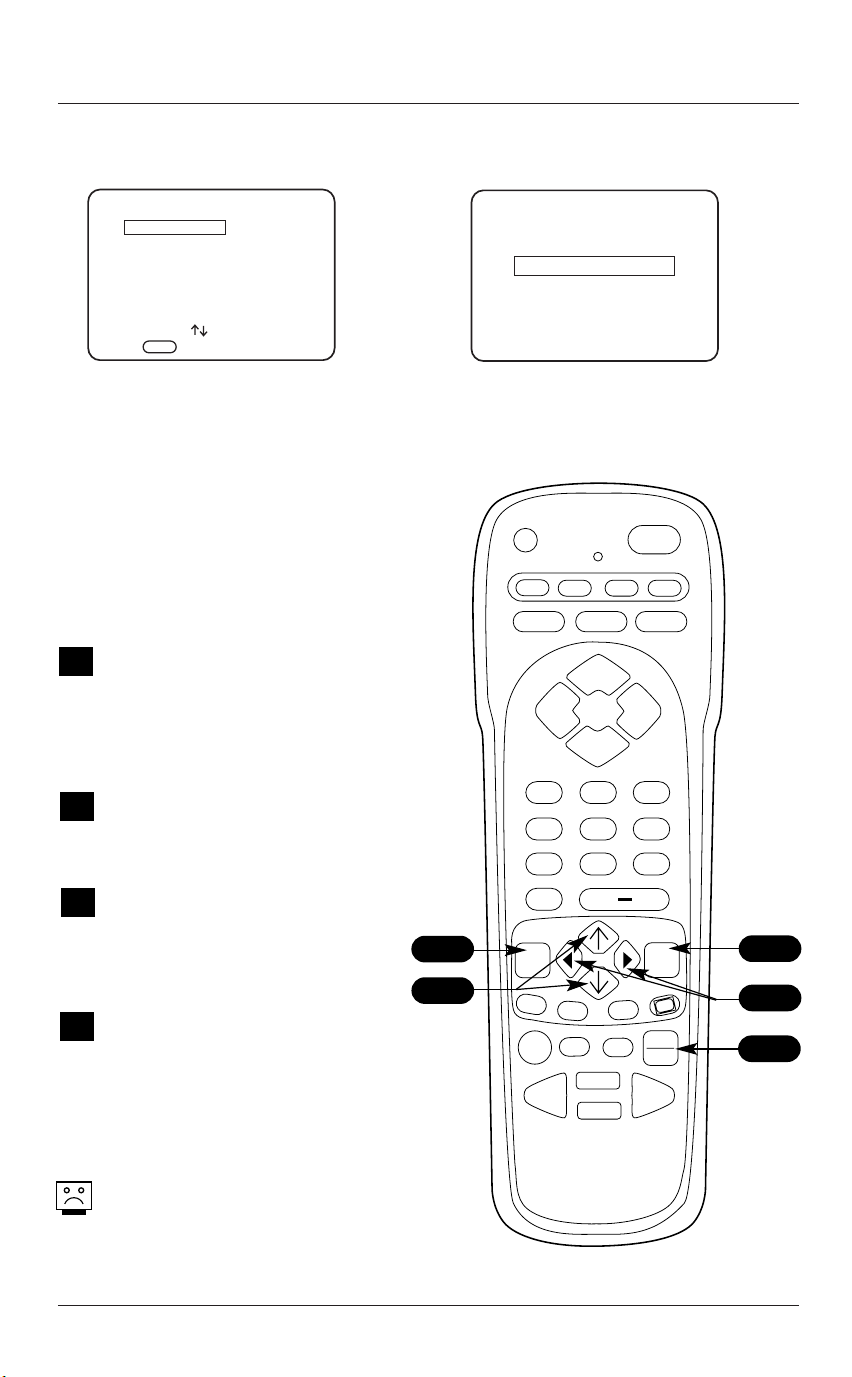
SOURCE MENU
ANTENNA/CABLE
AUX VIDEO
S-VIDEO
FRONT COMPUTER SVGA
REAR COMPUTER SVGA
COMPONENT YPrPb
PRESS TO CHANGE
PRESS ENTER OR
KEYS TO ACTIV.
< >
FRONT COMPUTER SVGA
SOURCE
PRESS:
SOURCE TO CHANGE
ENTER TO ACTIVATE
Selecting Viewing Sources Using
the Onscreen Menus
Selecting Computer Source with Direct
Connection - Auto Source Sensing.
Plug the computer display
15-pin output into the front
Computer In port.
Source Selection Using Remote Control
Press TV/VCR SOURCE repeated-
A
ly on the remote to cycle
through the available sources.
Source Selection Using Source Menu
Press MENU repeatedly on the
1
remote until the Source menu
appears.
Use the Up/Down arrow on the
2
remote control, to select the
computer source that you want
to appear on your screen.
Press Enter, or the Left/Right
3
arrow on the remote, to
change to the new source.
Press ENTER again to remove
menu.
Selecting Viewing Sources Using
TV/VCR Source Key on Remote
PRG
VCR
CABLE
AUDIO
VOLUME VOLUME
123
456
7
0
1
2
MENU
A
B
PAUSE
RECORD
REWIND FFWD
POWER
AUX TV
FLASHBK
CHANNEL
CHANNEL
MUTE
89
ENTER
C
TV/VCR
TIMER
SOURCE
PLAY
STOP
CC
3
3
A
The front panel ‘Computer In’ port is
auto sensing and must be enabled in
the Installer menu before it will appear
in the Source menu. See Installer menu
item 41-I Auto Compport.
Page 12
Computer Video Menu
Use the Computer Video Menu to optimize the picture from the computer
source for best presentation
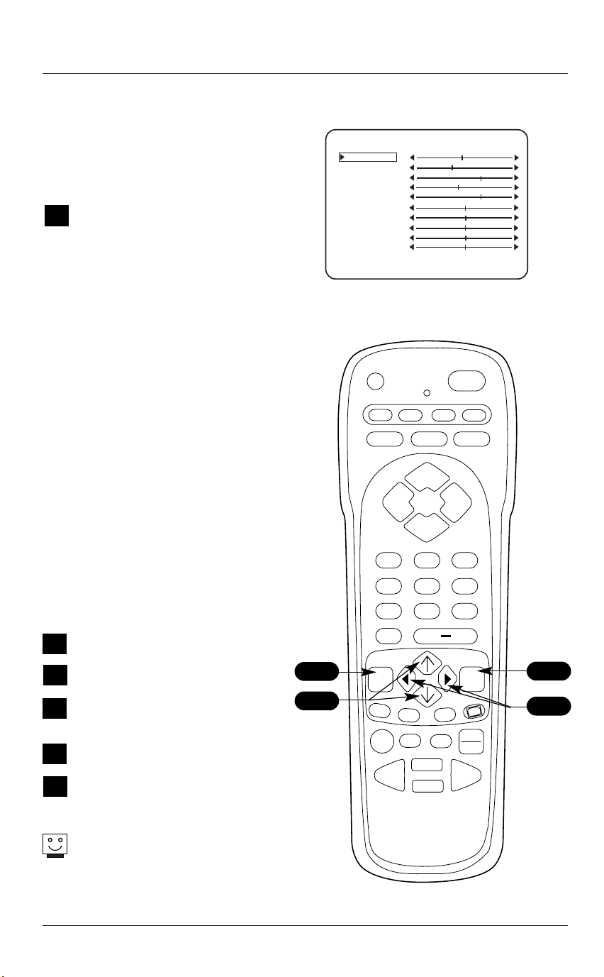
COMPUTER VIDEO MENU
CONTRAST
BRIGHTNESS
RED
GREEN
BLUE
Press the MENU key and repeat to select the
1
Video menu. Available options are:
• Contrast: Adjusts the level of difference
between white and black in the picture. The
more contrast, the brighter the picture
appears.
• Brightness: Increases or decreases
amount of white in the picture.
• Red/Green/Blue: Adjusts the color levels
in the picture.
• Vertical Size: Adjusts the vertical size of
the picture.
• Vertical Position: Adjusts the vertical
position of the picture.
• Horizontal Size: Adjusts the horizontal
size of the picture.
• Horizontal Position: Adjusts the horizontal position of the picture.
• Rotation: Adjusts pictures horizontal axis.
Note: Use TV front panel Volume (Vol)
left/right buttons to correct any tilt.
• Degauss: Removes color impurities.
• Picture Preference: Chooses either
Custom or Preset. Custom allows you to set
the picture the way you want. Preset moves
all the above options back to their original,
factory-set levels.
Using the Up/Down arrow on the remote
2
control, choose Contrast on the menu.
Using the Left/Right arrow, change the con-
3
trast level as preferred.
Press ENTER to remove menu, or repeat from
4
Step 2, to select and alter settings for the
other menu options.
Use the Up/Down arrow to choose the
5
Picture Preference option.
Use the Left/Right arrow, to choose either
6
the original default settings with ‘Preset’, or
modified settings with ‘Custom’.
2/5
VERT. SIZE
VERT. POS.
HORZ. SIZE
HORZ. POS.
ROTATION
DEGAUSS
PICTURE PREF
OFF
PRESET
To display the Computer Video Menu, connect
and select a computer source.
PRG
VCR
CABLE
AUDIO
VOLUME VOLUME
FLASHBK
CHANNEL
CHANNEL
POWER
AUX TV
MUTE
123
456
7
89
0
1
MENU
A
B
PAUSE
RECORD
PLAY
REWIND FFWD
STOP
TIMER
ENTER
CC
C
TV/VCR
SOURCE
4
3/6
Choose the Preset option in Picture Preference
to quickly reset the Computer video menu
options to their original default values.
Page 13

Computer Setup Troubleshooting
Some quick and easy tips to resolving problems when using the Presentation
TV as a Computer Monitor
Symptoms Possible Cause(s) Probable Solution(s) See Page(s)
Computer Image
Poor or no • Poor Connections. -Check all cable connections. 8
computer picture. • TV/Computer not turned On. -Turn TV/Computer On.
• Wrong TV source selected. -Select the proper TV source the computer is
connected to. 12
• 800 x 600 @60 HZ not set. -On the Computer, set display output to
800 x 600 @60 Hz. 9
• TV not adjusted to computer. -Wait until TV adjusts to computer image. 9
• Cable over 25 feet. -Set up Computer/TV where an excessively long
cable is not required.
• Installer menu set incorrectly. -Check Installer menu item 41-I setting. 48
Local interference. • Check for disturbing source. The following may cause image problems or
• Appliance too close to TV -If possible increase the distance between your
or computer. TV, the computer and offending appliance. Or
Fuzzy computer • 800 x 600 @60 HZ not set. -On the computer, set display output to 9
picture. 800 x 600 @60 Hz.
Poor computer • Computer display output is -See page 13 for instructions to optimize
picture. not optimized. computer’s image.
‘Front Computer • Auto Sense Source setup. -Set Installer item 041 to ‘0’ for Front 48
SVGA’ does not Computer SVGA to appear in Source menu.
appear in -Set Installer item 041 to ‘1’ to make the 48
Source menu. front Computer In port Auto Source Sensing.
distortion: Electrical appliances, powerful lights,
cars, trucks; computers or portable phones;
medical equipment.
turn one of them off.
Page 14
L
M.P.I.
C
O
M
P
U
T
E
R
I
N
PR
VIDEO IN
IN
COMPUTER
R
DVD IN
AUDIO
AUDIO
S-VIDEO
AUDIO OUT
R
L
R
L
R
L
Y
P
B
480I
DIGITAL
ANTENNA
ANTENNA
CABLE
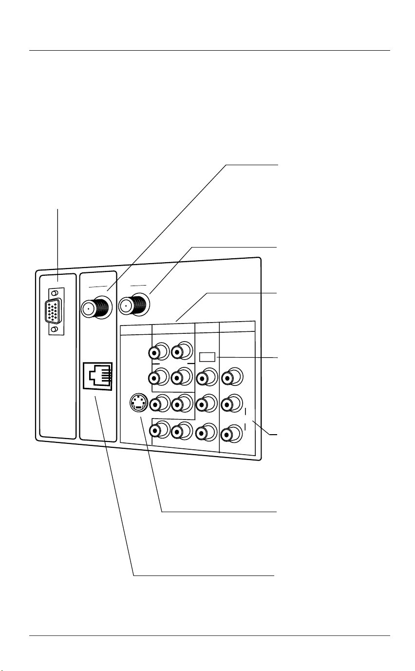
TV Connections Overview
A brief overview of the connections available on this TV
Use this page for reference when connecting analog or digital signal sources and other source equipment.
To hook up source equipment, refer to the next page; shows pages to go to for equipment hookup options.
Also, see the front connection panel hookup options on page 24.
Notes:
• Digital cable program signal processing is not possible with this TV.
• If only one wire provides the signal source, use a standard 2-way signal splitter and connect it to both
the Antenna-Cable and Digital Antenna RF jacks on the TV, see below.
REAR COMPUTER SVGA
Rear Computer input port. Connect your
PC to this port to show computer video
output on the TV screen.
See page 9.
Digital Antenna
Connect if digital signal source
is available.
Note: If both digital and analog
signals are only available from
one RF lead, connect a signal
splitter (not provided).
See page 16.
Antenna/Cable
Connect analog off air antenna
or analog CATV signal source
here. See page 16.
Computer Audio
Connect audio output from your
computer here. See page 8.
Audio Out
Connect to external amplifier.
See page 23.
DVD In
Component Video Inputs
Connect component video
equipment or a DVD player here.
• DVD Player 480i
• Set Top Box 480i
See page 21.
Video In R-Audio-L
Connect composite Video-Audio
source here.
See page 22.
S-Video In R-Audio-L
Connect S-Video-Audio source
here. See page 20.
Note: Key in 132, press Enter to
switch to S-Video source.
MPI Port
Connect LT2002 Quickset II
clone programmer to MPI port.
See page 56.
Page 15
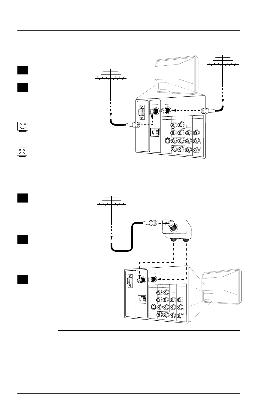
Hook Up Off Air Antennas
Connect over the air signal sources to the TV
Over the Air Antenna
Locate the RF jacks on the
1
back of the TV.
Connect the RF antennas
2
that run from the wall
directly to these jacks
according to the connection
diagram shown to the right.
If you have a 75 ohm RF
cable, then you don’t need
any adapters.
A 300 to 75 ohm adapter is
not included with the Zenith
TV.
Antenna
RF Coaxial Wire
(75ohm)
TV Back
ANTENNA
DIGITAL
C
O
M
P
U
T
E
R
I
N
CABLE
ANTENNA
S-VIDEO
M.P.I.
IN
TV Back Connections Panel
(Expanded View)
AUDIO
COMPUTER
R
AUDIO OUT
R
R
RF Coaxial Wire
VIDEO IN
DVD IN
480I
L
Y
R
P
B
L
AUDIO
L
L
PR
To get digital with only one RF antenna lead, install a two-way signal splitter
If there is only one antenna
1
lead available from the wall
antenna jack, locate the
Antenna/Cable and the
Digital Antenna jacks on the
back of the TV.
Antenna
75 ohm
Signal Splitter
Antenna
(75ohm)
Connect the RF antenna that
2
runs from the wall directly
to a 75 ohm 2-way signal
splitter (not provided),
according to the connection
RF Coaxial Wire
(75ohm)
diagram shown to the right.
ANTENNA
DIGITAL
CABLE
C
ANTENNA
O
M
Connect the two antenna
3
leads to the TV RF inputs:
Antenna/Cable and Digital
Antenna. This will provide
the same over-the-air signal
to both the analog and digital RF inputs.
P
U
T
E
R
I
S-VIDEO
N
M.P.I.
COMPUTER
R
AUDIO OUT
IN
R
R
VIDEO IN
DVD IN
AUDIO
480I
L
Y
R
B
P
L
AUDIO
L
L
PR
TV Back
Mini Glossary
2-Way Splitter A device that provides two antenna signals from one antenna lead.
75 ohm The wire that comes from an off-air antenna or cable service provider. Each end
RF Cable looks like a hex shaped nut with a wire sticking through the middle, and it screws
onto the threaded jack on the back of the TV.
300 to (Not shown) A small device that connects a flat two-wire 300 ohm antenna to a 75
75 ohm ohm RF jack. They are usually about an inch long with two screws on one end and a
Adapter round opening with a wire sticking out on the other end.
Page 16

Hook Up Cable Service (CATV)
Connect cable service to the TV
Cable Service
Locate the Antenna/Cable in jack
1
on the back of the TV set.
Connect the CATV cable that runs
2
from the wall according to the
connection diagram shown to the
right.
The TV digital tuner does not
work with a Digital Cable signal
source.
Cable Service with a Cable Box
Cable TV
Wall Jack
RF Coaxial Wire
(75ohm)
Typical
TV Back
ANTENNA
DIGITAL
ANTENNA
M.P.I.
CABLE
VIDEO IN
DVD IN
AUDIO
S-VIDEO
COMPUTER
480I
L
R
Y
AUDIO OUT
IN
R
L
R
L
R
P
B
AUDIO
L
PR
C
O
M
P
U
T
E
R
I
N
Locate the Antenna/Cable in jack
1
on the back of the TV set.
Connect the CATV cable that runs
2
from the wall to the cable box
and TV according to the connection diagram shown to the right.
If you’re using a cable box, tune
the TV to channel 3 or 4 and use
your cable box to change
channels.
If you’re using a cable box, Auto
Program channel search might
only find the channel the cable
service is on (usually channel 3
or 4).
The TV digital tuner does not
work with a Digital Cable signal
source.
Cable TV
Wall Jack
In
Out
Cable Box
output
switch
RF Coaxial Wire
(75ohm)
3 4
Typical
TV Back
ANTENNA
DIGITAL
ANTENNA
M.P.I.
CABLE
VIDEO IN
DVD IN
AUDIO
S-VIDEO
COMPUTER
480I
L
R
Y
AUDIO OUT
IN
R
L
R
L
R
P
B
AUDIO
L
PR
C
O
M
P
U
T
E
R
I
N
Page 17

Hook Up Off Air Antennas with VCR
Connect over the air signal source to the VCR and TV
Over the Air Antennas with VCR
Locate the Antenna/Cable In jack on the
1
back of the VCR.
Connect the antenna wire that runs from the
2
wall jack directly to this jack, according to
the connection diagram shown to the right.
Connect a 75 ohm off air antenna signal to
3
the Digital Antenna input on the TV for digital programming.
Make the VCR to TV connections as indicated
4
in the illustration.
If you have a 75 ohm RF cable, then you
don’t need any adapters!
A 300 to 75 ohm adapter is not included
with the Zenith TV.
Antenna
VCR Back
VCR Back AV Panel
output
In
switch
Out
Video
Audio
3 4
Off Air
Antenna
RF Coaxial Wire
(75ohm)
RF Coaxial Wire
(75ohm)
Typical
TV Back
ANTENNA
DIGITAL
ANTENNA
CABLE
VIDEO IN
DVD IN
AUDIO
S-VIDEO
COMPUTER
M.P.I.
IN
R
AUDIO OUT
R
R
480I
L
Y
R
P
B
L
AUDIO
A/V cables
L
L
PR
not included
with TV
C
O
M
P
U
T
E
R
I
N
Page 18
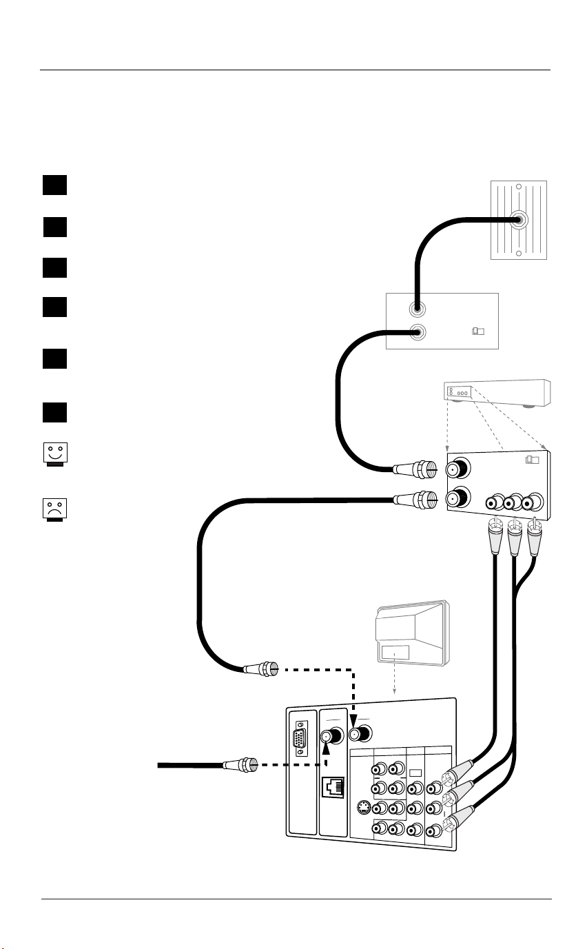
Hook Up a Cable Box with VCR
Connect a cable box and VCR to the TV
Cable Service with VCR
Locate the RF In jacks on the cable box and the
1
VCR.
Connect a 75 ohm cable between the cable box
2
wall jack and Cable In on the cable box.
Connect a 75 ohm cable from the Cable out jack
3
on the cable box to the Ant In jack on the VCR.
Connect a 75 ohm cable between the VCR out
4
jack on the VCR and the Antenna/Cable In jack
on the TV.
Connect 75 ohm off air antenna signal to the
5
Digital Antenna input on the TV to get digital
programming.
Make the other VCR-TV connections as indicated
6
in the illustration.
For cable service without a cable box, connect a
75 ohm cable between the cable wall jack and
the VCR In jack.
The TV digital tuner
does not work with a
Digital Cable signal
source.
In
RF Coaxial Wire
(75ohm)
Out
Cable Box
Output
Switch
Cable TV
Wall Jack
3 4
VCR Back
VCR Back AV Panel
output
In
switch
Video
R - L
Audio
Out
3 4
Off Air
Antenna
RF Coaxial Wire
(75ohm)
Typical
TV Back
ANTENNA
DIGITAL
ANTENNA
M.P.I.
CABLE
VIDEO IN
DVD IN
AUDIO
S-VIDEO
COMPUTER
480I
L
R
Y
AUDIO OUT
IN
R
L
R
L
R
P
B
AUDIO
A/V cables
L
PR
not included
with TV
C
O
M
P
U
T
E
R
I
N
Page 19
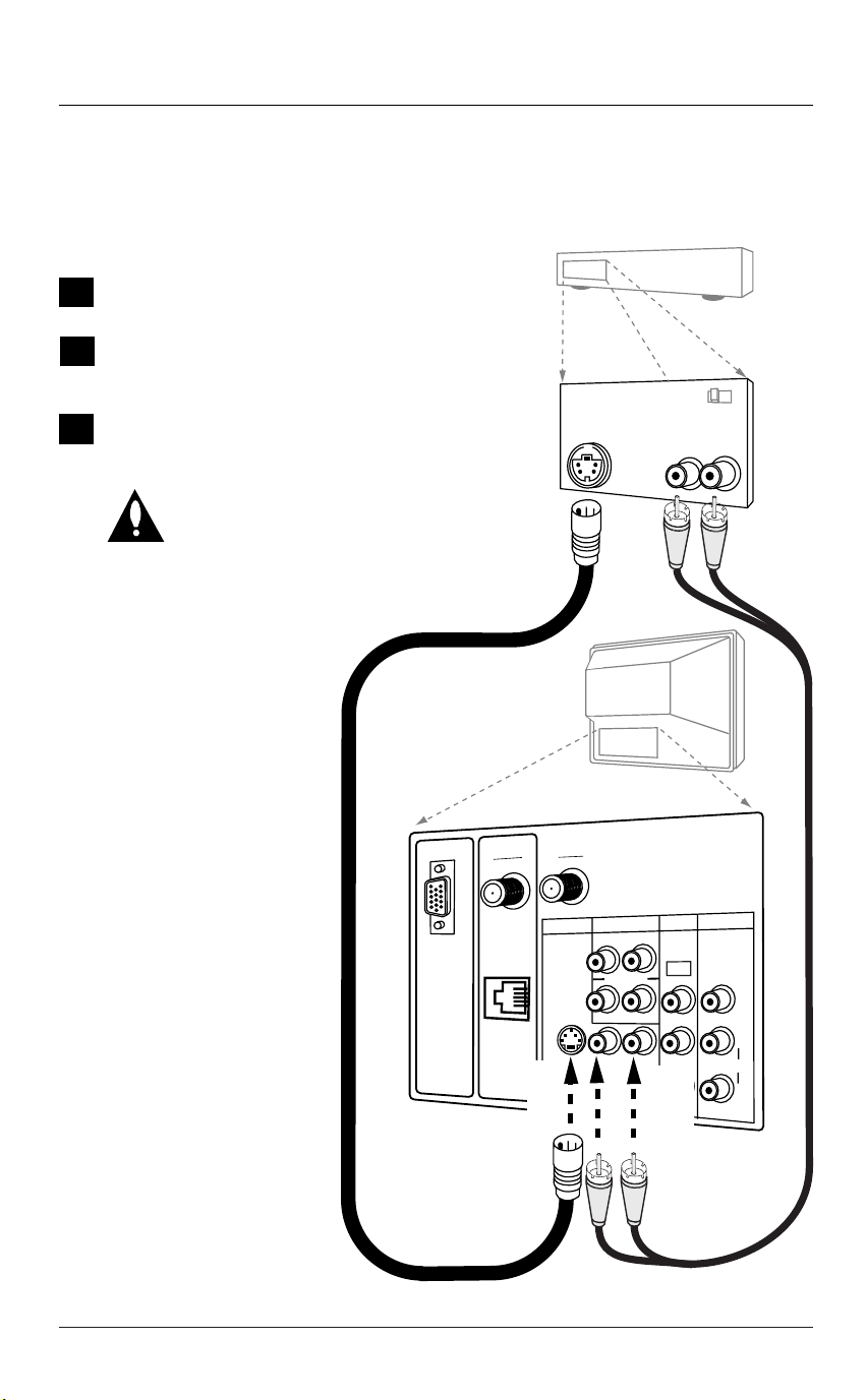
Hook Up S-Video DVD Player or VCR
Connect an S-Video source to the TV
S-Video DVD Player or VCR
Locate the S-Video out jack on the DVD player or
1
VCR.
On the DVD player or VCR, connect the S-Video out
2
jack to the S-Video in jack on the TV according to
the connection diagram shown to the right.
Make the Right/Left audio connections as indicated.
3
IMPORTANT: Key in 132 and Enter on remote control
to show the S-Video Source on the TV
screen. Even though S-Video appears on
Source menu, it can only be accessed by
direct remote keypad entry.
S-Video/R-L Audio
cables are not included
with TV
VCR Back AV Panel
S-Video
Out
VCR Back
Output
Switch
Audio Out
R L
3 4
Typical
TV Back
ANTENNA
DIGITAL
C
ANTENNA
O
M
P
U
T
E
R
I
N
M.P.I.
IN
CABLE
S-VIDEO
AUDIO
COMPUTER
R
AUDIO OUT
R
R
VIDEO IN
DVD IN
480I
L
Y
B
P
L
L
PR
R
AUDIO
L
Page 20
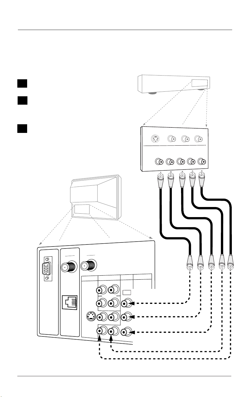
Hook Up DVD Component Video
Connect a Component Video DVD source to the TV
Component DVD Player
Locate the component video out jacks on
1
the DVD player.
On the DVD player, connect component
2
video out jacks to the Component in jacks
on the TV according to the connection diagram shown to the right.
Make the Right/Left Audio connections as
3
indicated.
DVD Player with
Component Video
S-VIDEO OUT
VIDEO
R-AUDIO
L-/MONO
COMPONENT VIDEO OUT
B PR
P
Y
RL
TV Back
IN
ANTENNA
CABLE
S-VIDEO
AUDIO
COMPUTER
R
AUDIO OUT
R
R
VIDEO IN
DVD IN
480I
L
Y
P
B
L
L
PR
R
AUDIO
L
DIGITAL
C
ANTENNA
O
M
P
U
T
E
R
I
N
M.P.I.
Page 21
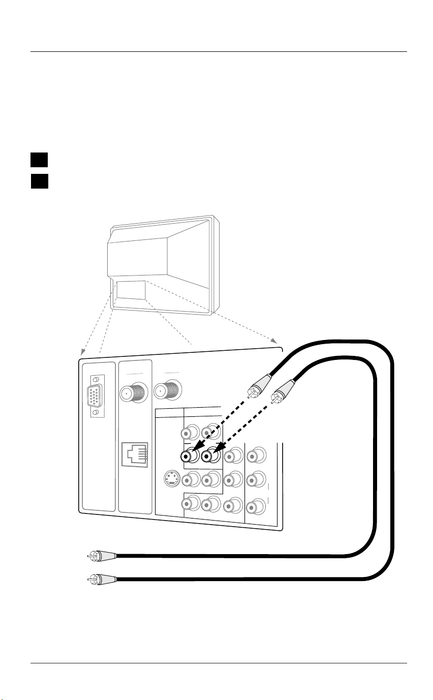
Hook Up Composite Audio/Video
Connect a Composite Audio/Video source to the TV
Composite Audio/Video
Locate the Video In Composite Audio/Video input jacks on the TV.
1
Connect the Composite R-L Audio/Video input jacks on the TV to a
2
composite audio/video source device as shown in the illustration.
Typical
TV Back
Composite
Audio/Video
Device
ANTENNA
DIGITAL
C
ANTENNA
O
M
P
U
T
E
R
I
N
M.P.I.
IN
CABLE
S-VIDEO
AUDIO
COMPUTER
R
AUDIO OUT
R
R
Video/R-L
Audio cables
not included
VIDEO IN
DVD IN
480I
L
Y
B
P
L
L
PR
R
AUDIO
L
with TV
Video Out
Right
Audio Out
Left
Page 22
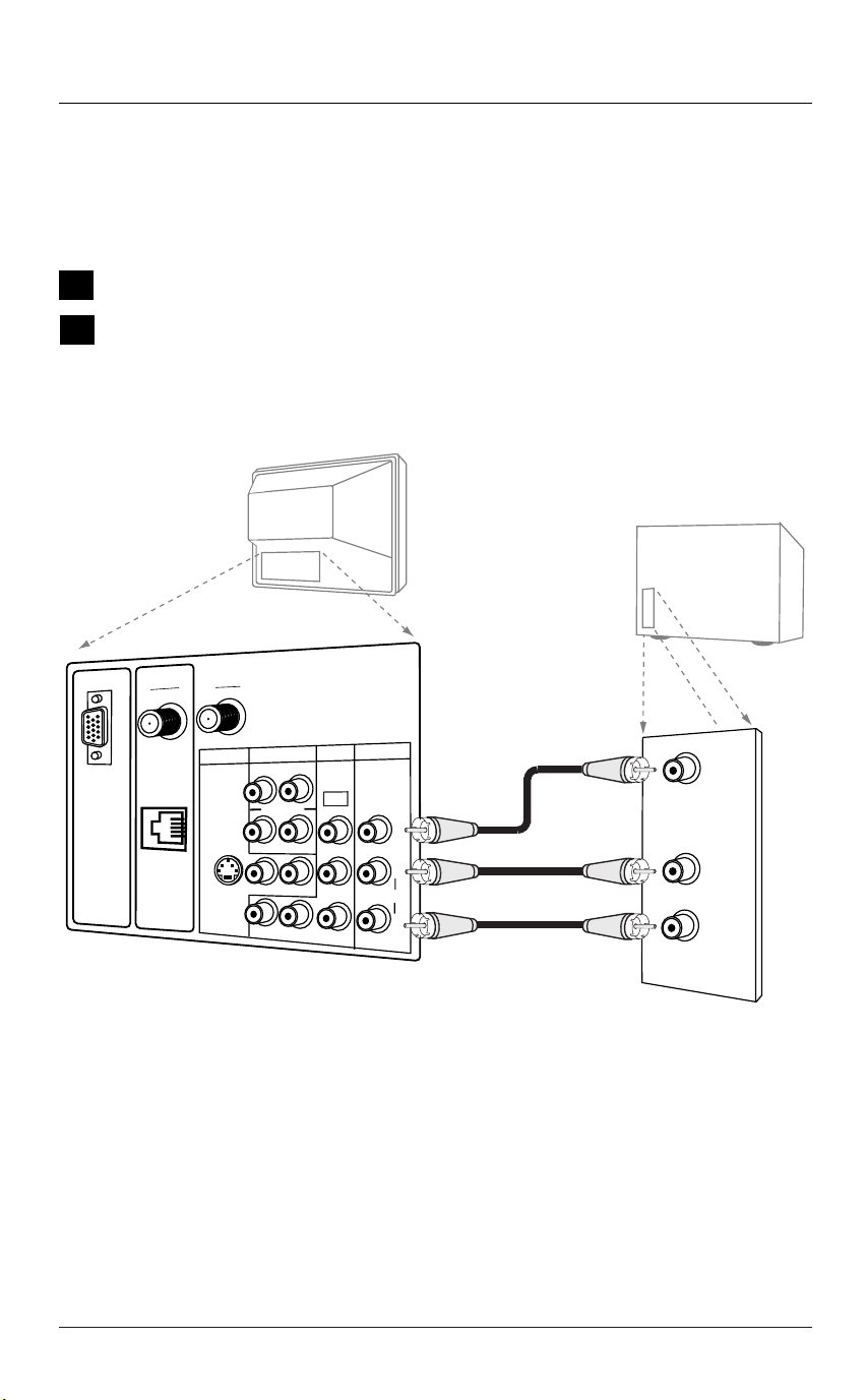
Hook Up an External Speaker
Connect external speakers or audio amplifier to the TV
External Speakers/Audio Amplifier
Locate the R-L Audio Out jacks on the back of the TV.
1
Connect to external speakers or an audio amplifier as indicated in
2
the illustration.
TV Back
Connect
R-L Audio Out
to an external
amplifier and
speakers.
DIGITAL
C
ANTENNA
O
M
P
U
T
E
R
I
N
M.P.I.
ANTENNA
S-VIDEO
IN
CABLE
AUDIO
COMPUTER
R
AUDIO OUT
R
R
VIDEO IN
DVD IN
VIDEO IN
DVD IN
480I
L
Y
B
P
L
L
PR
R
AUDIO
L
Page 23

Front Panel Controls / Auto Sense Source Inputs
power
Typical TV
Front Panel
vol
ch
menu
R-audio-L
Video in
CC
Computer in
D
H
F
G
E
C
B
A
Using the front panel controls to operate the TV/Auto Sensing Connections
Power
A
Turns TV On and Off.
CC (Captions/Text)
B
Turns selected caption/text
option On and Off.
Menu
C
Displays on screen menus.
Vol - Adjust (Left/Right)
D
Decreases/increases
sound level.
Changes menu options.
Ch - Select (Down/Up)
E
Chooses next available
channel.
Selects menu options.
Front Computer Input
F
Port
Connect portable PC here.
Video (In) Camport
G
Input for a video signal
from auxiliary equipment.
L - Audio - R (In)
H
Left/Right Channel audio
input jacks.
Auto Source Sensing
Video In and Computer In on the front panel are auto source
sense inputs. Simply plug an appropriate device into either of
these inputs to have the TV change to the newly-connected
source.
• Installer items 34-I, 40-I and 41-I are set to 1, to enable auto
source sensing.
• To turn Off Auto Source Sensing and show Front Computer SVGA
and Camport in the Source menu, set Installer items 40-I and 41I to 0. Leave item 34-I set to 1.
40-I Camport (Camera Port)
Default is 1=Off. Set to 0 to enable and show as an option in
Source menu.
41-I Compport (Computer Port)
Default is 1=Off. Set to 0 to enable and show as an option in
Source menu.
Source Selection with
Direct Keypad Entry
• Aux Source
Key in 999 and Enter on
remote to access the Aux
Source.
• S-Video Source
Key in 132 and Enter on
remote to access the
S-Video Source.
Page 24
 Loading...