

LG H32H38DT Service Manual

Zenith
SERVICE MANUALSERVICE MANUALSERVICE MANUAL
Product Type:
Chassis
Manual Part #:
Model Line:
Product Year:
Commercial Color TV
CL
3828VD0171F
H
2006
Model Series:
H27H38DT
H32H38DT
Printed in U.S.A.
CONTENTS
General Information/Remote Controls................................
Installer ’s Menu ............................................................
Servicing/Trobleshooting ................................................
Model/Module Parts List .................................................
Exploded Views .............................................................
Schematics ...................................................................
Published by
Technical Publications
Zenith Electronics Corporation
P.O. Box 240007
Huntsville, Al 35824
Copyright March2006 by Zenith Electronics Corporation ©
1
2
3
4
5
6

PRODUCT SAFETY SERVICING GUIDELINES FOR AUDIO-VIDEO PRODUCTS
A
IMPORTANT SAFETY NOTICE
This Manual was prepared for use only by properly trained audio-visual service
technicians. When servicing this product, under no circumstances should the
original design be modified or altered without permission from LG Electronics
Corporation. All components should be replaced only with types identical to
those in the original circuit and their physical location, wiring and lead dress
must conform to original layout upon completion of repairs.
Special components are also used to prevent x-radiation, shock and fire
hazard. These components are indicated by the letter “x” included in their
component designators and are required to maintain safe performance. LG
Electronics Corporation allows no deviations without prior approval. Circuit
diagrams may occasionally differ from the actual circuit used. This way,
implementation of the latest safety and performance improvement changes
into the set is not delayed until the new service literature is printed.
CAUTION: Do not attempt to modify this product in any way. Never perform
customized installations without manufacturer’s approval. Unauthorized modifications will not only void the warranty, but may lead to property damage or
user injury.
Service work should be performed only after you are thoroughly familiar with
these safety checks and servicing guidelines.
GRAPHIC SYMBOLS
The exclamation point within an equilateral triangle is intended
to alert the service personnel to important safety information in
the service literature.
The lightning flash with arrowhead symbol within an equilateral
triangle is intended to alert the service personnel to the presence
of non-insulated “dangerous voltage” that may be of sufficient
magnitude to constitute a risk of electric shock.
The pictorial representation of a fuse and its rating within an
equilateral triangle is intended to convey to the service personnel
the following fuse replacement caution notice:
CAUTION: FOR CONTINUED PROTECTION AGAINST RISK OF FIRE, REPLACE ALL FUSES WITH THE SAME TYPE AND RA TING AS MARKED NEAR
EACH FUSE.
SERVICE INFORMATION
While servicing, use an isolation transformer for protection from AC line
shock. After the original service problem has been corrected, make a check of
the following:
FIRE AND SHOCK HAZARD
1. Be sure that all components are positioned to avoid a possibility of
adjacent component shorts. This is especially important on items transported
to and from the repair shop.
2. Verify that all protective devices such as insulators, barriers, covers,
shields, strain reliefs, power supply cords, and other hardware have been
reinstalled per the original design. Be sure that the safety purpose of the
polarized line plug has not been defeated.
3. Soldering must be inspected to discover possible cold solder joints, solder
splashes, or sharp solder points. Be certain to remove all loose foreign
particles.
4. Check for physical evidence of damage or deterioration to parts and
components, for frayed leads or damaged insulation (including the AC cord),
and replace if necessary.
5. No lead or component should touch a receiving tube or a resistor rated at
1 watt or more. Lead tension around protruding metal surfaces must be
avoided.
6. After re-assembly of the set, always perform an AC leakage test on all exposed
metallic parts of the cabinet (the channel selector knobs, antenna terminals,
handle and screws) to be sure that set is safe to operate without danger of
electrical shock. DO NO T USE A LINE ISOLA TI ON TRANSFORMER DURING THIS TEST .
Use an AC voltmeter having 5000 ohms per volt or more sensitivity in the
following manner: Conn ect a 1500 ohm, 10 watt r esistor, paralleled by .15 mfd
150V AC type capacitor between a known good earth ground (water pipe,
conduit, etc.) and the exposed metallic parts, one at a time. Measure the AC
voltage across the combination of 1500 ohm resistor and .15mfd capacitor.
Reverse the AC plug by using a non-polarized adaptor and repeat AC voltage
measurements for each exposed metallic part. Voltage measured must not
exceed 0.75 volts RMS. This corresponds to 0.5 milliamp AC. Any value
exceeding this limit constitutes a potential shock hazard and must be corrected immediately .
.C. Voltmet e r
Good Earth Ground
such as the Water
Pipe, Conduit, etc.
0.15uF
1500 OHM
10 WATT
Place this probe
on each exposed
metal part.
X-RADIATION
1. Be sure procedures and instructions to all service personnel cover the
subject of x-radiation. The only potential source of x-rays in current TV
receivers is the picture tube. However, this tube does not emit x-rays when
the HV is at the factory-specified level. The proper value is given in the
applicable schematic. Operation at higher voltages may cause a failure of the
picture tube or high-voltage supply and, under certain circumstances may
produce radiation in excess of desirable levels.
2. Only factory-specified CRT anode connectors must be used.
3. It is essential that the service personnel have available an accurate and
reliable high-voltage m eter .
4. When the high-voltage circuitry is operating properly, there is no possibility of an x-radiation problem. Every time a color chassis is serviced, the
brightness should be run up and down while monitoring the high voltage
with a meter, to be certain that the high voltage does not exceed the
specified value and that it is regulating correctly.
5. When troubleshooting and making test measurements in a product with a
problem of excessively high voltage, avoid being unnecessarily close to the
picture tube and the high voltage power supply. Do not operate the product
longer than necessary to locate the cause of excessive voltage.
6. Refer to HV, B+, and shutdown adjustment procedures described in the
appropriate schematics and diagrams (where used).
IMPLOSION
1. All direct view picture tubes are equipped with an integral implosion
protection system; take care to avoid damage during installation.
2. Use only the recommended factory replacement tubes.
TIPS ON PROPER INSTALLATION
1. Never install any receiver in a closed-in recess, cubbyhole, or closely fitting
shelf space over, or close to, a heat duct, or in the path of heated air flow.
2. Avoid conditions of high humidity such as: outdoor patio installations
where dew is a factor, near steam radiators where steam leakage is a factor,
etc.
3. Avoid placement where draperies may obstruct venting. The customer
should also avoid the use of decorative scarves or other coverings that
might obstruct ventilation.
4. Wall- and shelf-mounted installations using a commercial mounting kit must
follow the factory-approved mounting instructions. A product mounted to
a shelf or platform must retain its original feet (or the equivalent thickness
in spacers) to provide adequate airflow across the bottom. Bolts or screws
used for fasteners must not touch any parts or wiring. Perform leakage tests
on customized installations.
5. Caution customers against mounting a product on a sloping shelf or in a
tilted position, unless the receiver is properly secured.
6. A product on a roll-about cart should be stable in its mounting to the cart.
Caution the customer on the hazards of trying to roll a cart with small
casters across thresholds or deep pile carpets.
7. Caution customers against using a cart or stand that has not been listed by
Underwriters Laboratories, Inc. for use with its specific model of television
receiver or generically approved for use with TVs of the same or larger screen
size.
8. Caution customers against using extension cords. Explain that a forest of
extensions, sprouting from a single outlet, can lead to disastrous consequences to home and family.
3828VD0171F DIGITAL CL - SAFETY
i
PRODUCT SAFETY SERVICING GUIDELINES FOR AUDIO-VIDEO PRODUCTS
X-RADIATION
To prevent possible exposure to x-radiation caused by excessive CRT
anode voltage, the Digital CL chassis incorporate a “High Voltage
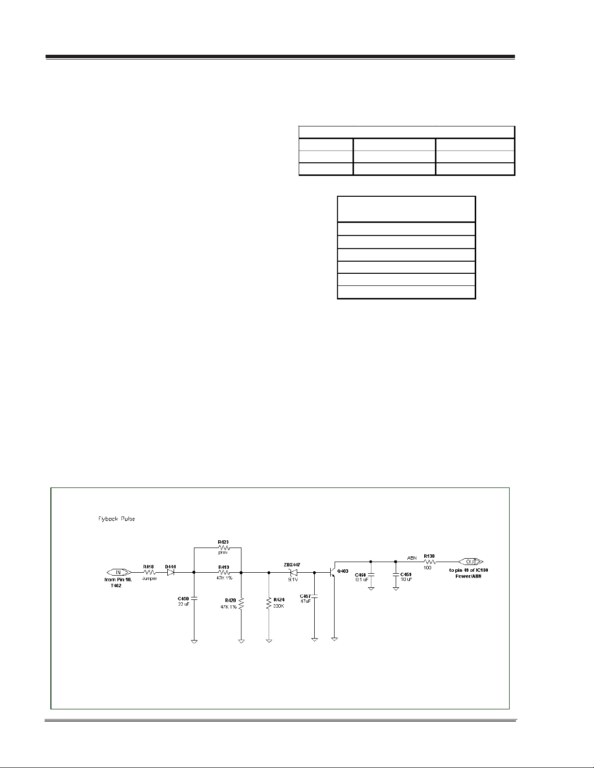
Shutdown” circuit. This circuit senses the level of a flyback pulse
from the “Flyback Transformer” representative of the actual high
voltage on the CRT anode. When this level exceeds a predetermined
voltage, the circuit shuts down the TV set, preventing further generafurther generation of anode voltage.
SHUTDOWN CIRCUIT OPERATION
The flyback pulse voltage from pin 10 of T402 (Flyback Transformer)
is peak detected (rectified) by the action of diode D444 and capacitor C450. This form a DC voltage appearing on C450 representative of the CRT anode voltage (HV) produced by T402. This voltage
is divided down by precision resistors R419, R423, R420 and R424.
This lower voltage appears on the zener diode ZDX447; when this
voltage exceeds by 0.7 Vdc the “zener voltage” Q403 enters in
saturation mode end then the HV shutdown occurs (pin 49 of
IC100).
CRT ANODE HIGH VOLTAGE MEASUREMENT PROCEDURE
Each CRT screen size has it’s own safe operating anode and
shutdown voltage. Critical safety component (designated with
an ‘X’ in the component designator) are designed to operate the
CRT at a safe operating anode voltage and provide proper shutdown thresholds. If replacement of any of these components
are deemed necessary, it is important to use original type LG
Electronics components. After replacement is made, confirm
proper anode voltage using the following procedure.
Measurement of the CRT anode voltage must be performed using a
high impedance-high voltage meter, with no raster on the screen,
and operating at nominal horizontal frequency, 15.75 Khz (NTSC
signal).
After discharging the CRT, connect a high impedance-high voltage
meter to the CRT anode. Turn the television ‘on’ and confirm a good
signal is being displayed. Reduce Brightness and Contrast settings
until the picture is well extinguished.
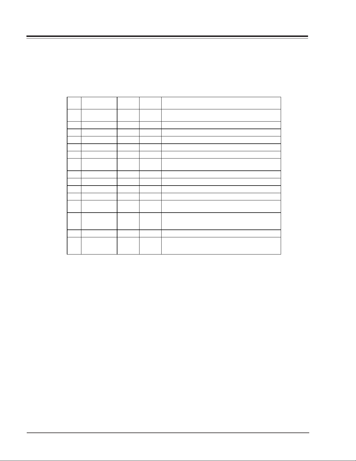
Observe the anode voltage meter reading and compare with the
table below for the proper CRT screen size. If the voltage reading
is higher than the maximum, verify circuit component values and
proper operation.
CRT Anode Voltage
CRT Screen Size Nominal Anode Voltage Max. Shutdown Voltage
(KV) (KV)
27" 30 ± 1.0 36
COMPONENTS WITH ANY INFLUENCE
IN HV INCREASE
Fly-B ack Transformer
Defle ction Yoke
CX404
CX406
CX405
ICX3751
HV SHUTDOWN PROCEDURE.
·After discharging the CRT, connect a high impedance-high voltage meter to the CRT anode
·Remove jumper wire from RX3750.
·Connect a variable Resistor (1 Mohm) in location RX3750.
·Access Video Menu and adjust Brightness and Contrast controls
for minimum screen luminance (beam current to 0 mA).
·Wait until the Video Menu or display disappear.
·Increase (from zero) slowly the resistance value until shutdown
occurs.
·Measure High Voltage shutdown.
3828VD0171F DIGITAL CL - SAFETY
ii
INSTALLERS MENU
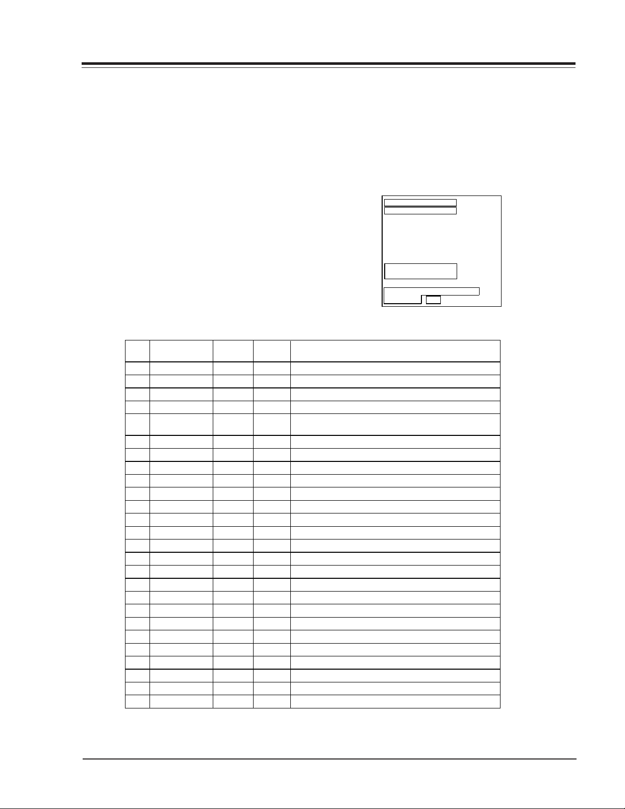
Installer’s menu items can be
accessed by using the optional
installer’s remote control. Just
press and hold MENU (about 8
seconds) until the menu disappears, then press 9, 8, 7, 6,
then ENTER. To remove the
Installer’s Menu, press ENTER
repeatedly. Any changes you
make will be stored in nonvolatile memory.
The Installer’s menu opens with
the main menu. Use MENU and
SELECT to sequence through the
installer menus and submenus.
Use SELECT or TV/FM to scroll
up/down in the menus and sub-
menus. To change a setting use
the Left/Right ADJ keys. Press
ENTER to return to main menu.
Using the Installer’s Menu
Items 0-I - 103-I are accessible
only in the Installer’s Menu.
Their numbers, descriptions,
ranges, factory default settings,
and a place for listing any
changes made on site are given
below and on the following
pages.
The Factory Menu that is intended for qualified service technicians only, is not shown. XX-F
Menu Items (not shown here)
are service type adjustments and
only qualified technicians having specialized test equipment
should access them.
INSTALLERS
INSTALLERS1 4
INSTALLERS2
INSTALLERS3
INSTALLERS4
INSTALLERS5
INSTALLERS6
INSTALLERS7
TV MICRO V2.08
D2A CARD V2.05
D2A CARD 3-4 MICRO COMM
STATUS OK
Typical Installer Menu
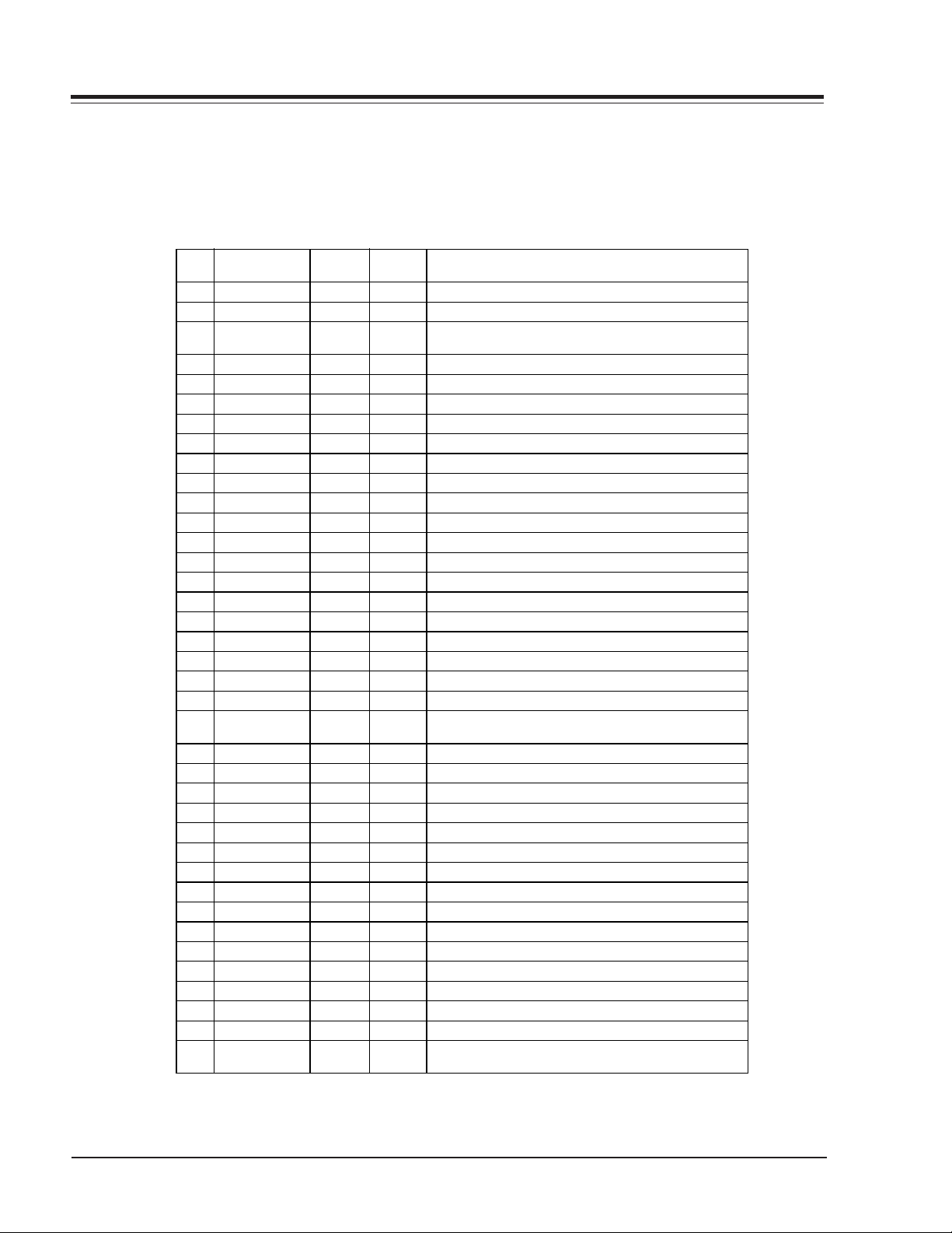
Menu Function Value Default Brief Description of Function and Comments
Item Range Value
0-I. INSTALLER SEQ 0 - 3 0 Leave default set at 0.
1-I. POWER MANAGE 0 - 7 0 Sets number of hours of no activity before auto shutoff.
2-I. AC ON 0 / 1 0 Set to 1 to enable auto turn on at power up.
3-I. BAND-AFC 0 - 7 0 Sets Tuning band.
4-I. STRT CHANNEL 0 - 255 255 Channel at turn-on (255 for last Channel). For digital
channels, use with item 101-I Start Minor Channel.
5-I. CHAN LOCK 0 / 1 0 When set to 1, cannot tune from current channel.
6-I. GHOST CH 0 / 1 0 Set to 1 to enable Ghost Channel display.
7-I. START VOLUME 0-63, 255 255 Volume level at TV turn-on (Set 255 to retain last level).
8-I. MIN VOLUME 0 - 63 0 Minimum volume setting.
9-I. MAX VOLUME 0 - 63 63 Maximum volume setting.
10-I. MUTE DISABLE 0 / 1 0 Set to 1 to disable mute function.
11-I. KEY DEFEAT 0/ 1 1 Set to 1 to disable the front panel keyboard MENU key.
12-I. NOT USED
13-I. SCAN MODE 0 / 1 0 Puts TV On-Off event in Ch Up/Down sequence.
14-I. NOT USED
15-I. SLEEP TIMER 0 / 1 1 Set to 1 to enable Sleep Timer.
16-I. EN TIMER 0 / 1 1 Set to 1 to enable Timer.
17-I. ALARM 0 / 1 1 Set to 1 to enable Alarm.
18-I. NOT USED
19-I. NOT USED
20-I. FEATURE LEVEL 0 / 1 1 Zen 1 Leave default set 1 (1 Zen1).
21-I. V-CHIP 0 / 1 1 Set to 1 to enable V-Chip (Parental Control).
22-I. MAX BLK HRS 0 - 99 12 Sets number of Parental Control blocking hours.
23-I. CAPTION LOCK 0 / 1 0 Set to 1 to retain caption setting at turn off.
24-I. TEXT MODE 0 / 1 1 Set to 1 to add Text option to closed caption menu.
25-I. FUNCTION PRE. 0 - 3 0 Controls channel preview in Pay-Per-View function menu.
Use the Installer Menu to set up or change operational settings.
See detailed descriptions of the Installer Menu items on the following pages
3828VD0171F 2-1 DIGITAL CL - INSTALLERS MENU
INSTALLERS MENU
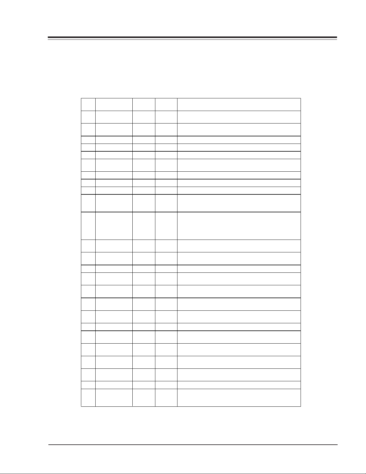
Menu Function Value Default Brief Description of Function and Comments
Item Range Value
26-I. NOT USED
27-I. NOT USED
28-I. CH OVER RIDE 0 / 1 1 When set to 0, limits direct access to favorite channels
and locks Auto Program.
29-I. OLD OCV 0 / 1 0 OCV should set to 1.
30-I. ACK MASK 0 / 1 0 M.P.I. communication parameter.
31-I. POLL RATE 20 - 169 94 M.P.I. communication parameter.
32-I. TIMING PULSE 186 - 227 204 M.P.I . communication parameter.
33-I. NOT USED
34-I. CAMPORT EN 0 / 1 1 Set to 1 to enable the front AUX (Camport ) input.
35-I. SUP. PORT YUV 0 / 1 0 Reserved for future use.
36-I. FRNT Y-C EN 0 / 1 1 Set to 1 to enable the front S-Video input.
37-I. REAR Y-C EN 0 / 1 1 Set to 1 to enable the rear S- Video input.
38-I. YPRPB EN 0 / 1 1 Set to 1 to enable the component input.
39-I. REAR VIDEO EN 0 / 1 1 Set to 1 to enable rear AUX video input.
40-I. AUTO CAMPORT 0 / 1 1 Set to 1 to automatically switch to Camport.
41-I. NOT USED
42-I. AUTO FRNT Y-C 0 / 1 1 Set to 1 to automatically switch to front S-Video input.
43-I. NOT USED
44-I. NOT USED
45-I. NOT USED
46-I. STRT AUX SRCE 0-2, 255 255 Sets the starting AUX source.
47-I. AUX STATUS 0 / 1 0 Set to 1 for M.P.I. AUX source reported as Channel
number instead of Channel 0.
48-I. DIS SETUP M 0 / 1 0 Set to 1 to disable Setup menu.
49-I. DIS AUDIO M 0 / 1 0 Set to 1 to disable Audio menu.
50-I. DIS VIDEO M 0 / 1 0 Set to 1 to disable Video menu.
51-I. DIS VCHIP M 0 / 1 0 Set to 1 to disable V-Chip (Parental Control) menu.
52-I. DIS SOURCE M 0 / 1 0 Set to 1 to disable Source menu.
53-I. DIS CHTIME M 0 / 1 0 Set to 1 to disable Channel-Time on-screen display.
54-I. EN SET COL 0 / 1 0 Set to 1 to enable custom color for the Setup menu.
55-I. FOR SETUP M 0 - 7 6 Custom foreground color for the Setup menu.
56-I. BCK SETUP M 0 - 7 4 Custom background color for the Setup menu.
57-I. EN AUDIO COL 0 / 1 0 Set to 1 to enable custom color for the Audio menu.
58-I. FOR AUDIO M 0 - 7 3 Custom foreground color for the Audio menu.
59-I. BCK AUDIO M 0 - 7 5 Custom background color for the Audio menu.
60-I. EN VIDEO COL 0 / 1 0 Set to 1 to enable custom color for the Video menu.
61-I. FOR VIDEO M 0 - 7 4 Custom foreground color for the Video menu.
62-I. BCK VIDEO M 0 - 7 7 Custom background color for the Video menu.
63-I. EN PTL COL 0 / 1 0 Set to 1 to enable custom color for the V-Chip
(Parental Control) menu.
Installer Menu Items 26-I through 63-I
3828VD0171F 2-2 DIGITAL CL - INSTALLERS MENU
INSTALLERS MENU
Menu Function Value Default Brief Description of Function and Comments
Item Range Value
64-I. FOR PTL M 0 - 7 6 Custom foreground color for the V-Chip
(Parental Control) menu.
65-I. BCK PTL M 0 - 7 4 Custom background color for the V-Chip
(Parental Control) menu.
66-I. EN SRC COL 0 / 1 0 Set to 1 to enable custom color for the Source menu.
67-I. FOR SRC M 0 / 7 3 Custom foreground color for the Source menu.
68-I. BCK SRC M 0 - 7 4 Custom background color for the Source menu.
69-I. EN CHT COL 0 / 1 1 Set to 1 to enable custom color for the
Channel-Time on-screen display.
70-I. FOR CHT COL 0 - 7 1 Custom foreground color for the Channel-Time display.
71-I. BCK CHT COL 0 - 7 1 Custom background color for the Channel-Time display.
72-I. NOT USED
73-I. CH NOT AVBLE 0 / 1 0 When set to 1 and channel over ride is set to 0,
“NOT AVAILABLE” message is displayed when directly
accessing a channel not in the favorite channel list.
74-I. CH-TIME SIZE 0 / 1 0 When set to 1 and transparent background is selected
for Channel-Time display, (foreground color =
background color and custom color enabled) a large
channel number is displayed instead of the normal
Channel-Time on-screen display.
75-I. REVERT CH 0 / 1 0 When set to 1 and loss of M.P.I. communication occurs,
TV tunes to Start Channel.
76-I. DEFEAT XDS 0 / 1 0 When set to 1, XDS display program information
will not appear.
77-I. NOT USED
78-I. UPN MSB 0 - 255 XX User programmable number, most significant byte.
(Line - Day)
79-I. UPN MSB1 0 - 255 XX User programmable number, most significant byte- 1.
(Week)
80-I. UPN MSB2 0 - 255 XX User programmable number, most significant byte- 2.
(SN - HIGH)
81-I. UPN LSB 0 - 255 X User programmable number, least significant byte.
(SN - LOW)
82-I. CHKSM ERROR 0 / 1 1 Enforces rigid M.P.I. checksum.
83-I. HANDSHK TIME 0 - 5 0 Relaxes M.P.I. timing to be compatible with
PC based Windows controlled systems.
84-I. PERMANENT BLK 0 / 1 0 Set to 1 to remove block hours setting for
Parental Control and make blocks permanent.
85-I. A MUTE TIME 0 - 254 35 Controls muting audio delay time when switching
between AUX sources.
86-I. V MUTE TIME 0 - 254 40 Controls muting video delay time when switching
between AUX sources.
87-I. NOT USED
88-I. EN NOISE MUTE 0 / 1 1 When set to 1, the audio signal volume is limited to
a minimum value if no signal is being received from
the broadcaster.
Installer Menu Items 64-I through 88-I
3828VD0171F 2-3 DIGITAL CL - INSTALLERS MENU
INSTALLERS MENU
Menu Function Value Default Brief Description of Function and Comments
Item Range Value
89-I. POKE ENABLE 0 / 1 0 When set to 1, writing to Non - volatile memory
through M.P.I. is enabled.
90-I. KEY LOCK 0 / 1 0 When set to 1, front keyboard functionality is disabled.
91-I. NOT USED
92-I. NOT USED
93-I. NOT USED
94-I. NOT USED
95-I. AUDIO MD DISP 0 / 1 1 When set to 1, Audio Mode Information is enabled to
appear in the Channel Time Display.
96-I. NOT USED
97-I. NOT USED
98-I. NOT USED
99-I. NOT USED
100-I. ATSC TUNE MD 0 / 1 0 Sets ATSC tuning mode. Set to 0 for virtual channel,
set to 1 for physical channel.
101-I. STRT MINOR CH 0 ~ 255 0 Sets the starting minor channel. For NTSC set to 0.
If not 0, sets minor channel number. Set to 255 to
show last tuned channel at turn on.
102-I. NOT USED
103-I. A RATIO LOCK 0 / 1 0 Set to 1, to retain current aspect ratio at turn off.
At turn on, last set aspect ratio will be used. Set to 0 to
reset picture aspect ratio to default at TV turn on.
Installer Menu Items 89-I through 103-I
Detailed Descriptions of Installer
Menu Items
0-I. INSTALLER SEQUENCE
Gives access to Installer Menu depending on the
code selected.
0 = 9876 1 = 4321
2 = 1478 3 = 3698
1-I. POWER MANAGE (Power Management)
Determines hours of no activity before automatic
shutoff. The POWER MANAGE function is for saving
energy. When set to 0, Power Manage is OFF.
Settings range from 0 - 7, with 1 - 7 representing
the hours that the TV will remain on, unless there
has been activity from either the control panel or
remote control.
*M.P.I. Multiple Protocol Input: LG protocol for
remote control of TV through RJ11 (M.P.I.) jack on
TV connections panel.
2-I. AC ON (AC Power Switchable)
Allows the TV to turn ON just by applying AC
power. Pressing the ON button is not necessary.
This is desirable when the TV is plugged into a
cable box or a power outlet controlled by a wall
switch. Use ADJ to select 0 or 1, where 0 is the
default is OFF, and 1 is ON.
Note: When set to 1 (ON), the TV does not
respond to ON/OFF commands from either the
remote or the control panel, and the SLEEP TIMER
is also not functional.
3-I. BAND/AFC (Band/Automatic Frequency
Control)
There are 8 possible settings for this option:
0 = Broadcast Fixed 4 = Broadcast AFC
5 = CATV Fixed 1 = CATV AFC
6 = HRC Fixed 2 = HRC AFC
7 = ICC Fixed 3 = ICC AFC
Channels are accessed faster when fixed modes are
used. The AFC (search modes) should only be used
when some channels are not on nominal frequencies. Note: BAND is automatically set by AUTO
3828VD0171F 2-4 DIGITAL CL - INSTALLERS MENU

INSTALLERS MENU
PROGRAM. If some channels were not found by
AUTO PROGRAM, select the appropriate AFC setting
here and add the channels using the
ADD/DEL/BLNK option in the Setup Menu.
4-I. STRT CHANNEL (Start Channel)
Important: For NTSC start channel, item
101-I STRT MINOR CHANNEL, must be set to
0. When active, this function allows you to
determine the initial channel number when the TV
is turned ON. (To set a digital channel, use with
Item 101 Start Minor Channel.) This feature is useful for an in-house information channel, since the
TV would always select that channel when it is
turned on. Setting this to 255 causes the last
channel viewed when TV was turned Off to be the
tuned to channel when the TV is turned On again.
The range of values is 0 - 255. Use ADJ (Adjust)
keys to choose numbers for the start channel. Start
Channel should be a channel with an active signal.
5-I. CHAN LOCK (Channel Lock)
CHAN LOCK is ideal if a cable box (or similar) is
the sole source for programming—and the TV must
always be on the same channel. Changing channels
with Channel Up/Down or keypad numbers is
impossible. Channel Lock is inactive when set to 0
(default). Generally, this feature is used in conjunction with START CHANNEL (item 4-I.) where
the start channel may, for example, be set to 3 or
4. If the start channel is 3, then the TV will
remain on channel 3.
Note: When CHANNEL LOCK is active and CHANNEL
OVER RIDE is disabled, AUTO PROGRAM is not functional.
6-I. GHOST CH (Ghost Channel)
When set to 1, the current channel number is displayed in the upper right corner of the picture. The
number moves slightly to prevent damage to the
screen. The default is “0” or Off. Note: When captions are On, “Ghost Channel” is not displayed.
7-I. START VOLUME
This function allows the Installer to determine the
initial volume level setting when the TV is turned
ON. This feature is useful for an in-house information channel, since the TV would always select
that Volume level when it is turned on. The range
of values are 0 - 63, 255. If 255 is selected, the
current volume level will be retained in memory
when the TV is turned off. At TV turn on, Volume
level is automatically set to the previous or last
level.
8-I. MIN VOLUME (Minimum Volume)
This function determines the minimum volume
level allowable with the VOLUME (VOL) Up/Down
control. In this way, for example, someone cannot
set the sound too low to hear. The range is from 0
to 63 change values with ADJ (adjust). The factory
default is 0, which provides full range of volume
control. It may be best to set the same value on
every TV.
Note: The minimum volume level cannot have a
value setting higher than in the MAX VOLUME level
(described below).
9-I. MAX VOLUME (Maximum Volume)
This function determines the maximum volume
level allowable with the VOLUME Up/Down control.
In this way, for example, someone cannot set the
sound level high enough to disturb others. The
range is 0 to 63, with 63 as the default which
gives the user the full range of volume control.
Change values with ADJ Left/Right keys. It may be
best to set the same value on every TV.
Note: The maximum volume level cannot have a
value setting lower than the MIN VOLUME level
(See item 8 -I).
10-I. MUTE DISABLE
Enables or disables sound mute function. If set to
1, sound cannot be muted. If set to 0, sound can
be muted.
11-I. KEY DEFEAT
Enables or disables the menu key on the front
panel keyboard. Set to 0 to enable, set to 1 to disable. If set to 1, Key lock appears if MENU key on
front panel is pressed.
12-I. NOT USED
13-I. SCAN MODE
Allows variation in the On/Off setup with CHANNEL
Up/Down. You may opt for TV channels only or TV
channels + Off/On with the following settings for
Scan Mode. Scan mode Characteristics:
0 = Channel Up/Down keys Change channels only.
1 = Channel Down below the lowest channel (or
channel up higher than the highest channel) and
the TV turns off.
Detailed Descriptions for Installer Menu Items 4-I through 13-I
3828VD0171F 2-5 DIGITAL CL - INSTALLERS MENU

INSTALLERS MENU
14-I. NOT USED
15-I. SLEEP TIMER
When set to 1, the Sleep Timer feature is available
to the user (but no message is displayed prior to
turn-off). When set to 0, the Sleep Timer is not
functional.
16-I. EN. TIMER
Set to 1, On/Off Timer functions are available to
end user. Set to 0 to disable Timer functions.
Note: Clock must be set in order to use Timers.
17-I. ALARM
Gives you the option of making the Alarm function
available to the user. Set to 1, Alarm function is
available to user. Set to 0 to disable the Alarm
function. Note: Clock must be set in order to set
the Alarm.
18-I. NOT USED
19-I. NOT USED
20-I. FEATURE LEVEL
Default set to ZEN 1 for Zenith IR remote control
operation. Set O, P LBL for Zenith Private Label IR
remote control operation. WARNING: Do not
change the default value unless you have the proper remote control to operate the TV.
21-I. V-CHIP
Set to 1 to activate V-Chip (Parental Control); have
it available to user to filter or control or restrict
programming content. Set to 0 to turn V-Chip feature off, not available to user; no programming
restrictions can be set.
22-I. MAX BLK HRS
Set 0 to 99 for the maximum V-Chip (Parental
Control) block hours. Default setup is for 12 blocking hours.
23-I. CAPTION LOCK
Set to 1 to restore previous Caption On/Off state
after TV turns Off. When set to 0, Captions are
always Off, when TV is initially turned On.
24-I. TEXT MODE
Determines whether TEXT 1, TEXT 2, TEXT 3, or
TEXT 4 decoding is enabled when TEXT is turned on
(either from the Setup Menu or directly with CC on
the remote).
TIP: Set Text Mode to 1 only if text is offered in
your video system.
25-I. FUNCTION PRE
Set to 0 to suppress CHANNEL PREVIEW from the
FUNCTION menu with some Pay-Per-View systems.
26-I. NOT USED
27-I. NOT USED
28-I. CH. OVER RIDE (Channel Override)
When set to 1, the user can select channels with
either Channel Up/Down or by direct keypad entry.
When set to 0, only those channels that are
entered for scanning may be selected by direct
keypad entry. Note: If set to 0, Auto Program is
locked; (as shown on Setup menu) channel search
is not available.
29-I. OLD OCV (On Command Video
TM
)
Set to 1 for operation with systems from On
Command Corporation.
30-I. ACK MASK
M.P.I. Communication Parameter. Leave at
default setting unless changed by Pay-Per-View
provider.
31-I. POLL RATE
M.P.I. Communication Parameter. Leave at default
setting unless changed by Pay-Per-View provider.
32-I. TIMING PULSE
M.P.I. Communication Parameter. Leave at default
setting unless changed by Pay-Per-View provider.
33-I. NOT USED
34-I. CAMPORT ENABLE
Set to 1 to enable the front AUX (Camport)
input. Set to 0 to disable front AUX input.
35-I. SUP. PORT YUV
Reserved for future use.
36-I. FRONT Y-C EN.
Set to 1 to enable the front S-Video input.
Set to 0 to disable front S-Video input.
Detailed Descriptions for Installer Menu Items 14-I through 36-I
3828VD0171F 2-6 DIGITAL CL - INSTALLERS MENU

INSTALLERS MENU
Detailed Descriptions for Installer Menu Items 37-I through 59-I
37-I. REAR Y-C EN.
Set to 1 to enable the rear S-Video input.
Set to 0 to disable the rear S-Video input.
38-I. YPrPb EN.
Set to 1 to enable rear Component Video input. Set
to 0 to disable rear Component Video input.
39-I. REAR VIDEO EN.
Set to 1 to enable rear AUX (Video) input.
Set to 0 to disable rear AUX input.
40-I. AUTO CAMPORT
Set to 1 to automatically switch to Camport when
equipment is connected to front Video input. Set
to 0 to disable front Video automatic source selection. Note: If disabled, do not connect any jacks.
41-I. NOT USED
42-I. AUTO FRONT Y-C
Set to 1 to automatically switch viewing source to
front S-Video input if equipment is connected.
Set to 0 to disable front S-Video auto source selection. Note: If disabled, do not connect any jacks.
43-I. NOT USED
44-I. NOT USED
45-I. NOT USED
46-I. STRT AUX SRCE
Sets the starting AUX source.
47-I. AUX STATUS
Set to 1 for M.P.I. AUX source to be reported as a
channel number instead of channel 0. Set to 0 to
disable AUX identification change.
48-I. DIS SETUP M
Set to 1 to disable the Setup menu. Setup menu
will not appear. Set to 0 to enable the Setup
menu.
49-I. DIS AUDIO M
Set to 1 to disable the Audio menu. Audio menu
will not appear. Set to 0 to enable the Audio
menu.
50-I. DIS VIDEO M
Set to 1 to disable the Video menu. Video menu
will not appear. Set to 0 to enable the Video
menu.
51-I. DIS VCHIP M
Set to 1 to disable V-Chip menu. V-Chip menu will
not appear. Set to 0 to enable the V-Chip menu.
52-I. DIS SOURCE M
Set to 1 to disable Source menu. Source menu will
not appear. Set to 0 to enable the Source menu.
53-I. DIS CH-TIME
Set to 1 to disable the Channel-Time display.
Channel-Time display will not appear.
Set to 0 to enable the Channel-Time display.
54-I. EN SET COL
Set to 1 to enable custom color settings for the
Setup menu. Set to 0 to disable custom color settings for the Setup menu.
55-I. FOR SETUP M (Setup Menu Foreground
Color)
Set according to Color Chart.
0 = Black 3 = Yellow 6 = Cyan
1 = Red 4 = Blue 7 = White
2 = Green 5 = Violet
56-I. BCK SETUP M (Setup Menu Background
Color)
0 = Black 3 = Yellow 6 = Cyan
1 = Red 4 = Blue 7 = White
2 = Green 5 = Violet
57-I. EN AUDIO COL
Set to 1 to enable custom color settings for the
Audio menu. Set to 0 to disable custom color settings for the Audio menu.
58-I. FOR AUDIO COL (Audio Menu Foreground
Color)
0 = Black 3 = Yellow 6 = Cyan
1 = Red 4 = Blue 7 = White
2 = Green 5 = Violet
59-I. BCK AUDIO COL (Audio Menu Background
Color)
0 = Black 3 = Yellow 6 = Cyan
1 = Red 4 = Blue 7 = White
2 = Green 5 = Violet
3828VD0171F 2-7 DIGITAL CL - INSTALLERS MENU

INSTALLERS MENU
Detailed Descriptions for Installer Menu Items 60-I through 75-I
60-I. EN VIDEO COL
Set to 1 to enable custom color settings for the
Video menu. Set to 0 to disable custom color settings for the Video menu.
61-I. FOR VIDEO M (Video Menu Foreground
Color)
0 = Black 3 = Yellow 6 = Cyan
1 = Red 4 = Blue 7 = White
2 = Green 5 = Violet
62-I. BCK VIDEO COL (Video Menu Background
Color)
0 = Black 3 = Yellow 6 = Cyan
1 = Red 4 = Blue 7 = White
2 = Green 5 = Violet
63-I. EN PTL COL
Set to 1 to enable custom color settings for the VChip menu. Set to 0 to disable custom color settings for the V-Chip menu.
64-I. FOR PTL M (V-Chip Menu Foreground
Color)
0 = Black 3 = Yellow 6 = Cyan
1 = Red 4 = Blue 7 = White
2 = Green 5 = Violet
65-I. BCK PTL M (V-Chip Menu Background
Color)
0 = Black 3 = Yellow 6 = Cyan
1 = Red 4 = Blue 7 = White
2 = Green 5 = Violet
66-I. EN SRC COL
Set to 1 to enable custom color for the Source
menu. Set to 0 to disable custom color for the
Source menu.
67-I. FOR SRC M (Source Menu Foreground
Color)
0 = Black 3 = Yellow 6 = Cyan
1 = Red 4 = Blue 7 = White
2 = Green 5 = Violet
68-I. BCK SRC M (Source Menu Background
Color)
0 = Black 3 = Yellow 6 = Cyan
1 = Red 4 = Blue 7 = White
2 = Green 5 = Violet
69-I. EN CH-T COL
Set to 1 to enable custom color for the ChannelTime display. Set to 0 to disable custom color for
the Channel-Time display.
70-I. FOR CH-T COL (Channel-Time Display
Foreground Color)
0 = Black 3 = Yellow 6 = Cyan
1 = Red 4 = Blue 7 = White
2 = Green 5 = Violet
Note: If foreground and background color are the
same, menu background is transparent.
71-I. BCK CH-T COL (Channel-Time Display
Background Color)
0 = Black 3 = Yellow 6 = Cyan
1 = Red 4 = Blue 7 = White
2 = Green 5 = Violet
Note: If foreground and background color are the
same, menu background is transparent.
72-I. NOT USED
73-I. CH NOT AVBLE
When set to 1 and channel override is set to 0,
“NOT AVAILABLE” message is displayed when
directly accessing a channel not in the favorite
channel list. (Applies to NTSC Channels Only.)
74-I. CH-TIME SIZE
When set to 1 and transparent background is
selected for Channel-Time display, (foreground
color = background color and custom color
enabled) a large channel number is displayed
instead of the normal Channel-Time display.
75-I. REVERT CH
When set to 1 and loss of M.P.I. communication
occurs, TV automatically tunes to the specified
Start Channel.
3828VD0171F 2-8 DIGITAL CL - INSTALLERS MENU

INSTALLERS MENU
Detailed Descriptions for Installer Menu Items 76-I through 103-I
76-I. DEFEAT XDS
Set to 1 to disable XDS display. Set to 0 to enable
XDS display. XDS data (provided at the discretion
of the broadcaster), is available only on analog
channels. After a channel change, wait 5 seconds
then press ENTER to see XDS data, if available.
77-I. NOT USED
78-I. UPN MSB
User programmable number, most significant byte
readable by M.P.I. command.
79-I. UPN MSB-1
User programmable number, most significant
byte-1 readable by M.P.I. Command.
80-I. UPN MSB-2
User programmable number, most significant
byte-2 readable by M.P.I. command.
81-I. UPN LSB
User programmable number, least significant
byte readable by M.P.I. command.
82-I. CHKSM ERROR
Enforces rigid M.P.I checksum validation.
Set to 1 for validation.
Set to 0 to turn off.
83-I. HANDSHK TIME
Adds an additional delay to the handshake time
which is 64 msec, thus relaxing M.P.I. timing
requirements to be compatible with PC based
Windows controlled systems, range is 0 - 5.
Set to 0 to retain standard 64 msec delay.
Set to 1 - 5 to increase @ 16 msec ea., the delay
up to 144 msec.
84-I. PERMANENT BLK
Allows Parental Control blocking schemes to be
permanent by removing the blocking hours function. Set to 1 to install Parental Control blocking
restrictions permanently. Set to 0 for user-specified
hours control of blocking schemes.
85-I. A MUTE TIME
Controls audio muting delay time when switching
between AUX sources. Range is 0 to 254 msec.
86-I. V MUTE TIME
Controls video muting delay time when switching
between AUX sources. Range is 0 to 254 msec.
87-I. NOT USED
88-I. EN NOISE MUTE
When set to 1, the audio signal volume is limited
to a minimum value while receiving no signal from
the broadcaster.
89-I. POKE ENABLE
When set to 1, writing to Non-volatile Memory thru
M.P.I. Is enabled.
90-I. KEY LOCK
When set to 1, front keyboard functionality is disabled. When set to 0, keyboard is enabled.
91-I. NOT USED
92-I. NOT USED
93-I. NOT USED
94-I. NOT USED
95-I. AUDIO MD DISP
When set to 1, Audio Mode Information is enabled
to appear as part of the Channel-Time Display.
96-I. NOT USED
97-I. NOT USED
98-I. NOT USED
99-I. NOT USED
100-I. ATSC TUNE MD (ATSC Tuning Mode)
Sets ATSC tuning mode. Set to 0 for virtual channel, set to 1 for physical channel.
101-I. STRT MINOR CH (Start Minor Channel)
Sets the starting minor digital channel number. For
NTSC set at 0. Not 0, sets digital minor start channel number. Used with item 4-I Start Channel. Set
the major channel number in 4-1 and the minor
digital dash number in item 101-I. At TV turn on,
start channel number is automatically tuned in.
Set to 0 if item 4-I is set to 255 for last tuned
channel.
102-I. NOT USED
103-I. A RATIO LOCK (Aspect Ratio Lock)
When set to 1, current picture aspect ratio is
retained at power off. At power on, previous
aspect ratio will be used. If set to 0, resets aspect
ratio to default setting at TV turn on.
3828VD0171F 2-9 DIGITAL CL - INSTALLERS MENU

FACTORY MENU
DEFLECTION 1
0-F VL (Vertical Linearity)
Adjust so that the boundary line between upper and
lower half is in accord with geometric horizontal center
of the CPT.
1-F VA (V ertical Amplitud)
Adjust so that the circle of a digital circle pattern may
be located within the effective screen of the CPT.
2-F SC (Vertical S-Correction)
Adjust so that all distance between each horizontal lines
are to be the same.
3-F VS (Vertical Shift)
Adjust so that the horizontal center line of a digital
circle pattern is in accord with geometric horizontal
center of the CPT.
4-F HS (Horizontal Shift)
Adjust so that the vertical center line of a digital circle
pattern is in accord with geometric vertical center of
the CPT.
TH
13-F CRNL6 (Lower Corner(6
))
More detail adjusts until symmetries lower corner of the
screen.
DEFLECTION 2
14-F EHTTH (EHT Compensation Threshold)
Threshold for second gains of static horizontal and
vertical EHT compensation.
15-F EHT S (EHT Static Time constant)
EHT Static time constant for horizontal and vertical
amplitude compensation.
16-F EHTV1 (Static V ertical Comp. (1st Gain))1st Gain
for Static Vertical Amplitude Compensation +/-100%,
for beam current<EHT_THRES.
17-F EHTV2 (Static Vertical Comp. (2
2nd Gain for Static Vertical Amplitude Compensation
+/-100%, for beam current>EHT_THRES.
18-F EHTH1 (Dynamic Horizontal Comp. (1st Gain))
1st Gain for Dynamic Horizontal Amplitude Compensation
+/-100%, for beam current<EHT_THRES.
nd
Gain))
5-F EW (Horizontal Width)
Adjust to that a digital circle pattern looks like exact
circle.
6-F ET (East-west Trapezium)
Adjust to make the length of top horizontal line same
with it of the bottom horizontal line.
7-F EP (East-west Parabola)
Adjust so that middle portion of the outermost left and
right vertical line looks like parallel with vertical lines
of the CPT.
8-F CRNU (Upper Corner)
Adjust until symmetries upper corners of the screen.
9-F CRNL (Lower Corner)
Adjust until symmetries lower corners of the screen.
10-F BOW
Adjust the left and right crooked line on upper and
lower side.
11-F ANGLE
Adjust the vertical slope.
12-F CRNU6 (Upper Corner(6TH))
More detail adjusts until symmetries upper corner of
the screen.
19-F EHTH2 (Dynamic Horizontal Comp. (2nd Gain))
2nd Gain for Dynamic Horizontal Amplitude Compensation
+/-100%, for beam current>EHT_THRES.
20-F EHT F (EHT Dynamic Time constant)
21-F EHTP1 (1st Gain for Dynamic Horizontal Phase)
1st Gain for Dynamic Horizontal Phase Compensation +/
-100%, for beam current<EHT_THRES.
22-F EHTP2 (2nd Gain for Dynamic Horizontal Phase)
2nd Gain for Dynamic Horizontal Phase Compensation
+/-100%, for beam current>EHT_THRES.
23-F OSD P
Horizontal Position for menus.
VIDEO-FI 1
24-F CLMPST
Clamping Measurement Start 1. Start of Clamping
Measurement pulse for the ADC1. Range : 0 to 63.
25-F PLLTC
Horizontal PLL Time Constant. Range : 0 to 3.
26-F YC DELAYRF
Luminance Delay for RF input source. Range : -8 to 7.
3828VD0171F 2-10 DIGITAL CL - FACTORY MENU

FACTORY MENU
27-F TINT RF
Internal Tint Control for RF input source. Range : -128
to 127.
28-F SCADJ
Chroma Sub-Carrier adjust register. Range : 0 to 63.
29-F AGCMD
Automatic Gain Control Method. Range : 0 to 3.
30-F ACCLIMRF
Automatic Color Control Limitation for RF input source.
Range : 0 to 31.
31-F CLRANGE
Chroma Lock Range register. Range : 0 to 3
32-F CDYUVIN
Color Decoder YUV input. Range : 0 to 1.
33-F CDYUVTNT
Color Decoder YUV Tint Control for YUV input Source.
Range : -256 to 255.
34-F DISCOMB
Disable or enable the Comb Filter. Range : 0 to 1.
42-F AGCADJ1
Manual AGC Adjust for ADC1. Range : 0 to 63.
43-F AGCADJ2
Manual AGC Adjust for ADC2. Range : 0 to 63.
44-F YUVMAT
Color Matrix for component input. Range : 0 to 2.
45-F YUV TINT
Tint Control for YUV input. Range : -63 to 63.
46-F YUV BRT
Brightness Control for YUV input. Range : -128 to 127.
47-F YUV CON
Contrast Control for YUV input. Range : 0 to 63.
48-F RG YPBPR
Red Gain offset for YPbPr input. Range : 0 to 511.
49-F BG YPBPR
Blue Gain offset for YPbPr input. Range : 0 to 511.
50-F GG YPBPR
Green Gain offset for YPbPr input. Range :0 to 511.
35-F VDG
Vertical Difference Gain to reduce Hanging dots.
Range : 0 to 3.
36-F HDG
Horizontal Difference Gain to reduce Cross-Luminance.
Range : 0 to 3.
37-F VPK
Vertical Peaking Gain. Range : 0 to 15.
38-F REMDEL2
Comb Filter Compensation Delay for ADC2. Range : 0
to1.
VIDEO-FI 2
39-F REMDEL1
Comb Filter Compensation Delay for ADC1.
Range : 0 to 1.
40-F INCOMB
Comb Filter Input Select. Range : 0 to 2.
41-F YCTCOMB
YC through Comb Filter. Range 0 to 1.
51-F RC YPBPR
Red Cutoff offset for YPbPr input. Range : 0 to 511.
52-F BC YPBPR
Blue Cutoff offset for YPbPr input. Range : 0 to 511.
53-F GC YPBPR
Green Cutoff Offset for YPbPr input. Range:0 to 511.
VIDEO-FI 3
54-F YPBPROFS
Internal Brightness offset for YPbPr input. Range : 0 to
511.
55-F YFDEL
Luminance/Fast Blanking Delay for YPbPr input.
Range : 0 to 127.
56-F UVDEL
PbPr Chroma Components Delay. Range : 0 to 127.
57-F USA TADJ
Pb Chroma component saturation adjust. Range : 0 to
63.
3828VD0171F 2-11 DIGITAL CL - FACTORY MENU
 Loading...