

LG GR-P207, GR-C207, GR-B207, GR-L207 Service Manual
CAUTION
PLEASE READ CAREFULLY THE SAFETY PRECAUTIONS OF THIS BOOK
BEFORE CHECKING OR OPERATING THE REFRIGERATOR.
REFRIGERATOR
SERVICE MANUAL
Ref No :
GR-L207
Ref No :
GR-C207
Ref No :
GR-B207
Ref No :
GR-P207
http://biz.lgservice.com

WARNINGS AND PRECAUTIONS FOR SAFETY ................................................................................................................ 3
SPECIFICATIONS................................................................................................................................................................... 4
PARTS IDENTIFICATION ........................................................................................................................................................8
HOW TO INSTALL THE REFRIGERATOR .......................................................................................................................... 14
HOW TO ADJUST DOOR HEIGHT OF THE REFRIGERATOR ........................................................................................ 14
HOW TO INSTALL WATER PIPE........................................................................................................................................15
HOW TO CONTROL THE AMOUNT OF WATER SUPPLIED TO THE ICEMAKER ......................................................... 19
MICOM FUNCTION .............................................................................................................................................................. 21
EXPLATION FOR MICOM CIRCUIT..................................................................................................................................... 31
EXPLANATION FOR PWB CIRCUIT ................................................................................................................................. 31
COMPENSATION CIRCUIT FOR WEAK-COLD, OVER-COLD AT FREEZING ROOM.................................................... 60
PWB PARTS DRAWING AND LIST ................................................................................................................................... 61
PWB CIRCUIT DIAGRAM .................................................................................................................................................. 76
ICE MAKER AND DISPENSER WORKING PRINCIPLES AND REPAIR...........................................................................86
WORKING PRINCIPLES.................................................................................................................................................... 86
FUNCTION OF ICE MAKER .............................................................................................................................................. 87
ICE MAKER TROUBLESHOOTING................................................................................................................................... 90
ICE MAKER CIRCUITS...................................................................................................................................................... 91
CIRCUIT................................................................................................................................................................................ 93
TROUBLE DIAGNOSIS........................................................................................................................................................ 95
TROUBLE SHOOTING ...................................................................................................................................................... 95
FAULTS ............................................................................................................................................................................ 105
COOLING CYCLE HEAVY REPAIR ................................................................................................................................. 122
HOW TO DEAL WITH CLAIMS........................................................................................................................................ 129
HOW TO DISASSEMBLE AND ASSEMBLE..................................................................................................................... 134
DOOR............................................................................................................................................................................... 134
HANDLE ........................................................................................................................................................................... 135
SHROUD, GRILLE FAN ................................................................................................................................................... 135
ICEMAKER....................................................................................................................................................................... 135
DISPENSER..................................................................................................................................................................... 136
HOME BAR ...................................................................................................................................................................... 136
EXPLODED VIEW .............................................................................................................................................................. 139
REPLACEMENT PARTS LIST ........................................................................................................................................... 148
CONTENTS
- 2 -

Please observe the following safety precautions in order to
use safely and correctly the refrigerator and to prevent
accident and danger during repair.
1. Be care of an electric shock. Disconnect power cord
from wall outlet and wait for more than three minutes
before replacing PWB parts. Shut off the power
whenever replacing and repairing electric components.
2. When connecting power cord, please wait for more than
five minutes after power cord was disconnected from the
wall outlet.
3. Please check if the power plug is pressed down by the
refrigerator against the wall. If the power plug was
damaged, it may cause fire or electric shock.
4. If the wall outlet is over loaded, it may cause fire. Please
use its own individual electrical outlet for the refrigerator.
5. Please make sure the outlet is properly earthed,
particularly in wet or damp area.
6. Use standard electrical components when replacing
them.
7. Make sure the hook is correctly engaged.
Remove dust and foreign materials from the housing
and connecting parts.
8. Do not fray, damage, machine, heavily bend, pull out,
or twist the power cord.
9. Please check the evidence of moisture intrusion in the
electrical components. Replace the parts or mask it
with insulation tapes if moisture intrusion was
confirmed.
10. Do not touch the icemaker with hands or tools to
confirm the operation of geared motor.
11. Do not let the customers repair, disassemble, and
reconstruct the refrigerator for themselves. It may
cause accident, electric shock, or fire.
12. Do not store flammable materials such as ether,
benzene, alcohol, chemicals, gas, or medicine in the
refrigerator.
13. Do not put flower vase, cup, cosmetics, chemicals,
etc., or container with full of water on the top of the
refrigerator.
14. Do not put glass bottles with full of water into the
freezer. The contents shall freeze and break the glass
bottles.
15. When you scrap the refrigerator, please disconnect the
door gasket first and scrap it where children are not
accessible.
WARNINGS AND PRECAUTIONS FOR SAFETY
- 3 -
SPECIFICATIONS
- 4 -
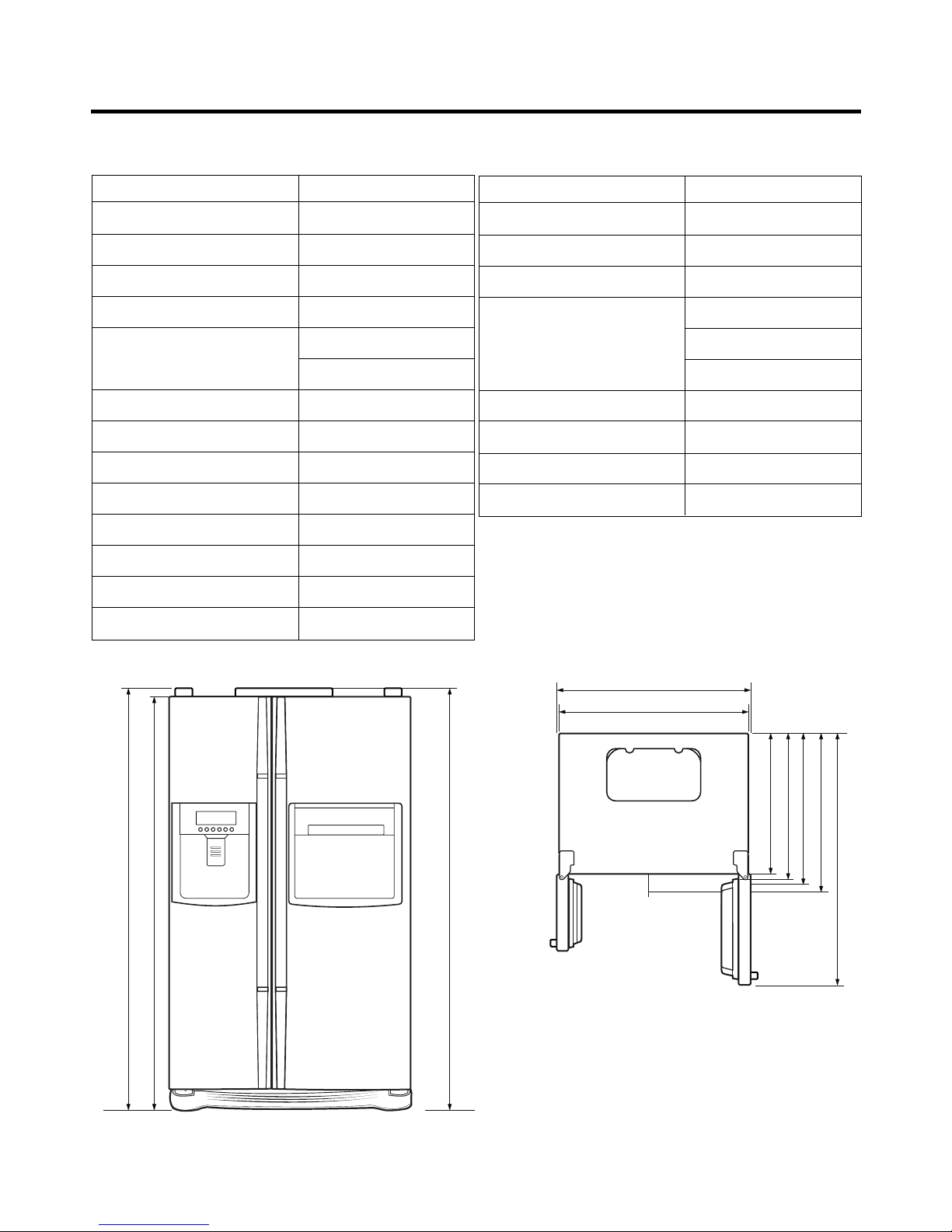
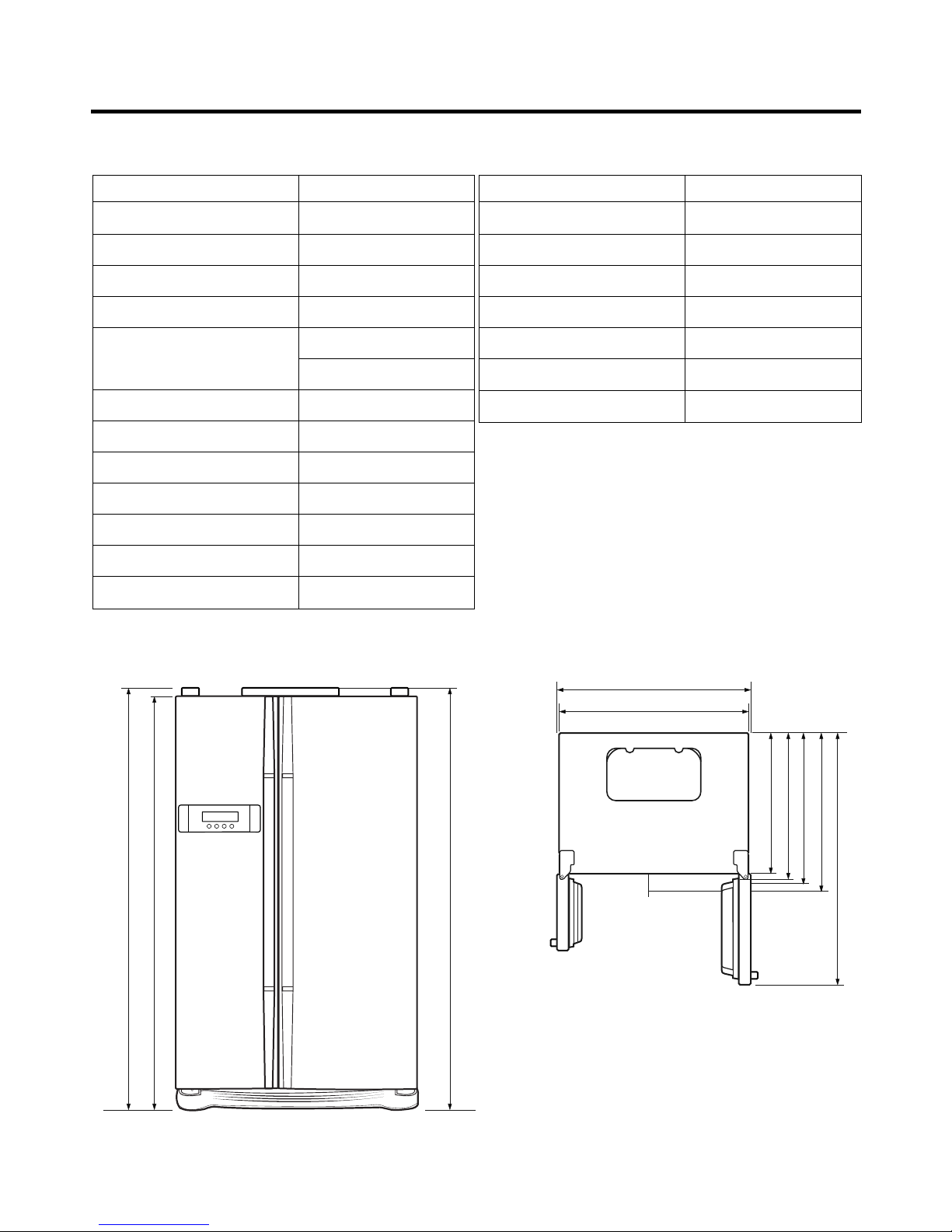
ITEMS SPECIFICATIONS
DIMENSIONS (mm) 890(W)X725(D)X1750(H)
NET WEIGHT (kg) 121
COOLING SYSTEM Fan Cooling
TEMPERATURE CONTROL Micom Control
DEFROSTING SYSTEM Full Automatic
Heater Defrost
INSULATION Cyclo-Pentane
COMPRESSOR P.T.C. Starting Type
EVAPORATOR Fin Tube Type
CONDENSER Wire Condenser
REFRIGERANT R134a (180g)
LUBRICATING OIL FREOL @10G (310 cc)
DRIER ID 0.83
CAPILLARY TUBE MOLECULAR SIEVE XH-7
1750
1720
1750
600
948
890
666
711
725
1133.5
<Front View> <Plane View>
1. Ref No. : GR-P207
ITEMS SPECIFICATIONS
FIRST DEFROST 4 - 5 Hours
DEFROST CYCLE 13 - 15 Hours
DEFROSTING DEVICE Heater, Sheath
ANTI SWEAT HEATER Dispenser Duct Door Heater
Dispenser Heater
Home Bar Heater
ANTI-FREEZING HEATER Damper Heater
FREEZER LAMP 40W (1 EA)
REFRIGERATOR LAMP 40W (1 EA)
DISPENSER LAMP 15W (1 EA)
SPECIFICATIONS
- 5 -
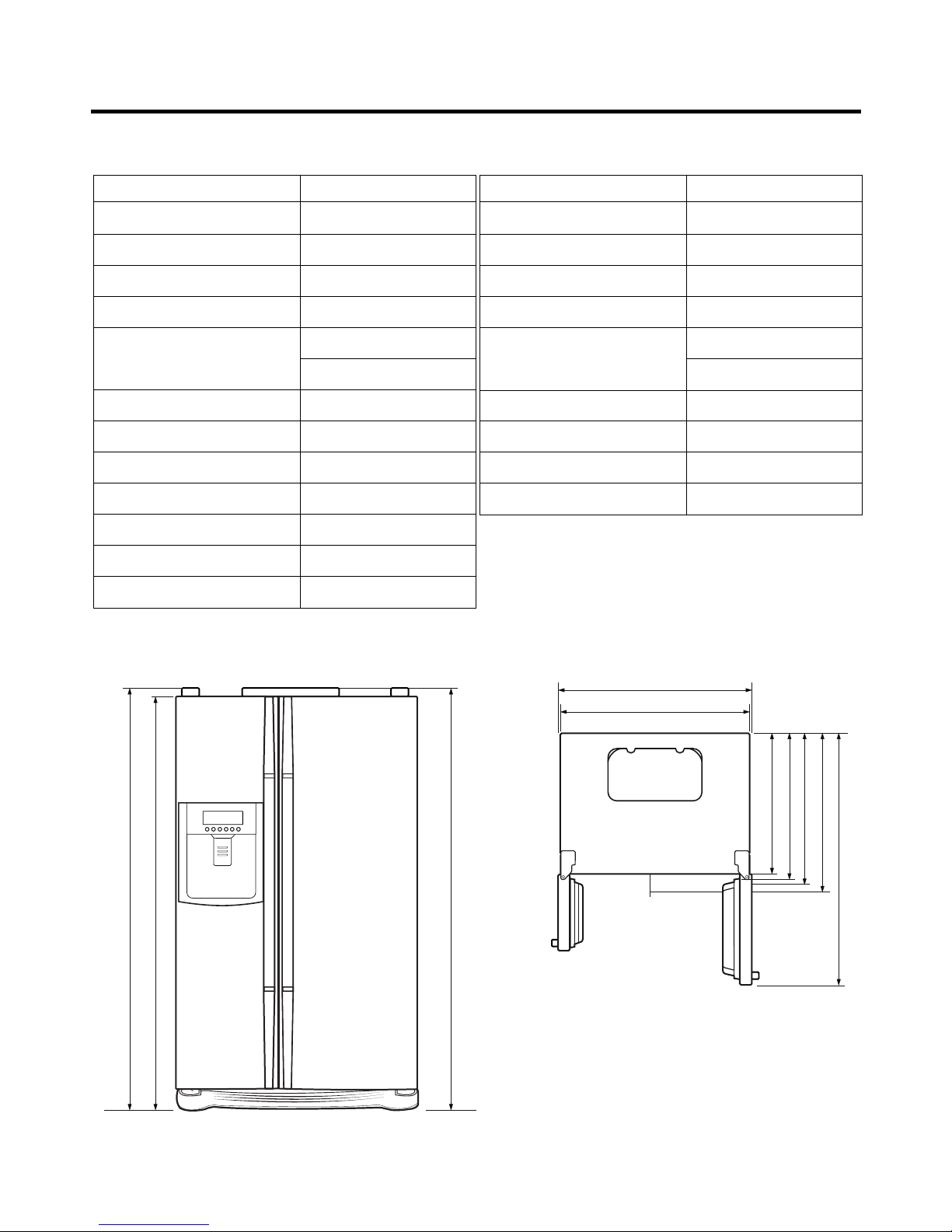
ITEMS SPECIFICATIONS
DIMENSIONS (mm) 890(W)X725(D)X1750(H)
NET WEIGHT (kg) 120
COOLING SYSTEM Fan Cooling
TEMPERATURE CONTROL Micom Control
DEFROSTING SYSTEM Full Automatic
Heater Defrost
INSULATION Cyclo-Pentane
COMPRESSOR P.T.C. Starting Type
EVAPORATOR Fin Tube Type
CONDENSER Wire Condenser
REFRIGERANT R134a (180g)
LUBRICATING OIL FREOL @10G (310 cc)
DRIER ID 0.83
ITEMS SPECIFICATIONS
CAPILLARY TUBE MOLECULAR SIEVE XH-7
FIRST DEFROST 4 - 5 Hours
DEFROST CYCLE 13 - 15 Hours
DEFROSTING DEVICE Heater, Sheath
ANTI SWEAT HEATER Dispenser Duct Door Heater
Dispenser Heater
ANTI-FREEZING HEATER Damper Heater
FREEZER LAMP 40W (1 EA)
REFRIGERATOR LAMP 40W (1 EA)
DISPENSER LAMP 15W (1 EA)
1750
1720
1750
600
948
890
666
711
725
1133.5
<Front View> <Plane View>
2. Ref No. : GR-L207
SPECIFICATIONS
- 6 -
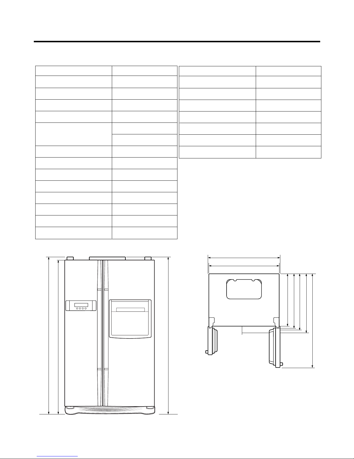
ITEMS SPECIFICATIONS
DIMENSIONS (mm) 890(W)X725(D)X1750(H)
NET WEIGHT (kg) 107
COOLING SYSTEM Fan Cooling
TEMPERATURE CONTROL Micom Control
DEFROSTING SYSTEM Full Automatic
Heater Defrost
INSULATION Cyclo-Pentane
COMPRESSOR P.T.C. Starting Type
EVAPORATOR Fin Tube Type
CONDENSER Wire Condenser
REFRIGERANT R134a (180g)
LUBRICATING OIL FREOL @10G (310 cc)
DRIER ID 0.83
CAPILLARY TUBE MOLECULAR SIEVE XH-7
1750
1720
1750
600
948
890
666
711
725
1133.5
<Front View> <Plane View>
3. Ref No. : GR-C207
ITEMS SPECIFICATIONS
FIRST DEFROST 4 - 5 Hours
DEFROST CYCLE 13 - 15 Hours
DEFROSTING DEVICE Heater, Sheath
ANTI SWEAT HEATER Home Bar Heater
ANTI-FREEZING HEATER Damper Heater
FREEZER LAMP 40W (1 EA)
REFRIGERATOR LAMP 40W (1 EA)
SPECIFICATIONS
- 7 -
ITEMS SPECIFICATIONS
DIMENSIONS (mm) 890(W)X725(D)X1750(H)
NET WEIGHT (kg) 106
COOLING SYSTEM Fan Cooling
TEMPERATURE CONTROL Micom Control
DEFROSTING SYSTEM Full Automatic
Heater Defrost
INSULATION Cyclo-Pentane
COMPRESSOR P.T.C. Starting Type
EVAPORATOR Fin Tube Type
CONDENSER Wire Condenser
REFRIGERANT R134a (180g)
LUBRICATING OIL FREOL @10G (310 cc)
DRIER ID 0.83
ITEMS SPECIFICATIONS
CAPILLARY TUBE MOLECULAR SIEVE XH-7
FIRST DEFROST 4 - 5 Hours
DEFROST CYCLE 13 - 15 Hours
DEFROSTING DEVICE Heater, Sheath
ANTI-FREEZING HEATER Damper Heater
FREEZER LAMP 40W (1 EA)
REFRIGERATOR LAMP 40W (1 EA)
1750
1720
1750
600
948
890
666
711
725
1133.5
<Front View> <Plane View>
4. Ref No. : GR-B207
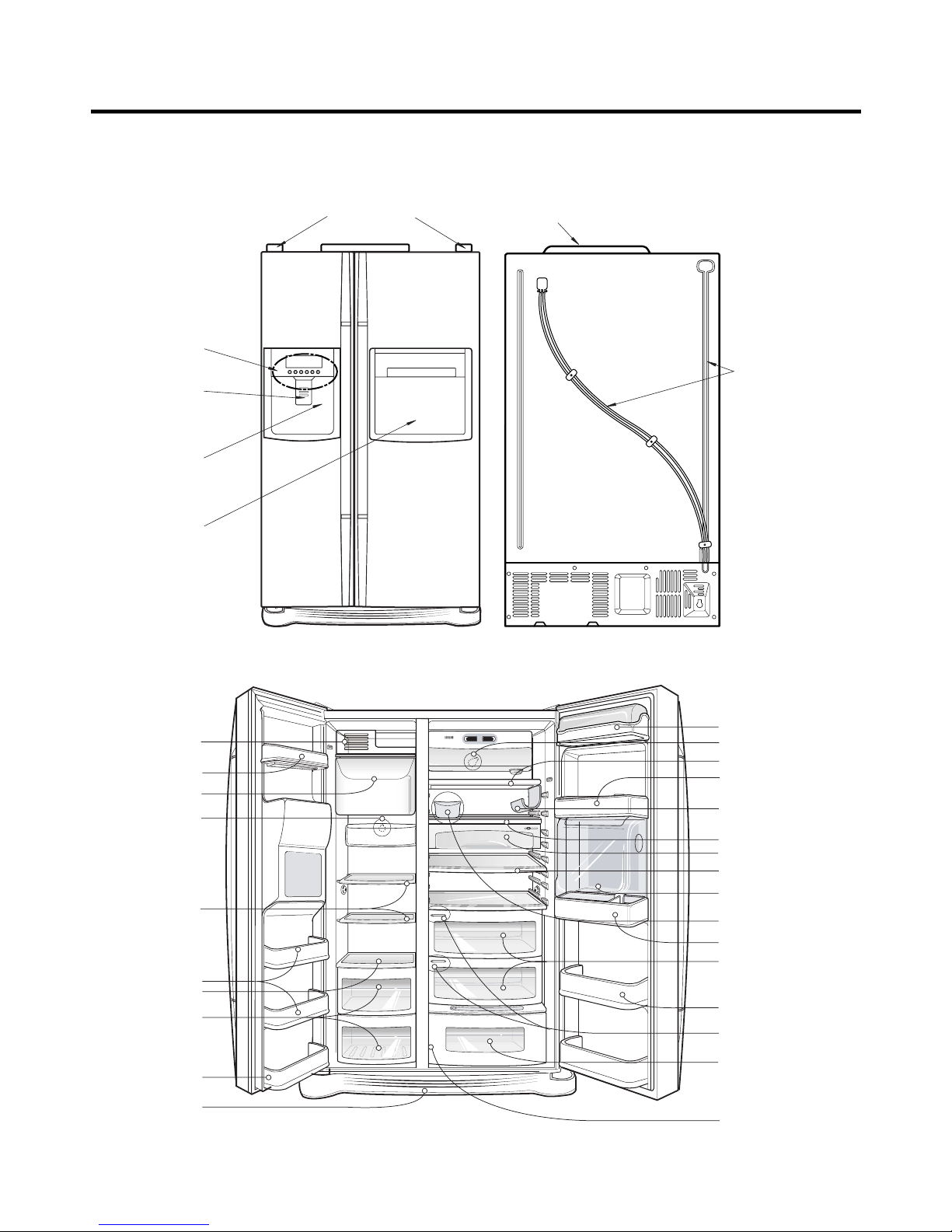
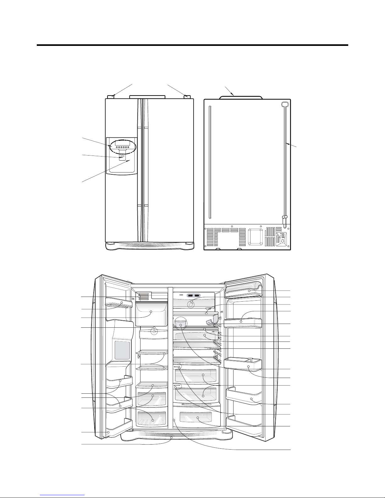
PARTS IDENTIFICATION
- 8 -
Cover Hinge
Home Bar
Frame Display
Cover PWB
Water Tube
Dispenser Lamp
Ice & Water
Dispenser Button
Freezer
compartment
Refrigerator
compartment
Milk product corner
Door rack
Space plus
Lamp
Automatic
ice maker
Shelf
(steel or glass)
Shelf
Door rack
Drawer
Door rack
Lower cover
Lamp
Shelf
Door rack
(1piece or 2piece)
Door rack
(1piece or 2piece)
Door rack
Shelf
Snack drawer (Optional)
Shelf(Folding or Normal)
*Refreshment center
(Optional)
Egg box
Vegetable drawer
(1 or 2)
*Miracle Zone (Optional)
Fresh compartment
(Optional)
*
Conversion switch
(Meats/Vegetables)
(Optional)
* Optional
Humidity switch
*Wine holder
(Plastic or wire)
1. Ref No. : GR-P207(Internal Filter)
2. Ref No. : GR-P207(External Filter)
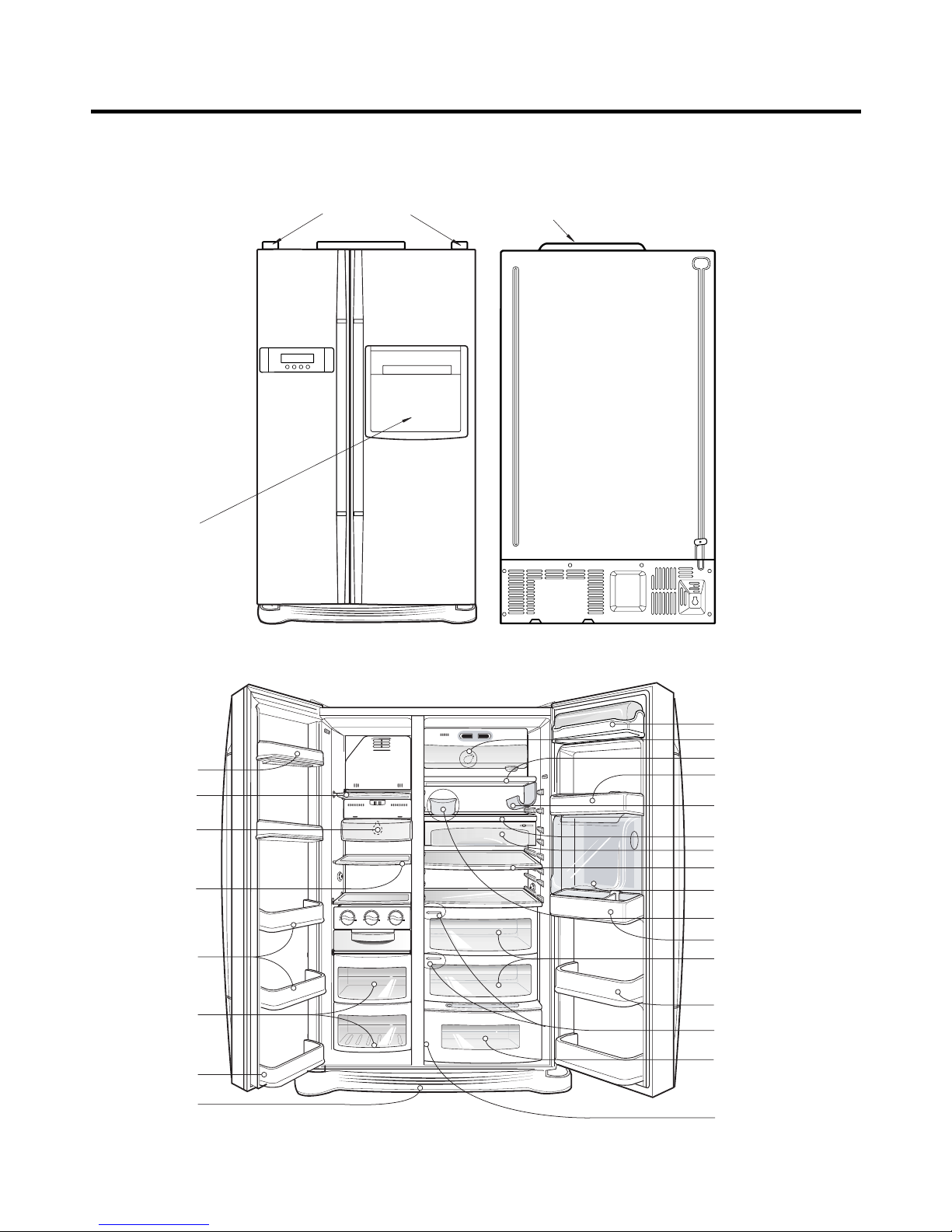
PARTS IDENTIFICATION
- 9 -
Freezer
compartment
Refrigerator
compartment
Milk product corner
Door rack
Space plus
Lamp
Automatic
ice maker
Shelf
(steel or glass)
Shelf
Door rack
Drawer
Door rack
Lower cover
Lamp
Shelf
Door rack
(1piece or 2piece)
Door rack
(1piece or 2piece)
Door rack
Shelf
Snack drawer (Optional)
Shelf(Folding or Normal)
*Refreshment center
(Optional)
Egg box
Vegetable drawer
(1 or 2)
*Miracle Zone (Optional)
Fresh compartment
(Optional)
*
Conversion switch
(Meats/Vegetables)
(Optional)
* Optional
Humidity switch
*Wine holder
(Plastic or wire)
Cover Hinge
Home Bar
Frame Display
Cover PWB
Water Tube
Dispenser Lamp
Ice & Water
Dispenser Button
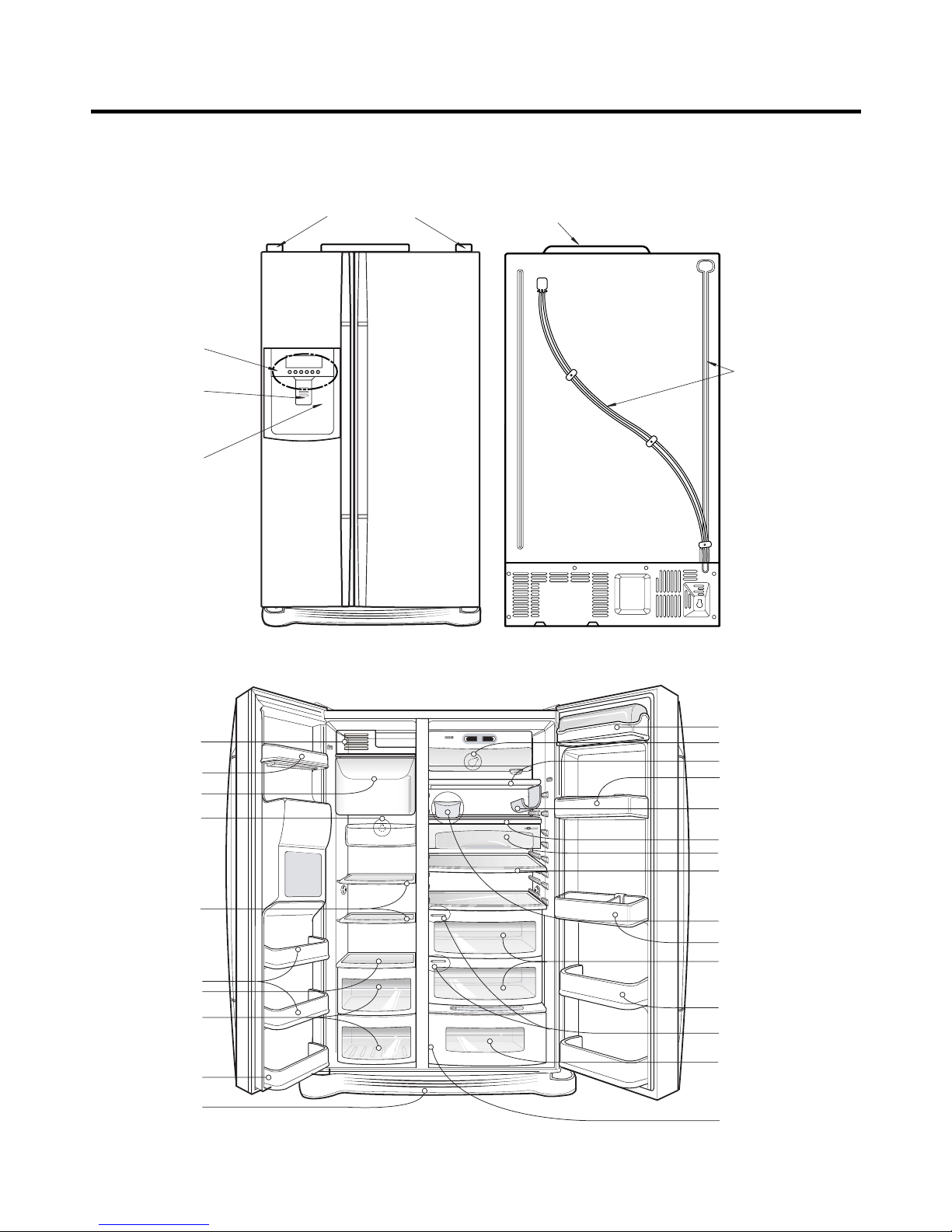
PARTS IDENTIFICATION
- 10 -
Freezer
compartment
Refrigerator
compartment
Milk product corner
Door rack
Space plus
Lamp
Automatic
ice maker
Shelf
(steel or glass)
Shelf
Door rack
Drawer
Door rack
Lower cover
Lamp
Shelf
Door rack
(1piece or 2piece)
Door rack
(1piece or 2piece)
Door rack
Shelf
Snack drawer (Optional)
Shelf(Folding or Normal)
Egg box
Vegetable drawer
(1 or 2)
*Miracle Zone (Optional)
Fresh compartment
(Optional)
*
Conversion switch
(Meats/Vegetables)
(Optional)
* Optional
Humidity switch
*Wine holder
(Plastic or wire)
Cover PWB
Water Tube
Cover Hinge
Frame Display
Dispenser Lamp
Ice & Water
Dispenser Button
3. Ref No. : GR-L207(Internal Filter)
4. Ref No. : GR-L207(External Filter)
PARTS IDENTIFICATION
- 11 -
Freezer
compartment
Refrigerator
compartment
Milk product corner
Door rack
Space plus
Lamp
Automatic
ice maker
Shelf
(steel or glass)
Shelf
Door rack
Drawer
Door rack
Lower cover
Lamp
Shelf
Door rack
(1piece or 2piece)
Door rack
(1piece or 2piece)
Door rack
Shelf
Snack drawer (Optional)
Shelf(Folding or Normal)
Egg box
Vegetable drawer
(1 or 2)
*Miracle Zone (Optional)
Fresh compartment
(Optional)
*
Conversion switch
(Meats/Vegetables)
(Optional)
* Optional
Humidity switch
*Wine holder
(Plastic or wire)
Cover PWB
Water Tube
Cover Hinge
Frame Display
Dispenser Lamp
Ice & Water
Dispenser Button
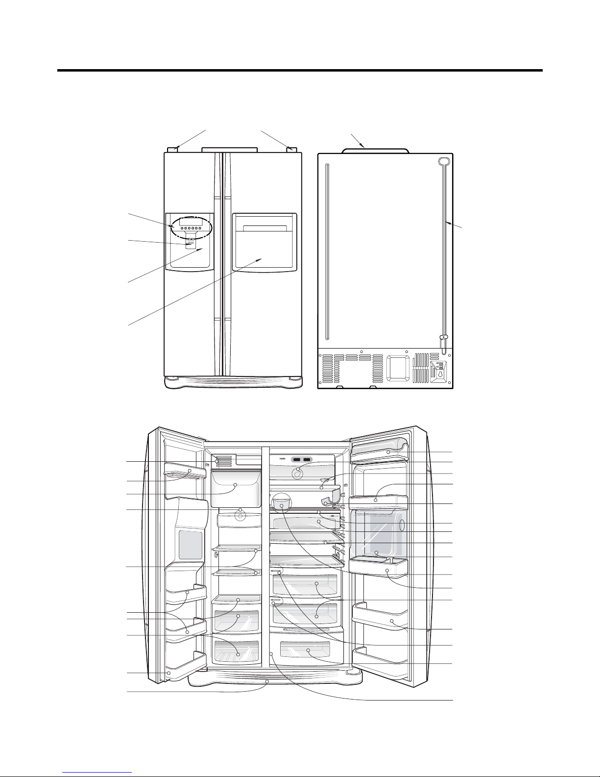
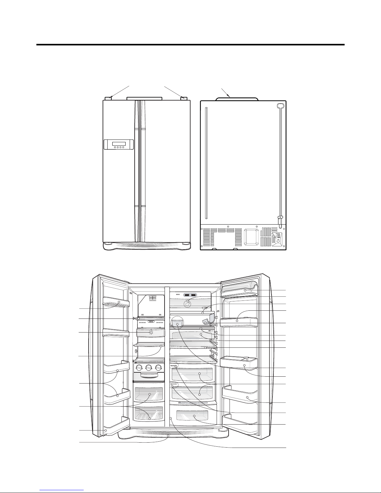
PARTS IDENTIFICATION
- 12 -
Freezer
compartment
Refrigerator
compartment
Door rack
Cover, Lamp-F
Shelf-F
Shelf-F
Door rack
Drawer
Door rack
Lower cover
compartment
Refrigerator
compartment
Milk product corner
Lamp
Shelf
Door rack
(1piece or 2piece)
Door rack
(1piece or 2piece)
Door rack
Shelf
Snack drawer (Optional)
Shelf(Folding or Normal)
Egg box
Vegetable drawer
(1 or 2)
*Miracle Zone (Optional)
Fresh compartment
(Optional)
*
Conversion switch
(Meats/Vegetables)
(Optional)
* Optional
Humidity switch
*Wine holder
(Plastic or wire)
*Refreshment center
(Optional)
Cover Hinge
Home Bar
Cover PWB
1. Ref No. : GR-C207
PARTS IDENTIFICATION
- 13 -
Freezer
compartment
Refrigerator
compartment
Door rack
Cover, Lamp-F
Shelf-F
Shelf-F
Door rack
Drawer
Door rack
Lower cover
compartment
Refrigerator
compartment
Milk product corner
Lamp
Shelf
Door rack
(1piece or 2piece)
Door rack
(1piece or 2piece)
Door rack
Shelf
Snack drawer (Optional)
Shelf(Folding or Normal)
Egg box
Vegetable drawer
(1 or 2)
*Miracle Zone (Optional)
Fresh compartment
(Optional)
*
Conversion switch
(Meats/Vegetables)
(Optional)
* Optional
Humidity switch
*Wine holder
(Plastic or wire)
Cover Hinge
Cover PWB
2. Ref No. : GR-B207
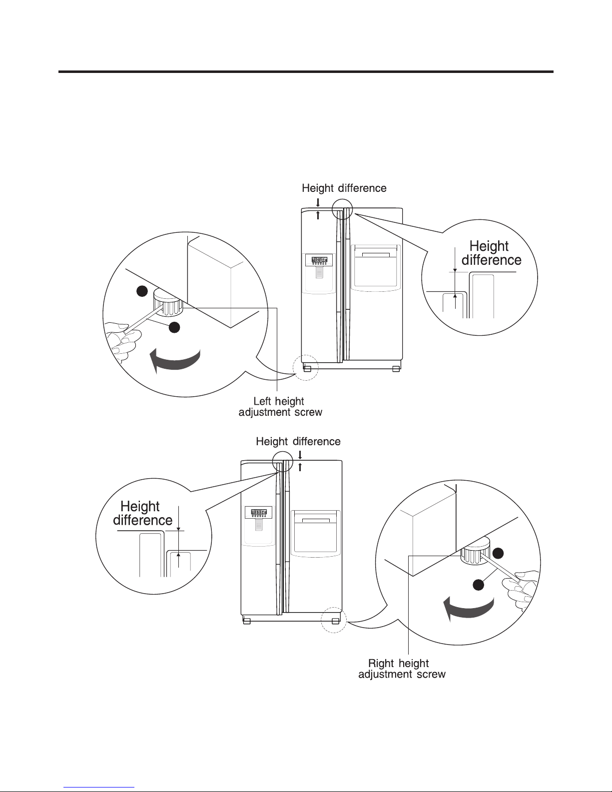
1. How to Adjust Door Height of Refrigerator
■ Make the refrigerator level first. (If the refrigerator is not installed on the flat floor, the height of freezer and refrigerator
door may not be the same.)
1. If the height of freezer door is lower than that of
refrigerator compartment :
2. If the height of freezer door is higher than that of
refrigerator compartment :
Insert a driver into the groove of adjusting screw
and rotate driver in arrow direction (clockwise) until the
refrigerator becomes horizontal.
Insert a driver into the groove of adjusting screw
and rotate driver in arrow direction (clockwise) until the
refrigerator becomes horizontal.
HOW TO INSTALL REFRIGERATOR
- 14 -
1
1
2
2
Adjusting
Adjusting
Driver
Driver
2. How to Install Water Pipe
■ Before Installation
1. The icemaker requires the water pressure of 1.5 -
8.5kgf/cm
2
. (It is acceptable if city water fills a cup of
180cc with water for 3 seconds)
2. Install booster pump where the city water pressure is
below 1.5kgf/cm
2
for normal operation of water and ice
dispenser.
3. The total length of water pipe shall be less than 12m. Do
not bend the pipe at right angle. If the length is more
than 12m, there will be troubles on water supply due to
water pressure drop.
4. Please install water pipe where there is no heat around.
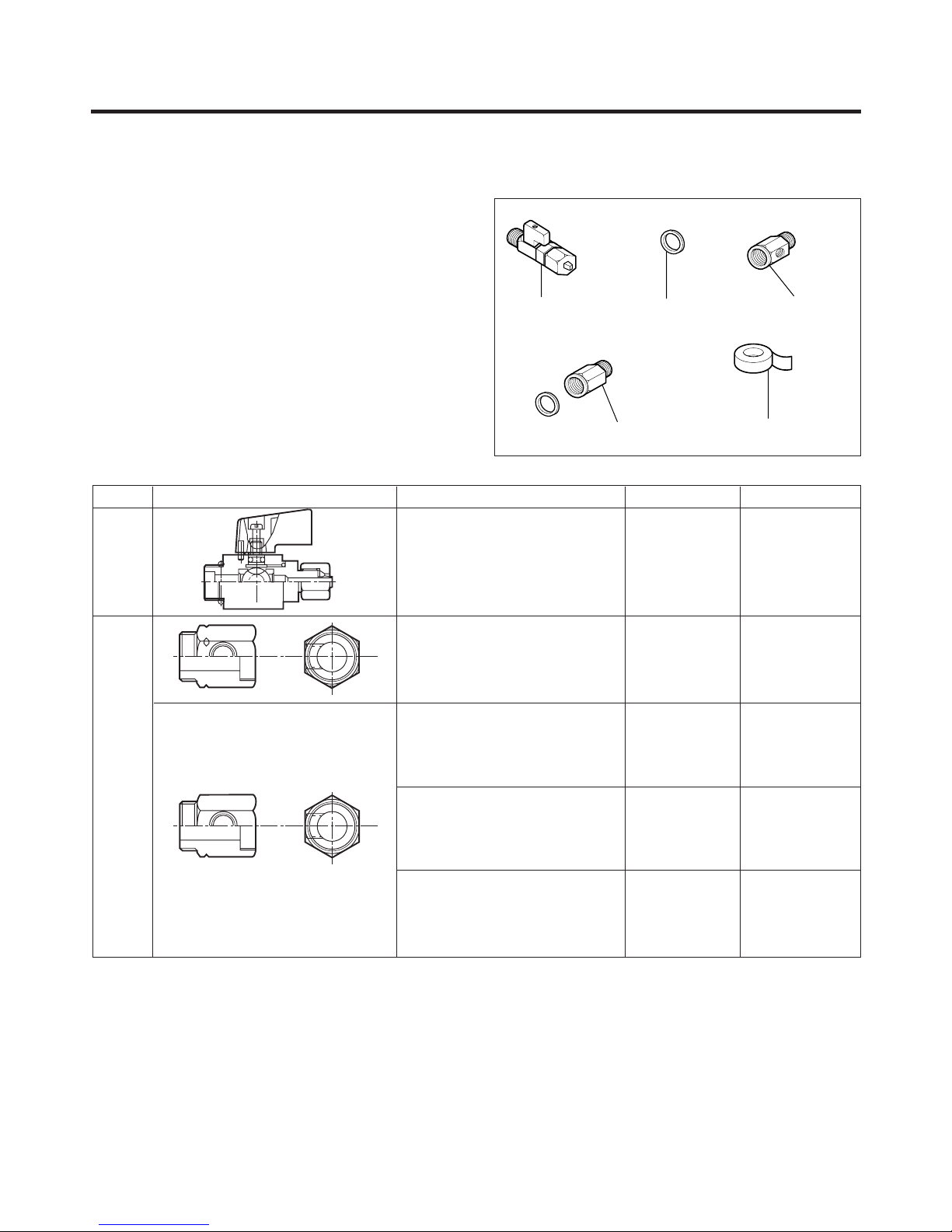
2-1. When connecting directly to the water tap.
■ Please confirm the following installation parts.
HOW TO INSTALL REFRIGERATOR
- 15 -
Class. Shape and Spec. Nomenclature P/No Remarks
Valve Feed 5221JA3001A Common Use
Connector, (MECH) Pipe 4932JA3003A
Conversion Connector(3/4") 6631JA3004A
No Holes
Balance Conector(3/4") 6631JA3004B
Packing(ø24x3t) 3920JA3001B
Connector, (MECH) Pipe 4932JA3003B
Conversion Connector(W25) 6631JA3004C
No Holes
Balance Conectoor(W25) 6631JA3004D
Packing(ø23x3t) 3920JA3001A
Connector, (MECH) Pipe 4932JA3003C
Conversion Connector(W28) 6631JA3004E
No Holes
Balance Conector(W28) 6631JA3004F
Packing(ø26x3t) 3920JA3001C
Connector, (MECH) Pipe 4932JA3003D
Conversion Connector(1/2") 6631JA3004G No Holes
Balance Conector(1/2") 6631JA3004H
Packing(ø19x3t) 3920JA3001D
Convertible
Water
Valve
Water
Connector
Valve Feed Rubber, Packing Connector, Pipe
Tape, TeflonConnector, Pipe
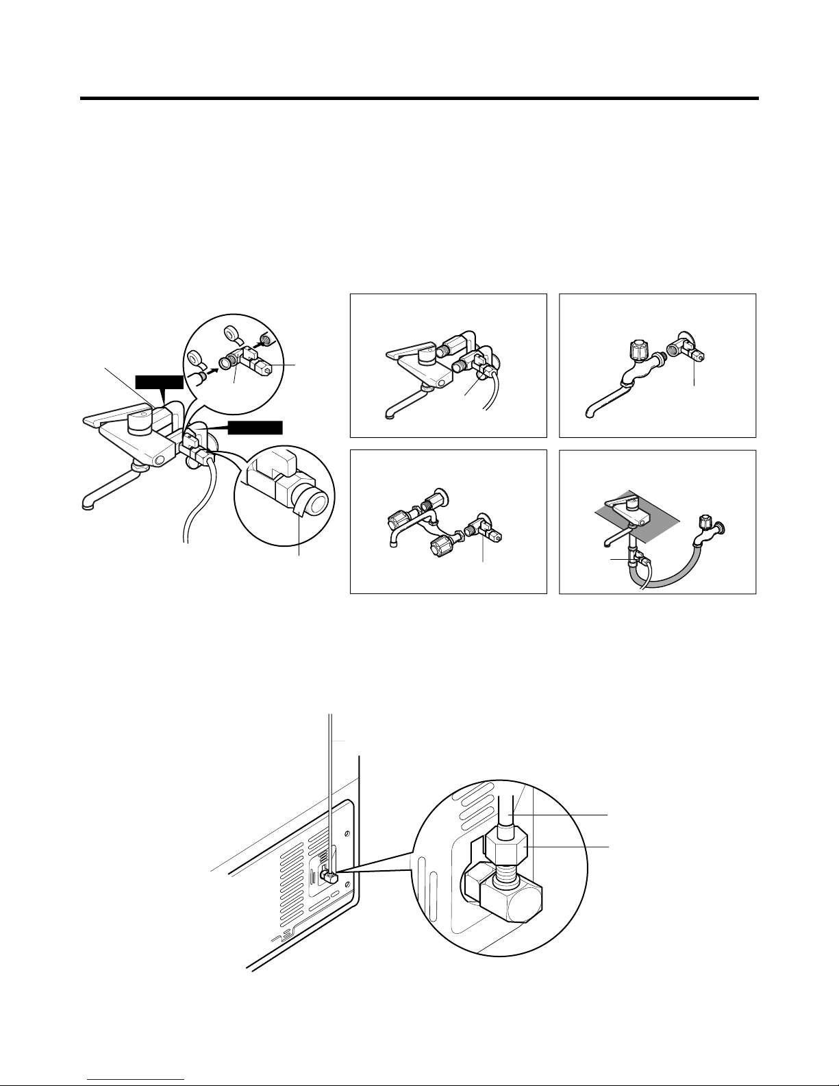
1. Connection of Pipe Connector A and B.
1) Turn off main valve of water pipe.
2) Disconnect water tap from piping by loosening nuts.
3) Connect pipe connector A and B to piping after sealing
the pipe connector with sealing tapes.
4) Connect feed valve to pipe connector A.
5) If there is only one tap water pipe, connect pipe
connector A only and install feed pipe.
2. Water Supply
1) After the installation of feed water, plug the refrigerator
to the earthered wall outlet, press the water dispenser
button for 2 - 3 minutes, and confirm that the water
comes out.
Caution : • Feed pipe should be connected to cold water
line. If it is connected to hot water line, trouble
may occur.
• Please check rubber packing when connecting
feed pipe.
2) Check leakage at connecting part, then arrange water
tube and locate the refrigerator at its regular place if
there is no leaking.
HOW TO INSTALL REFRIGERATOR
- 16 -
Single Lever Type Faucet
(general)
Feed
Valve
General Type
Feed
Valve
Two Hands Type Faucet Single Lever Type Faucet (one
hole, tech type and hand spray)
Feed
Valve
Feed
Valve
Pipe Connector B
Hot Water
Pipe Connector A
Feed
Valve
Cold Water
How to wind
Sealing Tapes.
Water Tube
Water Tube
Nut
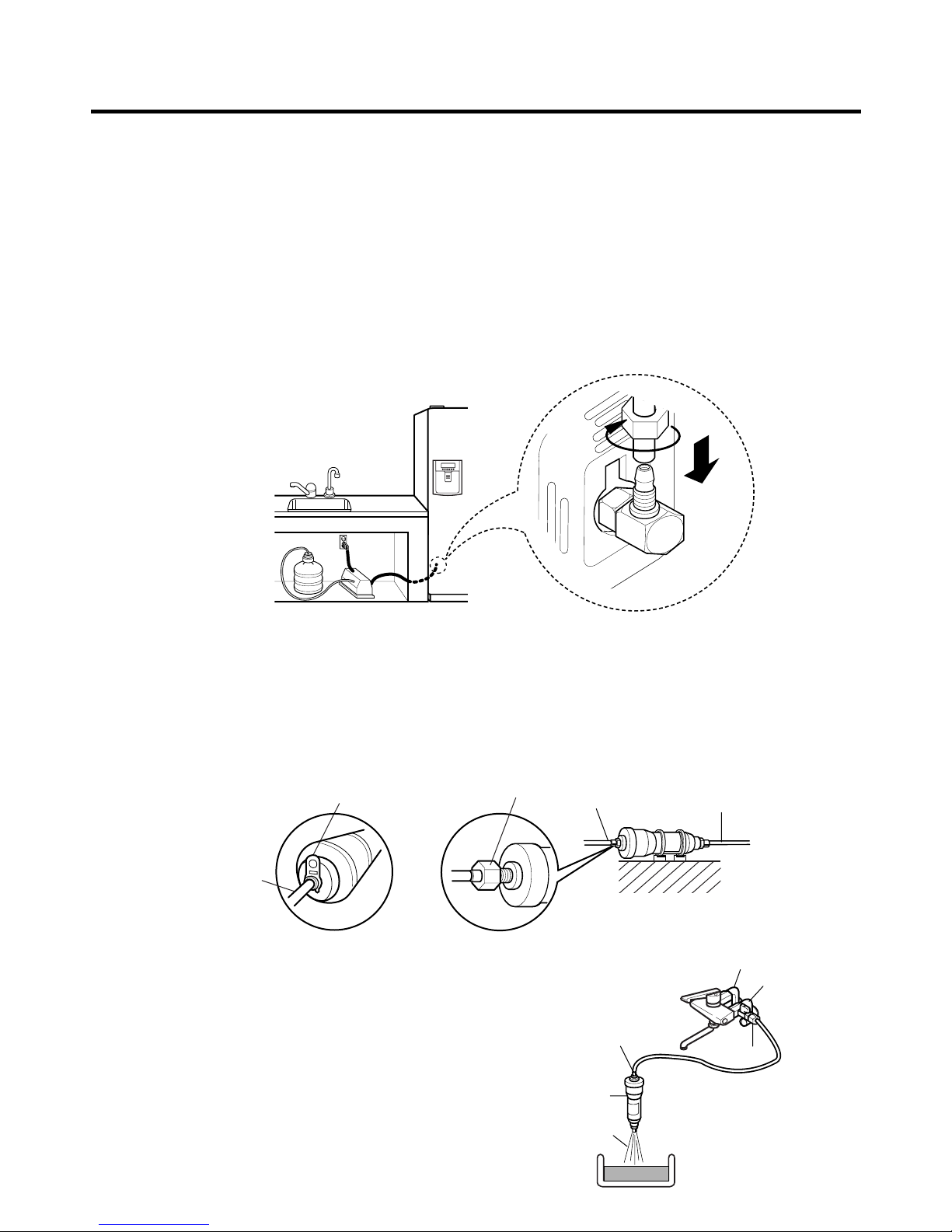
3. When customer uses bottled water.
*If customer wants to use bottled water, extra pump should be installed as shown below.
1. The pump system should not be on the floor (it may cause noise and vibration). Securely fasten the inlet and outlet
nuts of pump.
2. If there is any leakage after installation, cut the water tube at right angle and reassemble.
3. When put the water tube end into the bottle, leave a clearance between bottle bottom and water tube end.
4 Check water coming out and any leakage.
Caution : • If feed tube is more than 4m, less water will come out due to pressure drops.
• Use standard feed tube to prevent leaking.
■ Outternal Filter
1. Filter Fixation
1) There are two types of filter. One is nut type and the other is connector type.
2) Connect feed tube to the filter outlet and water valve connecting tube.
3) Fix the filter at proper place around the sink where it is easy to replace the filter and to receive the cleaning water.
Please consider the length of tube shall be less than 8m when locating filter.
2. Filter Cleaning
1) Connect feed tube to the inlet of feed valve and filter.
2) Clean the main valve and feed valve with water for at
least one minute until clean water comes out.
HOW TO INSTALL REFRIGERATOR
- 17 -
Water Tube
or
Nut
Nut
Inlet
Outlet
Connector Type Nut Type
Water
Filter
Filter Inlet
Feed Valve
Hot Water
Cold Water
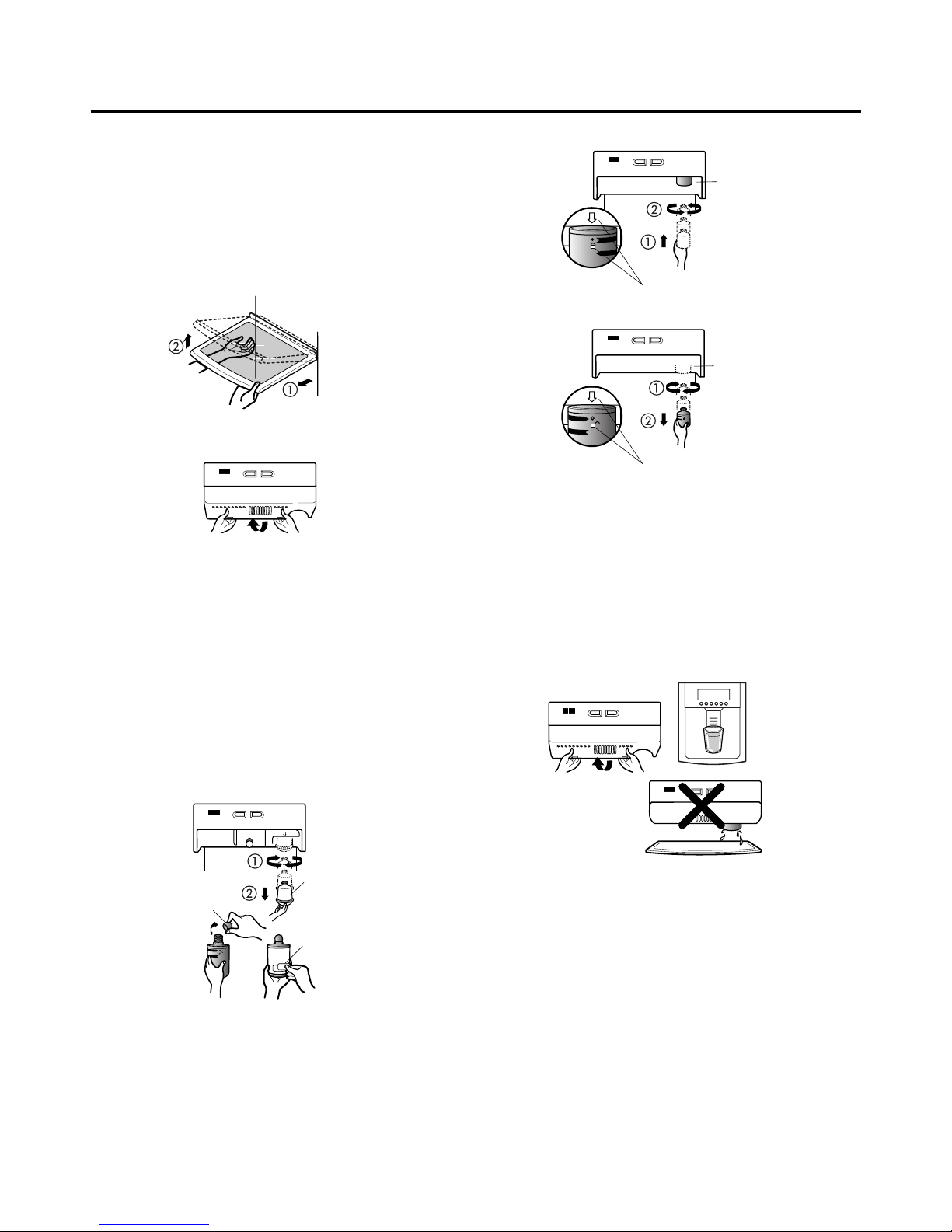
■ Install Water Filter (Applicable to some models only)
■ Before Installing water filter
1. Before installing the filter, take out the top shelf of the
refrigerator after tilting it to the direction () and lifting it
to the direction () and move it to the lower part.
2. Remove the lamp cover by pressing the protrusion
under the cover and pulling the cover to the front.
■ Installing water filter
1. Initial installation of water filter
Remove the filter substitute cap by turning it
counterclockwise () by 90 degrees and pulling it down.
Note : Keep it safe to use it later when you do not use the
filter.
Remove the red cap from the filter and attach the
sticker. Insert the upper part of the filter () after
aligning with the guideline marked on the control box,
and fasten it by turning it clockwise by 90 degrees.
Note : Check that the guideline and the fastening
indication line are aligned.
2. Replacement of water filter
While holding the lower part of the filter, turn it
counterclockwise () by 90 degrees and pull it down.
Note : Check that the guideline and the loosening
indication line are aligned.
■ After installing water filter
Reassemble the lamp cover and the top shelf of the
refrigerator. To place the top shelf of the refrigerator, raise
the front part of the shelf a bit so that the hook of the shelf
is fit into the groove.
In order to clean the water filter system, drain water for
about 3 min.
Note : Then open the door of the refrigerator and check for
water droppings on the shelf under the filter.
Control box
Aligning with the guide line
and the fastening indication line
Aligning with the guide line
and the loosening indication line
Control box
Separation
of red cap
Adhesion
sticker
Substitute
cap
HOW TO INSTALL REFRIGERATOR
- 18 -
3. How to Control the Amount of Water Supplied to Icemaker.
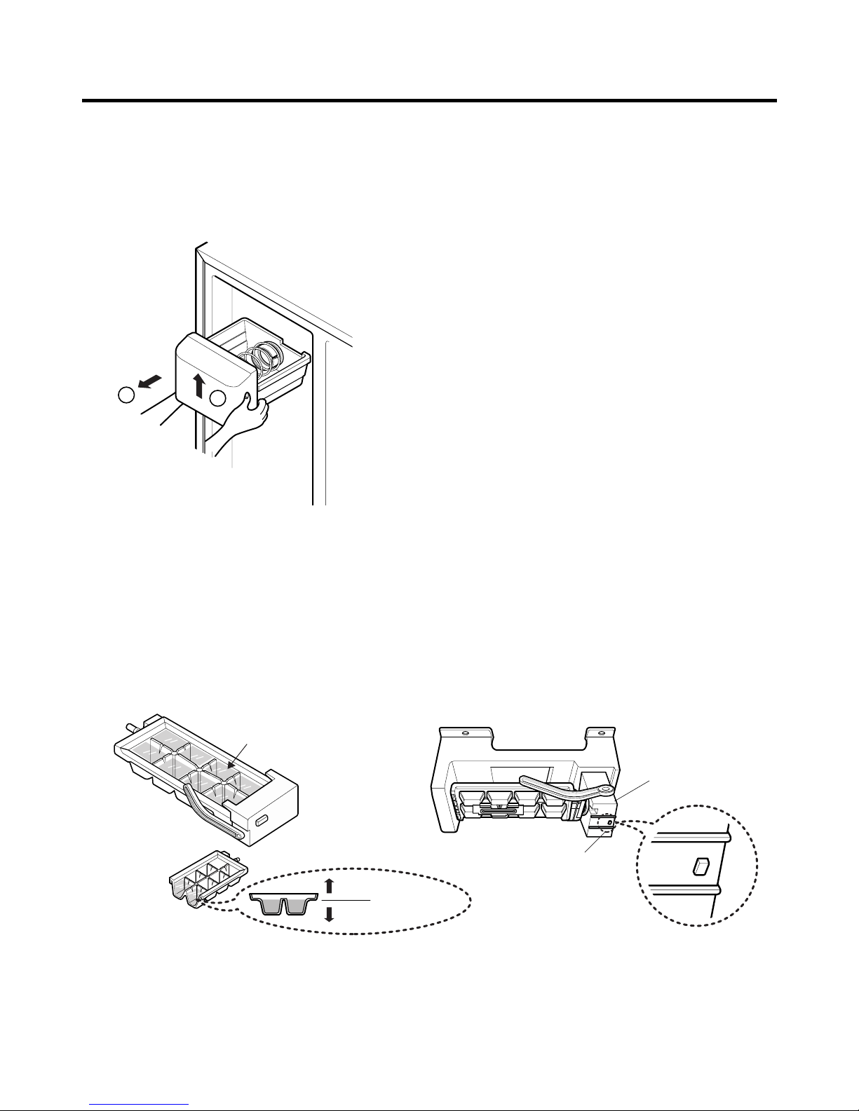
3-1. Confirm the amount of water supplied to the icemaker.
1. Lift and pull out the space plus in the upper part of the freezer compartment.
2. Pull out the ice bank in the upper part of the freezer compartment.
Caution : • Do not put hands or tools into the chute to confirm
the operation of geared motor.
it may damage refrigerator or hurt hands.)
• Check the operation of motor with its operation
noise.
2. Apply electricity after connecting water pipe.
1) Press test switch under the icemaker for two seconds as shown below.
2) The bell rings(ding~dong) and ice tray rotates and water comes out from the icemaker water tube.
3) The water shall be supplied two or three times into the tray. The amount of water supplied for each time is small.
Put a water container under the ice tray and press test switch.
4) When ice tray rotates, the water in it will spill. Collect the spilt water and throw away into the sink.
5) When ice tray has finished rotation, water comes out from the water tube. Confirm the amounts of water in the ice tray.
(refer to fig. The optimum amount of water is 110cc)
* It is acceptable if the adjusted level of water is a bit smaller than optimum level.
HOW TO INSTALL REFRIGERATOR
- 19 -
2
1
Test Switch
Confirm the amount
of water
Ice maker
Too much
Too little
Optimum level
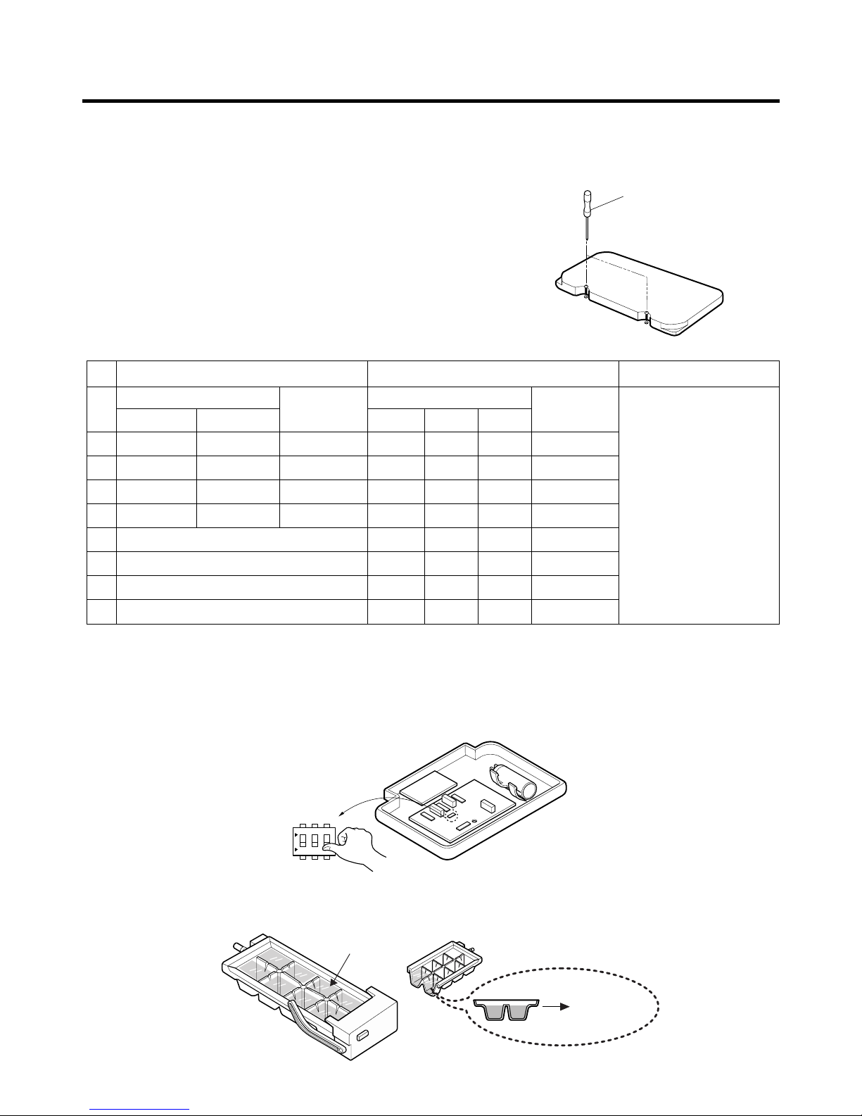
3-2. Control the amount of water supplied to the icemaker.
Caution : • Please unplug the power cord from the wall outlet and wait for more than three minutes before disconnecting
PWB cover as 310V is applied in the control panel.
1. Disconnect PWB cover from the upper part of the refrigerator.
2. Adjust the amount of water supplied by using DIP switch.
■ Water Supplying Time Control Option
1) The water supplying time is set at five seconds when the refrigerator is delivered.
2) The amount of water supplied depends on the setting time and water pressure (city water pressure).
3) If ice cube is too small, increase the water supplying time. This happens when too small water is supplied into the ice tray.
4) If ice cube sticks together, decrease the water supplying time. This happens when too much water is supplied into the ice tray.
Caution : When adjusting the amount of water supplied, adjust step by step. Otherwise the water may spill over.
3. When adjustment of control switch for the amount of water supplied is complete, check the level of water in the ice tray.
HOW TO INSTALL REFRIGERATOR
- 20 -
(+) Driver
1
ON
Switch ON
Switch OFF
23
Confirm the amount
of water
Optimum level
* The quantity of water
supplied depends on DIP
switch setting conditions
and water pressure as it
is a direct tap water
connection type. (the
water supplied is
generally 80 cc to 120 cc)
* DIP switch is on the main
PWB.
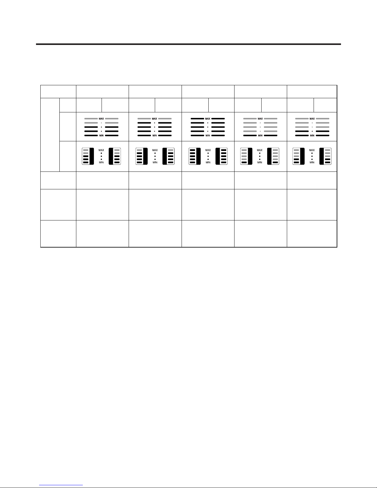
TYPE-3(Dot-LED) TYPE-2(Bar-LED) TYPE-1(88-LED)
No
DIP SWITCH SETTING
S1 S2
DIP SWITCH SETTING
S1 S2 S3
1
2
3
4
5
6
7
8
OFF OFF 6.5 SEC
ON OFF 5.5 SEC
OFF ON 7.5 SEC
ON ON 8.5 SEC
OFF OFF OFF 6.5 SEC
ON OFF OFF 5.5 SEC
OFF ON OFF 6 SEC
ON ON OFF 7 SEC
OFF OFF ON 7.5 SEC
ON OFF ON 8 SEC
OFF ON ON 9 SEC
ON ON ON 10 SEC
WATER
SUPPLY TIME
WATER
SUPPLY TIME
REMARKS
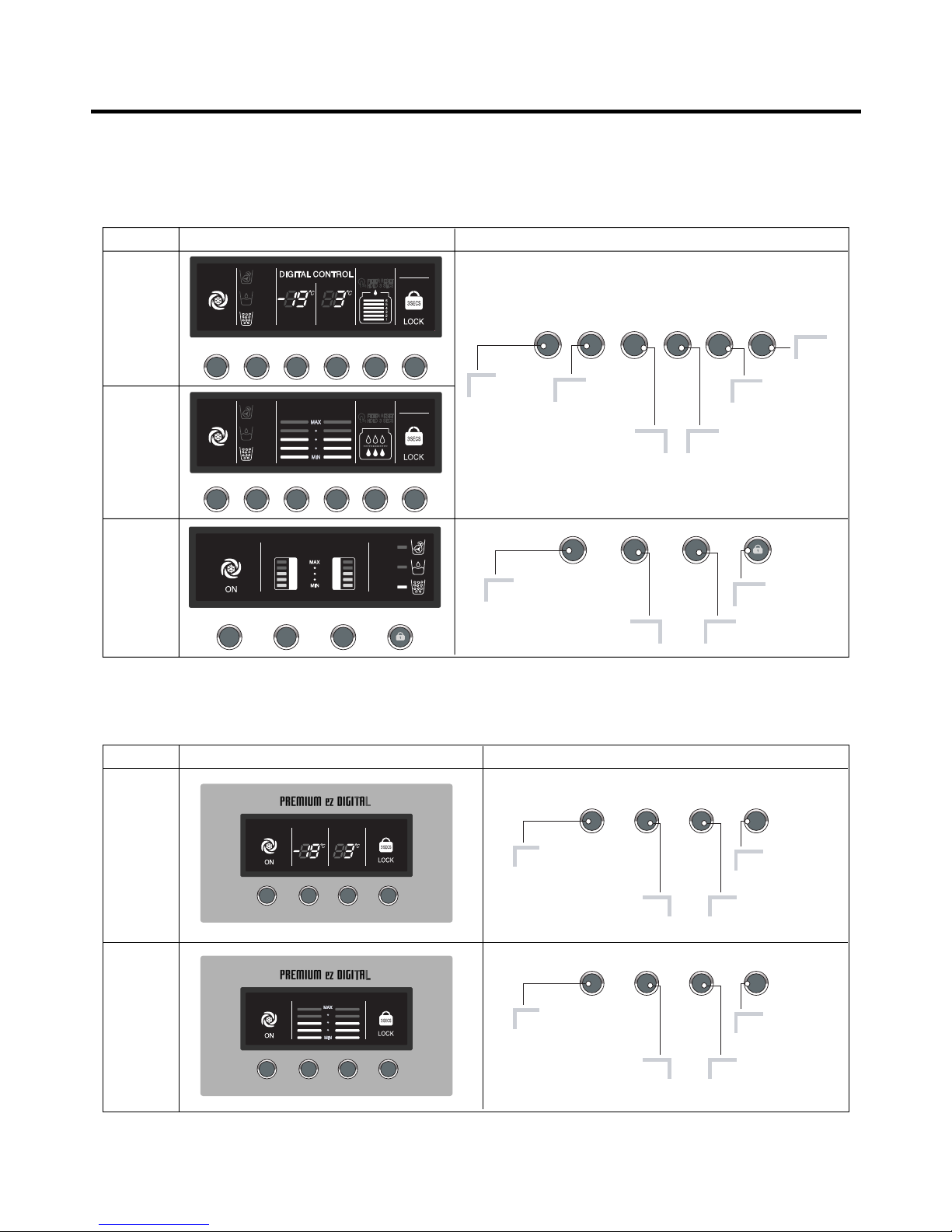
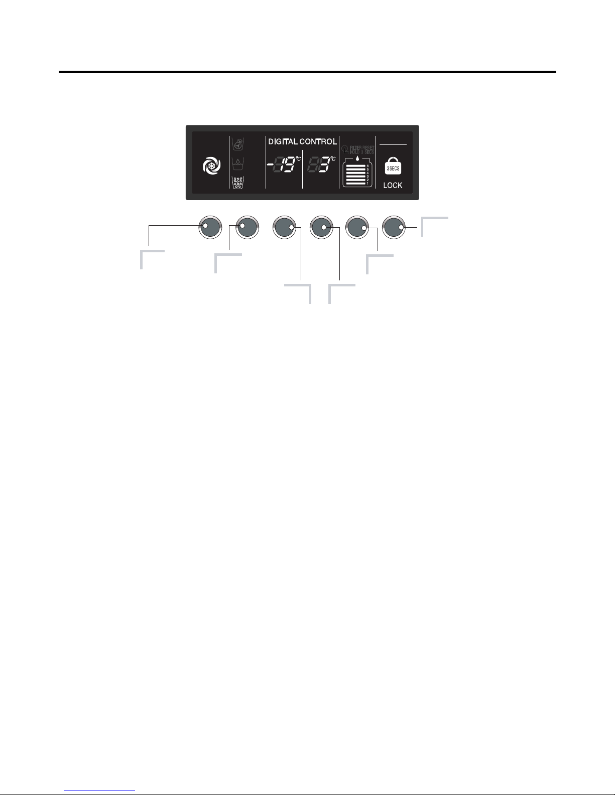
1. Monitor Panel
1-1. GR-P207, GR-L207
1-2. GR-C207, B207
MICOM FUNCTION
- 21 -
Optional Function display board Description
Type-1
(88-LED)
Type-2
(Bar-LED)
Type-3
(Dot-LED)
Type-1
(88-LED)
Type-2
(Bar-LED)
Optional Function display board Description
EXPRESS FRZ DISPENSER FREEZER REFRIGERATOR FILTER LOCK
DISPENSER
Lock: Hold 3 Secs
EXPRESS FRZ FREEZER REFRIGERATOR
CUBE
WATER
CRUSH
FRZ TEMP REF TEMP
EXPRESS FRZ
Express freezer.
Dispenser
selection button.
Lock button.
Filter reset button.
Temperature adjustment button
for refrigerator compartment.
Temperature adjustment button
for freezer compartment.
EXPRESS FRZ DISPENSER FREEZER REFRIGERATOR FILTER LOCK
Express freezer.
Dispenser
selection button.
Temperature adjustment button
for refrigerator compartment.
Temperature adjustment button
for freezer compartment.
EXPRESS FRZ DISPENSER
Lock: Hold 3 Secs
FREEZER REFRIGERATOR
Express freezer.
Lock button.
Temperature adjustment button
for refrigerator compartment.
Temperature adjustment button
for freezer compartment.
EXPRESS FRZ LOCKFREEZER REFRIGERATOR
Express freezer.
Lock button.
Temperature adjustment button
for refrigerator compartment.
Temperature adjustment button
for freezer compartment.
EXPRESS FRZ LOCKFREEZER REFRIGERATOR
EXPRESS FRZ
CHILD LOCK
LOCKEXPRESS FRZ FREEZER REFRIGERATOR
FRZ TEMP REF TEMP
EXPRESS FRZ
CHILD LOCK
LOCKEXPRESS FRZ FREEZER REFRIGERATOR
FRZ TEMP REF TEMP
FRZ TEMP REF TEMP
FILTER STATUS DISPENSER
BUTTON
EXPRESS
FRZ
ON
CUBE
WATER
CRUSH
EXPRESS FRZ DISPENSER FREEZER REFRIGERATOR FILTER LOCK
EXPRESS
FRZ
CUBE
WATER
CRUSH FRZ TEMP REF TEMP
FILTER STATUS DISPENSER
BUTTON
ON
1-3. Display Second Function
1. Buzzer sound mute Mode
The buzzer sound is set to OFF.
It activates by sounding the recognition sound of “Ding~” after pressing and holding “Express FRZ” button more than 5
seconds. It inactivates when resetting the mode power.
2. Display Power saving Mode
It places display in standby mode until door is opened.
Press “Freezer” and “Express FRZ” buttons simultaneously to turn all leds become ON and then OFF with the recognition
sound of “Ding~” after 5 seconds. (Be sure not to press only one button to work.)
Once the mode activates, the display is always OFF. Until door is opened or display button is pressed. When 30 seconds
has elapsed after closing door or pressing button, the display turns OFF. To deactivate this mode is same as the
activation methods. The mode inactivates when resetting the power.
3. Exhibition Mode
This function is available when exhibiting a refrigerator in the shopping moll.
Function is inserted with recognition sound “Ding ~” if pressing both the “Express FRZ” button and the “REFRIGERATOR”
button at the same time for more than 5 seconds. If function is inserted, all basic refreezing functions at the R/F room and
the Storage room (COMP, F-FAN, C-FAN) turns off and the display normally operates. However, the dispenser function
normally operates.
The DEMO stops if pressing the button during DISPLAY DEMO, DEMO stops and the display normally operates but
performs DEMO operation again if not pressing the button again for more than 30 seconds (DEMO: Display scenario
when using the display).
Release method is same as input method.
The mode is released if power is reset.
MICOM FUNCTION
- 22 -
EXPRESS FRZ DISPENSER FREEZER REFRIGERATOR FILTER LOCK
EXPRESS
FRZ
CUBE
WATER
CRUSH FRZ TEMP REF TEMP
FILTER STATUS DISPENSER
BUTTON
ON
Express freezer.
Dispenser
selection button.
Lock button.
Filter reset button.
Temperature adjustment button
for refrigerator compartment.
Temperature adjustment button
for freezer compartment.
2. Description of Function
2-1. Funnction of Temperature Selection
* The temperature can vary ±3 °C depending on the load condition. *( ) : 127V/60Hz, 110~115V/60Hz, 115V/60Hz Rating ONLY.
*< > : TAIBEI
1. When power is initially applied or reapplied after power cut, “Medium” is automatically selected.
2. When the temperature selection switch in the freezer and refrigerator compartments is pressed, the light is on in the
following sequence:
"Middle" ➝ "Middle Strong" ➝ "Strong" ➝ "Weak" ➝ "Middle Weak"
3. The temperature setting condition of freezer and refrigerator compartments shall not be indicate in the standard model
(GR-P207, GR-L207, GR-C207, GR-B207) when refrigerator or home bar door is closed.
MICOM FUNCTION
- 23 -
Division Power Initially On 1st Press 2nd Press 3th Press 4th Press
Type-1
(88-LED)
Type-2
(Bar-LED)
Type-3
(Dot-LED)
-
19 °C 3 °C
-
22°C 2 °C
-
23 °C 0 °C
-
15 °C 6 °C
-
17 °C 4 °C
Change
of
Indication
Lamp
Temperature
Control
Middle Middle Strong Strong Weak Middle Weak
-19 °C
(-18 °C)
<-19 °C>
3 °C
<2 °C>
1.5 °C
<1 °C>
0 °C
<0 °C>
6 °C
<4.5 °C>
4.5 °C
<3 °C>
-21 °C
(-21 °C)
<-21 °C>
-23 °C
(-22 °C)
<-22 °C>
-15 °C
<-16.5 °C>
-17 °C
<-18 °C>
Freezer
Control
Refrigeration
Control

2-2. Automatic ice maker
• The automatic ice maker can automatically make 8 pieces of ice cube at a time, 80 pieces a day. But these quantities may
be varied according to various conditions including how many times the refrigerator door opens and closes.
• Ice making stops when the ice storage bin is full.
• If you don’t want to use automatic ice-maker, change the ice-maker switch to ON-OFF.
If you want to use automatic ice-maker again, change the switch to OFF-ON.
NOTE : It is normal that a noise is produced when ice made is dropped into the ice storage bin.
2-3. When ice maker does not operate smoothly
Ice is lumped together
• When ice is lumped together, take the ice lumps out of the ice storage bin, break them into small pieces, and then place
them into the ice storage bin again.
• When the ice maker produces too small or lumped together ice, the amount of water supplied to the ice maker need to
adjusted. Contact the service center.
✻ If ice is not used frequently, it may lump together.
Power failure
• Ice may drop into the freezer compartment. Take the ice storage bin out and discard all the ice then dry it and place it
back. After the machine is powered again, crushed ice will be automatically selected.
The unit is newly installed
• It takes about 12 hours for a newly installed refrigerator to make ice in the freezer compartment.
2-4. Express freezing
1. Express freezing is function to improve cooling speed of the freezing room by consecutively operating compressors and
freezing room fan.
2. Express freezing is released if power failure occurs and then returns to the original status.
3. Temperature setting is not changed even if selecting the express freezing.
4. The change of temperature setting at the freezing room or the cold storage room is allowed with express freezing
selected and prrocessed.
5. The cold storage room operates the status currently set with Express freezing selected and procesed.
6. If selecting the Express freezing, the Express freezing function is released after continuously operating compressor and
freezing room fan.
7. If frost removal starting time is arrived during Express freezing, Express freezing operation is done only for the remaining
time after completion of frost removal when the Express freezing operation time passes 90 minutes. If passing 90
minutes, Express freezing operation is done only for 2 hours after completion of frost removal.
8. If pressing Express freezing button during frost removal, the Express freezing LED is turned on but if pressing the
Express freezing, compressor operates after the remaining time has passed.
9. If selection Express freezing within 7 minutes (delay for 7 minutes of compressor) after the compressor stops,
compressor operates after the remaining time has passed.
10. The freezing room fan motor operates at the high speed of RPM during operation of Express freezing.
MICOM FUNCTION
- 24 -
2-5. Control of variable type of freezing room fan
1. To increase cooling speed and load response speed, MICOM variably controls freezing room fan motor at the high speed
of RPM and standard RPM.
2. MICOM only operates in the input of initial power or special freezing operation or load response operation for the high
speed of RPM and operates in the standard RPM in other general operation.
3. If opening doors of freezing / cold storage room or home bar while fan motor in the freezing room operates, the freezing
room fan motor normally operates (If being operated in the high speed of RPM, it converts operation to the standard
RPM). However, if opening doors of freezing room or home bar, the freezing room fan motor stops.
4. As for monitoring of BLDC fan motor error in the freezing room, MICOM immediately stops the fan motor by determining
that the BLDC fan motor is locked or poor if there would be position signal for more than 65 seconds at the BLDC motor.
Then it displays failure (refer to failure diagnosis function table) at the display part of refrigerator, performs re-operation in
the cycle of 30 minutes. If normal operation is performed, poor status is released and refrigerator returns to the initial
status (reset).
2-6. Control of M/C room fan motor
1. The M/C room fan motor performs ON/OFF control by linking with the COMP.
2. It controls at the single RPM without varying RPM.
3. Failure sensing method is same as in fan motor of freezing fan motor (refer to failure diagnosis function table for failure
display).
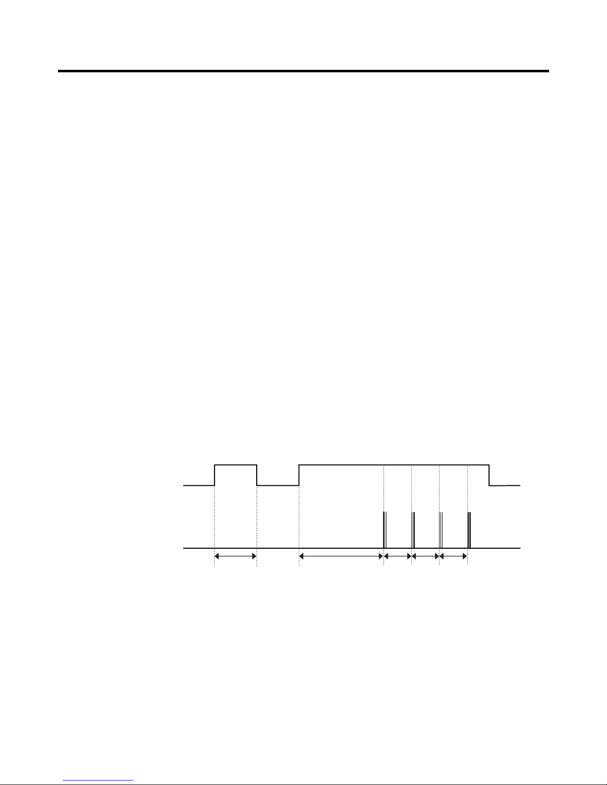
2-7. Door opening alarm
1. Buzzer generates alarm sound if doors are not closed even when more than a minute consecutively has passed with
doors of freezing / cold storage room or home bar opened.
2. Buzzer rings three times in the interval of 0.5 second after the first one-minute has passed after doors are opened and
then repeats three times of On/Off alarm in the cycle of every 30 seconds.
3. If all the doors of freezing / cold storage room or home bar are closed during door open alarm, alarm is immediately
released.
2-8. Ringing of button selection buzzer
1. If pressing the front display button, “Ding ~ “ sound rings.
2-9. Ringing of compulsory operation, compulsory frost removal buzzer
1. If pressing the test button in the main PCB, “Phi ~ “ sound rings.
2. In selecting compulsory operation, alarm sound is repeated and completed in the cycle of On for 0.2 second and Off for
1.8 second three times.
3. In selecting compulsory frost removal, alarm sound is repeated and completed in the cycle of On for 0.2 second , Off for
0.2 second, On for 0.2 second and Off for 1.4 second three times.
MICOM FUNCTION
- 25 -
Doors of freezing /
cold storage room
or home bar
BUZZER
Closing
Opening
Within
a minute
A minute
30
seconds30seconds30seconds
Opening
Closing Closing
3 Times 3 Times 3 Times 3 Times
2-10. Frost removal function
1. Frost removal is performed whenever total operation time of compressor becomes 7 ~ 7.5 hour.
2. In providing initial power (or returning power failure), frost removal starts whenever total operation time of compressor
becomes 4 ~ 4.5 hour.
3. Frost removal is completed if temperature of a frost removal sensor becomes more than 5°C after starting frost removal.
Poor frost removal is not displaced if it does not arrive at 5°C even if two hours have passed after starting frost removal.
4. No removal is done if frost removal sensor becomes poor (snapping or short-circuit).
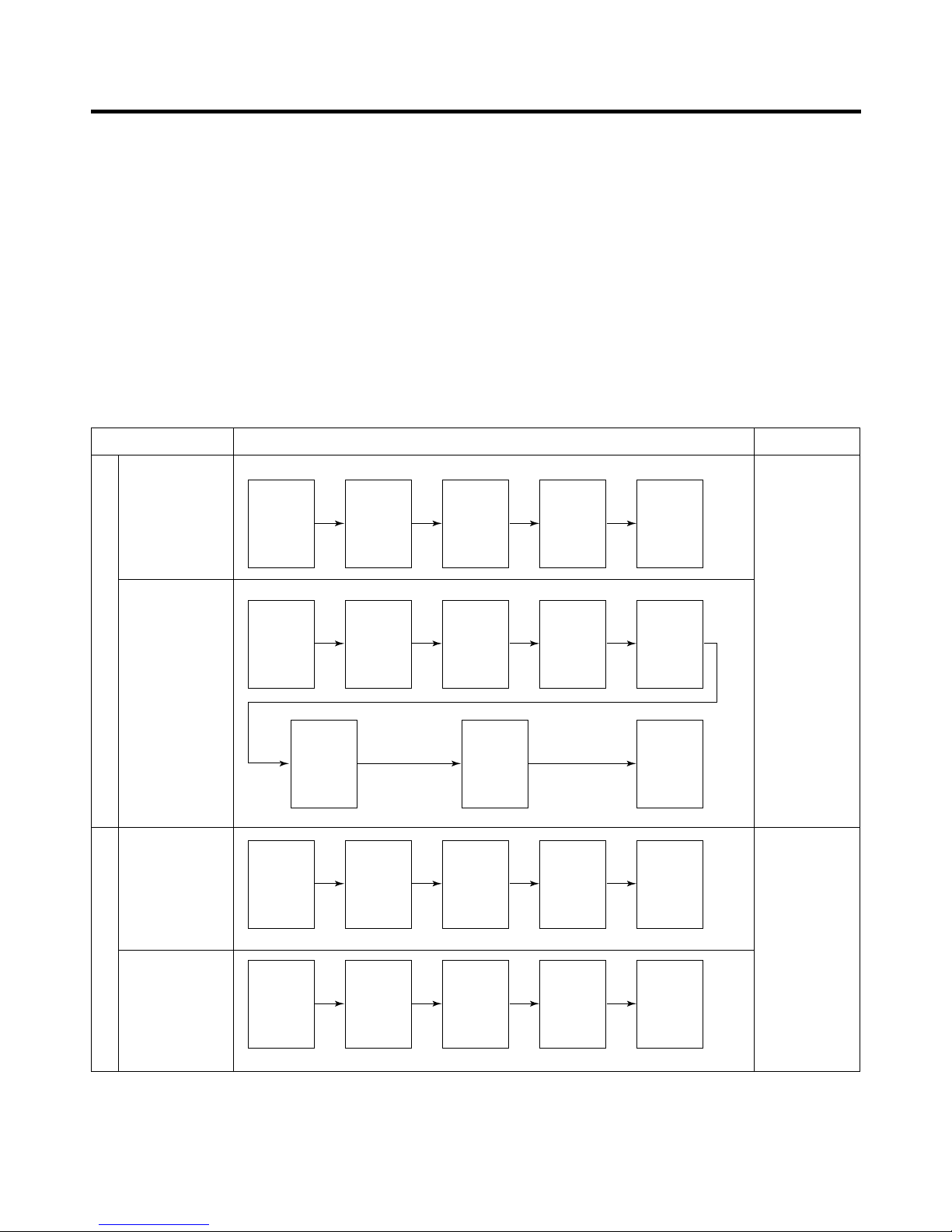
2-11. Sequential operation of built-in product
Built-in products such as compressor, frost removal heater, freezing room fan, Cooling Fan and step motor damper are
sequentially operated as follows for preventing noise and part damage occurred due to simultaneous operation of a lot of
parts in applying initial power and completing test.
MICOM FUNCTION
- 26 -
Function Load Operation Sequence Remark
In applying Initial power TEST MODE
When temperature
of a frost removal
sensor becomes
more than 45°C
(In purchase,
movement)
If error occurs
during operation,
initial operation is
not done.
If pressing switch
once more in the
test mode 2 or
temperature of a
frost removal
sensor is more
than 5°C, it
immediately
returns to the test
mode for initial
operation
(COMP operates
after 7 minutes).
When
temperature of a
frost removal
sensor becomes
less than 45°C
(In power failure,
service)
Test mode 1
(Compulsory
function)
Test mode 2
(Compulsory frost
removal)
POWER
ON
COMP
ON
COMP
ON
F-FAN
&
C-FAN
ON
F-FAN
&
C-FAN
ON
F-FAN
&
C-FAN
ON
F-FAN
&
C-FAN
OFF
STEP
MOTOR
DAMPER
ON
STEP
MOTOR
DAMPER
OPEN
STEP
MOTOR
DAMPER
CLOSE
HOME
BAR
HEATER
ON
POWER
ON
FROST
REMOVAL
HEATER
ON
HOME
BAR/
PIPE
HEATER
OFF
HOME
BAR/
PIPE
HEATER
ON
TEST
S/W
(Press
Once)
COMP
ON
TEST
S/W
(Press
2 times)
COMP
OFF
0.5
sec.
0.3
sec.
0.3
sec.
0.3
sec.
0.5
sec.
8
sec.
0.3
sec.
5
sec.
FROST
REMOVAL
HEATER
OFF
FROST
REMOVAL
HEATER
ON
WATER
SUPPLY
&
DISPENSE
HEATER
ON
5
sec.
0.3
sec.
0.3
sec.
0.3
sec.
0.3
sec.
0.3
sec.
0.3
sec.
0.3
sec.
5.6
sec.
OTHER
LOAD
OFF

2-12. Function of Trouble Diagnosis(88-LED)
1. Failure diagnosis function is function to facilitate service when nonconforming matters affecting performance of product
during use of product.
2. In occurrence of failure, pressing the function adjustment button does not perform function and only alarm sound (“Ding~”) rings.
3. If nonconforming matters occurred are released during display of failure code, MICOM returns to the original state (Reset).
4. Failure code is displayed on the display part of setting temperature for the freezing room and the display part of setting
temperature for the cold storage room of LED, which are placed at the display part of a refrigerator. All the LED graphics
other than a failure code are turned off.
✽ In display of the failure mode, all LEDs of setting temperature for freezing/ setting temperature for cold storage are turned
off (excluding Note1 and Note2).
MICOM FUNCTION
- 27 -
EXPRESS FRZ
CHILD LOCK
LOCKEXPRESS FRZ FREEZER REFRIGERATOR
FRZ TEMP REF TEMP
EXPRESS FRZ DISPENSER FREEZER REFRIGERATOR FILTER LOCK
EXPRESS
FRZ
CUBE
WATER
CRUSH FRZ TEMP REF TEMP
FILTER STATUS DISPENSER
BUTTON
ON
C
E F A B D
Failure Code Display Part
C A B D
Failure Code Display Part
●● : Normal Operation
1
2
3
4
5
6
7
8
9
10
11
Er FS
Er rS
Setting temperature
display (Note 2)
Er dS
Er dH
Er FF
Er CF
Er CO
Setting temperature
display (Note 1)
Setting temperature
display (Note 2)
Setting temperature
display (Note 2)
Failure code display part
Setting
temperature
for freezing
Setting
temperature for
cold storage
No. Item
Contents of failure
Freezer
Fan
Compressor
Stepping
motor damper
Defrost
Heater
M/C room
Fan
Product operation status in failure
Failure of freezer
sensor
Failure of refrigerator
sensor 1
Failure of refrigerator
sensor 2
Failure of frost
removal sensor
Poor of frost
removal
Failure of BLDC FAN
at freezing room
Failure of BLDC FAN
at machine room
Failure of
Communication
Failure of
Outside Sensor
Failure of ice
removal sensor
Failure of ice
maker unit
Snapping or short-circuit of
freezer sensor
Snapping or short-circuit of
refrigerator sensor 1
Snapping or short-circuit of
refrigerator sensor 2
Snapping or short-circuit of frost
removal sensor
Snapping of frost removal heater
or temperature fuse, pull-out of
connector (indicated minimum 4
hours after failure occurs)
Poor motor, hooking of wires to
fan. Contact of structures to Fan.
Snapping or short-circuit of L/wire
(if there is no fan motor signal for
more than 115 seconds in
operation of fan motor
Connection between main PCB
and display PCB. Snapping or
short-circuit of L/wire.
Transmission between main PCB
and display PCB. Poor TR and
receiving part.
Snapping or short-circuit of outside
temperature perceiving sensor
Snapping or short-circuit of icemaking sensor
Poor motor or Hall IC within ice-maker
unit. Snapping or short-circuit of
L/Wire. Poor main PCB drive circuit.
Standard
RPM
Standard
RPM
Standard
RPM
Standard
RPM
Standard
RPM
OFF
Standard
RPM
Standard
RPM
●●
●●
●●
●●
●●
●●
●●
●●
●●
OFF
●●
●●
●●
●●
ON for 15minutes
OFF for 15minutes
●●
●●
●●
●●
●●
●●
●●
●●
●●
●●
●●
●●
●●
No frost
removal
●●
●●
●●
●●
●●
●●
●●
●●
Open for 10munutes,
closing for 15 minutes
●●
●●
●●
●●
●●
●●
●●
●●
●●
MICOM FUNCTION
- 28 -
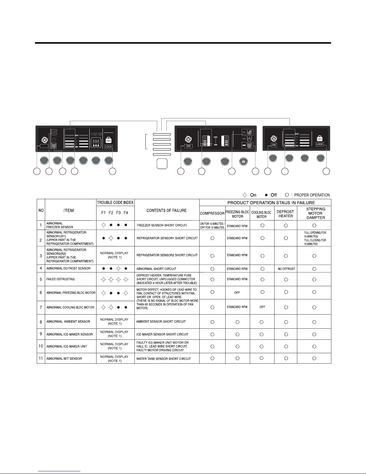
2-13. Function of Trouble Diagnosis(Bar-LED, Dot-LED)
1. Function of trouble diagnosis is to make the repair service easy when the refrigerator is out of order during service.
2. The function control button does not work but the recognition sound is heard when the refrigerator is out of order.
3. It returns to normal conditions when trouble code led is off. (reset)
4. Trouble code is indicated by the freezing temperature indicator led in the refrigerator display. All leds except trouble code
are off.
DISPENSER
Lock: Hold 3 Secs
EXPRESS FRZ FREEZER REFRIGERATOR
CUBE
WATER
CRUSH
FRZ TEMP REF TEMP
EXPRESS FRZ
EXPRESS FRZ DISPENSER FREEZER REFRIGERATOR FILTER LOCK
FRZ TEMP REF TEMP
FILTER STATUS DISPENSER
BUTTON
EXPRESS
FRZ
ON
CUBE
WATER
CRUSH
EXPRESS FRZ
CHILD LOCK
LOCKEXPRESS FRZ FREEZER REFRIGERATOR
FRZ TEMP REF TEMP
C C E FE F G GD C D
FRZ
TEMP
Trouble Code
Index
Trouble Code Trouble Code
Trouble Code
F4
F3
F2
F1
G
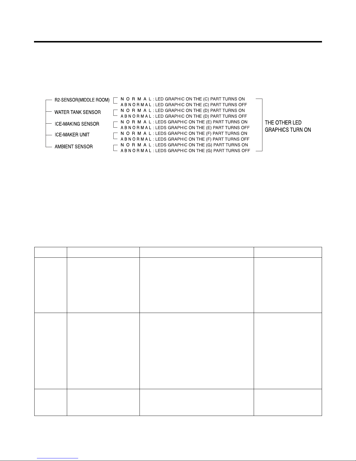
Note1) In error of outside sensor, setting temperature for freezing/ cold storage is normally displayed and indicated “Er” on
the outside temperature display part (normally displayed except for the outside temperature display part).
Note2) Nonconforming contents of poor R2 sensor, ice-making sensor and ice-making kit are displayed in LED check, not
indicated on the failure display part (when pressing freezing temperature adjustment button and special freezing
button for a second or more).
2-14. Test Function
1. The purpose of test function is to check function of the PWB and product and to search for the failure part at the failure
status.
2. Test button is placed on the main PCB of refrigerator (test switch), and the test mode will be finished after maximum 2
hours irrespective of test mode and then is reset to the normal status.
3. Function adjustment button is not perceived during performance of test mode but only warning sounds ring.
4. In finishing test mode, always pull the power cord out and then plug-in it again for the normal state.
5. If nonconforming contents such as sensor failure are found during performance of test mode, release the test mode and
display the failure code.
6. Even if pressing the test button during failure code display, test mode will not be performed.
Test 1
Test 2
Normal
Status
Mode Manipulation Content Remarks
Press test button once
(freezing force mode)
Press test button once at
the test mode 1 status
(compulsory frost removal
mode)
Press test button once at
the test mode 2 status
(freezing force mode)
1. Continuous operation of compressor
2. Continuous operation of freezing room fan
(high speed RPM) and M/C room fan
3. Frost removal heater OFF
4. Full opening status (baffle opened) status of
electronic step motor damper
5. All display LED graphics - ON.
1. Compressor OFF
2. Freezing room fan and M/C room fan is
turned off.
3. Frost removal heater ON
4. Full closing status (baffle closed) status of
electronic step motor damper
5. All display LED graphics - OFF
(88LED: Except for (A)22 (B)22 LEDs
Bar, Dot LED: Except for only middle Notch
Bar Graphics)
Return to the initial status.
Freezing room fan is
turned off in door open.
Compressor is operated
after 7 minutes.
MICOM FUNCTION
- 29 -

* LED check function- When freezer and refrigerator temperature control buttons are pressed for more than 1 second at the
same time, all LEDS on the display are on. And it returns to the normal conditions when the buttons are released.
* Check of freezer fan rpm variation- Freezer fan speed changes from high speed to standard speed and vice versa for 30
seconds whenever freezer and refrigerator temperature control buttons are pressed at the same time for more than 1
second when freezer fan is in operation and returns to the previous rpm.
2-15. Functions of Ice Dispenser and Water Dispenser
1. Ice and cold water are available without opening refrigerator door.
2. The desired ice (crushed or cube) or cold water are dispensed when dispenser press button (rubber button) is pressed
after selection of ice or cold water. When ice is selected, duct door opens by electric solenoid when dispenser press
switch is pressed. When dispenser press switch is released, duct door closes after it opens for 5 seconds.
3. Ice and water dispensing function stops when freezer door is open.
4. Geared motor and solenoid are automatically off if there is no signal after 3 minutes when ice (crushed and cube) or
water is selected and dispenser switch is pressed down. Solenoid (duct door) stops after 5 seconds when solenoid is off.
(in order to protect short circuit from solenoid heat generation)
5. Dispenser Lamp On/Off Function. The dispenser lamp shall be on or off whenever dispenser button is pressed or
released, respectively after selection of ice (crushed or cube) or water.
6. Water/Crushed Ice/Cube Ice Selection function
1) It is to select water/crushed ice/cube ice by user from the function control part and it will be indicated and selected by
pressing button.
2) Crushed ice is automatically selected when power is initially on.
3) When crushed ice is selected and its button is pressed, geared motor operates and crushed ice is dispensed.
4) When cube ice is selected and its button is pressed, geared motor and ice solenoid operate and cube ice is dispensed.
7. Function of Water Dispenser
1) When user selects water in the function control parts, it is indicated in the LED and water is selected.
2) Water dispenser is a direct tap water connection type. The water solenoid valve on the right of machine room opens
and water dispenses when user selects water and presses button.
MICOM FUNCTION
- 30 -
 Loading...