

LG GR-M712Y*A, GR-M652Y*X, GR-M712Y*Q, GR-B652Y*B, GR-B712Y*B Service Manual
...
REFRIGERATOR
SERVICE MANUAL
CAUTION
BEFORE SERVICING THE UNIT, READ THE "SAFETY
PRECAUTIONS" IN THIS MANUAL.
MODEL : GR-M652Y*A/M712Y*A GR-M652Y*X/M712Y*X
GR-M652Y*Y/M712Y*Y GR-M652Y*Q/M712Y*Q
GR-B652Y*B/B712Y*B GR-B652Y*S/B712Y*S
GR-B652Y*Y/B712Y*Y GR-B652Y*Q/B712Y*Q
GR-B652Y*C/B712Y*C
- 1 -

CONTENTS
CONTENTS ............................................................................................................................................................................. 2
SERVICING PRECAUTIONS .................................................................................................................................................. 3
SPECIFICATIONS ............................................................................................................................................................... 4-5
PARTS IDENTIFICATION .................................................................................................................................................. 6-15
FEATURE CHART ........................................................................................................................................................... 6-15
WATER DISPENSER..................................................................................................................................................... 16-17
HOME BAR ....................................................................................................................................................................... 18
DISASSEMBLY ................................................................................................................................................................ 19-20
DOOR ................................................................................................................................................................................. 19
DOOR SWITCH .................................................................................................................................................................. 19
FAN AND FAN MOTOR ..................................................................................................................................................... 19
DEF' CONTROL ASM ........................................................................................................................................................ 20
LAMP ................................................................................................................................................................................. 20
CONTROL BOX-R ............................................................................................................................................................. 20
ADJUSTMENT ................................................................................................................................................................. 21-22
COMPRESSOR ................................................................................................................................................................. 21
PTC-STARTER .................................................................................................................................................................. 21
OLP (OVER LOAD PROTECTOR) .................................................................................................................................... 22
CIRCUIT DIAGRAM .............................................................................................................................................................. 23
TROUBLESHOOTING ..................................................................................................................................................... 24-29
COMPRESSOR AND ELECTRIC COMPONENTS ........................................................................................................... 24
PTC AND OLP ................................................................................................................................................................... 25
ANOTHER ELECTRIC COMPONENT .............................................................................................................................. 26
SERVICE DIAGNOSIS CHART ......................................................................................................................................... 27
REFRIGERATING CYCLE ........................................................................................................................................... 28-29
DESCRIPTION OF FUNCTION & CIRCUIT OF MICOM ................................................................................................ 30-53
EXPLODED VIEW & REPLACEMENT PARTS LIST....................................................................................................... 54-65
SAFETY PRECAUTIONS
Please read the followings before servicing your refrigerator.
1. Check if an electric leakage occurs in the set.
2. To prevent electric shock, unplug prior to servicing.
3. In case of testing with power on, wear rubber gloves to
prevent electric shock.
4. If you use any appliances, check regular current, voltage
and capacity.
5. Don't touch metal products in cold freezer with wet hand.
It may cause frostbite.
6. Prevent water flowing to electric elements in mechanical
parts.
7. When you stand up during observing the lower part with
the upper door open, move with care to prevent head
wound which may happen by hitting the upper door.
8. When sloping the set, remove any materials on the set,
especially thin plate type. (ex.: glass shelf or books.)
9. When servicing evaporator part, wear cotton gloves
without fail. It is to prevent wound by sharp fin of
vaporator.
10.Leave a breakage of refrigerating cycle to a heavy
service center. The gas in cycle inside may soil ambient
air.
- 2 -
SERVICING PRECAUTIONS
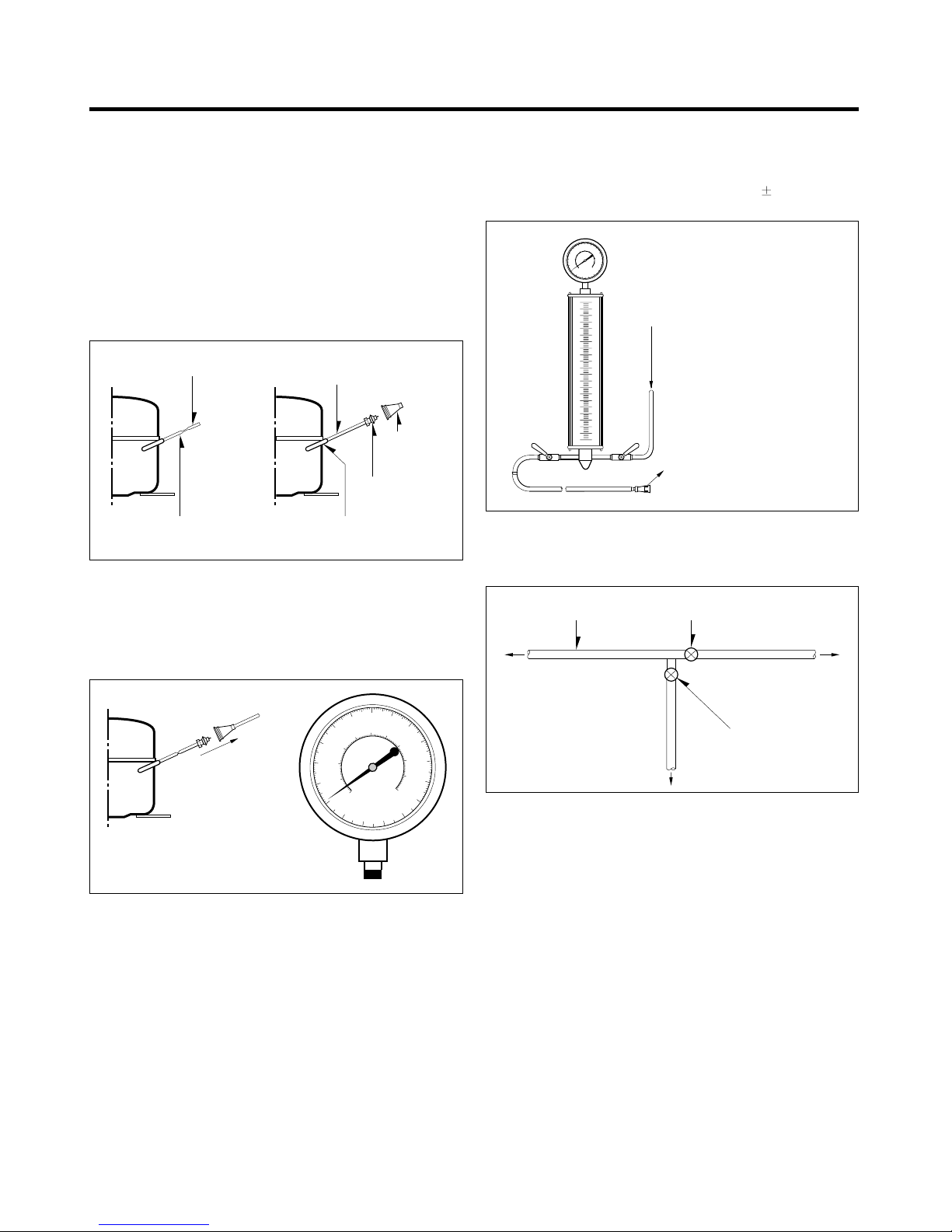
Air Recharging in Compressor
Test the refrigeration by connecting it electrically before
refilling operation. It is necessary to ascertain the function
of the motor-compressor and identify the defects
immediately. If the defects have been found, empty the old
system of eventual R-134a residue by breaking off the end
of the extension piece at its narrow point. (Figure 1)
Replace the filter and any damaged components. Unsolder
and pull off the piece remaining inside the service tube and
then attach an extension completely with male Hansen and
last, solder it to the same tube again. (Figure 2)
POINT TO BE
BROKEN
SERVICE TUBE EXTENSION SOLDERING POINT
CHARGE TUBE
EXTENSION
MALE HANSEN
FEMALE
HANSEN
Figure 1 Figure 2
It is necessary to execute the soldering operation with valve
open so that the fumes caused by oil residue can come out
freely without blowholes between two tubes during heating
the point to be soldered.
The extension fitted with the male Hansen is connected to
the female fitting of the vacuum pump tube. (Figure 3)
is over, add the quantity in grams of R-134a to the
refrigerant system. Remember that every system has an
exact quantity of R-134a with a tolerance of
5 grams that
can be added. (Figure 4)
TO THE R-134a CYLINDER
TO THE REFRIGERATION
SYSTEM
Figure 4
Before performing this operation (if the vacuum pump and
refilling cylinder are connected), make sure that the valve
placed between the vacuum pump and refilling tube are
closed to keep the Freon for adding to the system. (Figure 5)
FILLING OR
CHARGE TUBE
TO THE REFRIGERATION
SYSTEM
VALVE TO BE OPENED
WHEN REFILLING
TO THE CHARGE
CYLINDER
TO THE
VACUUM PUMP
PRESSURE
GAUGE
Air evacuating from the system begins so soon as the pump
starts. The refrigeration system must be kept under vacuum
until the reading on the low-pressure gauge indicates
vacuum (0 absolute, -1 atm., -760 mm hg) in any case it is
advisable to keep the pump running for about 60 minutes.
(Figure 3)
In case that a considerable leakage occurs and to stop the
vacuum pump will be necessary and add a small quantity of
Freon to the system, if vacuum should not be obtained
(pressure gauge can't fall to 1 atmosphere), start the
refrigeration unit and find the leakage with the special leakfinder. When the defective soldering point is visible, re-do it
after opening the extension tube valve and reestablishing
the normal outside pressure inside the group.
Because the melted alloy is sucked into the tubes and block
them, the pressure must be rebalanced when vacuum is in
the system in soldering. As soon as the vacuum operation
Figure 3
VALVE TO BE CLOSED
AFTER VACUUM
TO THE VACUUM PUMP
Figure 5
In addition, check the graduated scale on the cylinder for
the quantity of R-134a to be added, for example, if we have
750 grams of Freon in the cylinder and must add 165 grams
to the group, this amount will be reached when R-134a has
dropped to 585 grams, remembering that the indicator
shows a lower limit of meniscus. Do this after choosing the
scale corresponding to the gas pressure different scales
reported as the same gas pressure indicated by the
pressure gauge on the top of the column.
To make R-134a flow into the system, open the valve
placed at the base of the cylinder and connected to the
filling tube. The amount of Freon cannot be added to the
system all at once because it may cause a blocking of
motor-compressor. Therefore, proceed by adding original
quantity of about 20-30 grams and close the valve
immediately.
The pressure rises and the motor-compressor must start,
sucking the gas and making the pressure go down again.
Regulate the valve again, maintaining the same manner
until reaching to the quantity of R-134a established for the
system being charged. When the system is running, the
suction pressure must be stabilized between 0.10 to 0.4
atmosphere.
- 3 -
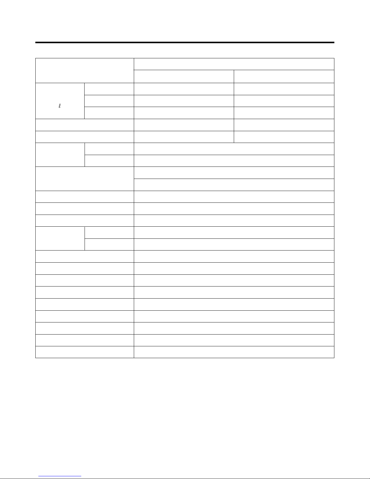
1. SPECIFICATIONS
ITEMS
FREEZER
NET CAPACITY
)
(
DIMENSIONS (mm)
NET WEIGHT (kg)
TEMPERATURE
CONTROL
DEFROSTING SYSTEM
OUT CASE
INNER CASE
INSULATION
SHELF
REFRIGERATOR
TOTAL
FREEZER
REFRIGERATOR
FREEZER
REFRIGERATOR
SPECIFICATIONS
GR-M712Y*A/ M712Y*X/ M712Y*Y,
GR-B712Y*Y/ B712Y*Q/ B712Y*C
157
409
566
860(W) X 750.5(D) X 1794(H)
97
Knob Dial
Micom Control
Full Automatic
Heater Defrost
Pre Coated Metal
Cyclo-Pentane Foam
2 EA/ 3EA(Option)
GR-B712Y*B/ B712Y*S
157
393
550
860(W) X 750.5(D) X 1794(H)
96
A B S
1 EA
VEGETABLE TRAY
EGG TRAY
ICE TRAY
ICE BANK
COMPRESSOR
EVAPORATOR
CONDENSER
REFRIGERANT
DEFROSTING DEVICE
Drawer Type
1 Piece
2 Piece
1 Piece
P.T.C Starting Type
Fin Tube Type
Wire Condenser / Screw Condenser
R134a (140g) / R600a (69g)
Heater
- 4 -
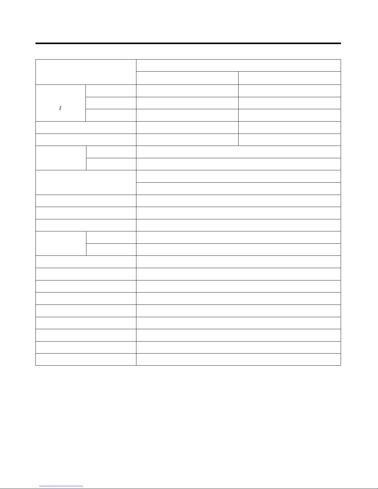
NET CAPACITY
)
(
ITEMS
FREEZER
REFRIGERATOR
TOTAL
SPECIFICATIONS
GR-M652Y*A/ M652Y*X/ M652Y*Y,
GR-B652Y*C/ B652Y*Y/ B652Y*Q
151
394
545
GR-B652Y*B/ B652Y*S
151
378
529
DIMENSIONS (mm)
NET WEIGHT (kg)
TEMPERATURE
CONTROL
DEFROSTING SYSTEM
OUT CASE
INNER CASE
INSULATION
SHELF
VEGETABLE TRAY
EGG TRAY
ICE TRAY
ICE BANK
FREEZER
REFRIGERATOR
FREEZER
REFRIGERATOR
860(W) X 730.5(D) X 1794(H)
95
Pre Coated Metal
Cyclo-Pentane Foam
2 EA/ 3EA(Option)
860(W) X 730.5(D) X 1794(H)
94
Knob Dial
Micom Control
Full Automatic
Heater Defrost
A B S
1 EA
Drawer Type
1 Piece
2 Pieces
1 Piece
COMPRESSOR
EVAPORATOR
CONDENSER
REFRIGERANT
DEFROSTING DEVICE
P.T.C Starting Type
Fin Tube Type
Wire Condenser / Screw Condenser
R134a (140g) / R600a (69g)
Heater
- 5 -

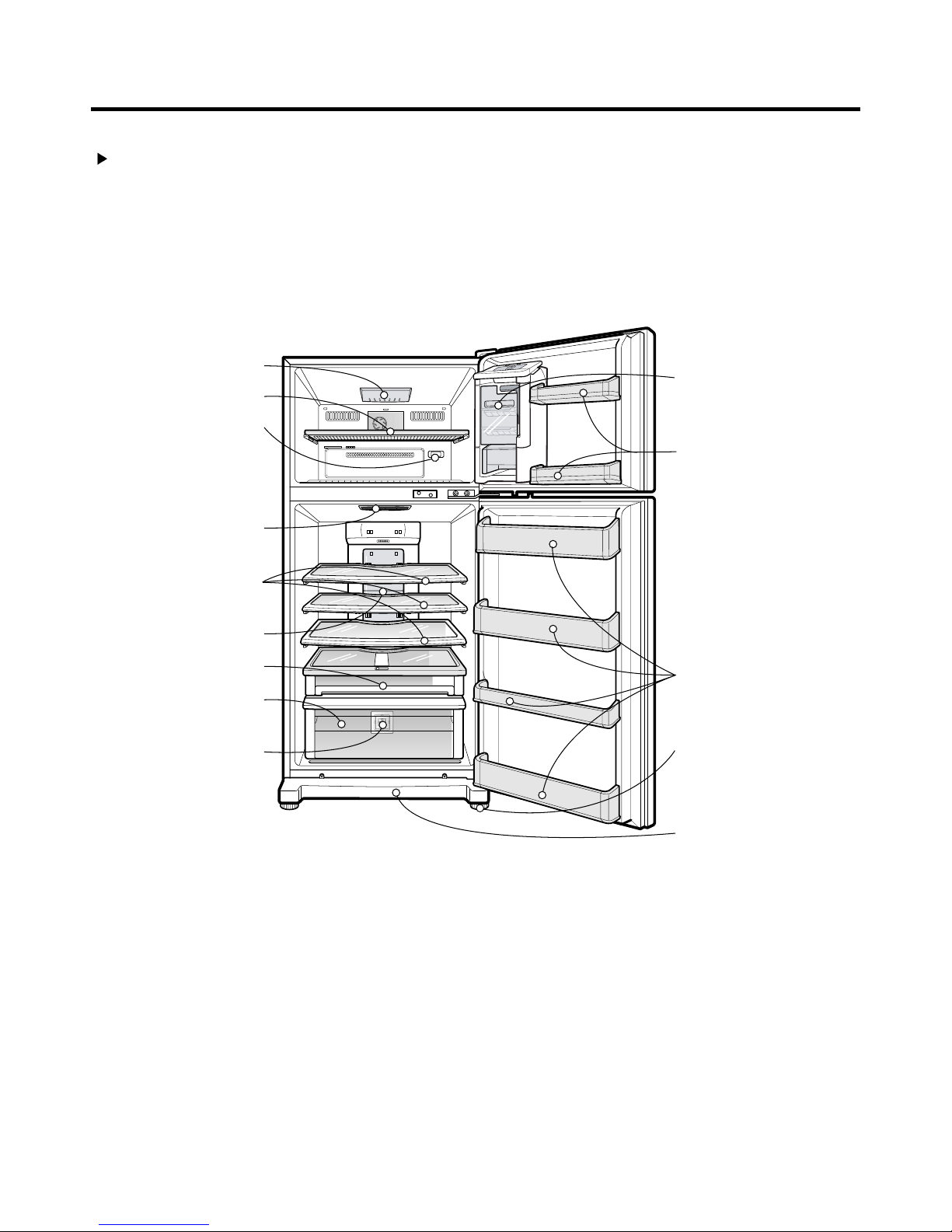
2. PARTS IDENTIFICATION
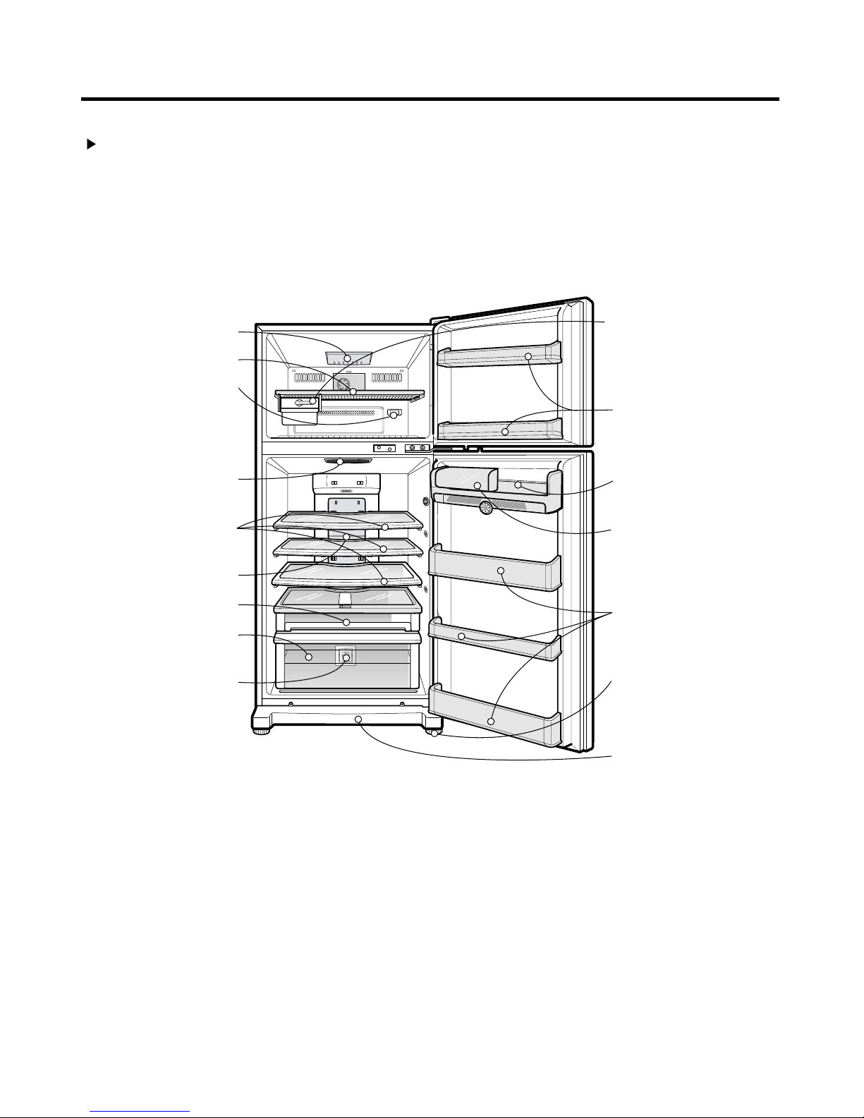
2-1. FEATURE CHART
GR-M652Y*A/M712Y*A, GR-M652Y*X/M712Y*X
FREEZER
COMPARTMENT
Lamp
Shelf
Freezer Temperature
Control Dial
REFRIGERATOR
COMPARTMENT
Deodorizer
(Optional)
Shelves
(Optional)
In-Door Ice
Maker
Freezer Door Rack
Egg Storage Rack
Dairy Corner
Lamp
Convertible Room
Vegetable Drawer
Vita Light
Refrigerator Door
Rack
Levelling Screw
Vegetable Partitioner
(Optional)
Base Cover
NOTE : This guide covers several different models.The refrigerator you have
purchased may have some or all of the features shown above.
- 6 -

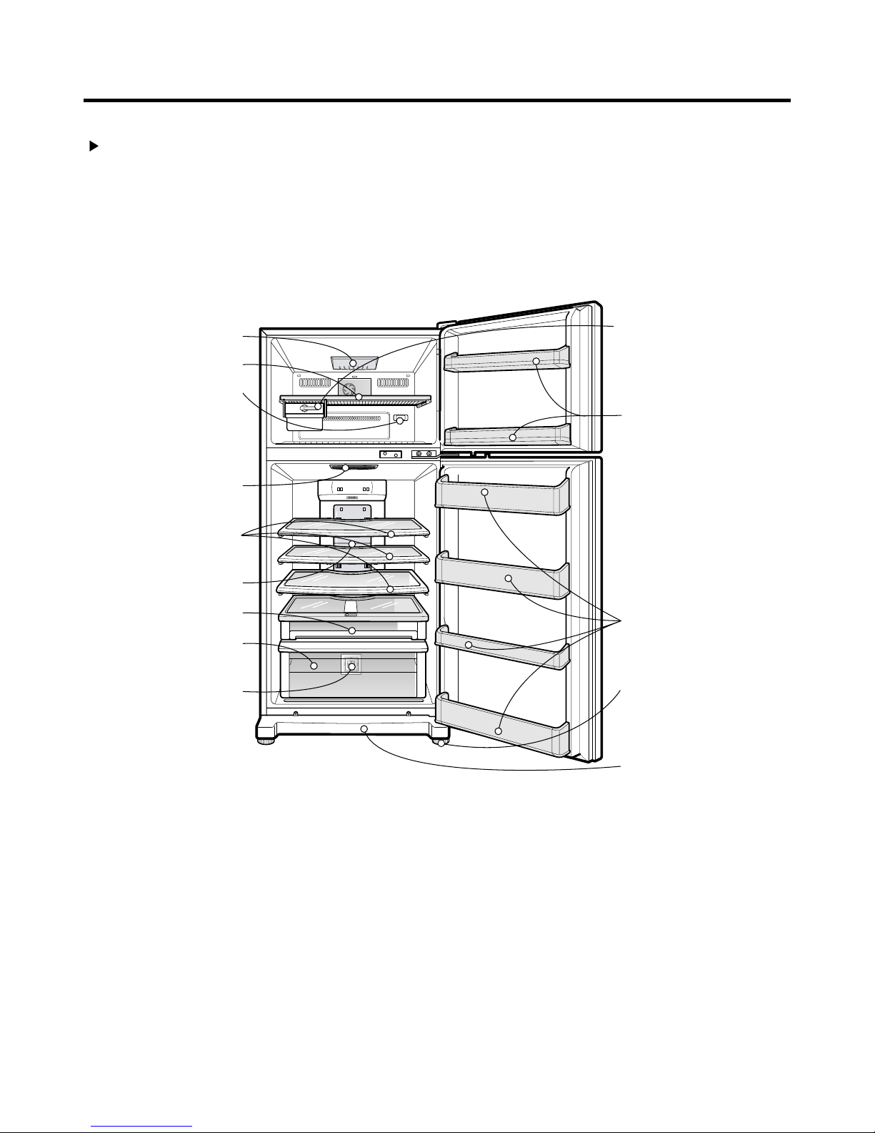
GR-M652Y*Y/M712Y*Y
FREEZER
COMPARTMENT
Lamp
Shelf
Freezer Temperature
Control Dial
REFRIGERATOR
COMPARTMENT
Deodorizer
(Optional)
Shelves
(Optional)
Lamp
Convertible Room
Vegetable Drawer
Vitamin Kit(optional)
In-Door Ice
Maker
Freezer Door Rack
Egg Storage Rack
Dairy Corner
Refrigerator Door
Rack
Levelling Screw
NOTE : This guide covers several different models.The refrigerator you have
Base Cover
purchased may have some or all of the features shown above.
- 7 -
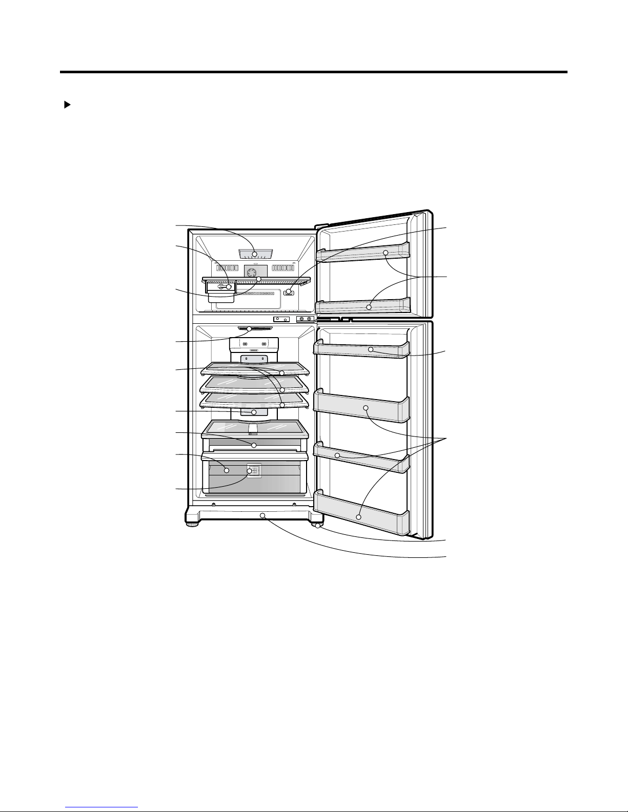
GR-B652Y*Y/B712Y*Y
FREEZER
COMPARTMENT
Lamp
Shelf
Freezer Temperature
Control Dial
REFRIGERATOR
COMPARTMENT
Deodorizer
(Optional)
Shelves
(Optional)
Lamp
Convertible Room
Vegetable Drawer
Vitamin Kit(optional)
In-Door Ice
Maker
Freezer Door Rack
Refrigerator Door
Rack
Levelling Screw
NOTE : This guide covers several different models.The refrigerator you have
Base Cover
purchased may have some or all of the features shown above.
- 8 -
GR-M652Y*Q/M712Y*Q
FREEZER
COMPARTMENT
Lamp
Shelf
Freezer Temperature
Control Dial
REFRIGERATOR
COMPARTMENT
Deodorizer
(Optional)
Twigting Ice Serve
Freezer Door Rack
Egg Storage Rack
Shelves
(Optional)
Lamp
Convertible Room
Vegetable Drawer
Vitamin Kit(optional)
Dairy Corner
Refrigerator Door
Rack
Levelling Screw
Base Cover
NOTE : This guide covers several different models.The refrigerator you have
purchased may have some or all of the features shown above.
- 9 -
GR-B652Y*Q/B712Y*Q
FREEZER
COMPARTMENT
Lamp
Shelf
Freezer Temperature
Control Dial
REFRIGERATOR
COMPARTMENT
Deodorizer
(Optional)
Shelves
(Optional)
Twigting Ice Serve
Freezer Door Rack
Lamp
Convertible Room
Vegetable Drawer
Vitamin Kit(optional)
Refrigerator Door
Rack
Levelling Screw
Base Cover
NOTE : This guide covers several different models.The refrigerator you have
purchased may have some or all of the features shown above.
- 10 -

GR-B652Y*B/B712Y*B
FREEZER
COMPARTMENT
Lamp
Shelf
Freezer Temperature
Control Dial
REFRIGERATOR
COMPARTMENT
Deodorizer
(Optional)
Shelves
(Optional)
Lamp
Convertible Room
Vegetable Drawer
Vita Light
In-Door Ice
Maker
Freezer Door Rack
Water Tank
Refrigerator Door
Rack
NOTE : This guide covers several different models.The refrigerator you have
Levelling Screw
Base Cover
purchased may have some or all of the features shown above.
- 11 -

GR-B652Y*S/B712Y*S
FREEZER
COMPARTMENT
Lamp
Shelf
Freezer Temperature
Control Dial
REFRIGERATOR
COMPARTMENT
Deodorizer
(Optional)
Shelves
(Optional)
Lamp
Convertible Room
Vegetable Drawer
Vitamin Kit(optional)
In-Door Ice
Maker
Freezer Door Rack
Water Tank
Refrigerator Door
Rack
NOTE : This guide covers several different models.The refrigerator you have
Levelling Screw
Base Cover
purchased may have some or all of the features shown above.
- 12 -

GR-B652Y*P/B712Y*P
FREEZER
COMPARTMENT
Lamp
Shelf
Freezer Temperature
Control Dial
REFRIGERATOR
COMPARTMENT
Deodorizer
(Optional)
Shelves
(Optional)
Lamp
Convertible Room
Vegetable Drawer
Vitamin Kit(optional)
Twigting Ice Serve
Freezer Door Rack
Water Tank
Refrigerator Door
Rack
NOTE : This guide covers several different models.The refrigerator you have
Levelling Screw
Base Cover
purchased may have some or all of the features shown above.
- 13 -
GR-B652Y*C/B712Y*C
FREEZER
COMPARTMENT
Lamp
Twigting Ice Serve
Shelf
REFRIGERATOR
COMPARTMENT
Deodorizer
(Optional)
Shelves
(Optional)
Freezer Temperature
Control Dial
Freezer Door Rack
Egg Storage Rack
Lamp
Convertible Room
Vegetable Drawer
Vitamin Kit(optional)
Refrigerator Door
Rack
Levelling Screw
Base Cover
NOTE : This guide covers several different models.The refrigerator you have
purchased may have some or all of the features shown above.
- 14 -

GR-M652Y*C/M712Y*C
FREEZER
COMPARTMENT
Lamp
Twigting Ice Serve
Shelf
REFRIGERATOR
COMPARTMENT
Deodorizer
(Optional)
Shelves
(Optional)
Freezer Temperature
Control Dial
Freezer Door Rack
Egg Storage Rack
Dairy Corner
Lamp
Convertible Room
Vegetable Drawer
Vitamin Kit(optional)
Refrigerator Door
Rack
Levelling Screw
Base Cover
NOTE : This guide covers several different models.The refrigerator you have
purchased may have some or all of the features shown above.
- 15 -
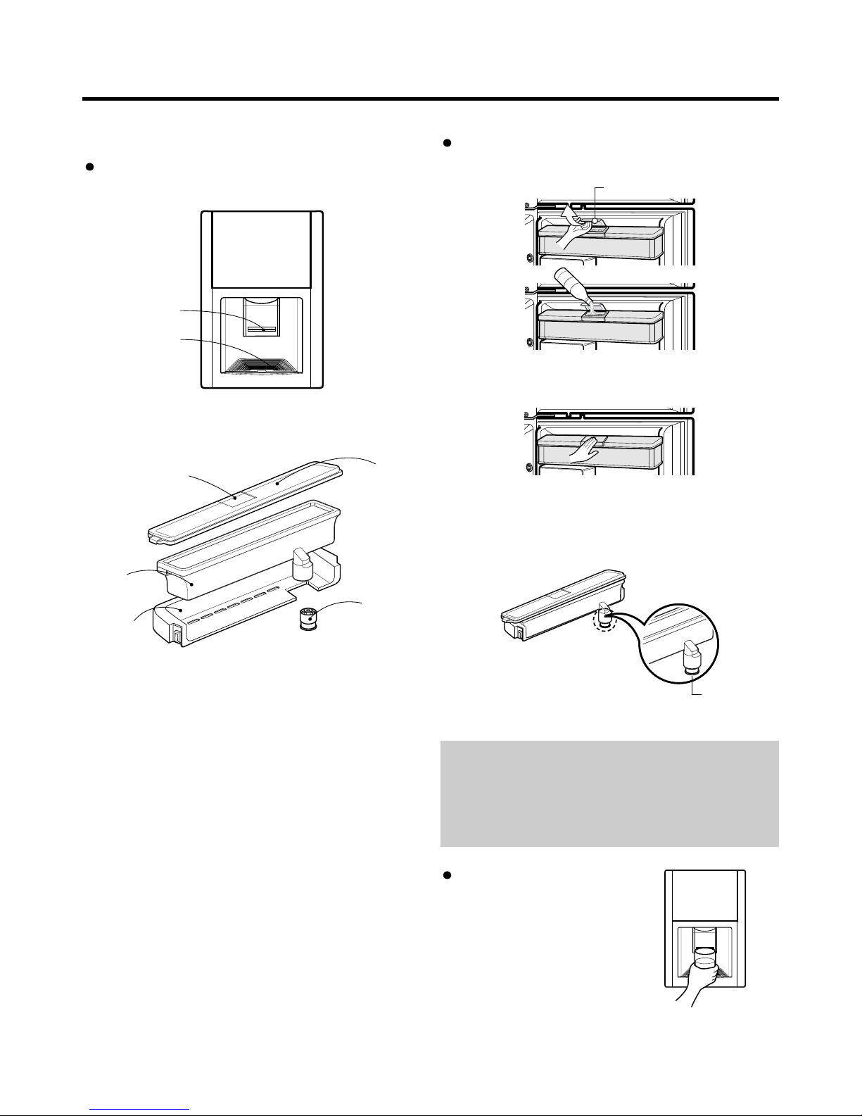
2-2 WATER DISPENSER
Putting The Water In The Water Tank
Features 1. Open the cover cap and pour water into the water tank.
Cover Cap
DISPENSER
PAD
GRILLE
2. Close the cover cap.
WATER
TANK
REFRIG
ERATOR
DOOR
RACK
Cover Cap
Tank
Cover
3. Make sure that the valve under the water tank is in
position. Push the connecting part into the hole.
VALVE
WATER TANK
VALVE
CAUTION
1. Do not use anything other than water including soft
drinks, milk and juices.
2. Hot water needs to be cooled before being put in the
water tank.
Drinking
1. Press the dispenser pad
with the glass.
2. The water is released when
the dispenser pad is
pressed. The pad returns to
its original position when
the glass is removed, and
the water stops its flow.
- 16 -
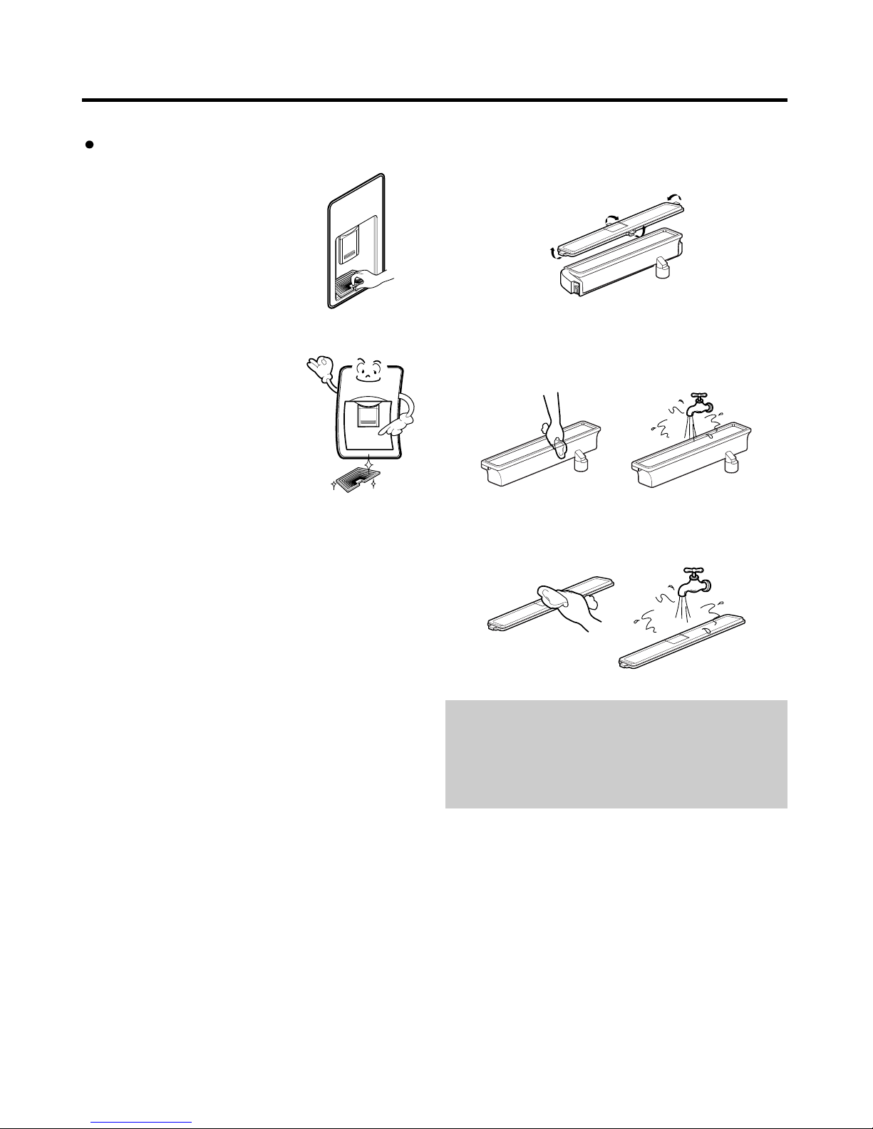
Cleaning
Grille and Drip Tray
1. Remove with the grille.
2. Wash the grille with a mild
detergent and rinse
thoroughly.
Water Tank
1. Remove the Cover.
2. Clean the inside and outside of the water tank with
dishwashing detergent and rinse thoroughly under
running water.
3. Clean the tank cover with dishwashing detergent and
rinse thoronghly under running water.
CAUTION
1. Use lukewarm water when cleaning.
2. Do not use anything other than water. If it is used with
soft drinks, put water in the water tank and discharge
three or four cups of water shortly.
- 17 -
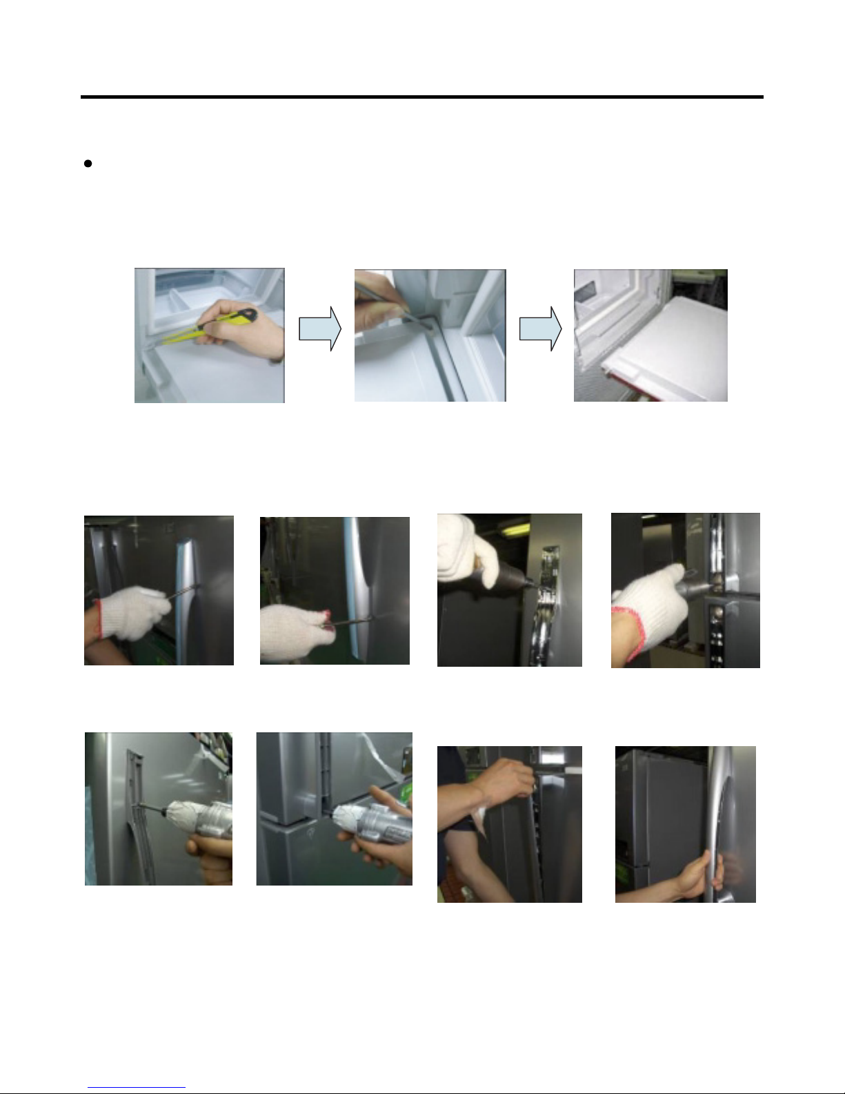
2-3 HOME BAR
How to disassemble and assemble the ice access door (H/BAR Door)
1) Open the ice access door to carefully remove left rubber packing.
2) While pressing the hinge separated using a pointed tool (driver, drill), move it to the right and carefully separate the ice
access door.
3) The assembly is made in reverse order.
1) 2) 3)
2-4 HOW TO DISASSEMBLE AND ASSEMBLE HANDLE
1. Disassemble the handle, deco and handle, base
1) Remove handle, deco by pulling it out with tooling.
2. Assemble the new handle, deco and handle, base
1) Assemble new handle, base by tightening 3 screws.
Freezer handle
2) Remove handle, base by loosening 3 screws.
Upper (1 screw)
Refrigerator handle
Upper (1 screw) Lower (2 screws)
2) Assemble handle, deco by pushing it after inserting
upper and lower part first.
Lower (2 screws)
- 18 -
 Loading...