

LG GR-282MF Owner’s Manual
SERVICING PRECAUTIONS
Air Recharging in Compressor
Test the refrigeration by connecting itelectrically before
refilling operation. It is necessary to ascertain the function
of the motor*compressor and identify the defects
immediately. If the defects have been found, empty the old
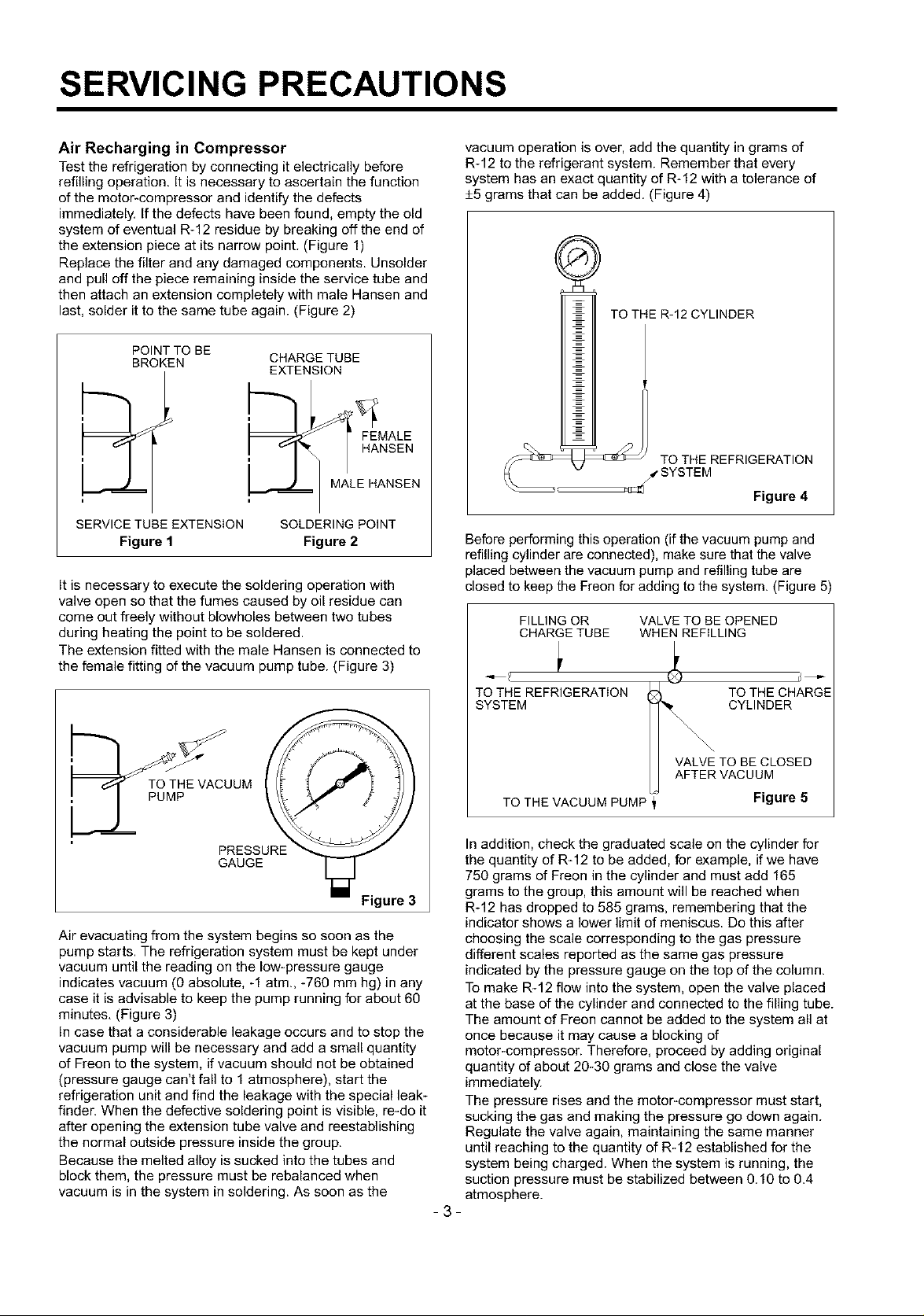
system of eventual R-12 residue by breaking off the end of
the extension piece at its narrow point. (Figure 1)
Replace the filter and any damaged components. Unsolder
and pull off the piece remaining inside the service tube and
then attach an extension completely with male Hansen and
last, solder it to the same tube again. (Figure 2)
POINTTO BE
BROKEN
SERVICE TUBE EXTENSION
Figure 1
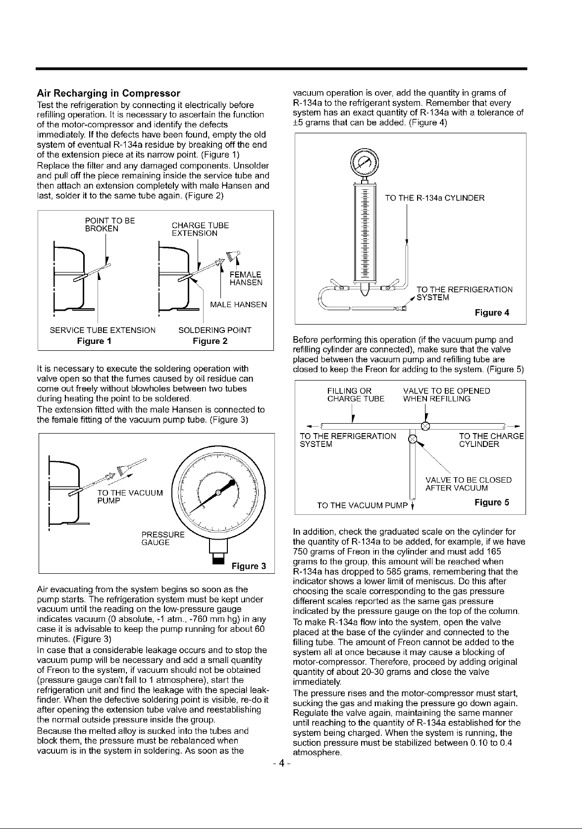
It is necessary to execute the soldering operation with
valve open so that the fumes caused by oil residue can
come out freely without blowholes between two tubes
during heating the point to be soldered.
The extension fitted with the male Hansen is connected to
the female fitting of the vacuum pump tube. (Figure 3)
CHARGE TUBE
EXTENSION
MALE HANSEN
SOLDERING POINT
Figure 2
vacuum operation is over, add the quantity in grams of
R-12 to the refrigerant system. Remember that every
system has an exact quantity of R-12 with a tolerance of
+5 grams that can be added. (Figure 4)
TO THE R-12CYLINDER
_= J_ TOsTTHEEMREgRIGERATION
Figure 4
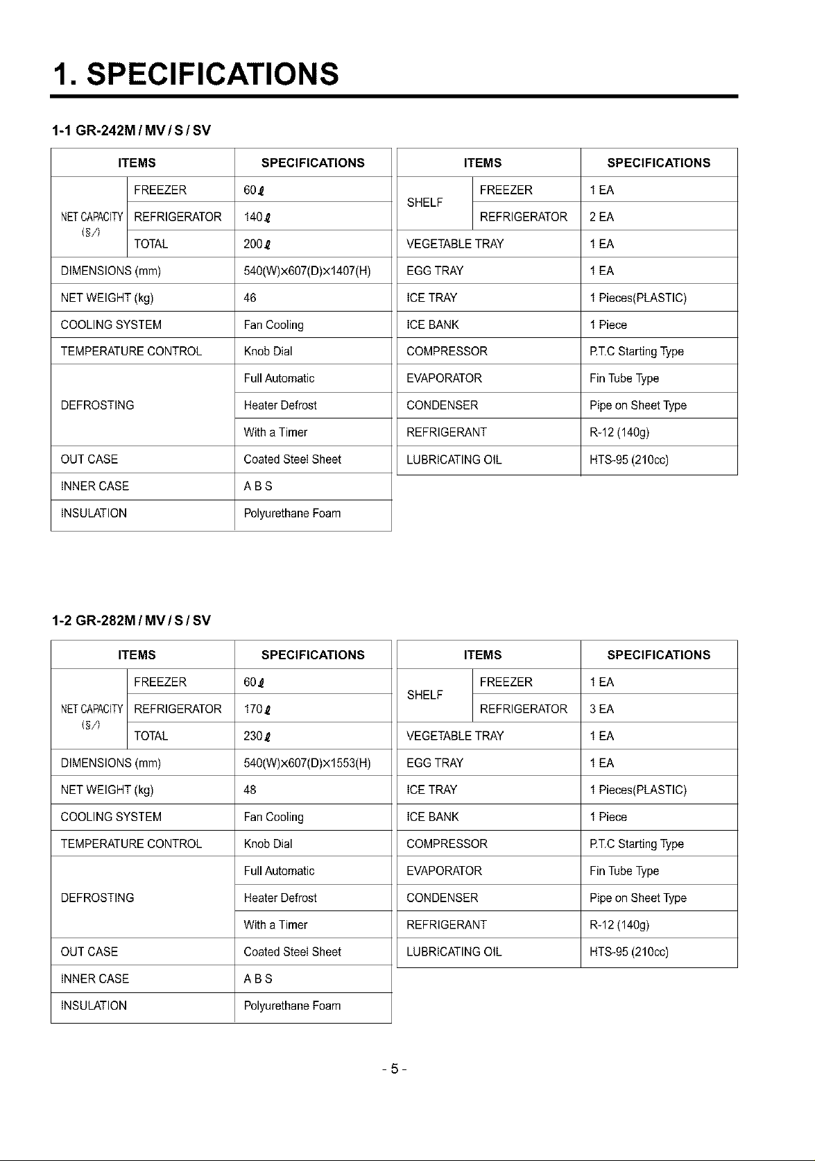
Before performing this operation (if the vacuum pump and
refilling cylinder are connected), make sure that the valve
placed between the vacuum pump and refilling tube are
closed to keep the Freon for adding to the system. (Figure 5)
FILLING OR VALVE TQ BE OPENED
CHARGE TUBE WHEN REFILLING
TO THE REFRIGERATION TO THE CHARGE
SYSTEM CYLINDER
puOMT_ cUUM
PRESSURE
GAUGE
Figure 3
Air evacuating from the system begins so soon as the
pump starts. The refrigeration system must be kept under
vacuum until the reading on the low-pressure gauge
indicates vacuum (0 absolute, -1 atm., -760 mm hg) in any
case it is advisable to keep the pump running for about 60
minutes. (Figure 3)
In case that a considerable leakage occurs and to stop the
vacuum pump will be necessary and add a small quantity
of Freon to the system, if vacuum should not be obtained
(pressure gauge can't fall to 1 atmosphere), start the
refrigeration unit and find the leakage with the special leak-
finder. When the defective soldering point is visible, re-do it
after opening the extension tube valve and reestablishing
the normal outside pressure inside the group.
Because the melted alloy is sucked into the tubes and
block them, the pressure must be rebalanced when
vacuum is in the system in soldering. As soon as the
VALVE TO BE CLOSED
AFTER VACUUM
TO THE VACUUM PUMP
In addition, check the graduated scale on the cylinder for
the quantity of R-12 to be added, for example, if we have
750 grams of Freon in the cylinder and must add 165
grams to the group, this amount will be reached when
R-12 has dropped to 585 grams, remembering that the
indicator shows a lower limit of meniscus. Do this after
choosing the scale corresponding to the gas pressure
different scales reported as the same gas pressure
indicated by the pressure gauge on the top of the column.
To make R-12 flow into the system, open the valve placed
at the base of the cylinder and connected to the filling tube.
The amount of Freon cannot be added to the system all at
once because it may cause a blocking of
motor-compressor. Therefore, proceed by adding original
quantity of about 20-30 grams and close the valve
immediately.
The pressure rises and the motor-compressor must start,
sucking the gas and making the pressure go down again.
Regulate the valve again, maintaining the same manner
until reaching to the quantity of R-12 established for the
system being charged. When the system is running, the
suction pressure must be stabilized between 0.10 to 0.4
atmosphere.
Figure 5
-3-
Air Recharging in Compressor
Test the refrigeration by connecting it electrically before
refilling operation. It is necessary to ascertain the function
of the motor*compressor and identify the defects
immediately, If the defects have been found, empty the old
system of eventual R-134a residue by breaking off the end
of the extension piece at its narrow point. (Figure 1)
Replace the filter and any damaged components. Unsolder
and pull off the piece remaining inside the service tube and
then attach an extension completely with male Hansen and
last, solder it to the same tube again. (Figure 2)
vacuum operation is over, add the quantity in grams of
R-134a to the refrigerant system. Remember that every
system has an exact quantity of R-134a with a tolerance of
+5 grams that can be added. (Figure 4)
POINTTO BE
BROKEN
CHARGE TUBE
EXTENSION
MALE HANSEN
SERVICE TUBE EXTENSION
Figure 1
SOLDERING POINT
Figure 2
It is necessary to execute the soldering operation with
valve open so that the fumes caused by oil residue can
come out freely without blowholes between two tubes
during heating the point to be soldered.
The extension fitted with the male Hansen is connected to
the female fitting of the vacuum pump tube. (Figure 3)
UM
_i TO TiE R-134a CYLINDER
__ TyOsTTHEEMREFRIGERATiON
Figure 4
Before performing this operation (if the vacuum pump and
refilling cylinder are connected), make sure that the valve
placed between the vacuum pump and refilling tube are
closed to keep the Freon for adding to the system. (Figure 5)
FILLING OR VALVE TO BE OPENED
CHARGE TUBE WHEN REFILLING
TO THE REFRIGERATION TO THE CHARGE
SYSTEM CYLINDER
VALVE TO BE CLOSED
AFTER VACUUM
TO THE VACUUM PUMP
Figure 5
PRESSURE
GAUGE
Figure 3
Air evacuating from the system begins so soon as the
pump starts. The refrigeration system must be kept under
vacuum until the reading on the low-pressure gauge
indicates vacuum (0 absolute, -1 atm., -760 mm hg) in any
case it is advisable to keep the pump running for about 60
minutes. (Figure 3)
In case that a considerable leakage occurs and to stop the
vacuum pump will be necessary and add a small quantity
of Freon to the system, if vacuum should not be obtained
(pressure gauge can't fall to 1 atmosphere), start the
refrigeration unit and find the leakage with the special leak-
finder. When the defective soldering point is visible, re-do it
after opening the extension tube valve and reestablishing
the normal outside pressure inside the group.
Because the melted alloy is sucked into the tubes and
block them, the pressure must be rebalanced when
vacuum is in the system in soldering. As soon as the
In addition, check the graduated scale on the cylinder for
the quantity of R-134a to be added, for example, if we have
750 grams of Freon in the cylinder and must add 165
grams to the group, this amount will be reached when
R-134a has dropped to 585 grams, remembering that the
indicator shows a lower limit of meniscus. Do this after
choosing the scale corresponding to the gas pressure
different scales reported as the same gas pressure
indicated by the pressure gauge on the top of the column.
To make R-134a flow into the system, open the valve
placed at the base of the cylinder and connected to the
filling tube. The amount of Freon cannot be added to the
system all at once because it may cause a blocking of
motor-compressor. Therefore, proceed by adding original
quantity of about 20-30 grams and close the valve
immediately.
The pressure rises and the motor-compressor must start,
sucking the gas and making the pressure go down again.
Regulate the valve again, maintaining the same manner
until reaching to the quantity of R-134a established for the
system being charged. When the system is running, the
suction pressure must be stabilized between 0.10 to 0.4
atmosphere.
-4-
1. SPECIFICATIONS
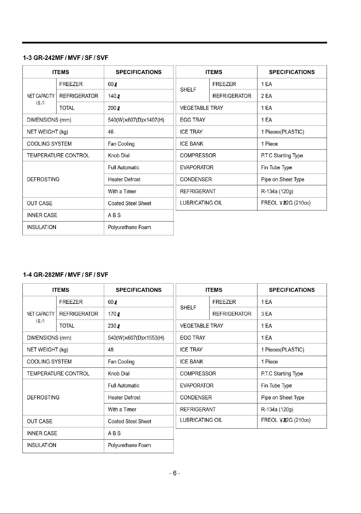
1-1 GR-242M / MV/S/SV
ITEMS
FREEZER
NETCAPACITY
(§/)
DIMENSIONS (mm)
NET WEIGHT (kg)
COOLING SYSTEM
TEMPERATURE CONTROL
DEFROSTING
OUT CASE
INNER CASE
INSULATION
REFRIGERATOR
TOTAL
SPECIFICATIONS
60_
140_
200_
540(W)x607(D)x1407(H)
46
FanCooling
Knob Dial
Full Automatic
Heater Defrost
With a Timer
Coated SteeI Sheet
ABS
Polyurethane Foam
ITEMS
FREEZER
SHELF
REFRIGERATOR
VEGETABLETRAY
EGG TRAY
ICETRAY
ICE BANK
COMPRESSOR
EVAPORATOR
CONDENSER
REFRIGERANT
LUBRICATING OIL
SPECIFICATIONS
1 EA
2 EA
1 EA
1 EA
1 Pieces(PLASTIC)
1 Piece
RT.C Starting Type
Fin Tube Type
Pipe on Sheet Type
R-12 (140g)
HTS-95 (210cc)
1-2 GR-282M I MV I SI SV
ITEMS
FREEZER
NETCAPACITY
DIMENSIONS (mm)
NET WEIGHT (kg)
COOLING SYSTEM
TEMPERATURE CONTROL
DEFROSTING
OUT CASE
INNER CASE
INSULATION
REFRIGERATOR
TOTAL
SPECIFICATIONS
60.12
170_
230_
540(W)x607(D)x1553(H)
48
FanCooling
Knob Dial
Full Automatic
Heater Defrost
With a Timer
Coated SteeI Sheet
ABS
Polyurethane Foam
ITEMS
FREEZER
SHELF
REFRIGERATOR
VEGETABLETRAY
EGG TRAY
ICE TRAY
ICE BANK
COMPRESSOR
EVAPORATOR
CONDENSER
REFRIGERANT
LUBRICATING OIL
SPECIFICATIONS
1 EA
3 EA
1 EA
1 EA
1 Pieces(PLASTIC)
1 Piece
RT.C Starting Type
Fin Tube Type
Pipe on Sheet Type
R-12 (140g)
HTS-95 (210cc)
-5-
1-3 GR-242MF / MVF / SF / SVF
ITEMS
FREEZER
NETCAPACITY
(§/)
DIMENSIONS (mm)
NET WEIGHT (kg)
COOLING SYSTEM
TEMPERATURE CONTROL
DEFROSTING
OUT CASE
INNER CASE
INSULATION
REFRIGERATOR
TOTAL
SPECIFICATIONS
60_
140_
200_
540(W)x607(D)x1407(H)
46
FanCooling
Knob Dial
Full Automatic
Heater Defrost
With a Timer
Coated SteeI Sheet
ABS
Polyurethane Foam
ITEMS
FREEZER
SHELF
REFRIGERATOR
VEGETABLETRAY
EGG TRAY
ICETRAY
ICE BANK
COMPRESSOR
EVAPORATOR
CONDENSER
REFRIGERANT
LUBRICATING OIL
SPECIFICATIONS
1 EA
2 EA
1 EA
1 EA
1 Pieces(PLASTIC)
1 Piece
RT.C Starting Type
Fin Tube Type
Pipe on Sheet Type
Rq34a (120g)
FREOL ¥_2G (210cc)
1-4 GR-282MF / MVF / SF / SVF
ITEMS
FREEZER
NETCAPACITY
DIMENSIONS (mm)
NET WEIGHT (kg)
COOLING SYSTEM
TEMPERATURE CONTROL
DEFROSTING
OUT CASE
INNER CASE
INSULATION
REFRIGERATOR
TOTAL
SPECIFICATIONS
60.12
170_
230_
540(W)x607(D)x1553(H)
48
FanCooling
Knob Dial
Full Automatic
Heater Defrost
With a Timer
Coated SteeI Sheet
ABS
Polyurethane Foam
ITEMS
FREEZER
SHELF
REFRIGERATOR
VEGETABLETRAY
EGG TRAY
ICE TRAY
ICE BANK
COMPRESSOR
EVAPORATOR
CONDENSER
REFRIGERANT
LUBRICATING OIL
SPECIFICATIONS
1 EA
3 EA
1 EA
1 EA
1 Pieces(PLASTIC)
1 Piece
RT.C Starting Type
Fin Tube Type
Pipe on Sheet Type
R-134a (120g)
FREOL ¥_2G (210cc)
-6-
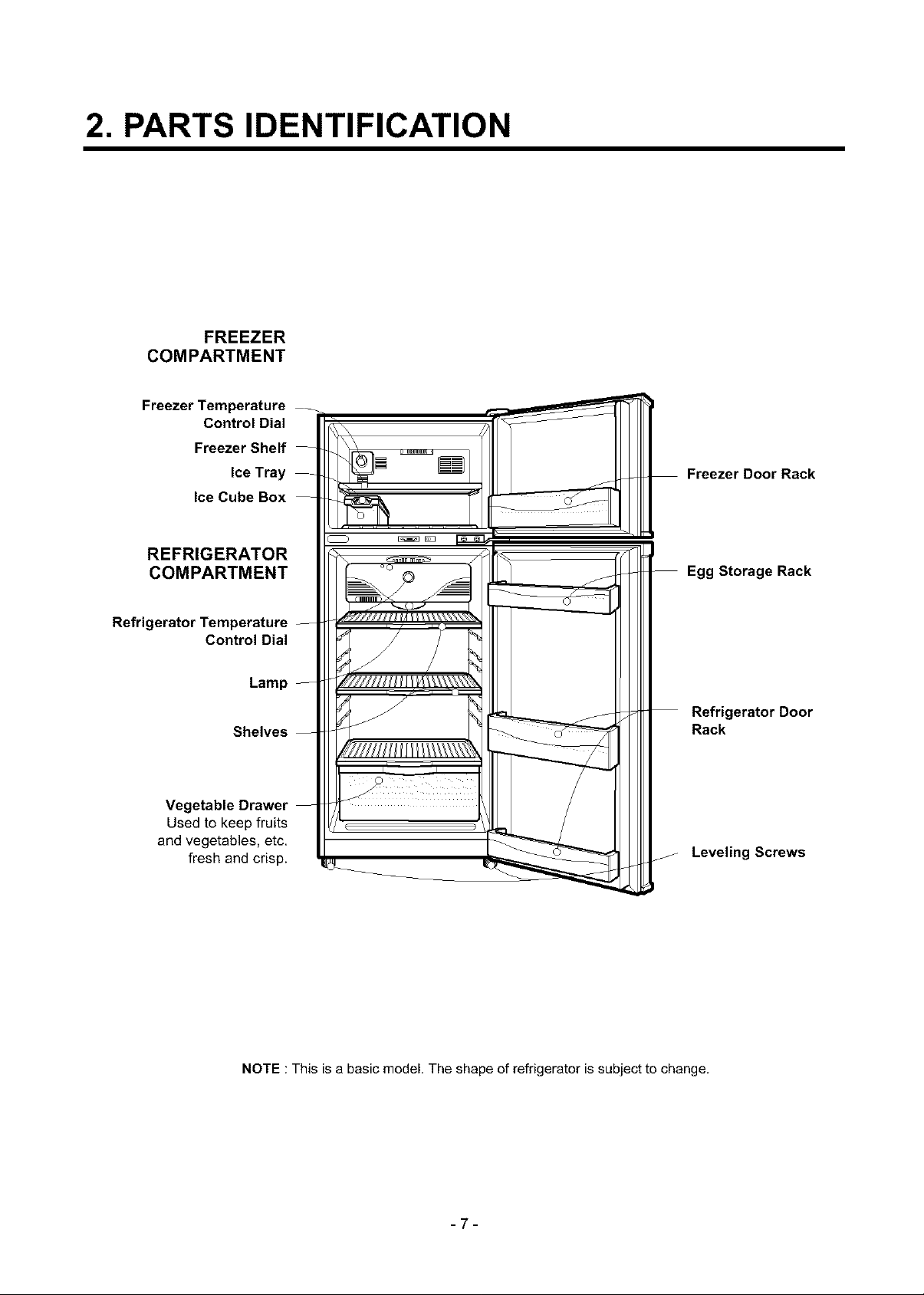
2. PARTS IDENTIFICATION
FREEZER
COMPARTMENT
Freezer Temperature
Control Dial
Freezer Shelf -
Ice Tray
Ice Cube Box
REFRIGERATOR
COMPARTMENT
Freezer Door Rack
-- Egg Storage Rack
Refrigerator Temperature --
Control Dial
Lamp --
Shelves --
Vegetable Drawer --
Used to keep fruits
and vegetables, etc.
fresh and crisp.
Refrigerator Door
Rack
Leveling Screws
NOTE : This is a basic model. The shape of refrigerator is subject to change.
-7-
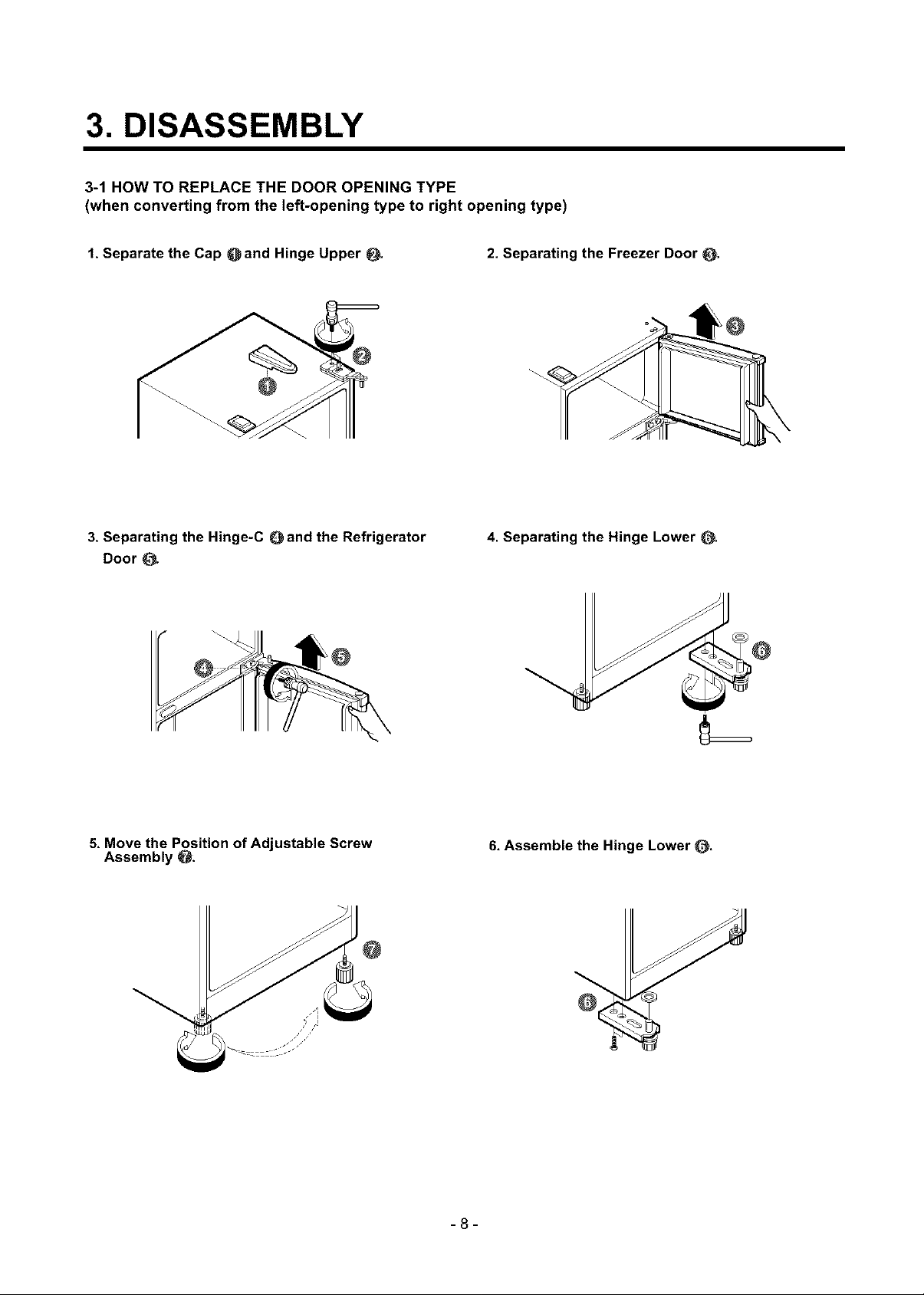
3. DISASSEMBLY
3-1 HOW TO REPLACE THE DOOR OPENING TYPE
(when converting from the left-opening type to right opening type)
1,Separate the Cap Oand Hinge Upper 2. Separating the Freezer Door _,
@
3, Separating the Hinge-C Oand the Refrigerator
Door
5, Move the Position of Adjustable Screw
Assembly O:
4. Separating the Hinge Lower
6, Assemble the Hinge Lower _.
-8-
 Loading...