

Page 1
ENGLISH
IMPORTANT!
Please read this instruction sheet completely before installing the product.
This air conditioning system meets strict safety and operating standards. As the installer or service person,
it is an important part of your job to install or service the system so it operates safely and efficiently.
CAUTION
: Improper installation, adjustment, alteration, service or maintenance can void the warranty.
The weight of the condensing unit requires caution and proper handling procedures when lifting
or moving to avoid personal injury. Use care to avoid contact with sharp or pointed edges.
Safety Precautions
• Always wear safety eye wear and work gloves when installing equipment.
• Never assume electrical power is disconnected. Check with meter and equipment.
• Keep hands out of fan areas when power is connected to equipment.
• R-410A causes frostbite burns.
• R-410A is toxic when burned.
NOTE TO INSTALLING DEALER: The Owners Instructions and Warranty are to be given to the owner
or prominently displayed near the indoor Furnace/Air Handler Unit.
P/No: 3828A22013X
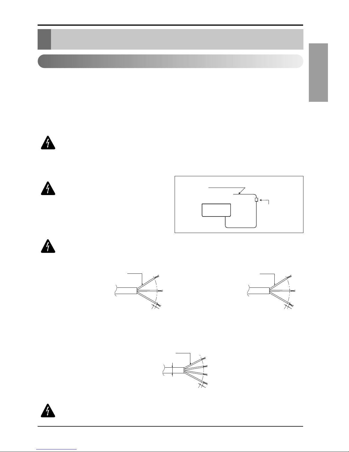
When wiring:
Electrical shock can cause severe personal injury or death. Only a qualified,
experienced electrician should attempt to wire this system.
• Do not supply power to the unit until all wiring and tubing are completed or reconnected and checked.
• Highly dangerous electrical voltages are used in this system. Carefully refer to the wiring diagram and these
instructions when wiring. Improper connections and inadequate grounding can cause accidental injury or death.
• Ground the unit following local electrical codes.
• Connect all wiring tightly. Loose wiring may cause overheating at connection points and a possible fire hazard.
When transporting:
Be careful when picking up and moving the indoor and outdoor units. Get a partner to help, and
bend your knees when lifting to reduce strain on your back. Sharp edges or thin aluminum fins on
the air conditioner can cut your finger.
When installing...
... in a wall: Make sure the wall is strong enough to hold the unit's weight.
It may be necessary to construct a strong wood or metal frame to provide added support.
... in a room: Properly insulate any tubing run inside a room to prevent "sweating" that can cause
dripping and water damage to wall and floors.
... in moist or uneven locatinons: Use a raised concrete pad or concrete blocks provide a solid,
level foundation for the outdoor unit. This prevents water damage and abnormal vibration.
... in an area with high winds: Securely anchor the outdoor unit down with bolts and a metal
frame. Provide a suitable air baffle.
... in a snowy area(for Heat Pump Model): Install the outdoor unit on a raised platform that is
higher than drifting snow. Provide snow vents.
When connecting refrigerant tubing
• Keep all tubing runs as short as possible.
• Use the flare method for connecting tubing.
• Check carefully for leaks before starting the test run.
When servicing
• Turn the power OFF at the main power box(mains) before opening the unit to check or repair
electrical parts and wiring.
• Keep your fingers and clothing away from any moving parts.
• Clean up the site after you finish, remembering to check that no metal scraps or bits of wiring have
been left inside the unit being serviced.
Special warnings
WARNING
• Installation or repairs made by unqualified persons can result in hazards to you and others.
Installation MUST conform with local building codes or, in the absence of local codes, with the National Electrical
Code NFPA 70/ANSI C1-1993 or current edition and Canadian Electrical Code Part1 CSA C.22.1.
• The information contained in the manual is intended for use by a qualified service technician familiar with safety
procedures and equipped with the proper tools and test instruments.
• Failure to carefully read and follow all instructions in this manual can result in equipment malfunction, property
damage, personal injury and/or death.
FLEX MULTI SPLIT DUAL ZONE
& TRI-ZONE INSTALLATION
INSTRUCTIONS
FRANÇAIS ESPAÑOL
Page 2

2 Room Air Conditioner
Room Air Conditioner Installation Manual
TABLE OF CONTENTS
Installation Parts Provided .........................................3
Safety Precautions......................................................4
Installation of Indoor, Outdoor Unit...........................7
Select the best location ...........................................7
Piping length and elevation......................................8
Fixing Installation Plate(Standart Type)....................9
Preparing work for Installation (Artcool Type Only)....
10
Sticking the installation guide map
and fixing Indoor unit (Artcool Type Only)..............11
Drill a hole in the wall.............................................11
Flaring Work and Connection of Piping..................12
Flaring work............................................................12
Connecting the Piping............................................13
Connecting the Cable between Indoor Unit
and Outdoor Unit.......................................................19
Connect the cable to the Indoor unit......................19
Connect the cable to the Outdoor unit...................20
Connection method of the connecting
cable(Example).......................................................21
Connect the cable to the indoor unit(For SE, S4
Chassis)..................................................................22
Checking the Drainage, Forming the Pipings and
Long Pipe Setting...................................................23
Checking the drainage............................................23
Forming the piping..................................................24
Air Purging and Evacuation.....................................25
Checking method....................................................25
Evacuation..............................................................26
Charging.....................................................................27
Panel Front Assembly (Artcool type Only).............28
Test Running..............................................................29
Combination indoor units ........................................30
Combination table of Models...................................31
❏ Level gauge
❏ Screw driver
❏ Electric dr ill
❏ Hole core drill (ø50mm)
❏ Horizontal meter
❏ Flaring tool set
❏ Specified torque wrenches
1.8kg.m, 4.2kg.m, 5.5kg.m, 6.6kg.m
(different depending on model No.)
❏ Spanner .................Half union
❏ A glass of water
❏ Screw driver
❏ Hexagonal wrench(4mm)
❏ Gas-leak detector
❏ Vacuum pump
❏ Gauge manifold
❏ Owner's manual
❏ Thermometer
❏ Holder Remote Control
Installation Requirements
Required T ools
Page 3
Installation Manual 3
ENGLISH
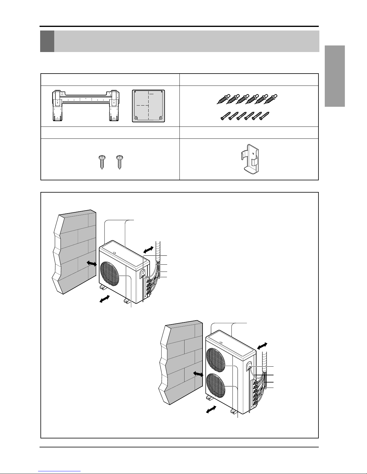
Installation Parts Provided
Installation Par ts Provided
Type "A" screws and plastic anchors
Type "B" screws
Holder Remote Control
Installation plate
Standard Type
more than
70cm
(27.6 inch)
more than
30cm
(11.8 inch)
more than
30cm
(11.8 inch)
Air Outlet
Air Intake
(side, rear)
Connection pipe
Drain hose
Connecting wire
Control cover
more than 30cm
(11.8 inch)
more than
70cm
(27.6 inch)
24k
36k
more than
20cm
(7.9 inch)
more than
20cm
(7.9 inch)
Air Outlet
Air Intake
(side, rear)
Connection pipe
Drain hose
Connecting wire
Control cover
more than 20cm
(7.9 inch)
Page 4

4 Room Air Conditioner
Do not use a defective or
underrated circuit breaker.
Use this appliance on a
dedicated circuit.
• There is risk of fire or electric
shock.
For electrical work, contact
the dealer, seller, a qualified
electrician, or an Authorized
Service Center.
• Do not disassemble or repair
the product.There is risk of
fire or electric shock.
Always ground the product.
• There is risk of fire or electric
shock.
Install the panel and the
cover of control box securely.
• There is risk of fire or electric
shock.
Always install a dedicated
circuit and breaker.
• Improper wiring or installation
may cause fire or electric
shock.
Use the correctly rated
breaker or fuse.
• There is risk of fire or electric
shock.
Safety Precautions
To prevent injury to the user or other people and property damage, the following instructions
must be followed.
■ Incorrect operation due to ignoring instruction will cause har m or damage. The seriousness
is classified by the following indications.
■ Meanings of symbols used in this manual are as shown below.
WARNING
CAUTION
This symbol indicates the possibility of death or serious injury.
This symbol indicates the possibility of injury or damage.
WARNING
Be sure not to do.
Be sure to follow the instruction.
Safety Precautions
■ Installation
Page 5
Installation Manual 5
ENGLISH
Safety Precautions
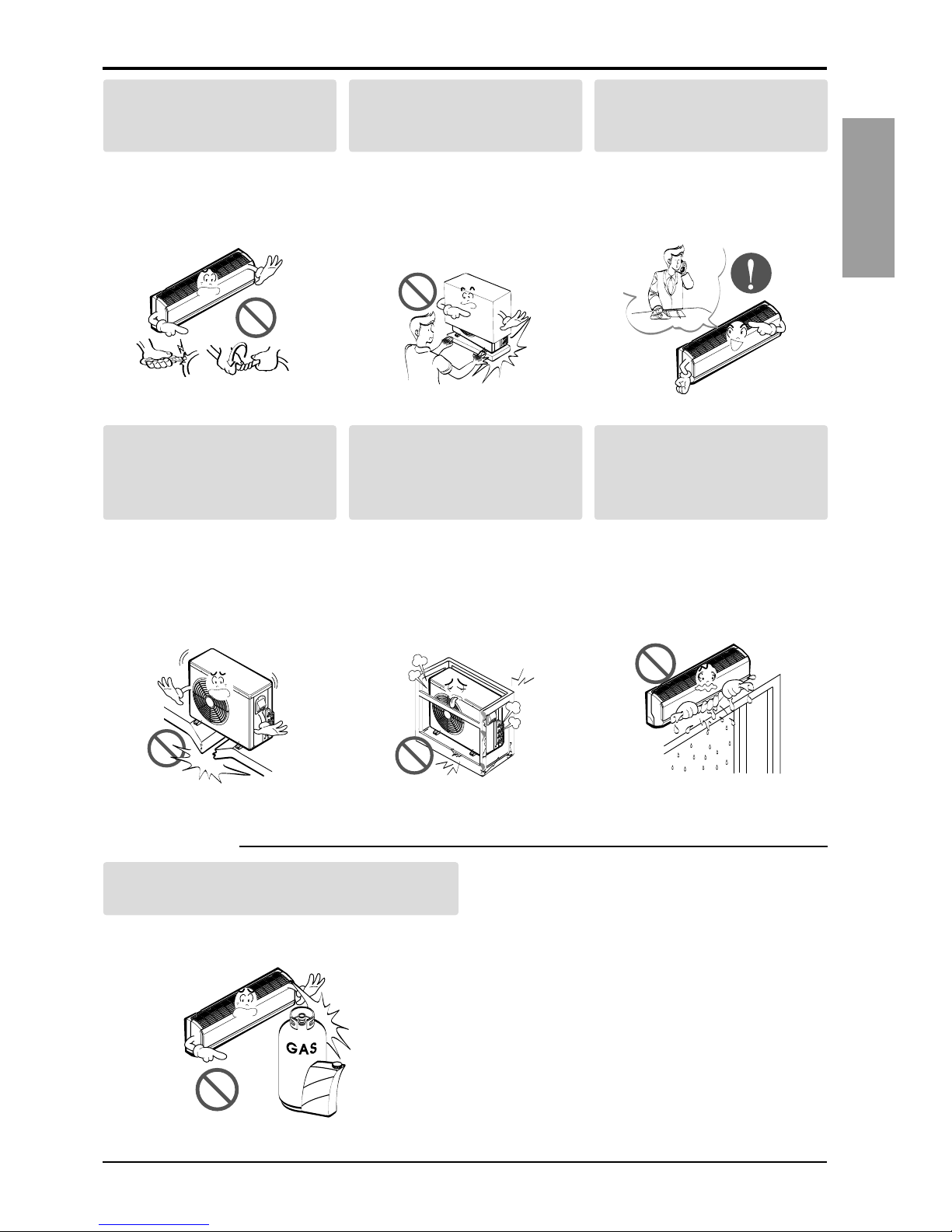
Do not store or use flammable gas or
combustibles near the product.
• There is risk of fire or failure of product.
Do not modify or extend the
power cable.
• There is risk of fire or electric
shock.
Be cautious when
unpacking and installing
the product.
•
Sharp edges could cause
injury. Be especially careful of
the case edges and the fins on
the condenser and evaporator.
For installation, always
contact the dealer or an
Authorized Service Center.
• There is risk of fire, electric
shock, explosion, or injury.
Do not install the product
on a defective installation
stand.
• It may cause injury, accident,
or damage to the product.
Be sure the installation area
does not deteriorate with
age.
•
If the base collapses, the air
conditioner could fall with it,
causing property damage, product
failure, and personal injury.
Do not let the air conditioner
run for a long time when the
humidity is very high and a
door or a window is left open.
• Moisture may condense and
wet or damage furniture.
■ Operation
Gasolin
Page 6
6 Room Air Conditioner
Safety Precautions
CAUTION
■ Installation
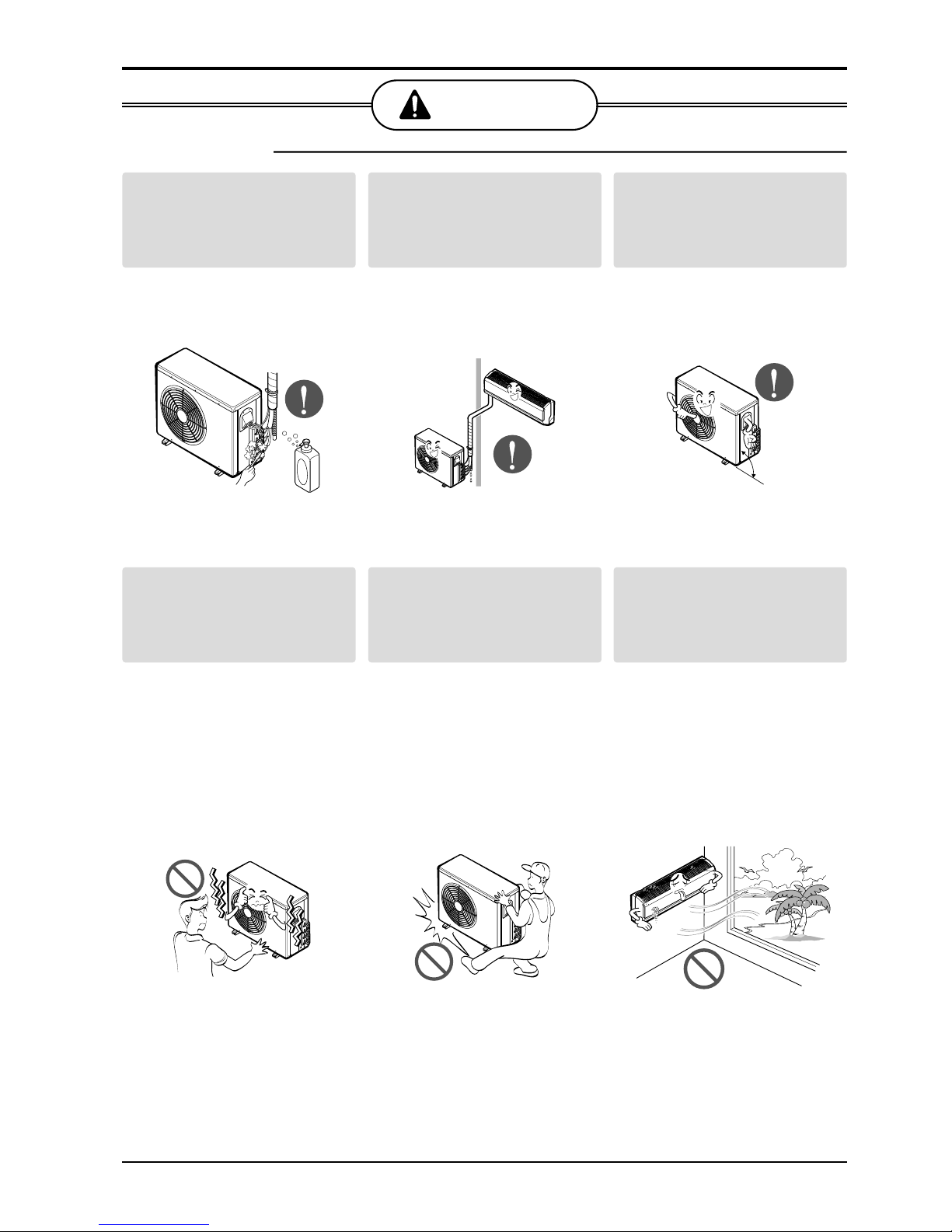
Always check for gas
(refrigerant) leakage after
installation or repair of
product.
• Low refrigerant levels may
cause failure of product.
Install the drain hose to
ensure that water is drained
away properly.
• A bad connection may cause
water leakage.
Keep level even when
installing the product.
• To avoid vibration or water
leakage.
Do not install the product
where the sound or hot air
from the outdoor unit could
be offensive to neighbors.
• It may cause a problem for
your neighbors.
Use two or more people to
lift and transport the
product.
• Avoid personal injury.
Do not install the product
where it will be exposed to
salt spray directly.
• It may cause corrosion on the
product. Corrosion,
particularly on the condenser
and evaporator fins, could
cause product malfunction or
inefficient operation.
90°
Page 7
Installation Manual 7
ENGLISH
Installation of Indoor, Outdoor Unit
Installation of Indoor, Outdoor Unit
Read completely, then follow step by step.
Indoor unit
1. Do not have any heat or steam near the unit.
2. Select a place where there are no obstacles
in front of the unit.
3. Make sure that condensation drainage can be
conveniently routed away.
4. Do not install near a doorway.
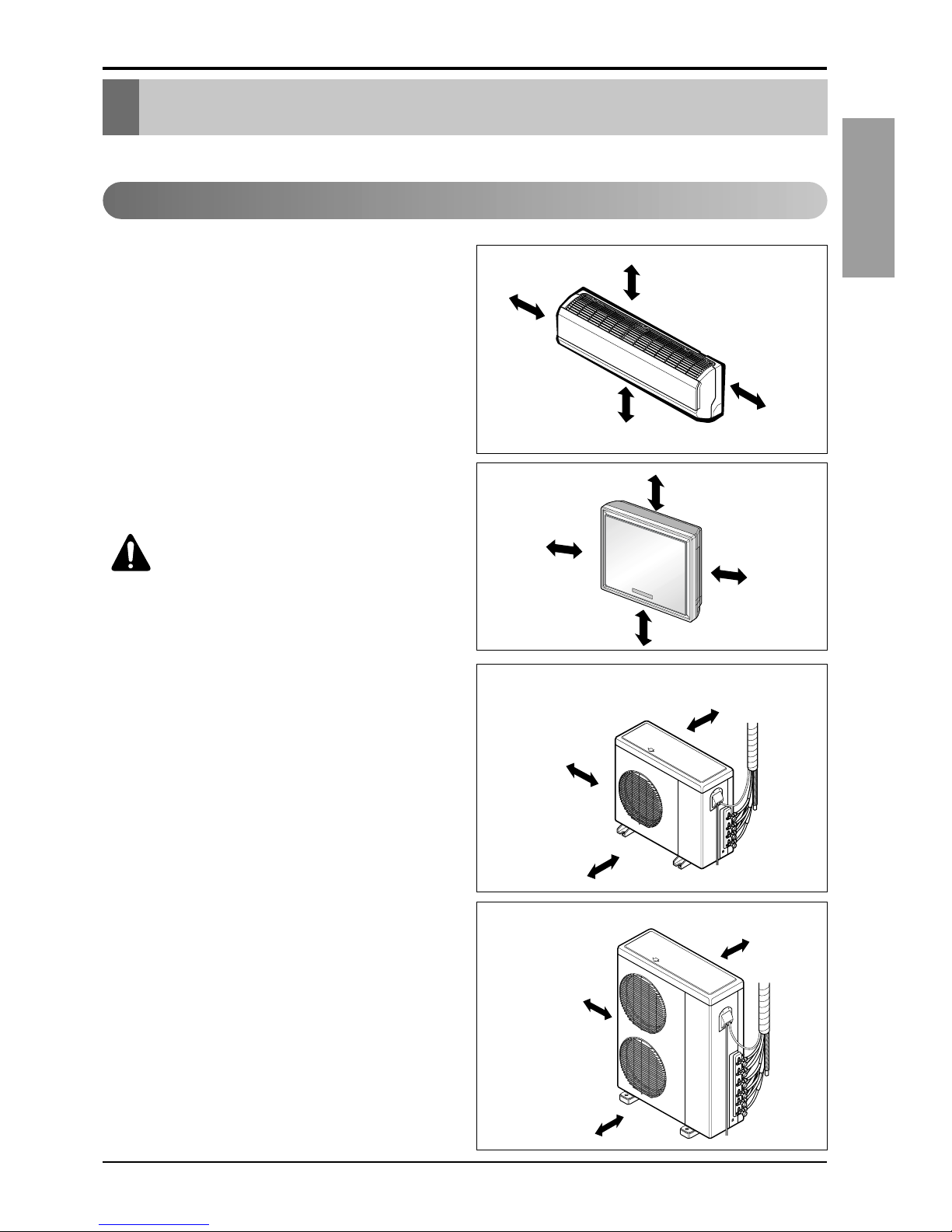
5. Ensure the spaces indicated by arrows from
the wall, ceiling, fence or other obstacles.
6. Use a stud finder to locate studs to prevent
unnecessary damage to the wall.
Outdoor unit
1. If an awning is built over the unit to prevent
direct sunlight or rain exposure, make sure
that heat radiation from the condenser is not
restricted.
2. Ensure that the spaces indicated by arrows
around front, back and side of the unit.
3. Do not place animals and plants in the path
of the warm air.
4.Take the air conditioner weight into account
and select a place where noise and vibration
are minimum.
5.
Select a place so that the warm air and sound
from the air conditioner do not disturb
neighbors.
Rooftop Installations:
If the outdoor unit is installed on a roof
structure, be sure to level the unit.Ensure the
roof structure and anchoring method are
adequate for the unit location. Consult local
codes regarding rooftop mounting.
Select the best location
More than 5cm
(2.0 inch)
More than 5cm
(2.0 inch)
More than 2.3m
(90.6 inch)
More than 5cm
(2.0 inch)
More than 10cm
More than 50cm
More than 2m
More than 50cm
more than 70cm
(27.6 inch)
more than 30cm
(11.8 inch)
more than 30cm
(11.8 inch)
more than 70cm
(27.6 inch)
more than 20cm
(7.9 inch)
more than 20cm
(7.9 inch)
CAUTION: Install the indoor unit
on the wall where the height from
the floors more than 2.3m(7.5ft).
24k
36k
Page 8
8 Room Air Conditioner
Installation of Indoor, Outdoor Unit
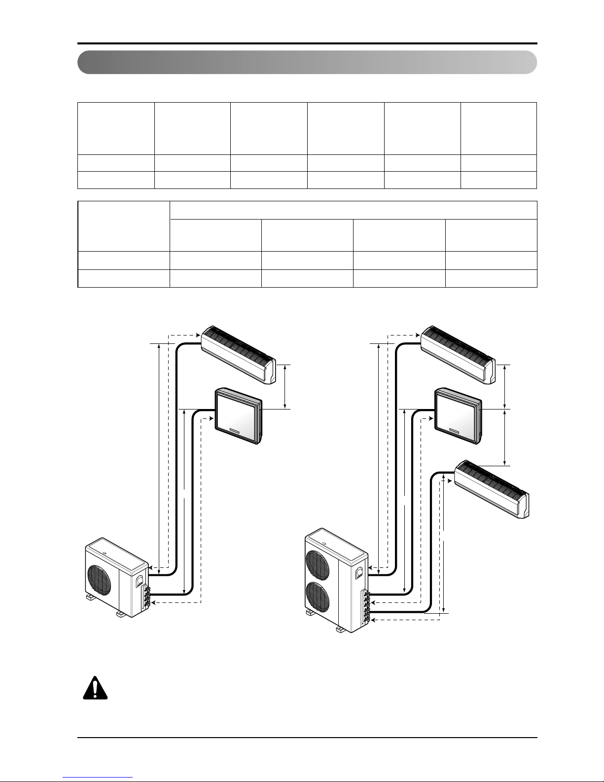
Multi Piping Type
Piping length and elevation
24k 30m(100ft) 15m(50ft) 3m(10ft) 7.5m(25ft) 7.5m(25ft)
36k 45m(150ft) 15m(50ft) 3m(10ft) 7.5m(25ft) 7.5m(25ft)
Capacity(Btu/h)
Max total length
of all pipes
(A+B/A+B+C)
Max length of
each pipe
(A/B/C)
Min length of
each pipe
(A/B/C)
Max Elevation
between each
indoor unit and
outdoor unit (h1)
Max elevation
between indoor
units (h2)
h2
h2
h1
A
B
B
C
h2
h1
A
B
h1
h1
h1
CAUTION: Capacity is based on standard length and maximum allowance
length is on the basis of reliability. Oil trap should be installed every 5~7
meters (16.4~23.0ft).
9K 3/8" 1/4" 7.5m(25ft) 20g/m(0.32oz/ft)
12K 3/8" 1/4" 7.5m(25ft) 20g/m(0.32oz/ft)
Gas Liquid Standard Length
Additional
Refrigerant
Indoor Capacity
(Btu/h)
Pipe Size
24k
36k
Page 9
ENGLISH
Installation Manual 9
Installation of Indoor, Outdoor Unit
The wall you select should be strong and solid
enough to prevent vibration
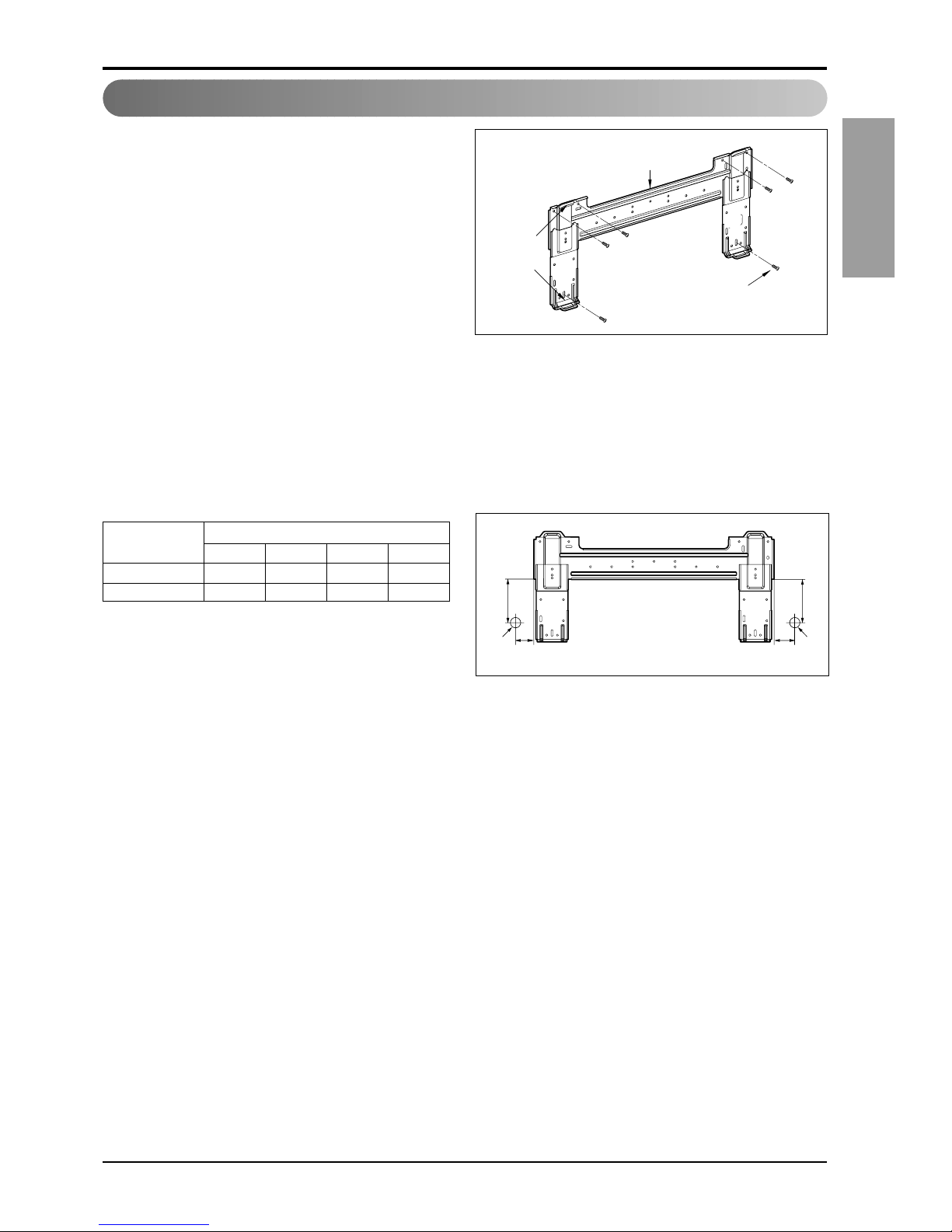
1. Mount the installation plate on the wall with
type "A" screws.If mounting the unit on a
concrete wall, use anchor bolts.
• Mount the installation plate horizontally by
aligning the centerline using a level.
2. Measure the wall and mark the centerline. It
is also important to use caution concer ning
the location of the installation plate-routing
of the wiring to power outlets is through the
walls typically. Drilling the hole through the
wall for piping connections must be done
safely.
Fixing Installation Plate(Standart Type)
Installation Plate
Type "A" screw
Chassis
Hook
Installation plate
Left rear piping Right rear piping
Ø70mm
Ø70mm
D
B
A
C
ABCD
S4 50 105 59 105
SE 65 110 85 110
CHASSIS
(Grade)
Distance (mm)
Page 10
10 Room Air Conditioner
Installation of Indoor, Outdoor Unit
Preparing work for Installation (Artcool Type Only)
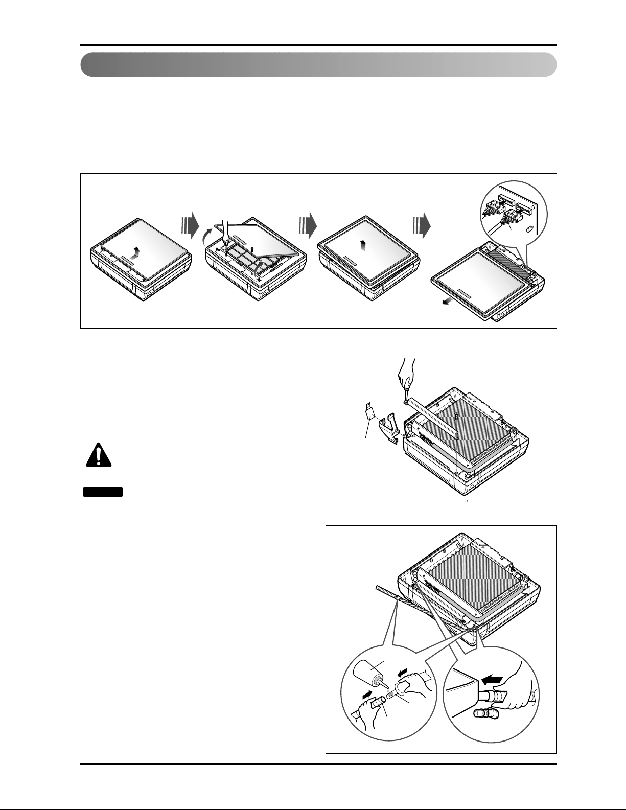
Open panel front
1. First, push the front panel backward and lift it up to remove the two screws.
2.The moment of lifting the both lower parts of panel front, you can hear sound this panel came
out, In this time panel front is separated
3. After pull down this panel a bit, and separate connecting wire with product.
Remove cover pipe and cover side
1. Remove two screws(for fixing cover pipe)
2. Pull up the cover side of desired connecting
direction, then cover side is separated.
3. In case of connecting direction is left or right,
path through the hole of cover side.
CAUTION: After removing the pipe
hole, cut the burr for safety.
When connecting pipe path through rear
wall, don’t remove the hole.
NOTICE
Drain hose junction
1. Remove the rubber stopple of desired
direction of drainage.
2. As the following picture, Insert drain hose in
the handle of drain pan, and join drain hose
and connecting hose.
Panel Front
Connector
Pipe hole
rubber cap
Only one
desiring direction
Connecting
part
Adhesive
Drain
hose
Page 11
Installation Manual 11
ENGLISH
Installation of Indoor, Outdoor Unit
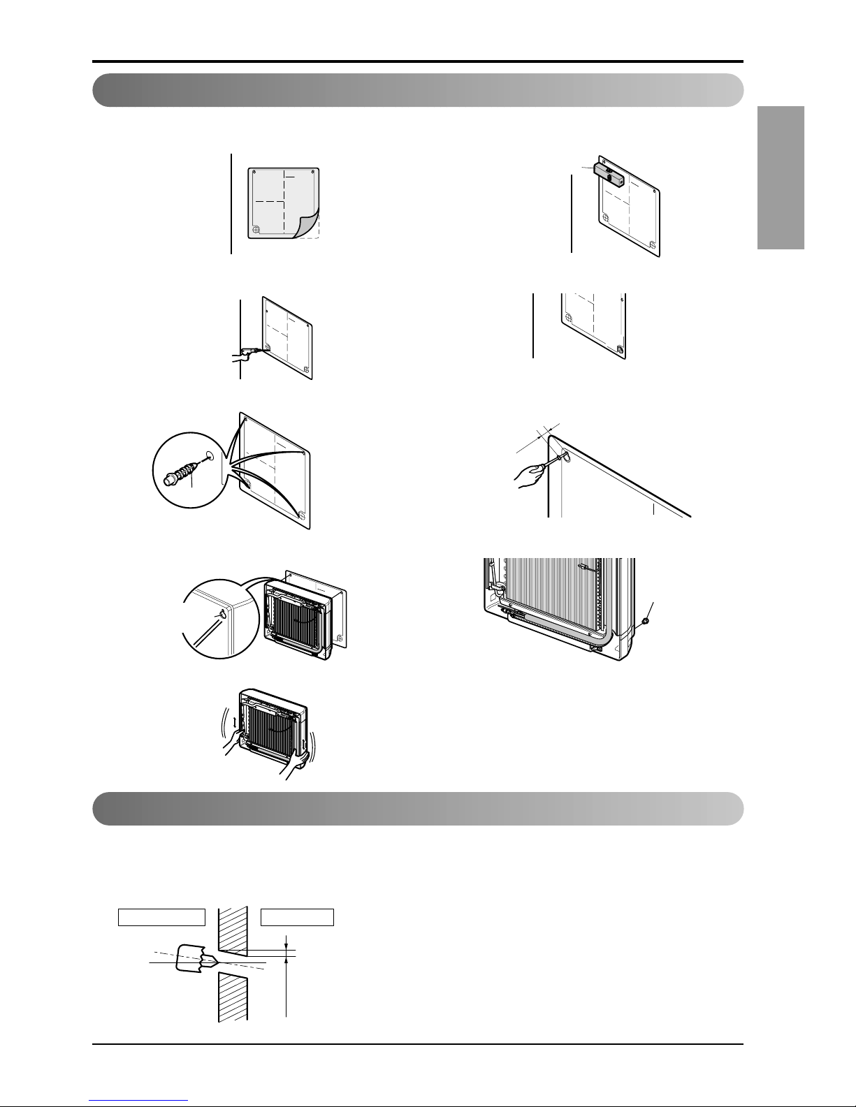
• Drill the piping hole with a ø70mm hole core drill. Dr ill the piping hole at either the right or the
left with the hole slightly slanted to the outdoor side.
Drill a hole in the wall
5-7mm
(0.2"~0.3")
Indoor
WALL
Outdoor
Sticking the installation guide map and fixing Indoor unit (Artcool Type Only)
Plastic anchors
INSTALLA TION GUIDE MAP
1
0
m
m
INSTALLATION GU
IN
S
T
A
IIA
T
IO
N
G
U
ID
E
M
A
P
Put an Installation Guide Map on the desired surface.
Make a hole with diameter of 6mm and depth of
30-35mm when piercing a screw point.
Drive the fore plastic anchors into drilled points.
Hang the hole of product at the upper screws.
(In this time, Remove the map)
(Falling attention)
Check the fixed product with light power.
Adjust level even by level guage and fix to installation
for reference on the well.
Drill the piercing part for connecting pipe as diameter
50mm. (In case of piercing rear surface)
Refer to No. 5 on this page when making a hole in the wall.
First, Drive the two points of the upper parts by screws
(Leave 10mm for hanging product)
Drive the lower parts after facing the hole of product
with plastic anchors, and fix completely the upper
screws.
In case of nothing wrong in the matter, connect the pipe
and the wire. (Installation manual reference)
Horizontality
IN
S
T
A
L
L
A
TIO
N
G
U
ID
E
M
A
P
Plastic anchors
INSTALLA TION GUIDE MAP
IN
S
T
A
L
L
A
T
IO
N
G
U
ID
E
M
A
P
Hanger hole
(Rear side of
product)
Page 12
12 Room Air Conditioner
Flaring Work and Connection of Piping
Flaring Work and Connection of Piping
Flaring work
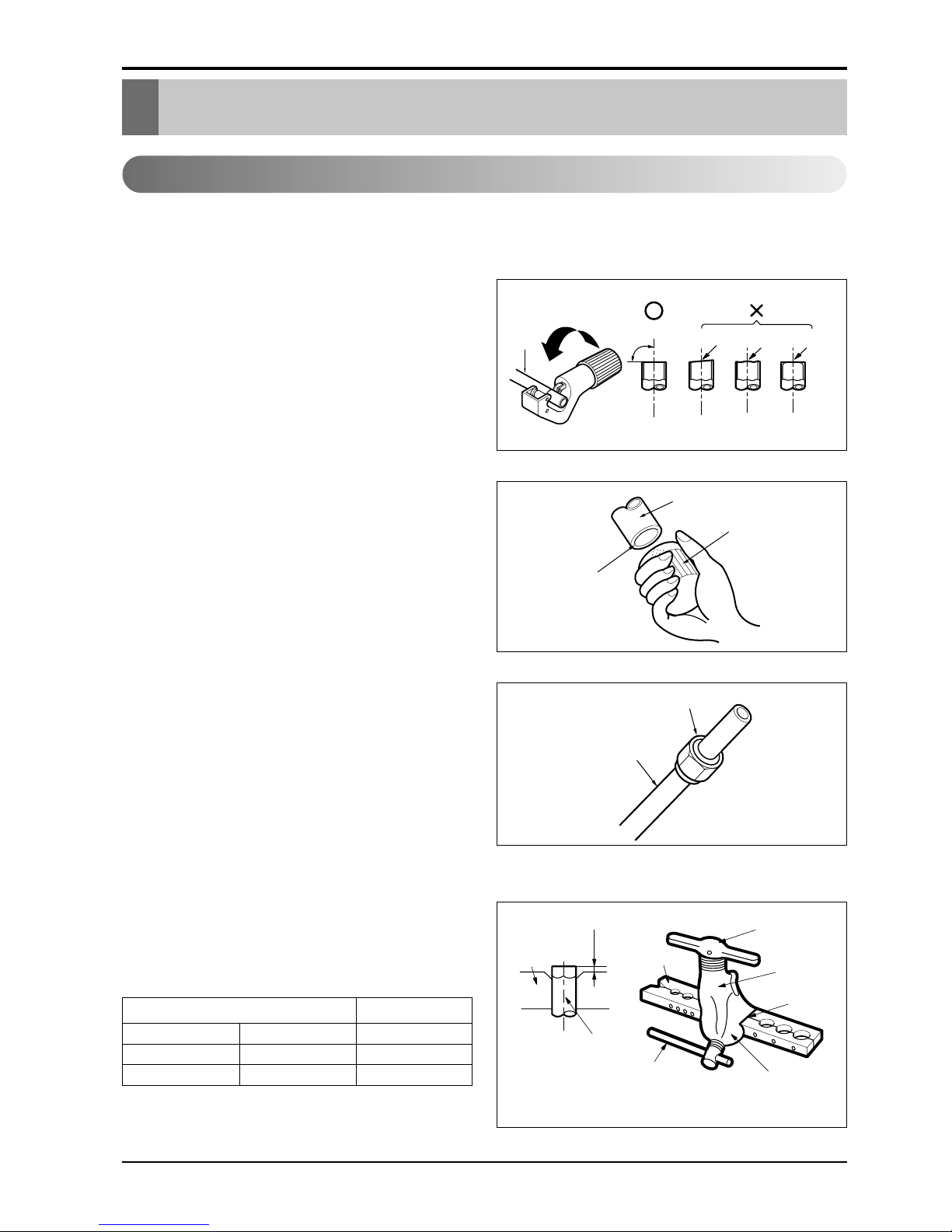
Main cause for gas leakage is due to defect in flaring work. Carry out correct flaring work in the
following procedure.
Cut the pipes and the cable.
1. Use the piping kit accessory or the pipes
purchased locally.
2. Measure the distance between the indoor and
the outdoor unit.
3. Cut the pipes a little longer than measured
distance.
4. Cut the cable 1.5m (5.0ft) longer than the pipe
length.
Burrs removal
1. Completely remove all burrs from the cut cross
section of pipe/tube.
2. Put the end of the copper tube/pipe in a
downward direction as you remove burrs in
order to avoid dropping burrs into the tubing.
Putting nut on
• Remove flare nuts attached to indoor and
outdoor unit, then put them on pipe/tube having
completed burr removal.
(not possible to put them on after flaring work)
Flaring work
• Carry out flaring work using flaring tool as shown
below.
• Firmly hold copper pipe in a die in the dimension
shown in the table above.
Copper
pipe
90°
Slanted Uneven Rough
Pipe
Reamer
Point down
Flare nut
Copper tube
mm inch mm
Ø6.35 1/4 0~0.5
Ø9.52 3/8 0~0.5
Outside diameter A
Bar
Copper pipe
Clamp handle
Red arrow mark
Cone
Yoke
Handle
Bar
"A"
Page 13
Installation Manual 13
ENGLISH
Flaring Work and Connection of Piping
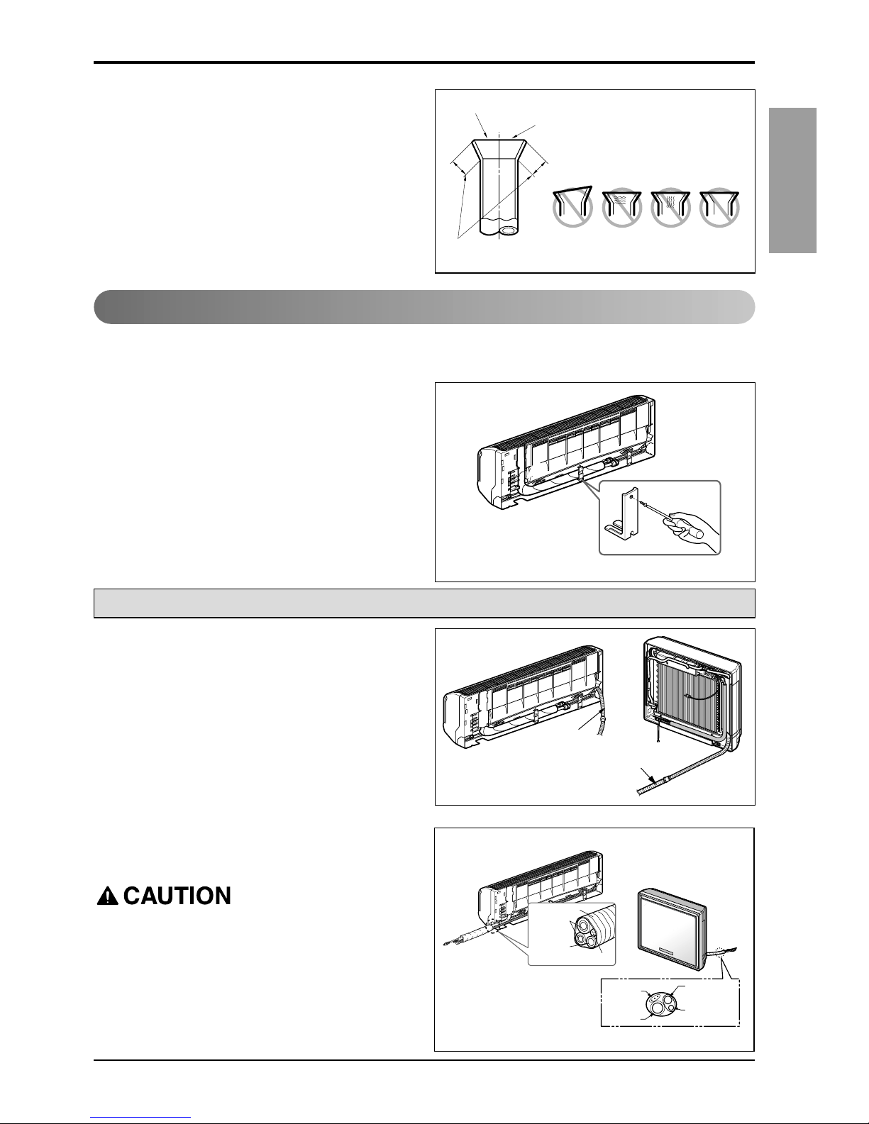
Check
1. Compare the flared work with the figure by.
2. If a flared section is defective, cut it off and
do flaring work again.
Indoor
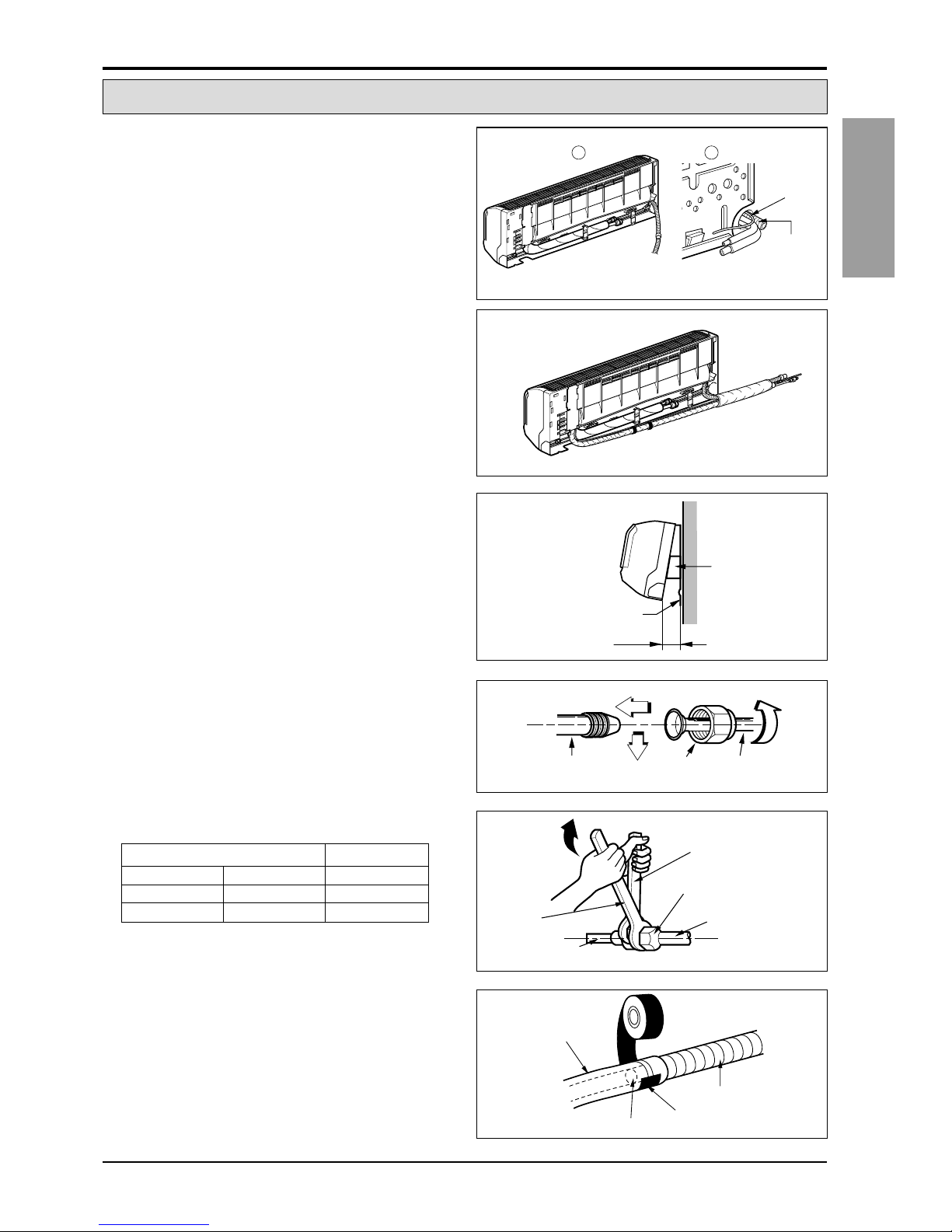
1. Prepare the indoor unit's piping and drain hose for installation through the wall.
2. Remove the plastic tubing retainer(see the
illustration by) and pull the tubing and drain
hose away from chassis.
3. Replace only the plastic tubing holder 1, not
the holder 2 in the original position.
1. Route the indoor tubing and the drain hose in
the direction of rear right.
2.
Insert the connecting cable into the indoor unit
from the outdoor unit through the piping hole.
• Do not connect the cable to the indoor unit.
• Make a small loop with the cable for easy
connection later.
3.Tape the tubing, drain hose, and the
connecting cable.Be sure that the drain hose
is located at the lowest side of the bundle.
Locating at the uper side can cause drain pan
to overflow inside the unit.
If the drain hose is routed inside the room,
insulate the hose with an insulation material*
so that dripping from "sweating"(condensation)
will not damage furniture or floors.
*Foamed polyethylene or equivalent is
recommended.
Inclined
Inside is shiny without scratches
Smooth all round
Even length
all round
Surface
damaged
Cracked Uneven
thickness
= Improper flaring =
Connecting the Piping
For right rear piping
Drain hose
Drain hose
Connecting
pipe
Connecting cable
Tape
Drain hose
Connecting
cable
Gas side piping
Liquid side piping
Drain hose
Loop
Page 14
14 Room Air Conditioner
Flaring Work and Connection of Piping
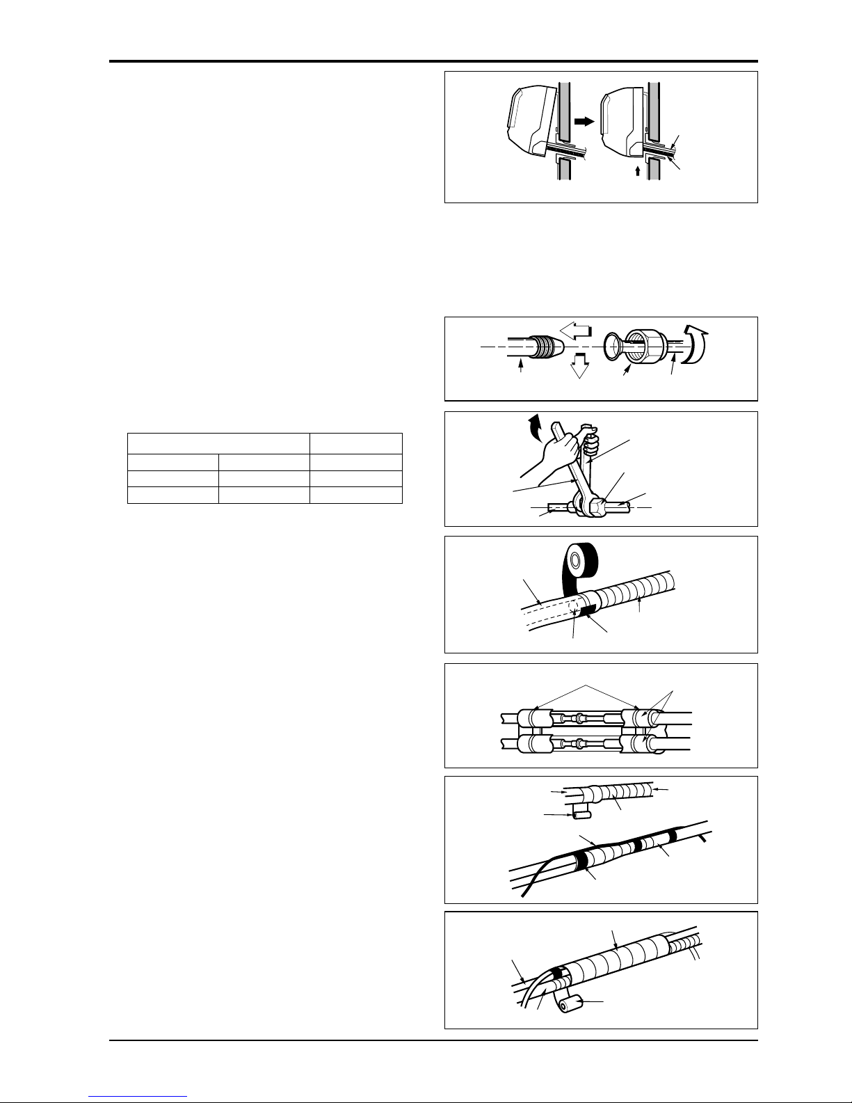
4. Indoor unit installation
Hook the indoor unit onto the upper portion of
the installation plate.(Engage the two hooks
of the rear top of the indoor unit with the
upper edge of the installation plate.) Ensure
that the hooks are properly seated on the
installation plate by moving it left and right.
Press the lower left and right sides of the unit
against the installation plate until the hooks
engage into their slots(clicking sound).
Connecting the piping to the indoor unit and
drain hose to drain pipe.
1. Align the center of the pipes and sufficiently
tighten the flare nut by hand.
2.Tighten the flare nut with a wrench.
3.When extending the drain hose at the indoor
unit, install the drain pipe.
Wrap the insulation material around the
connecting portion.
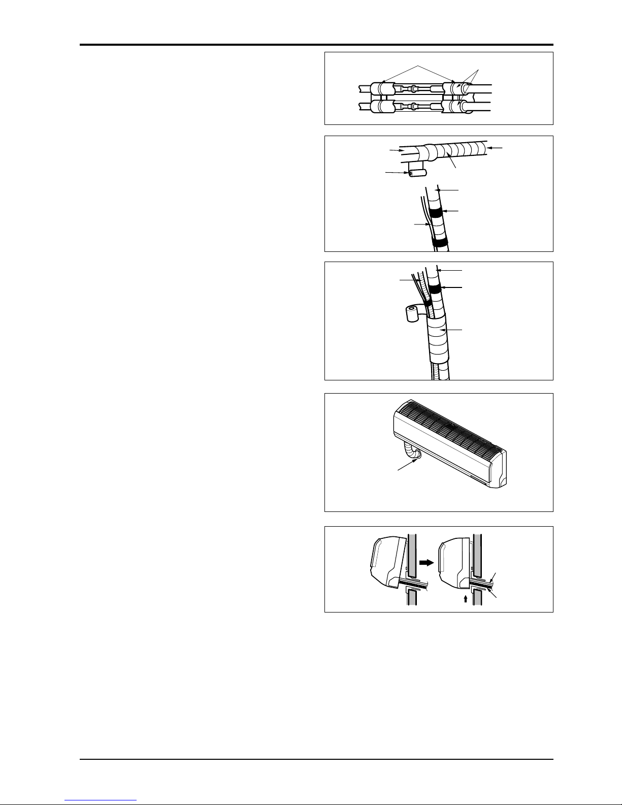
1. Overlap the connection pipe insulation
material and the indoor unit pipe insulation
material. Bind them together with vinyl tape
so that there may be no gap.
2.Wrap the area which accommodates the rear
piping housing section with vinyl tape.
3. Bundle the piping and drain hose together by
wrapping them with vinyl tape for enough to
cover where they fit into the rear piping
housing section.
Drain hose
Connecting
cable
Indoor unit tubing Flare nut Pipes
Wrench
Indoor unit tubing
Open-end wrench (fixed)
Connection pipe
Flare nut
Vinyl tape(narrow)
Adhesive
Drain pipe
Indoor unit drain hose
Plastic bands
Insulation material
Vinyl tape(narrow)
Connection pipe
Connecting cable
Vinyl tape (wide)
Wrap with vinyl tape
Indoor unit pipe
Pipe
Wrap with vinyl tape
Drain hose
Pipe
Vinyl tape(wide)
mm inch kg.m
Ø6.35 1/4 1.8
Ø9.52 3/8 4.2
Outside diameter Torque
Page 15
Installation Manual 15
ENGLISH
Flaring Work and Connection of Piping
1. Route the indoor tubing and the drain hose to
the required piping hole position.
2. Inser t the piping, drain hose, and the
connecting cable into the piping hole.
3.
Insert the connecting cable into the indoor unit.
• Don't connect the cable to the indoor unit.
• Make a small loop with the cable for easy
connection later.
4.Tape the drain hose and the connecting
cables.
5. Indoor unit installation
• Hang the indoor unit from the hooks at the
top of the installation plate.
• Insert the spacer etc. between the indoor
unit and the installation plate and separate
the bottom of the indoor unit from the wall.
Connecting the piping to the indoor unit and
the drain hose to drain pipe.
1. Align the center of the pipes and sufficiently
tighten the flare nut by hand.
2.Tighten the flare nut with a wrench.
3.When extending the drain hose at the indoor
unit, install the drain pipe.
For left rear piping
Drain pipe
Connecting
cable
1 2
Installation plate
Spacer
Indoor unit
8cm
Indoor unit tubing Flare nut Pipes
Wrench
Indoor unit tubing
Connection pipe
Flare nut
Open-end wrench (fixed)
Vinyl tape
Adhesive
Drain hose
Indoor unit drain hose
(narrow)
mm inch kg.m
Ø6.35 1/4 1.8
Ø9.52 3/8 4.2
Outside diameter Torque
Page 16
16 Room Air Conditioner
Flaring Work and Connection of Piping
Wrap the insulation material around the
connecting portion.
1. Overlap the connection pipe heat insulation
and the indoor unit pipe heat insulation
material. Bind them together with vinyl tape
so that there may be no gap.
2.Wrap the area which accommodates the rear
piping housing section with vinyl tape.
3. Bundle the piping and drain hose together by
wrapping them with cloth tape over the range
within which they fit into the rear piping
housing section.
Reroute the pipings and the drain hose
across the back of the chassis.
Indoor unit installation
1. Remove the spacer.
2. Ensure that the hooks are properly seated on
the installation plate by moving it left and
right.
3. Press the lower left and right sides of the unit
against the installation plate until the hooks
engage into their slots(clicking sound).
Plastic bands
Insulation material
Vinyl tape(narrow)
Connection
pipe
Connecting cable
Indoor
unit piping
Pipe
Vinyl tape
(wide)
Wrap with vinyl tape
Drain hose
Vinyl tape(narrow)
Pipe
Wrap with
vinyl tape(wide)
Piping for
passage through
piping hole
Drain hose
Connecting
cable
Page 17
Installation Manual 17
ENGLISH
Flaring Work and Connection of Piping
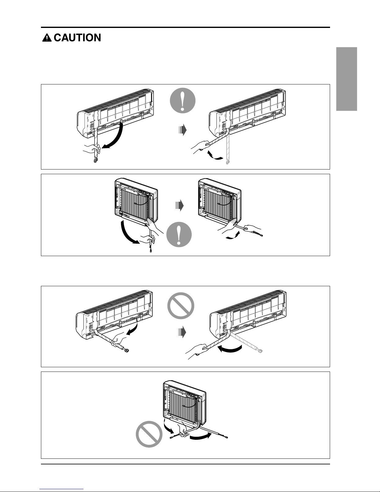
Installation Information. For left piping. Follow the instruction below.
Good case
• Press on the upper side of clamp and unfold the tubing to downward slowly.
Bad case
• Following bending type from right to left may cause damage to the tubing.
Page 18
18 Room Air Conditioner
Flaring Work and Connection of Piping
Outdoor
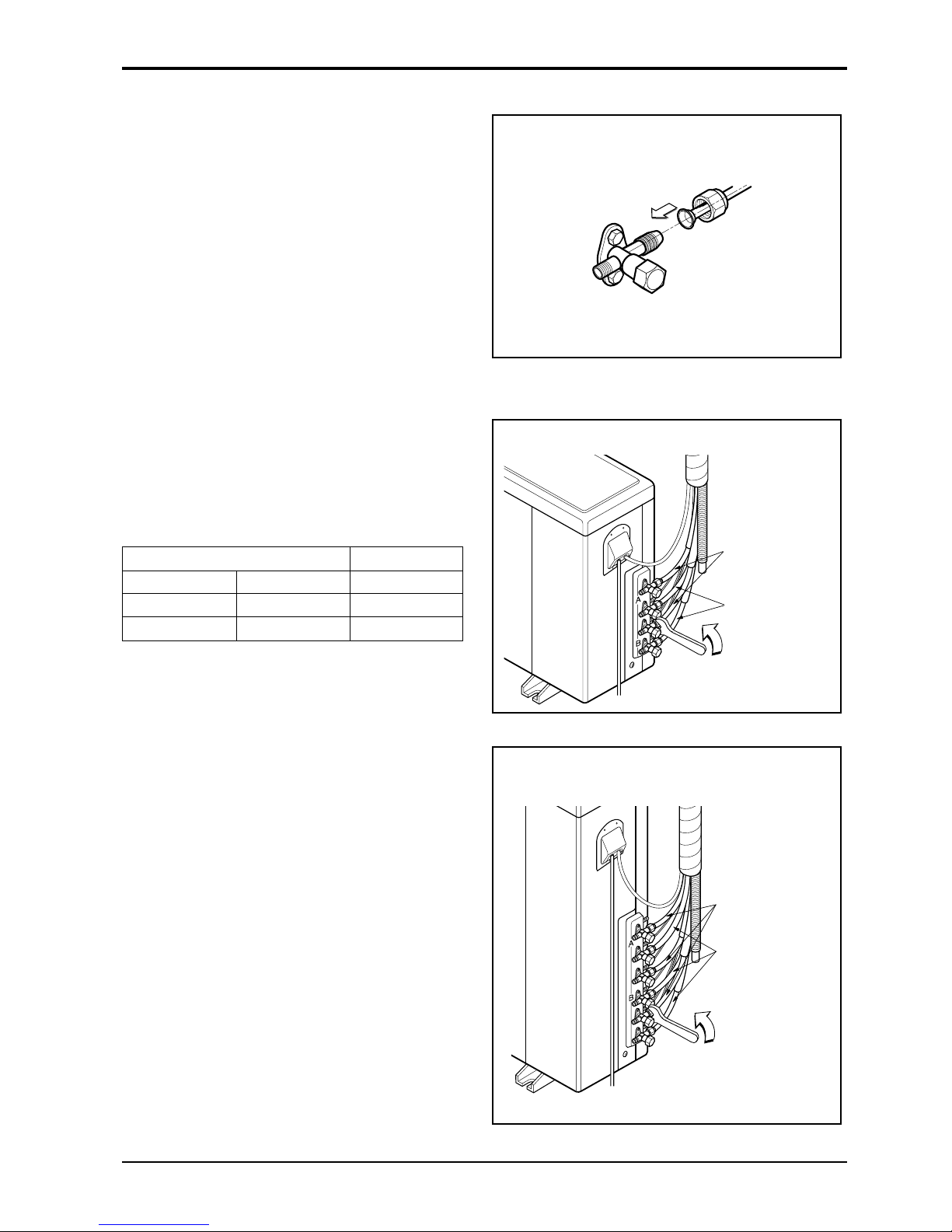
Align the center of the pipings and sufficiently
tighten the flare nut by hand.
Finally, tighten the flare nut with torque wrench
until the wrench clicks.
• When tightening the flare nut with torque
wrench, ensure the direction for tightening
follows the arrow on the wrench.
Outdoor unit
36k
Liquid side piping
Torque wrench
B-UNIT
A-UNIT
Gas side piping
Torque wrench
Liquid side piping
B-UNIT
C-UNIT
A-UNIT
Gas side piping
Outdoor unit
24k
Outside diameter Torque
mm inch kg.m
Ø6.35 1/4 1.8
Ø9.52 3/8 4.2
Page 19
Installation Manual 19
ENGLISH
Connecting the Cable between Indoor Unit and Outdoor Unit
Connecting the Cable between Indoor Unit and Outdoor Unit
Connect the cable to the indoor unit by connecting the wires to the terminals on the control
board individually according to the outdoor unit connection. (Ensure that the color of the wires
of the outdoor unit and the terminal No. are the same as those of the indoor unit.)
The earth wire should be longer than the common wires.
The circuit diagram is not subject to change without notice.
When installing, refer to the electrical diagram behind the front panel of Indoor Unit.
The wiring for the outdoor unit can be found on the inside of the Outdoor Unit control cover.
Connect the cable to the Indoor unit.
RECOMMAND:
• The circuit diagram is not subject to change without notice.
• Be sure to connect wires according to the wiring diagram.
• Connect the wires firmly, so that not to be pulled out easily.
• Connect the wires according to color codes by referring to the wiring diagram.
RECOMMAND: Provide a circuit
breaker between power source
and the outdoor unit as shown
below.
RECOMMAND:
The power cord connected to the outdoor unit should be
complied with the following specifications (ETL recognized and CSA certified).
The power connecting cable connected to the indoor and outdoor unit
should be complied with the following specifications
(ETL recognized and
CSA certified).
Air
Conditioner
Main power source
Circuit Breaker
Use a circuit breaker
or time delay fuse.
G
N
/Y
L
2
0
m
m
Line voltage (208~230V)
24K 36K
G
N
/Y
L
2
0
m
m
Line voltage (208~230V)
AWG14
AWG12
G
N
/Y
L
2
0
m
m
AWG18
Low voltage (below 40V)
RECOMMAND:
When using the separate wire as the power cord, please fix the
separate wire into the control box panel by using tie wrap as the fixture.
Page 20
20 Room Air Conditioner
Connecting the Cable between Indoor Unit and Outdoor Unit
Connect the cable to the Outdoor unit.
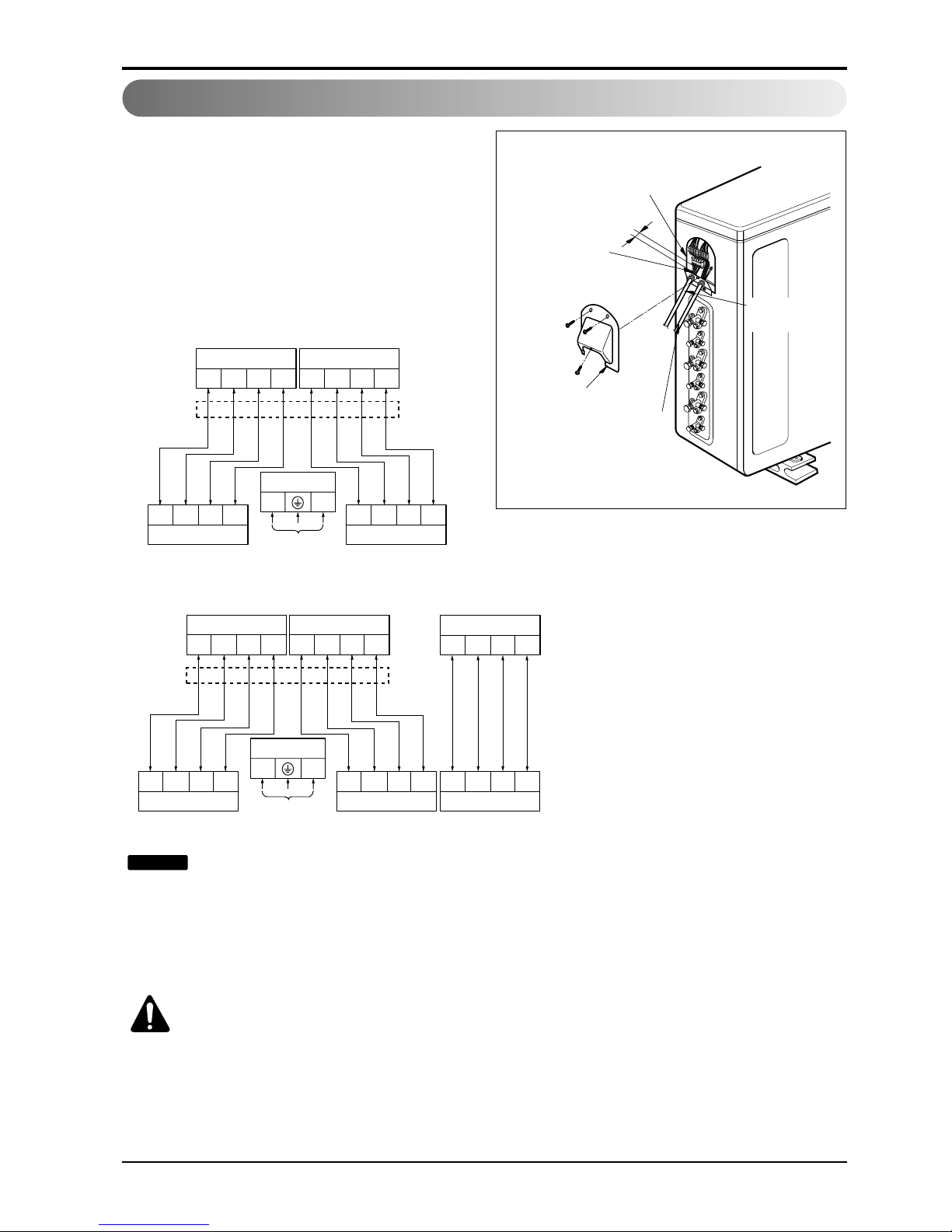
1. Remove the cover control from the unit by
loosening the screw.
Connect the wires to the terminals on the
control board individually as the following.
2. Secure the cable onto the control board with
the holder (clamper).
3. Refix the cover control to the original position
with the screw.
:
1. Separately wire the high and low voltage line.
2. Use heat-proof electrical wiring capable of withstanding temperature up to 75°C(167°F).
3. Use outdoor and waterproof connection cable rated more than 300V for the connection between
indoor and outdoor unit. (For example, Type SJO-WA)
WARNING:
• Be sure to comply with local codes while running the wire from the indoor unit to
the outdoor unit(size of wire and wiring method, etc).
• Every wire must be connected firmly.
• No wire should be allowed to touch refrigerant tubing, the compressor or any
moving parts.
NOTICE
Outdoor unit
Over 5mm
Holder for
power supply
cord
Connecting
cable
Cover control
Terminal block
Power supply
cable
A-UNIT
4321
B-UNIT
4321
Terminal BLOCK
4321
Terminal BLOCK
4321
LN
Power Source
208/230V AC
(High voltage)
Indoor A-UNIT
24k Outdoor side
Indoor B-UNIT
Connecting cable(Low voltage)Connecting cable(Low voltage)
Connecting cable(Low voltage)
A-UNIT
4321
B-UNIT
4321
Terminal BLOCK
4321
Terminal BLOCK
4321
LN
Power Source
208/230V AC
(High voltage)
Indoor A-UNIT
36k Outdoor side
Indoor B-UNIT
C-UNIT
4321
Terminal BLOCK
4321
Indoor C-UNIT
Connecting cable(Low voltage)Connecting cable(Low voltage)
Page 21
Installation Manual 21
ENGLISH
Connecting the Cable between Indoor Unit and Outdoor Unit
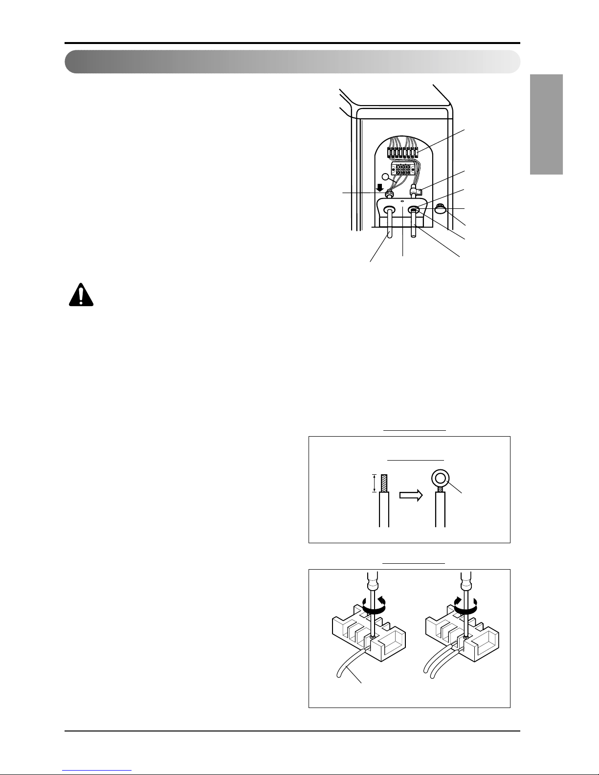
(1) Remove two-caps on the conduit panel.
(2) Make a hole appropriate for the passage of
connection cable through on cap by tool.
(for low voltage line)
(3) Pass the connecting cable through the hole.
(4) Properly connect the cable on the terminal block.
(5) Fix the connection cable with cord clamp
provided on the unit not to have strain at the
terminal when the connection cable is pulled
outside up to a 35 pound weight.
(6) Wind the vinyl tape round the connecting cable
for sealing between the surface of the connection
cable and cap.
(7)Finally, Fix the cap to the conduit panel.
WARNING: Loose wiring may cause
the terminal to overheat or result in
unit malfunction. A fire hazard may
also exist.Therefore, be sure all
wiring is tightly connected.
When connecting each power wire to the
corresponding terminal, follow instructions "How
to connect wiring to the terminals" and fasten the
wire tightly with the fixing screw of the terminal
plate.
How to connect wiring to the terminals
For strand wiring
(1) Cut the wire end with a wire cutter or wire-
cutting pliers, then strip the insulation to
expose the strand wiring about 10mm(3/8").
(2) Using a screwdriver, remove the terminal
screw(s) on the terminal plate.
(3) Using a round terminal fastener or pliers,
securely clamp each stripped wire end with a
round terminal.
(4) Position the round terminal wire, and replace
and tighten the terminal screw using a
screwdriver.
Connection method of the connecting cable(Example)
G
Terminal
block
Lock nut
Power supply line
(1ø, 230/208V)
Conduit panel
Cap(Reuse)
Cord clamp
Hole
(for low voltage line)
Cap(Remove)
Taping
(for sealing)
Low voltage line
(connecting cable)
High voltage
Low voltage
Strip 10mm(3/8")
Round
terminal
Connecting cable
Loosening the
terminal block
screw
Fastening the
wire tightly
Strand wire
Page 22
22 Room Air Conditioner
Connecting the Cable between Indoor Unit and Outdoor Unit
Connect the cable to the indoor unit
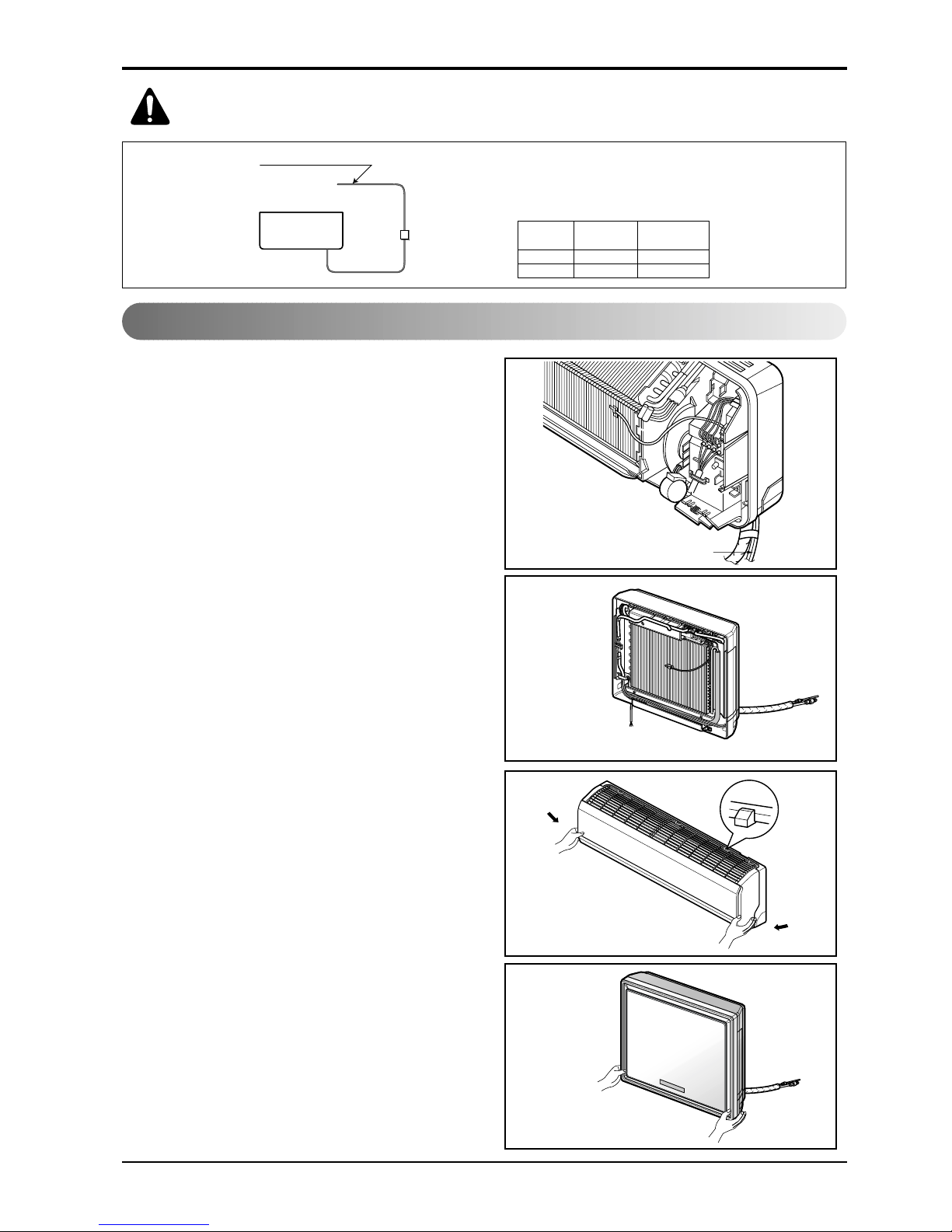
CAUTION: Provide a circuit breaker between power source and the unit
as shown below.
Air
Conditioner
Circuit Breaker
Use a circuit
breaker or time
delay fuse.
Main power source
Model
24k 1ø,230/208V 25A
36k 1ø,230/208V 30A
Power source
Fuse or breaker
Capacity
1. Connect the wires to the terminals on the
control board individually according to the
outdoor unit connection.
• Ensure that the color of the wires of outdoor
unit and the terminal No. are the same as
those of indoor unit respectively.
2. Attach the Grille onto the cabinet.
• Grasp the lower left and right side of the
Grille and engage four tabs on the top inside
edge of the chassis.
• Press the Grille toward the chassis until it
will be back into place.
Connecting cable
Page 23
Installation Manual 23
ENGLISH
Checking the Drainage, Forming the Pipings and Long Pipe Setting
Checking the Drainage , Forming the Pipings and Long Pipe Setting
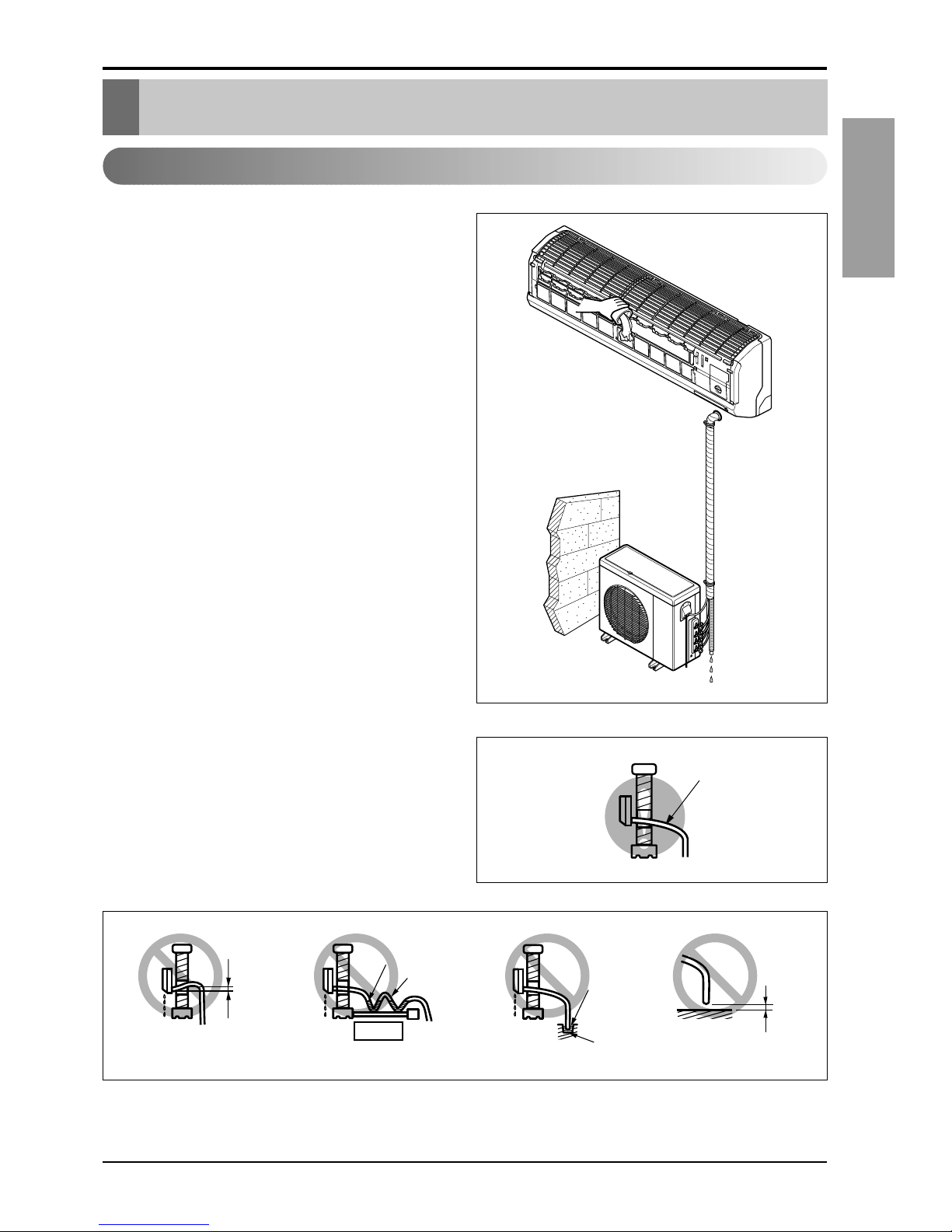
Checking the drainage
To check the drainage.
1. Pour a glass of water on the evaporator.
2. Ensure the water flows through the drain
hose of the indoor unit without any leakage
and goes out the drain exit.
Drain piping
1.The drain hose should point downward for
easy drain flow.
2. Do not make drain piping.
Downward slope
Do not raise
Accumulated
drain water
Tip of drain hose
dipped in water
Air
Waving
Water
leakage
Water
leakage
Ditch
Less than
50mm gap
Water
leakage
Page 24
24 Room Air Conditioner
Checking the Drainage, Forming the Pipings and Long Pipe Setting
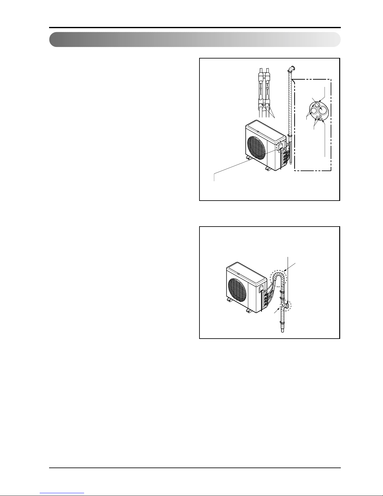
Forming the piping
Form the piping by wrapping the
connecting portion of the indoor
unit with insulation material and
secure it with two kinds of vinyl
tape.
• If you want to connect an additional drain
hose, the end of the drain outlet should be
routed above the ground.Secure the drain
hose appropriately.
In cases where the outdoor unit is
installed below the indoor unit
perform the following.
1.Tape the piping, drain hose and connecting
cable from down to up.
2. Secure the tapped piping along the exterior
wall using saddle or equivalent.
In cases where the Outdoor unit is
installed above the Indoor unit
perform the following.
1.Tape the piping and connecting cable from
down to up.
2. Secure the taped piping along the exterior
wall. Form a trap to prevent water entering
the room.
3. Fix the piping onto the wall by saddle or
equivalent.
Seal a small opening
around the pipings
with gum type sealer.
Trap
Trap
• Trap is required to prevent water from entering
into electrical parts.
Plastic
band
Taping
Drain hose
Pipings
Connecting
cable
Power supply
cord
Seal a small
opening around
the pipings with
gum type sealer.
Page 25
Installation Manual 25
ENGLISH
Air Purging and Evacuation
Air Purging and Evacuation
Air and moisture remaining in the refrigerant system have undesirable effects as indicated below.
1. Pressure in the system rises.
2. Operating current rises.
3. Cooling(or heating) efficiency drops.
4. Moisture in the refrigerant circuit may freeze and block capillary tubing.
5.Water may lead to corrosion of parts in the refrigeration system.
Therefore, the indoor/outdoor unit and connecting tube must be checked for leak tight, and
vacuumed to remove incondensible gas and moisture in the system.
Preparation
• Check that each tube(both liquid and gas side
tubes) between the indoor and outdoor units have
been properly connected and all wiring for the test
run has been completed. Remove the service
valve caps from both the gas and the liquid side
on the outdoor unit. Check that both the liquid and
the gas side service valves on the outdoor unit
are kept closed at this stage.
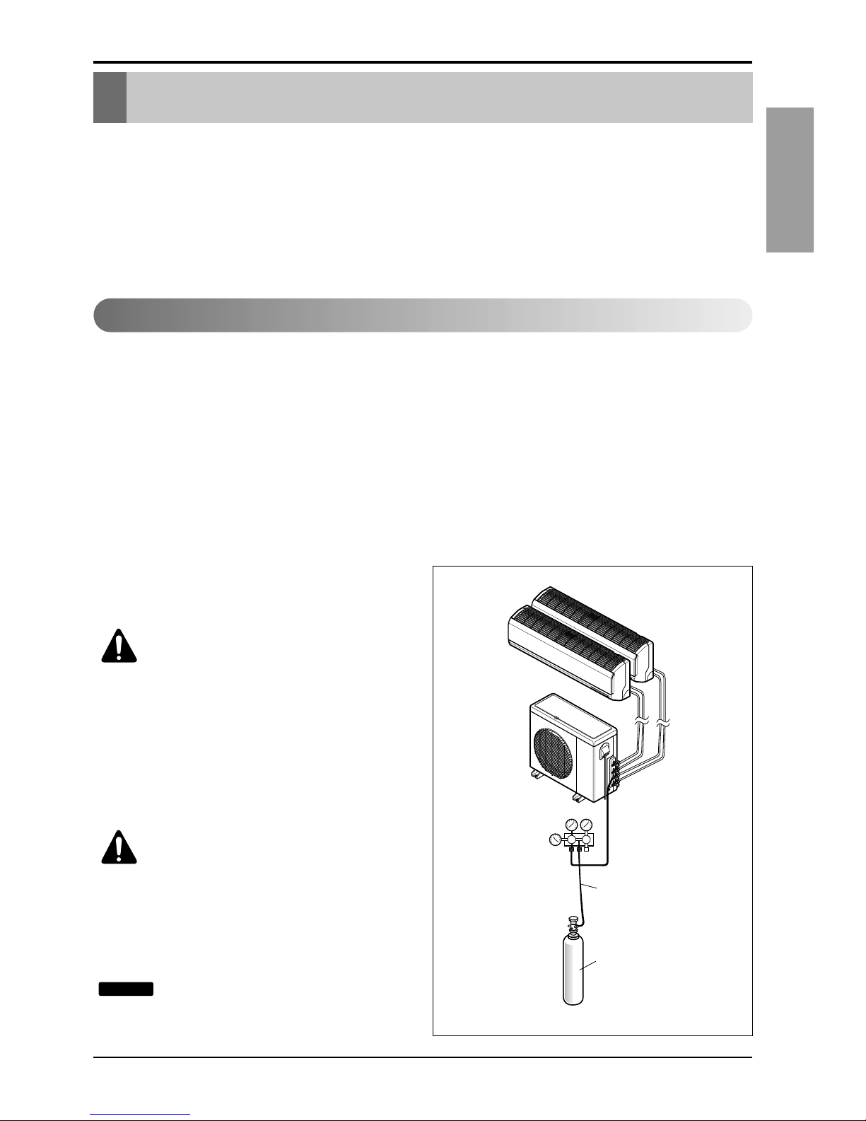
Leakage test
• Connect the manifold valve(with pressure gauges)
and dry nitrogen gas cylinder to this service port
with charge hoses.
CAUTION: Be sure to use a
manifold valve for leak testing.
The high side manifold valve must
always be kept closed.
• Pressurize the system to no more than 150
P.S.I.G.with dr y nitrogen gas and close the
cylinder valve when the gauge reading
reached 150 P.S.I.G.Next, test for leaks with
liquid soap.
CAUTION:
To avoid nitrogen
entering the refrigerant system in a
liquid state, the top of the cylinder must be
higher than its bottom when you pressurize
the system. Usually, the cylinder is used in
a vertical standing position.
:
Leakage test shoud be done for
each indoor unit connection set, separately.
1. Do a leakage test of all joints of the
tubing(both indoor and outdoor) and both gas
and liquid side service valves.
Bubbles indicate a leak. Be sure to wipe off
the soap with a clean cloth.
2. After the system is found to be free of leaks,
relieve the nitrogen pressure by loosening the
charge hose connector at the nitrogen
cylinder.When the system pressure is
reduced to normal, disconnect the hose from
the cylinder.
NOTICE
Checking method
Charge hose
Nitrogen gas
cylinder(in vertical
standing position)
Indoor unit
Outdoor unit
Lo Hi
Manifold valve
Pressure
gauge
Page 26
26 Room Air Conditioner
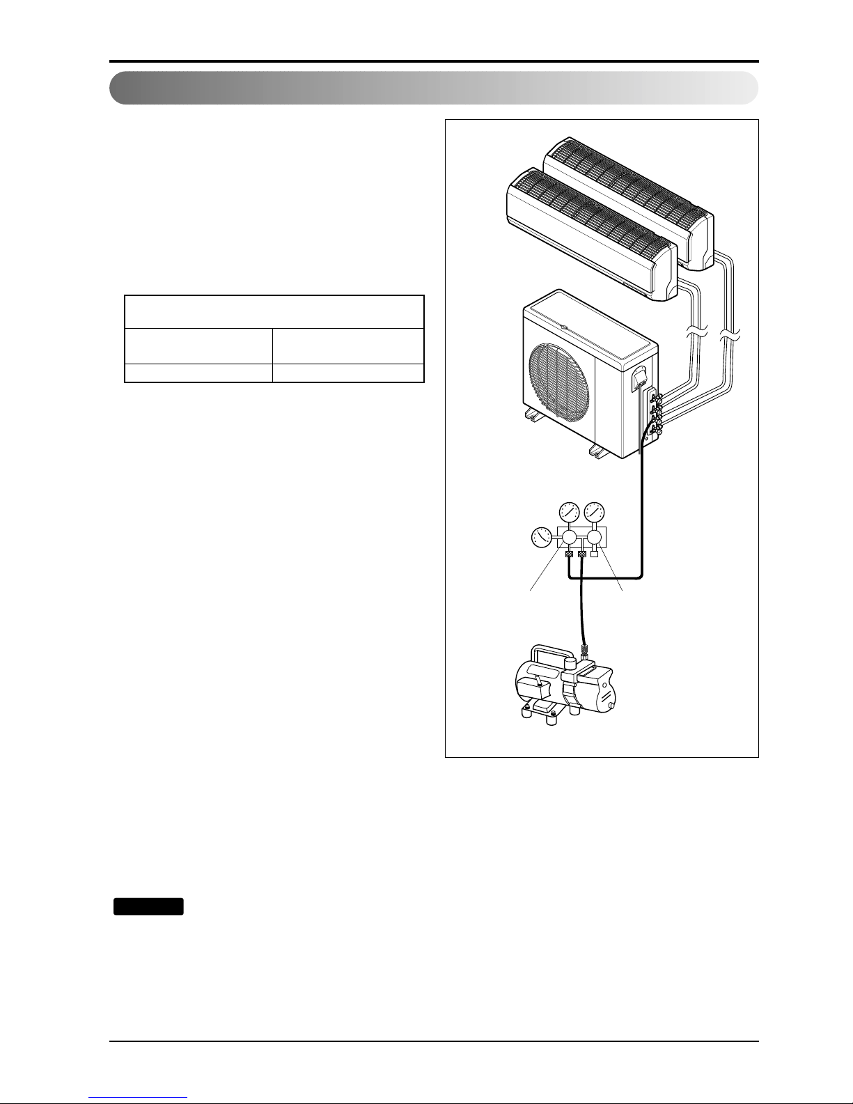
1. Connect the charge hose end described in
the preceding steps to the vacuum pump to
evacuate the tubing and indoor unit.
Confirm the "Lo" knob of the manifold valve is
open.Then, r un the vacuum pump.
The operation time for evacuation varies with
tubing length and capacity of the pump.The
following table shows the time required for
evacuation.
2.When the desired vacuum is reached, close
the "Lo" knob of the manifold valve and stop
the vacuum pump.
Finishing the job
1.With a ser vice valve wrench, turn the valve
stem of liquid side valve counter-clockwise to
fully open the valve.
2.Turn the valve stem of gas side valve
counter-clockwise to fully open the valve.
3. Loosen the charge hose connected to the
gas side service por t slightly to release the
pressure, then remove the hose.
4. Replace the flare nut and its bonnet on the
gas side service por t and fasten the flare nut
securely with an adjustable wrench.This
process is very important to prevent leakage
from the system.
5. Replace the valve caps at both gas and liquid
side service valves and fasten them tight.
This completes air purging with a vacuum
pump.
The air conditioner is now ready for test
running.
: Repeat evacuation procedure for each
indoor unit.
NOTICE
Air Purging and Evacuation
Required time for evacuation when 30 gal/h vacuum
pump is used
10 min. or more 15 min. or more
If tubing length is less
than 10m (33 ft)
If tubing length is longer
than 10m (33 ft)
Indoor unit
Outdoor unit
Lo Hi
Manifold valve
Vacuum pump
Pressure
gauge
Open
Close
Evacuation
Page 27
Installation Manual 27
ENGLISH
Charging
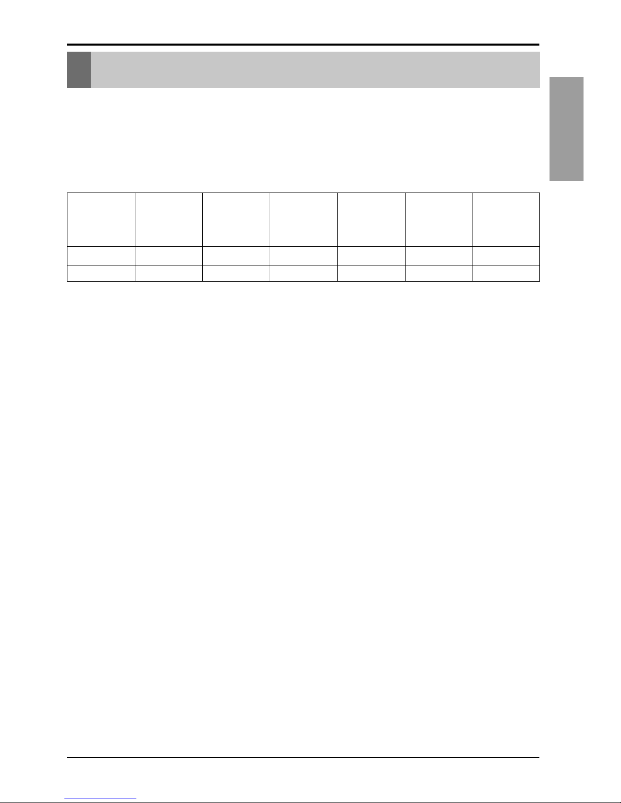
■ Each outdoor unit is factory charged (nameplate charge) for the evaporator as well as a
7.5m(25ft) line set for each indoor line.
Any time total line set is used either shorter or longer then the nominal 22.5m(75ft: for tri-zone)
line set length the refrigerant charge has to be adjusted.
■ Whether the line set is made shor ter or longer you must adjust the charge based on how many ft
of tubing are either added or removed based on 20g(0.22oz) of R-410A per meter(foot).
Example: A 80ft line set is used for tri - zone 5 additional ft X 0.22 ounces per foot= add 1.1
ounces of R-410A
Important:
If you are ever uncertain of the unit charge, reclaim, evacuate and weigh in the correct charge using
the unit nameplate charge adjusting for line sets longer or shorter than 7.5m(25ft) for each indoor
unit.
Charging
24k 30m(100ft) 15m(50ft) 3m(10ft) 7.5m(25ft) 7.5m(25ft) 20g/m(0.22oz/ft)
36k 45m(150ft) 15m(50ft) 3m(10ft) 7.5m(25ft) 7.5m(25ft) 20g/m(0.22oz/ft)
Capacity
(Btu/h)
Max total
length of all
pipes (A+B+C)
Max length of
each pipe
(A/B/C)
Min length of
each pipe
(A/B/C)
Max Elevation
between each
indoor unit and
outdoor unit (h1)
Max elevation
between
indoor units
(h2)
Additional
Refrigerant
Page 28
28 Room Air Conditioner
Panel Front Assembly (Artcool type Only)
Panel Front Assembly (Artcool type Only)
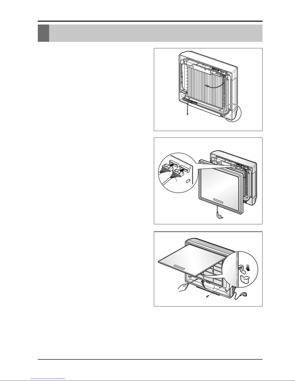
1. First, Check the side cover
assembly exactly, Fix power cord
in the bottom groove of cover side
left.
2. Assemble connecting lead wire
with controller and first fix the
upper part of panel front, then
match the lower part of panel front
3. Suspend hook of front panel in the
groove after contract lower of 2
screws.
Panel F ront
Connector
Page 29
Installation Manual 29
ENGLISH
Test Running
1. Check that all tubing and wiring have been properly connected.
2. Check that the gas and liquid side service valves are fully open.
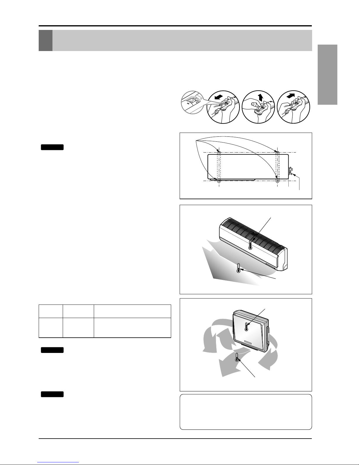
Prepare remote control
Remove the battery cover by pulling it according
to the arrow direction.
Insert new batteries making sure that the (+) and
(–) of battery are installed correctly.
Reattach the cover by pushing it back into
position.
:
• Use 2 AAA(1.5volt) batteries.Do not use
rechargeable batteries.
• Remove the batteries from the remote control if
the system is not going to be used for a long
time.
Evaluation of the performance
Operate all indoor units for 15~20 minutes, then
check the system refrigerant charge:
1.Measure the pressure of one of the gas side
service valves.
2. Measure the temperature of the intake and
discharge of air.
3. Ensure the difference between the intake
temperature and the discharge is more than
8°C(14.4°F).
4. For reference, the gas side pressure of
optimum condition is as below.(Cooling)
:
If the actual pressure are higher than
shown, the system is most likely over-charged, and
charge should be removed.If the actual pressure are
lower than shown, the system is most likely
undercharged, and charge should be added.
: For maximum product life and efficiency
this unit has been designed, in the heating mode, to
lock-out at outdoor temperatures below 26-29°F.
At outdoor temperatures below 26-29°F. another means
of heating the conditioned space must be provided.
NOTICE
NOTICE
NOTICE
Discharge
temperature
Discharge air
Intake temperature
Discharge
temperature
Discharge air
Intake temperature
Bolt
Tubing connection
R-410A 35°C (95°F) 8.5~9.5kg/cm2G(120~135 P.S.I.G.)
Outside ambient
TEMP.
Refrigerant
The pressure of the gas side
service valve.
Important:
❏ Individual zones should be all in the same
operation mode (Heating or Cooling mode)
Test Running
Page 30
30 Room Air Conditioner
Combination indoor units
Combination indoor units
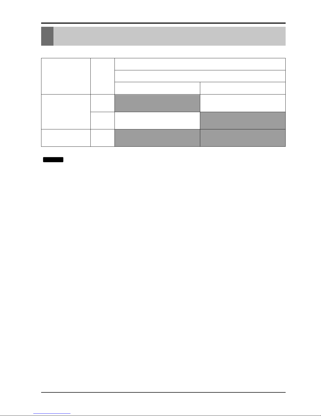
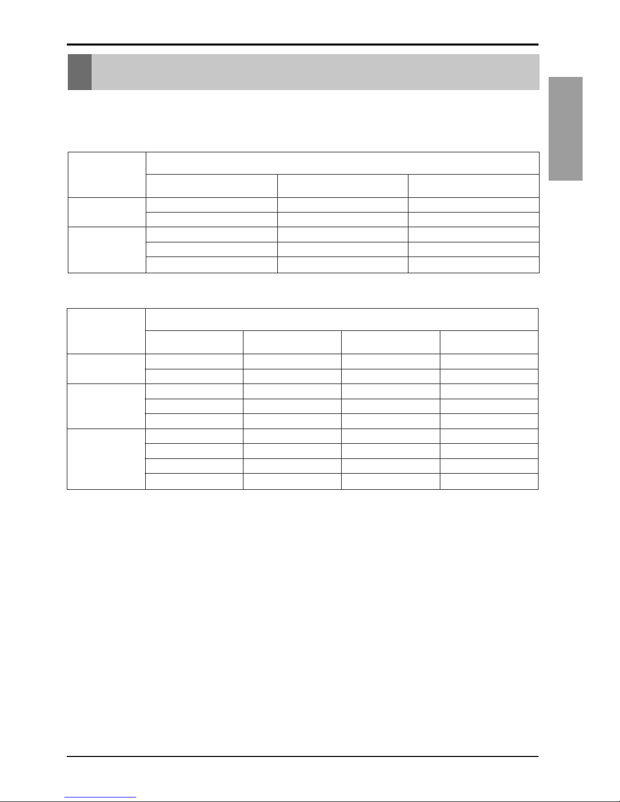
The indoor units connectable to the outdoor unit are shown below.
Type
Standard Type
S4
SE
SP3
Artcool Type
Chassis
Name
Model Name
Capacity, Btu/h
9000 12000
:
1.The total capacity(in Btu/h unit) of connected indoor unit models represents the total sum of the figures
expressed in the indoor model name.
2. Combinations in which the total capacity of the connected indoor units exceeds the capacity of the
outdoor unit will reduce the capacity of each indoor unit below the rated capacity during simultaneous
operation.Therefore, if circumstances allows, combine indoor units within the capacity of the outdoor unit
NOTICE
Page 31
Combination table of Models
Installation Manual 31
ENGLISH
Combination table of ModelsCombination table of Models
❈
This table shows available combination.
Above standard combination, suitable performance may not be obtained depending on operating condition.
24k (2 rooms)
1 UNIT
99
12 12
2 UNIT
9918
91221
12 12 24
Combination
Unit-A Unit-B Total
36k (3 rooms)
1 UNIT
99
12 12
99 18
912 21
2 UNIT
12 12 24
99927
3 UNIT
9 9 12 30
9121233
12 12 12 36
Combination
Unit-A Unit-B Unit-C Total
Page 32
32 Room Air Conditioner
Memo
 Loading...