

LG FLATRON W2243T Service Manual
E-mail: http://www.LGEservice.com/techsup.html
COLOR MONITOR
SERVICE MANUAL
MODEL: W2243T (W2243T-PFT.A**NAPH for
LGD TLA1, W2243T-PFT.A**VAPH for AUO V0
CAUTION
BEFORE SERVICING THE UNIT,
READ THE SAFETY PRECAUTIONS IN THIS MANUAL.
*ToapplytheNovatekChip.
) **Sales Market
http://www.wjel.net
- 1 -

CONTENTS
SPECIFICATIONS ...................................................2
PRECAUTIONS .......................................................3
TIMING CHART .......................................................7
DISASSEMBLY ........................................................9
BLOCK DIAGRAM...................................................12
DISCRIPTION OF BLOCK DIAGRAM .................. 14
ADJUSTMENT ...................................................... 16
SERVICE MODE ......................................................... 18
TROUBLESHOOTING GUIDE .............................. 19
WIRING DIAGRAM ................................................... 25
EXPLODED VIEW...................................................... 26
REPLACEMENT PARTS LIST ................................. 28
DIFFERENT PARTS LIST…......................................... 37
SCHEMATIC DIAGRAM.............................................. 38
SPECIFICATIONS
1. LCD CHARACTERISTICS
Type: matrix-TFT Color LCD Module
Active Display Area: 21.53 inches
Pixel Pitch: 0.248 (H) x 0.248 (V)mm
Color Depth: 16.7M colors
Size: 495.6(W) x 292.2(H) x 16.35(D) mm(Typ.)
Display Mode: LTN Mode, Normally White
Surface Treatment: Anti-Glare, 3H
Electrical Interface: Dual channel LVDS
2. OPTICAL CHARACTERISTICS
2-1. Viewing Angle by Contrast Ratio > 10
Left: 150°min, 170°(Typ) Right: 150°min, 170°(Typ)
Top: 140° min, 160°(Typ) Bottom: 140°min,160°(Typ)
2-2. White Luminance ( Center ): 300Cd / m
2-3. Contrast Ratio: 600(min), 1000(Typ)
3. SIGNAL (Refer to the Timing Chart)
3-1. Sync Signal
Type: Separate Sync, SOG (Sync On Green) / Digital
3-2. Video Input Signal
1) Type: R, G, B Analog, Digital
2) Voltage Level: 0~0.7 Vp-p
3) Input impedance: 75
3-3. Operating Frequency
Horizontal: 30 ~ 83kHz
Vertical: 56 ~ 75Hz
http://www.wjel.net
2
(Typ)
4. Max. Resolution
D-sub Analog: VESA 1920 x 1080 @ 60 Hz
5. POWER SUPPLY
5-1. Power: AC 100-240V~ 50/60Hz 1.0A
5-2. Power Consumption
On Mode: 40 W(Typ.)
Sleep Mode: 1 W
Off Mode: 1 W
6. ENVIRONMENT
6-1. Operating
Temperature: 10°C~35°C
Humidity: 10 % to 80 % non-Condensing
6-2. Storage
Temperature: -20°C to 60 °C
Humidity: 5 % to 90 % non-Condensing
6-3. MTBF: 70000 Hours (Not include panel)
Lamp Life: 50000 Khrs
7. DIMENSIONS (with Stand)
Width: 51.64 cm (20.33 inches)
Depth: 19.80 cm (7.80 inches)
Height: 39.61 cm (15.59 inches)
8. WEIGHT (excl. packing)
Weight: 3.8 kg (8.38 lbs)
- 2 -
http://www.wjel.net
- 3 -
http://www.wjel.net
- 4 -
http://www.wjel.net
- 5 -

http://www.wjel.net
- 6 -
Mode Section Polarity
DOT
CLOCK
[MHz]
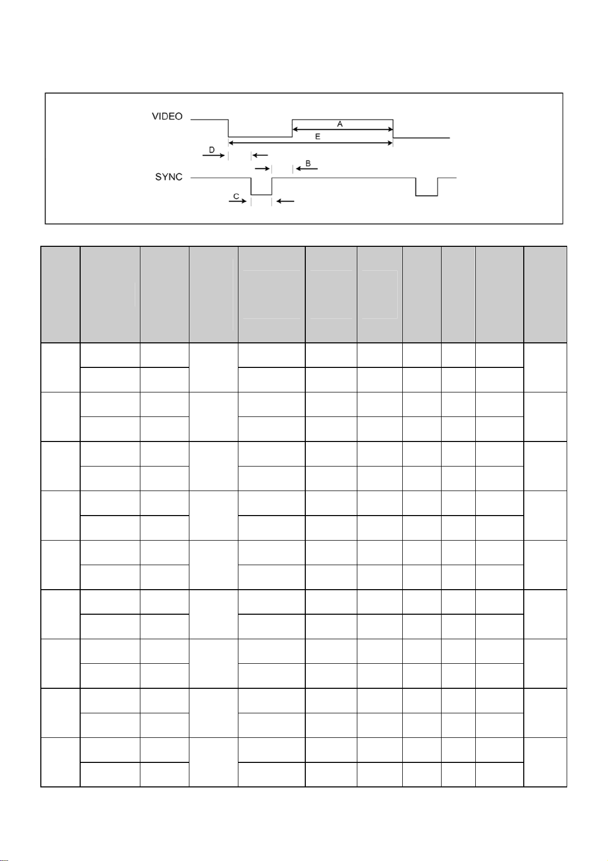
TIMING CHART
Frequency
[kHz]/[Hz]
Total
Period(E)
Display
(A)
Front
Porc
h
(D)
Syn
c.
(C)
Back
Porch
(B)
Resol-
ution
1
2
3
4
5
6
7
H(Pixels) + 31.469 800 640 16 96 48
25.175
V(Lines) -
H(Pixels) - 31.468 900 720 18 108 54
28.321
V(Lines) +
H(Pixels) - 31.469 800 640 16 96 48
25.175
V(Lines) -
H(Pixels) - 37.5 840 640 16 64 120
31.5
V(Lines) -
H(Pixels) + 37.879 1056 800 40 128 88
40.0
V(Lines) +
H(Pixels) + 46.875 1056 800 16 80 160
49.5
V(Lines) +
H(Pixels) +/- 49.725 1152 832 32 64 224
V(Lines) +/-
http://www.wjel.net
57.283
70.09 449 350 37 2 60
720 X
70.08 449 400 12 2 35
59.94 525 480 10 2 33
75 500 480 1 3 16
60.317 628 600 1 4 23
75.0 625 600 1 3 21
74.55 667 624 1 3 39
640 x
350
400
640 x
480
640 x
480
800 x
600
800 x
600
832 x
624
8
9
H(Pixels) - 48.363 1344 1024 24 136 160
65.0
V(Lines) -
H(Pixels) - 60.123 1312 1024 16 96 176
78.75
V(Lines) -
60.0 806 768 3 6 29
75.029 800 768 1 3 28
- 7 -
1024 x
1024 x
768
768
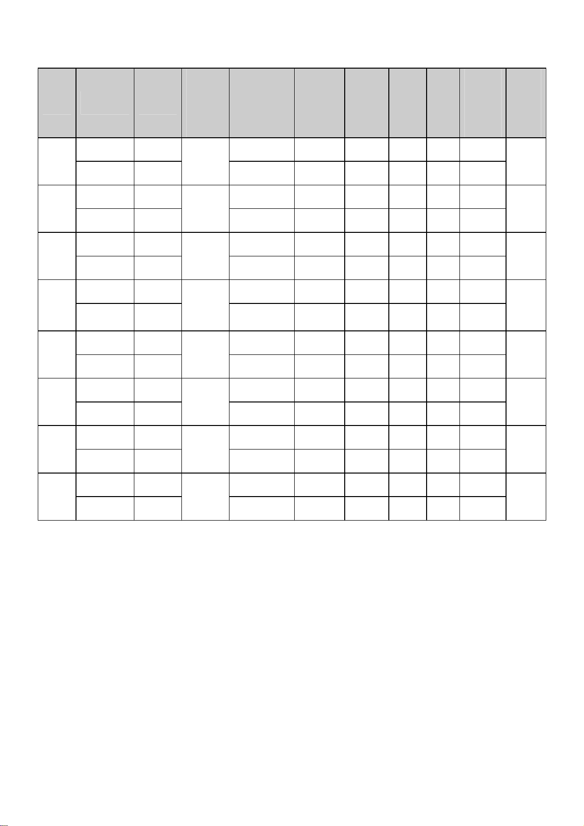
Mode Section Polarity
H(Pixels) +/- 68.681 1456 1152 32 128 144
10
V(Lines) +/-
H(Pixels) +/- 61.805 1504 1152 18 134 200
11
V(Lines) +/-
H(Pixels) + 63.981 1688 1280 48 112 248
12
V(Lines) +
H(Pixels) + 79.976 1688 1280 16 144 248
13
V(Lines) +
H(Pixels) + 64.674 1840 1680 48 32 80
14
V(Lines) -
DOT
CLOCK
[MHz]
100.0
92.978
108.0
135.0
119.00
Front
Frequency
[kHz]/[Hz]
75.062 915 870 3 3 39
65.96 937 900 2 4 31
60.02 1066 1024 1 3 38
75.035 1066 1024 1 3 38
59.883 1080 1050 3 6 21
Total
Period(E)
Display
Porch
(A)
(D)
Sync
.
(C)
Back
Porch
(B)
Resol-
ution
1152 x
870
1152 x
900
1280 x
1024
1280 x
1024
1680 x
1050
15
16
17
H(Pixels) - 65.290 2240 1680 104 176 280
146.250
V(Lines) +
H(Pixels) + 63.981 1688 1280 48 112 248
105.982
V(Lines) +
H(Pixels) + 67.5 2200 1920 88 44 143
148.50
V(Lines) +
59.954 1089 1050 3 6 30
60.02 1062 1024 1 3 34
60 1125 1080 4 5 36
1680 x
1280 x
1920 x
http://www.wjel.net
1050
1024
1080
- 8 -
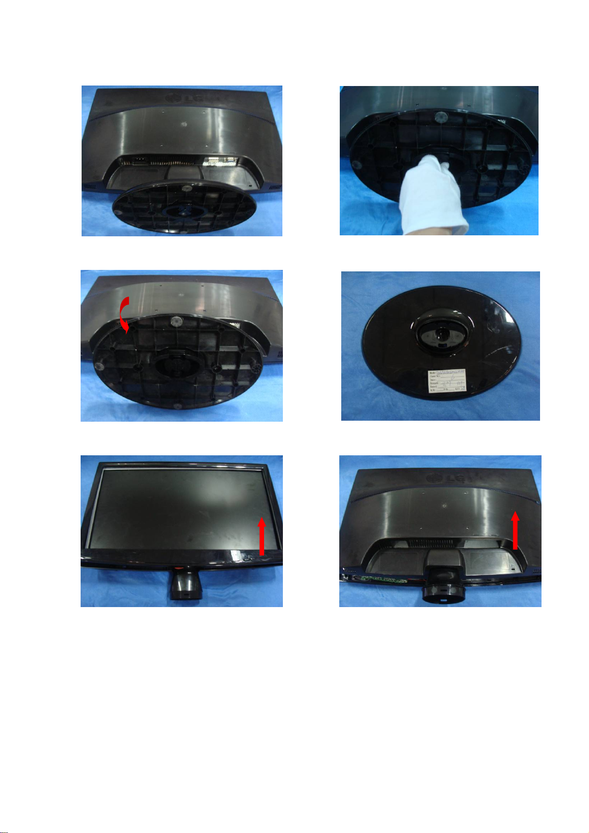
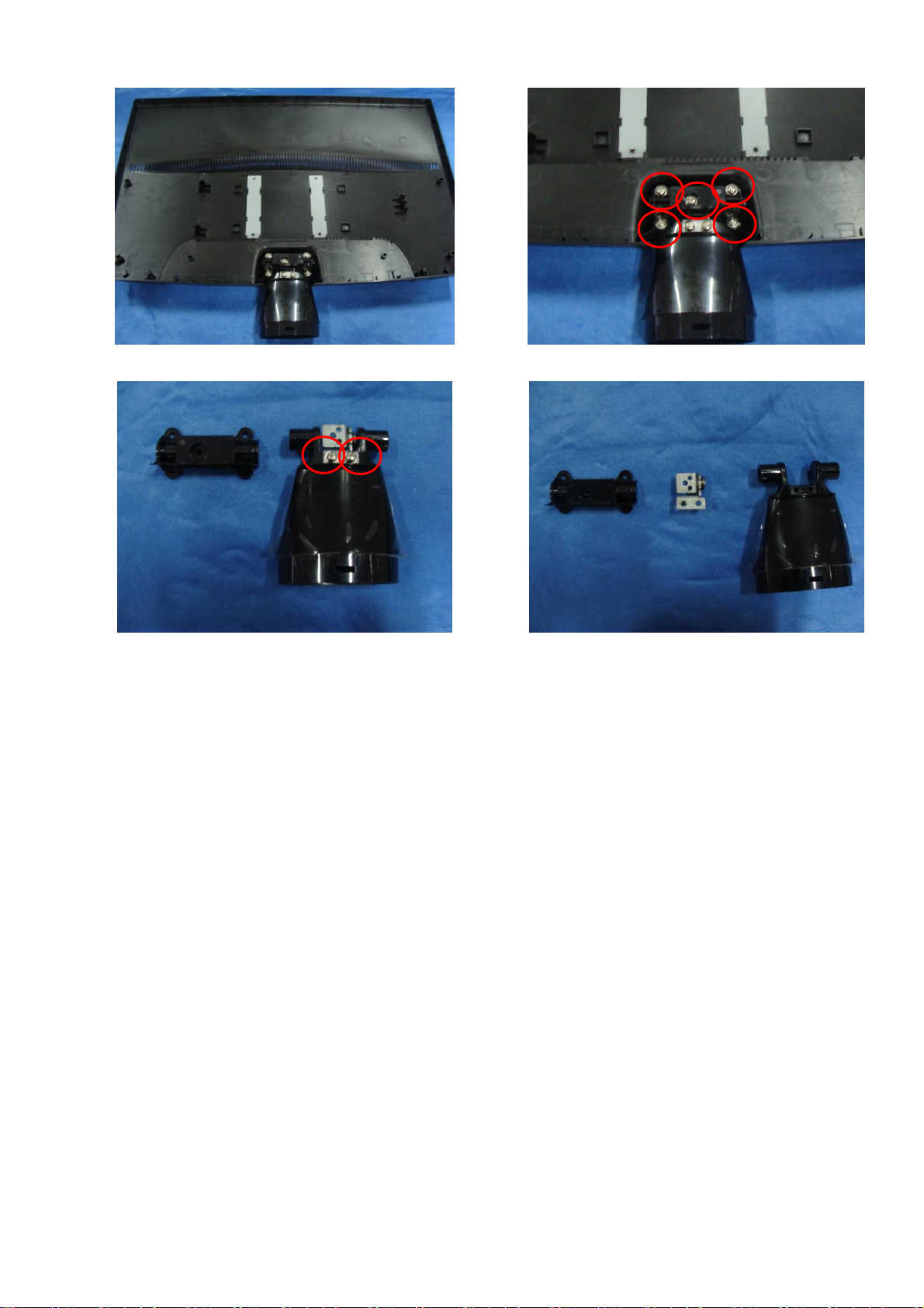
DISASSEMBLY-Set
#1
Put the monitor on a soft flat.
#3
#2
Revolve the release button.
#4
Consequently, pull the base directly.
#5
http://www.wjel.net
Put the front cover upward. Then let the all
latches are separated.
#6
The base.
Put the front face down, disassembly back
cover.
- 9 -
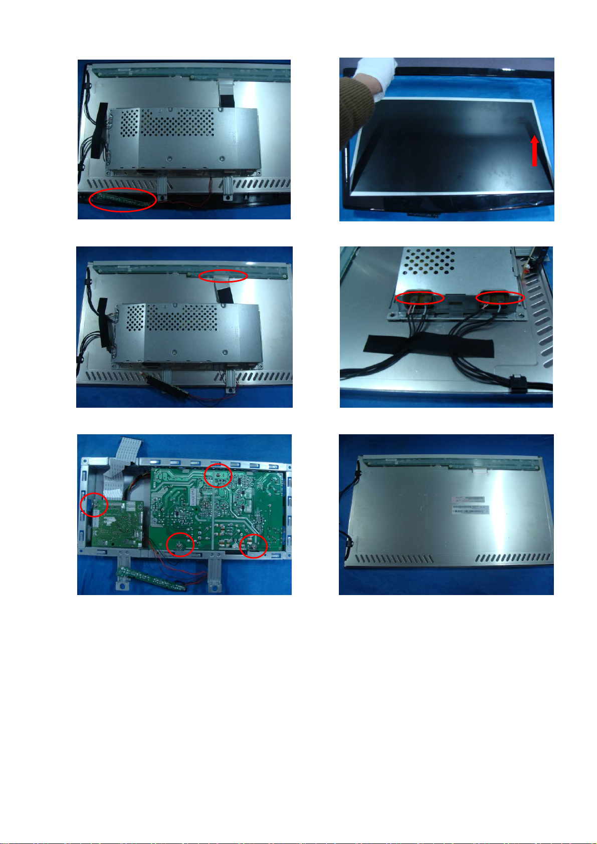
#7
#8
Pull the key board out of bezel.
#9
Disassembly the LVDS cable.
#11
Disassembly the bezel.
#10
Disassemble the connector.
#12
Main board and power board.
http://www.wjel.net
The panel.
- 10 -
#13
#14
Rear cover and hinge ASS’Y.
#15
Disassemble the hinge and stand.
Disassemble the rear cover and hinge ASS’Y.
#16
Hinge top, hinge and stand.
http://www.wjel.net
- 11 -
BLOCK DIAGRAM
http://www.wjel.net
- 12 -
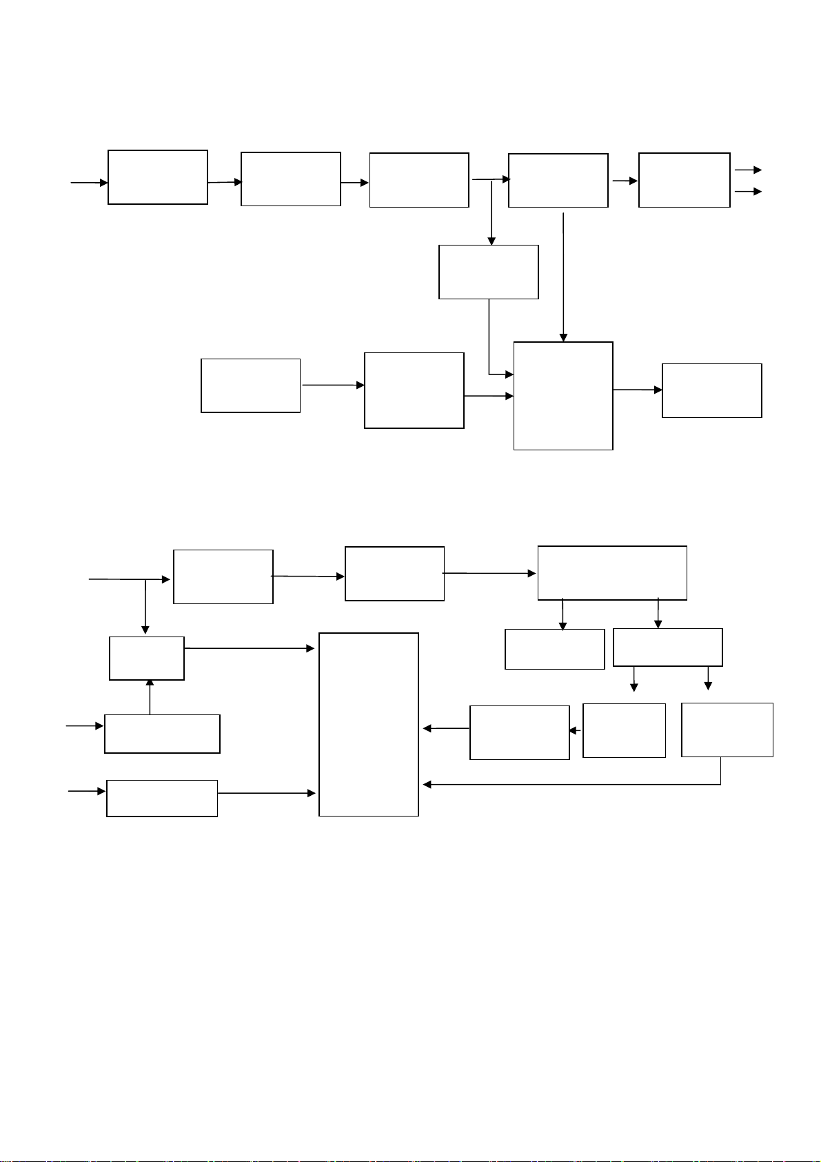
Power
BLOCK DIAGRAM-POWER
100~240V
Inverter
EMI filter
16V
5V/16V
output OVP
Push-pull
circuit
Rush
prevention
Rectification
Feedback
control
circuit
Transformer
conversion
Starting
resistor
Transformer
Switching
circuit (PWM
control IC &
MOSFER)
LC resonance
Diode
rectifier
OVP protect
circuit
5V
16V
ON/OFF
ON/OFF circuit
DIM
VDDA
DIM circuit
PWM IC
ta9687GN
OVP circuit
Feedback
circuit
2 CCFL lamps
Sampling
Lamp open
protection
http://www.wjel.net
- 13 -

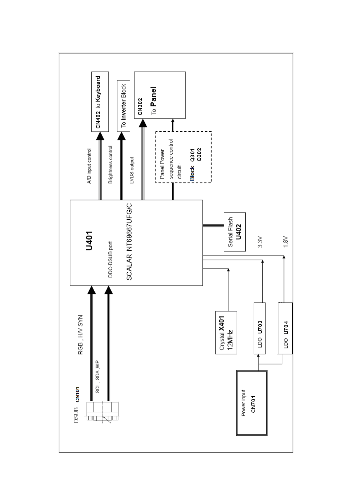
DESCRIPTION OF BLOCK DIAGRAM
1. Video Controller Part.
This part amplifies the level of video signal for the digital conversion and converts from the analog video signal to
the digital video signal using a pixel clock.
The pixel clock for each mode is generated by the PLL.
The range of the pixel clock is from 25MHz to 148.5MHz.
This part consists of the Scalar, ADC converter, TMDS receiver and LVDS transmitter.
The Scalar gets the video signal converted analog to digital, interpolates input to 1920 X 1080 resolution signal and
outputs 8-bit R, G, B signal to transmitter.
2. Power Part.
This part consists of the one 3.3V, and one 1.8V regulators to convert power which is provided 5V in Power board.
16V is provided for inverter, 5V is provided for LCD panel.
Also, 5V is converted 3.3V and 1.8V by regulator. Converted power is provided for IC in the main board.
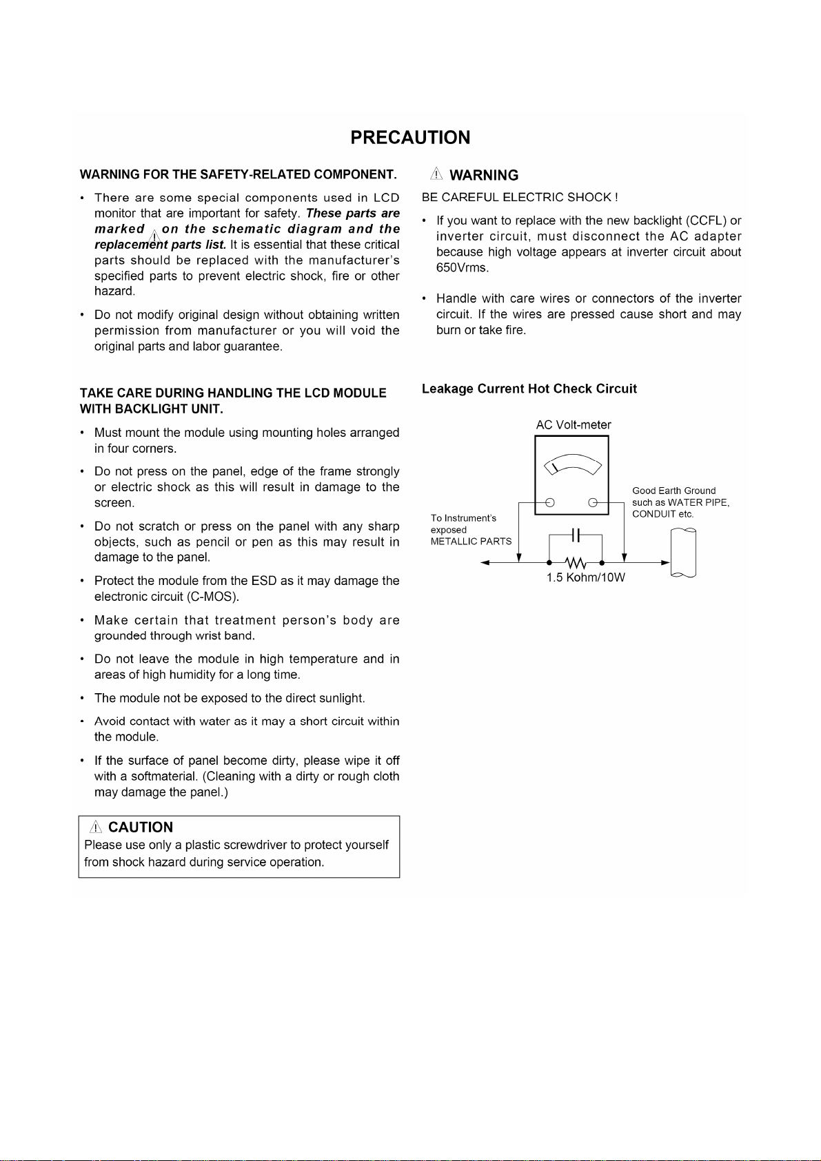
The inverter converts from DC 16V to AC 700Vrms and operates back-light lamps of module.
3. MICOM Part.
This part is including video controller part. And this part consists of Reset IC and the Micom.
The Micom distinguishes polarity and frequencies of the H/V sync are supplied from signal cable.
The controlled data of each mode is stored in scalar.
http://www.wjel.net
- 14 -
 Loading...