

LG Flatron L3020T, Flatron L3020A, Flatron L3020AL-ALT, Flatron L3020AL-ALA, Flatron AGA Service Monitor
COLOR MONIT OR
SER VICE MANUAL
Website:http://biz.LGservice.com
E-mail:http://www.LGEservice.com/techsup.html
CAUTION
BEFORE SERVICING THE UNIT,
READ THE SAFETY PRECAUTIONS IN THIS MANUAL.
CHASSIS NO. : CL-49
MODEL: L3020T (L3020AL-AL**T)
L3020A (L3020AL-AL**A)
( ) **Same model for Service
MAIN
1. LCD CHARACTERISTICS
Type : TFT Color LCD Module
Size : 30inch
Pixel Pitch : 0.5025 x 0.1675 x RGB
Color Depth : 8-bit, 16,777,216 colors
Electrical Interface : LVDS
Active Display Area :
643.2mm x 385.92mm -LPL Module
: 683.6mm x 433.6mm -CMO Module
Surface Treatment :
Anti-Glare, Hard Coating(3H) -LPL Module
:
Anti-Glare, Hard Coating(2H) -CMO Module
Operating Mode : Normally Black, Transmissive
Backlight Unit : 16-CCFL (Cold Cathode
Fluorescent Lamp)
2. OPTICAL CHARACTERISTICS
2-1. Viewing Angle by Contrast Ratio
≥
10
Left : -80° min., -85°(Typ)
Right : +80° min., +85°(Typ)
Top : +80° min., +85°(Typ)
Bottom : -80° min., -85°(Typ)
2-2. Luminance : 380(min), 450(Typ)
-LPL Module
450(min), 500(Typ)
-CMO Module
2-3. Contrast Ratio : 280(min), 350(Typ)
-LPL Module
500(Typ)
-CMO Module
3. SIGNAL (Refer to the Timing Chart)
3-1. PC & Video Input
1)Signal Input : S-video,RCA, Component
2)Input Form : D-SUB Analog, DVI-D,V1(CVBS)
V2(SVHS), DVD(Ycbcr),HDTV(YPbPr),
TV-NTSC(Opion)
3)Resolution(max) : Analog -1280 x 1024
Digital -1280 x 1024
3-2. Audio Signal
1) Input: PC : 700mVrms
AV : 450mVrms
2) Output: PC : 8W
AV : 8W
3-3. Sync Input
Horizontal : 30 ~ 66kHz(Digital: 30~63kHz)
Vertical : 56 ~ 85Hz
Input Form : Separate, TTL,
Positive/Negative Digital
4. POWER SUPPLY
4-1. Power Adaptor
Input : AC 100~240V, 50/60Hz , 2.0A
Output : DC 5V 0.9A, DC12V 1.5A
DC18V 1.0A, DC24V 5.0A
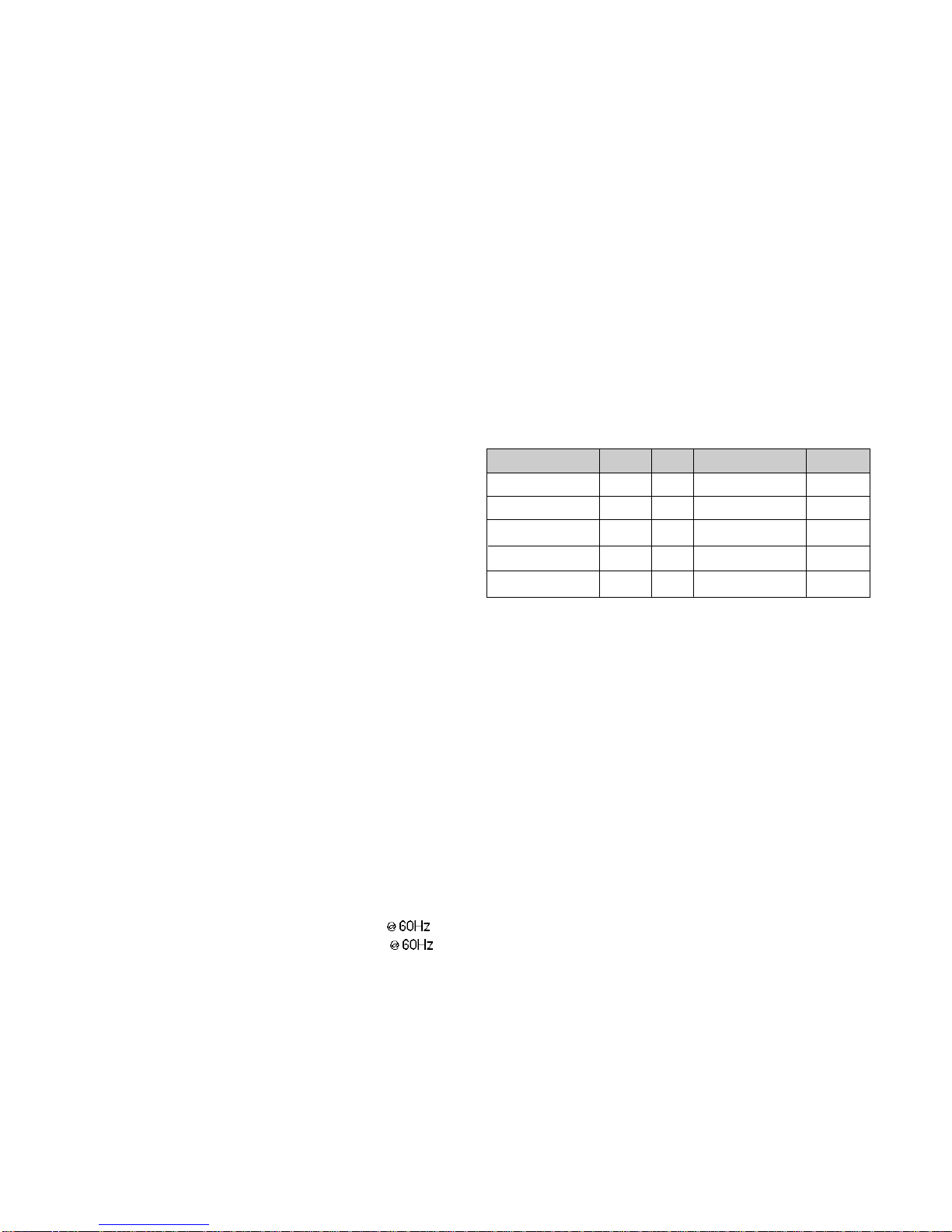
4-2. Power Consumption
5. ENVIRONMENT
6-1. Operating Temperature: 10°C~35°C (50°F~95°F)
6-2. Operating Humidity : 10%~80%
6-3. MTBF : 50,000 Hours(Min.)
6. DIMENSIONS (with TILT/SWIVEL)
Width : 734 mm (28.90'')
Height : 538 mm (21.18'')
Depth : 191 mm (7.52'')
7. WEIGHT (with TILT/SWIVEL)
LPL Module
Net. Weight : 16.4kg (36.16 lbs)
Gross Weight : 21.7kg (47.84 lbs)
CMO Module
Net. Weight : 17kg (37.48 lbs)
Gross Weight : 22.5kg (49.61 lbs)
CONTENTS
SPECIFICATIONS
- 2 -
SPECIFICATIONS ................................................... 2
PRECAUTIONS ....................................................... 4
TIMING CHART ....................................................... 5
OPERATING INSTRUCTIONS ................................ 6
WIRING DIAGRAM ............................................... 10
BLOCK DIAGRAM ................................................. 12
DESCRIPTION OF BLOCK DIAGRAM...................13
ADJUSTMENT ...................................................... 14
TROUBLESHOOTING GUIDE .............................. 16
EXPLODED VIEW...................................................23
REPLACEMENT PARTS LIST ...............................25
PIN CONFIGURATION............................................35
SCHEMATIC DIAGRAM......................................... 37
MODE
POWER ON (NORMAL)
STAND-BY
SUSPEND
POWER OFF
CUT-OFF SWITCHOFF
H/V SYNC
ON/ON
OFF/ON
ON/OFF
OFF/OFF
-
POWER CONSUMPTION
less than 160 W
less than 5 W
less than 5 W
less than 5 W
less than 1 W
LED COLOR
GREEN
AMBER
AMBER
AMBER
OFF
VIDEO
ACTIVE
OFF
OFF
OFF
-
- 3 -
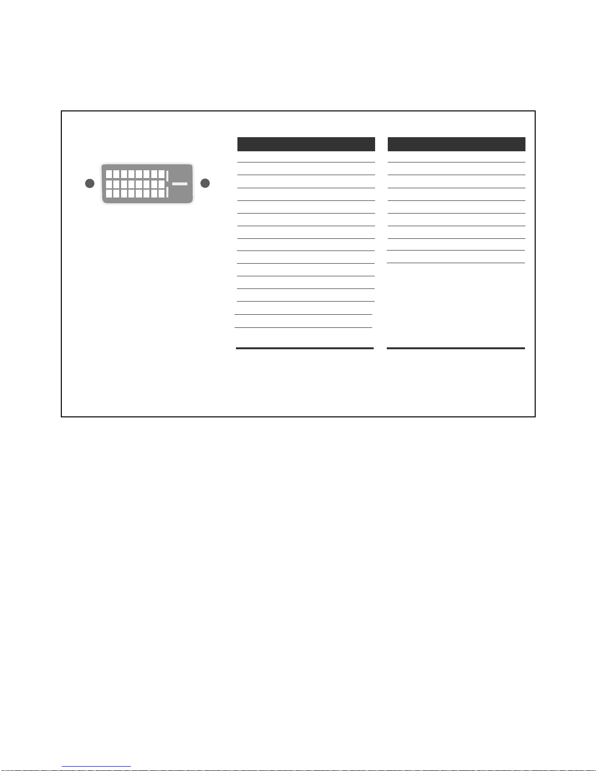
Signal Connector Pin Assignment
Pin Signal (DVI-D)
1
2
3
4
5
6
7
8
9
10
11
12
13
14
15
T. M. D. S. Data2T. M. D. S. Data2+
T. M. D. S. Data2/4 Shield
T. M. D. S. Data4T. M. D. S. Data4+
DDC Clock
DDC Data
Analog Vertical Sync.
T. M. D. S. Data1T. M. D. S. Data1+
T. M. D. S. Data1/3 Shield
T. M. D. S. Data3T. M. D. S. Data3+
+5V Power
Ground
(return for +5V,
H. Sync. and V. Sync.)
Pin Signal (DVI-D)
1
8
9
17
24
16
16
17
18
19
20
21
22
23
24
Hot Plug Detect
T. M. D. S. Data0T. M. D. S. Data0+
T. M. D. S. Data0/5 Shield
T. M. D. S. Data5T. M. D. S. Data5+
T. M. D. S. Clock Shield
T. M. D. S. Clock+
T. M. D. S. Clock-
T. M. D. S. (Transition Minimized Differential Signaling)
• DVI-D Connector (Digital)
- 4 -
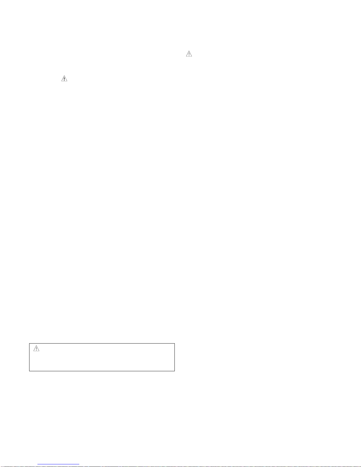
WARNING FOR THE SAFETY-RELATED COMPONENT.
• There are some special components used in LCD
monitor that are important for safety. These parts are
marked on the schematic diagram and the
replacement parts list. It is essential that these critical
parts should be replaced with the manufacturer’s
specified parts to prevent electric shock, fire or other
hazard.
• Do not modify original design without obtaining written
permission from manufacturer or you will void the
original parts and labor guarantee.
TAKE CARE DURING HANDLING THE LCD MODULE
WITH BACKLIGHT UNIT.
• Must mount the module using mounting holes arranged
in four corners.
• Do not press on the panel, edge of the frame strongly
or electric shock as this will result in damage to the
screen.
• Do not scratch or press on the panel with any sharp
objects, such as pencil or pen as this may result in
damage to the panel.
• Protect the module from the ESD as it may damage the
electronic circuit (C-MOS).
• Make certain that treatment person’s body are
grounded through wrist band.
• Do not leave the module in high temperature and in
areas of high humidity for a long time.
• The module not be exposed to the direct sunlight.
• Avoid contact with water as it may a short circuit within
the module.
• If the surface of panel become dirty, please wipe it off
with a softmaterial. (Cleaning with a dirty or rough cloth
may damage the panel.)
WARNING
BE CAREFUL ELECTRIC SHOCK !
• If you want to replace with the new backlight (CCFL) or
inverter circuit, must disconnect the AC adapter
because high voltage appears at inverter circuit about
650Vrms.
• Handle with care wires or connectors of the inverter
circuit. If the wires are pressed cause short and may
burn or take fire.
PRECAUTION
CAUTION
Please use only a plastic screwdriver to protect yourself
from shock hazard during service operation.
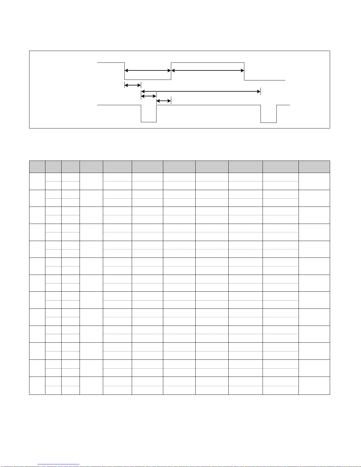
TIMING CHART
- 5 -
VIDEO
SYNC
B
D
C
F
E
A
<< Dot Clock (MHz), Horizontal Frequency (kHz), Vertical Frequency (Hz), Horizontal etc... (µs), Vertical etc... (ms) >>
H + 31.469 800 640 16 96 48
V – 70.8 449 350 37 2 60
H – 43.269 832 640 56 56 80
V – 85.0 509 480 1 3 25
H – 31.469 800 640 16 96 48
V – 59.94 525 480 10 2 33
H – 37.5 840 640 16 64 120
V – 75 500 480 1 3 16
H – 31.468 900 720 18 108 54
V + 70.8 449 400 12 2 35
H + 37.879 1056 800 40 128 88
V + 60.317 628 600 1 4 23
H + 46.875 1056 800 16 80 160
V + 75.0 625 600 1 3 21
H + 53.674 1048 800 32 64 152
V + 85.061 631 600 1 3 27
H+/– 49.725 1152 832 32 64 224
V+/– 74.55 667 624 1 3 39
H – 48.363 1344 1024 24 136 160
V – 60.0 806 768 3 6 29
H – 60.123 1312 1024 16 96 176
V – 75.029 800 768 1 3 28
H + 63.981 1688 1280 48 112 248
V + 60.02 1066 1024 1 3 38
H + 47.7 1680 1280 66 134 200
V + 60 795 768 1 3 23
Mode
H/V
Sort
1
2
3
4
5
6
7
8
9
10
11
12
13
25.175
28.321
25.175
31.5
36.0
40.0
49.5
56.25
57.283
65.0
78.75
108.0
80.14
640x350
70Hz
640x480
85Hz
640x480
60Hz
640x480
75Hz
720x400
70Hz
800x600
60Hz
800x600
75Hz
800x600
85Hz
832x624
75Hz
1024x768
60Hz
1024x768
75Hz
1280x1024
60Hz
1280x768
60Hz
Sync
Polarity
Frequency
Dot
Clock
Total Period
(E)
Video Active Time
(A)
Sync Duration
(D)
Back Porch
(F)
Front Porch
(C)
Resolution
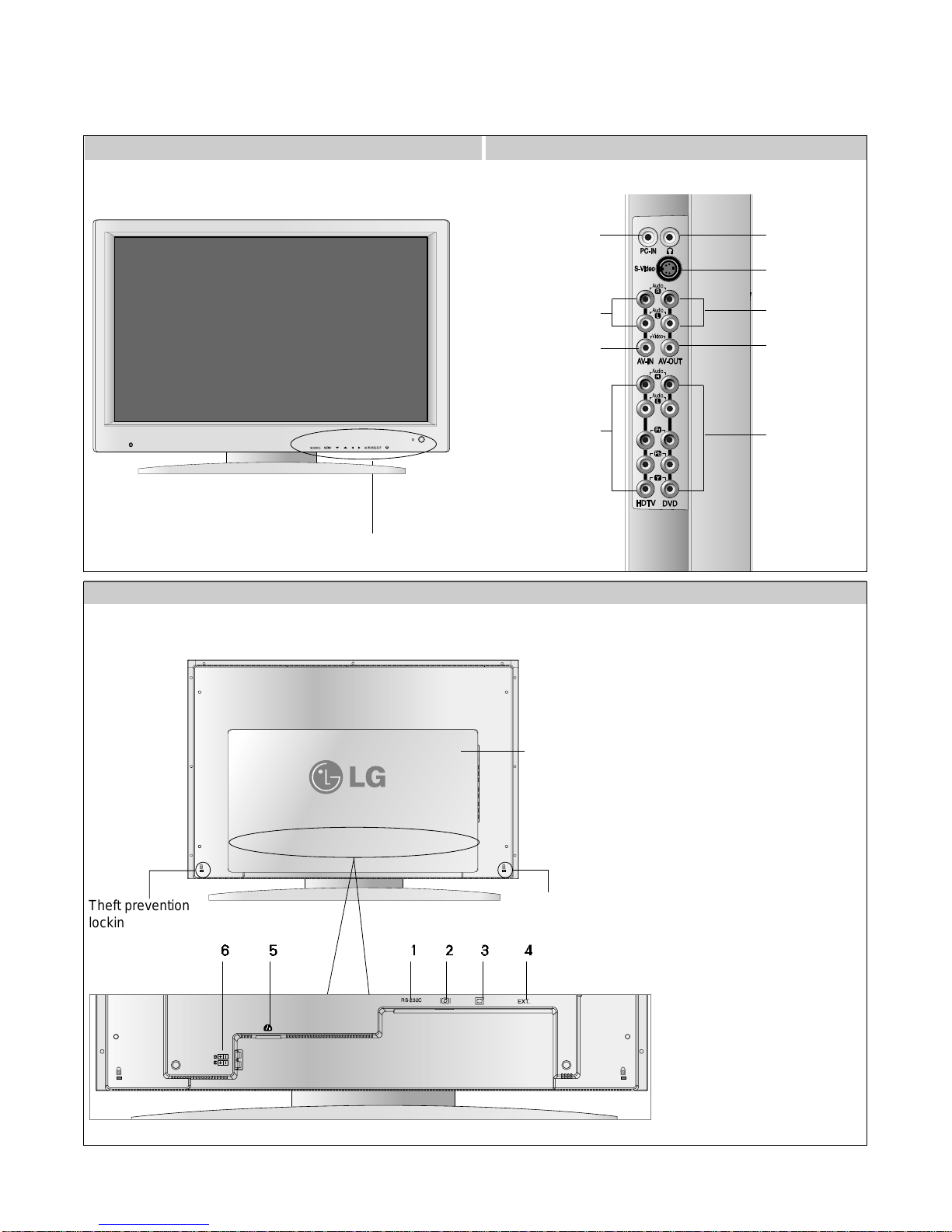
- 6 -
FRONT VIEW
REAR VIEW CONNECTOR PANEL
REAR VIEW
OPERATING INSTRUCTIONS
Front Control Panel(P7)
RS-232C EXT.
Theft prevention
locking device
Theft prevention
locking device
Back
Cap
1.
RS-232C Terminal
: The RS-232C protocol is used for communication
between the PC and monitor. You can turn the
monitor on/off, seslect an input source or adjust the
OSD menu from your PC.
The cable for RS-232C terminal connection is not an
accessory included in the product.
Please purchase the cable.
2. DVI Digital Signal Connector
3. D-SUB Analog Signal Connector
4. TV Tuner Jack: Connect the antenna.
-L3020T(Option)
5. Connect the power cord
6. Speaker Terminal: Connect the speaker
PC Audio Input Terminal
-Connect the audio cable
to the LINE OUT jack in the
PC sound card
Headphone/earphone
Connection Terminal
S-Video Input Terminal
AV Output Terminal
(Audio)
DVD Input Terminal
AV Input Terminal(Audio)
AV Output Terminal
(Video)
AV Input Terminal(Video)
HDTV Input Terminal
MAIN
RS-232C
EXT.
- 7 -
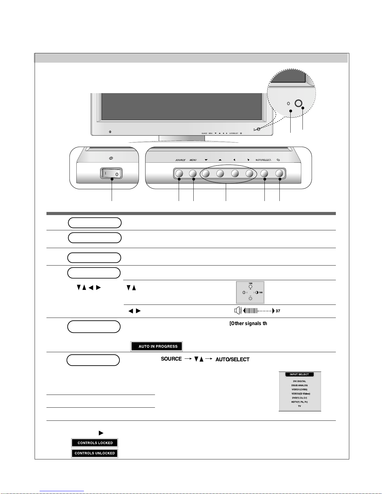
OPERATING INSTRUCTIONS
Front Control Panel
MAIN
MAIN
7
2
1568 3 4
• Press the button to turn on the power. Press the button again to turn it off.
• The power LED will be on when power is on.
Power Button
Power (DPMS)
Indicator
Adjust the volume
•
Adjust brightness and contrast.
Press the Menu button to hide
the screen
• Use this button toshow/hide the OSD(on Screen Display) menu screen.
MENU Button
•
Use the button to select an icon or adjust the setting in the OSD screen .
OSD
Buttons
[For DSUB signal]
•Select the icon to adjust on the OSD screen.
•If you press the [AUTO/SELECT] button,
automatic screen adjustment will be started.
AUTO/SELECT Button
1
2
3
4
5
6
8
7
This function allows you to secure the current control settings, so that they cannot be
inadvertently changed. Press and hold the MENU button and right button for 3 seconds:
the message “CONTROLS LOCKED” appears.
You can unlock the OSD controls at any time by pushing the MENU button and right
button for 3 seconds:
the message “CONTROLS UNLOCKED” will appear.
•
Use this button to select an input signal.
• DVI DIGITAL: DVI digital signal
• DSUB ANALOG: 15-pin D-sub analog signal
• VIDEO1 (CVBS): Composite video
• VIDEO2 (S-Video): S-video
• DVD(Y, Cb, Cr): DVD
• HDTV(Y, Pb, Pr): HD television
• TV: television -L3020T(Option)
SOURCE
Button
CONTROLS LOCKED/UNLOCKED :
MENU and
Remote Control Sensor
Power On/Off switch
AUTO/SELECT
SOURCE
[Other signals that DSUB]
•The current signal and mode information will
be displayed.
- 8 -
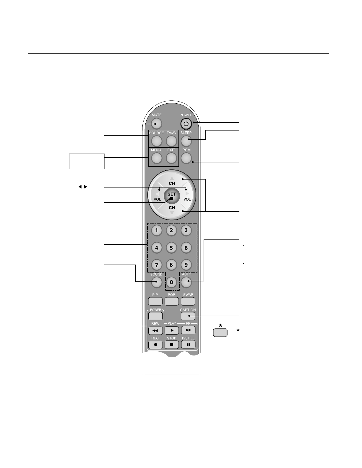
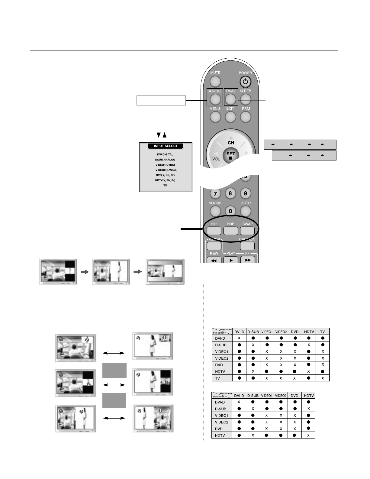
Remote Controller Buttons
Power On/Off Button
Channel Up/Down Button
•
Input Select Button
•
TV/AV Button
(See next page)
Sleep Button
When watching AV/DVD/HDTV/TV(L3020T)
AV/DVD/HDTV(L3020A)
-
The monitor will be automatically turned off
after a certain period of time.
Press this button repetitively to select an
appropriate time duration
PSM Button
When watching AV/DVD/HDTV/TV(L3020T)
AV/DVD/HDTV(L3020A)
- Automatically adjusts the image.
Press this button repetitively to set the
intended screen.
CAPTION Button
- L3020T(Only U.S.A)
There is not a function
which is supported
- L3020A
•
Menu Button
•
Exit Button
Auto Channel Button
TV: Automatic TV channel setup
(Applicable to the model equipped
with the TV tuner) - (Option)L3020T
PC: Automatic adjustment function
(Operational for the analog signal only)
Channel Number Select
Button
Operational at the TV mode only
Check Button
Sound Mode Select
Select the sound mode
: MONO/STEREO/SAP-(Only U.S.A)
MONO/STEREO-AV
Video Operation Button
Applicable for LG products only
Volume Button
Mute button
- 9 -
1. PIP (Picture in Picture) Button
The sub-screen moves to the next mode whenever you press this button.
: Small -> Large -> Off
2. POP (Picture out Picture) Button
The sub-screen moves to the next mode whenever you press this button.
: POP ON -> PBP(FULL) -> PBP(4:3) -> OFF
If you press the button once,
the following Input Signal
Window will appear. Select
the signal type you want
using the button.
This button will be enabled only
when you selected the TV/AV
signal. The signal type will be
changed with the following order.
Set the signal type you want.
POP ON PBP (FULL) PBP (4:3)
•
Input Select Button
•
TV/AV Button
3. Swap Button
You can swap the main screen and the sub-screen when the PIP/POP/PBP
function is used..
When 'Input Signal 1' comes on in the main screen, only
'Input Signal 2' can be displayed on the sub-screen. On the
contrary, if the main screen displays 'Input Signal 2', the subscreen can display 'Input Signal 1' only. You can swap 'Input
Signal 1' and 'Input Signal 2' using the SWAP button.
<Table of PIP/POP/PBP Function Support> -L3020T
<Table of PIP/POP/PBP Function Support> -L3020A
TV VIDEO1 VEDIO2 DVD HDTV
VIDEO1 VEDIO2 DVD HDTV
SWAP
SWAP
PIP
POP
PBP
AV
- 10 -
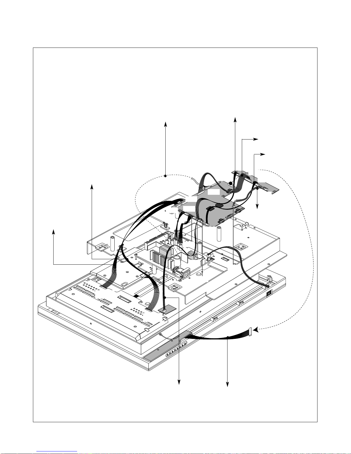
WIRING DIAGRAM(LPL Module)
CN1
CN1
J503
J506
J602
J108
J601
J604
J605
J401
J402
J201
J505
J801
J802
J803
J804
Connector Ass’y P/N:
6631T11016A
Connector Ass’y P/N:
6631T20029C
Connector Ass’y P/N:
6631T20028D
Connector Ass’y P/N:
6631T20028C
Connector Ass’y P/N:
6631T12002P
Connector Ass’y P/N:
6631T12002N
Connector Ass’y P/N:
6631T20029B
Connector Ass’y P/N:
6631T20028E
Connector Ass’y P/N:
6631T20028B
- 11 -
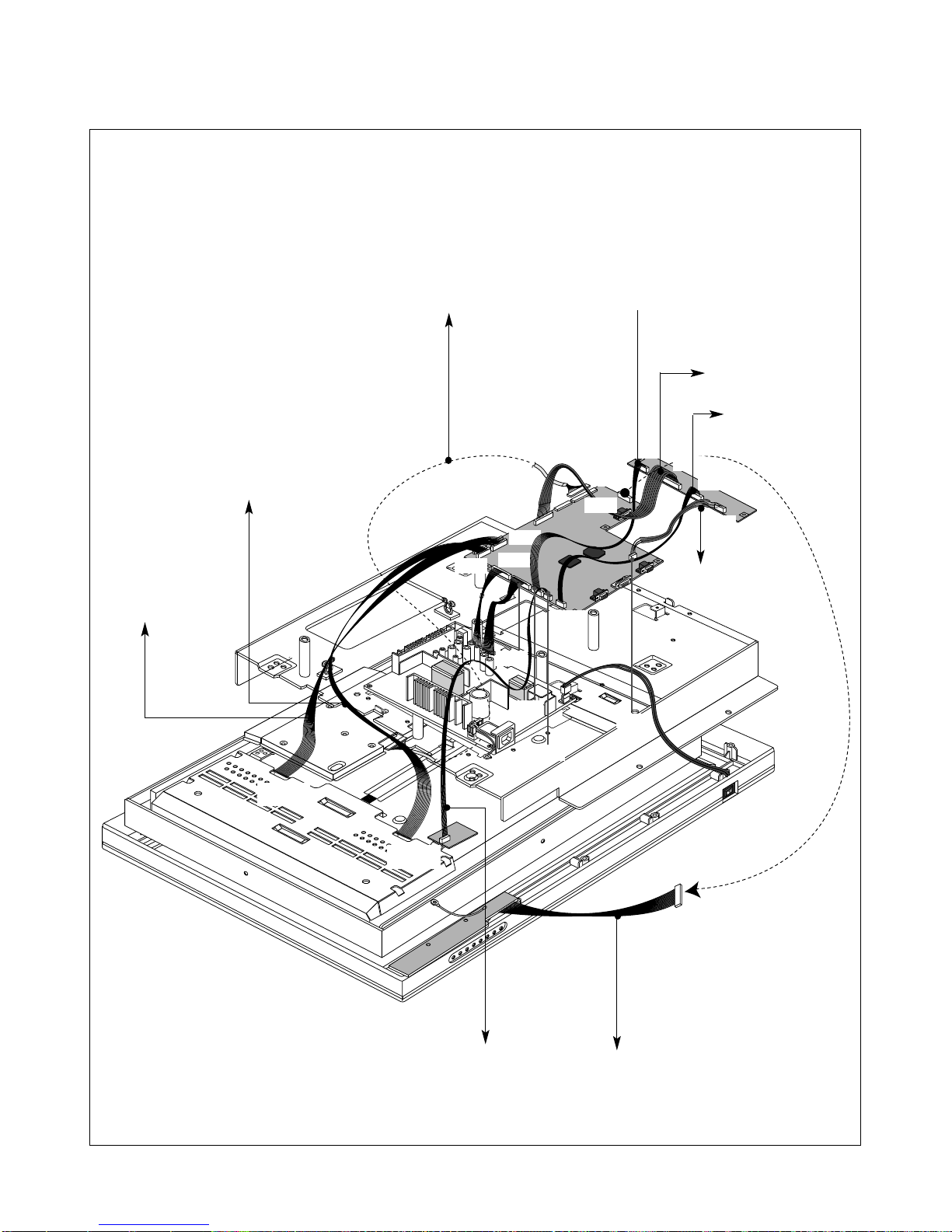
WIRING DIAGRAM(CMO Module)
CN1
CN1
J503
J506
J602
J108
J601
J606
J607
J402
J201
J505
J801
J802
J803
J804
J403
Connector Ass’y P/N:
6631T11016K
Connector Ass’y P/N:
6631T20029C
Connector Ass’y P/N:
6631T20028E
Connector Ass’y P/N:
6631T20028B
Connector Ass’y P/N:
6631T20028D
Connector Ass’y P/N:
6631T20028C
Connector Ass’y P/N:
6631T20020T
Connector Ass’y P/N:
6631T120020S
Connector Ass’y P/N:
6631T20029B

- 12 -
DDR
BLOCK DIAGRAM
128Mb
Video Signal
SDRAM
3.3V
(HY5DU283222Q4)
(29LV040B)
Memory
4Mb Flash
LCD
Module
Even
R,G,B
1.8V
2.5V
3.3V
5V
12V
24V
DC/DC
Regulator
(CMO)
(LPL)
5V
12V
Power
Built-in
Format Converter
2.5V
Circuit
Data
(FSD 0 ..31)
(FSA 0 ..11)
3.3V
2.5V
1.8V
DDC-A
EEPROM
DDC-D
EEPROM
H/ V Sync
Digital Signal
Data
(OCMD 0 ..7)
(OCMA 0 ..19)
(gm1501)
Processor
Video Signal
24Bit
Analog Signal
INV_PWR
LCM_PWR
AMP_PWR
PCB_PWR
System
EEPROM
(FLI2310)
Deinterlacer
64Mb
SDRAM
(HY57V643220)
Control Signals
16 Bit
YUV
Only USA
PCB_PWR
INV_PWR
Caption/V-Chip
Video
Decoder
LCM_PWR
AMP_PWR
12V
(M37136)
Video Out
(VPC3230)
Video Filter(5.2Mhz)
CVBS PAL
CVBS Out
8V
Audio
Amp
(TPA3004D2)
Audio
Decoder
SP (R)
TPA6110
VAROUTR/L
(MSP3420G)
Switch
Analog
H/ V Sync
RGB
D VI-D
D-SUB
(BA7657F)
YPbPr
HDTV
RXD
TXD
MAX232C
Port
Serial
DVD
Y/Cb/Cr
Y-out
C-out
CVBS 1
CVBS 2(Tuner)
S/W
(CXA2040AQ)
Y/C-in
Filter
Y/C-out
(UPD64083)
3D Comb
CVBS Audio
CVBS Out
Out
DTV Audio
DVD Audio
CVBS Audio
PC Audio

- 13 -
DESCRIPTION OF BLOCK DIAGRAM
1. Input Selection Circuit
1) Analog Input Selection
This block is composed of BA7657F(U103) and
peripheral devices.
There are analog H/V Syncs. BA7657F IC chooses one
input and outputs selected input through sync selection
pin (Pin 1).
2) Video Input Selection
This block is composed of video S/W IC (CXA2040Q,
U3) and peripheral devices. There are three inputs in
CXA2040Q IC(CVBS video signal through RF tuner,
video input CVBS, S-video signal). One selected video
signal is transmitted a video decoder IC (VPC3230, U1)
2. DDC controller
This block is composed of GM1501(U402) and
peripheral EEPROM IC(U107,U108).
GM1501(U402) controls peripheral devices through IIC
line.
Major functions are (1) to control Flash memory
through DDC-SCLA, DDC-SDAA of D-sub and (2) to
store EDID data in the EEPROM (U107,U108).
3. Video Decoder
This block is composed of VPC 3230 (U1) and
peripheral devices.
GM 1501 controls this IC through IIC Line.
This IC analyzes input signal of CVBS, Y/C and output
analyzed signal (8bit interlace signal) to De-interlace
block.
Analyzed signal has video control signals like Contrast,
Brightness, Sharpness, Color, tint signals Including
Adaptive Comb Filter.
4. Audio Decoder
This block is composed of MSP3420G (U503) and
peripheral devices.
GM 1501 controls this IC through IIC Line.
This IC analyzes audio input signal through A/V Jack
and PC audio.
The analyzed signals transmitted to audio amplifier
(TPA3004, U505).
5. Audio Amplifier
This block is composed of TPA3004 (U505) and
peripheral devices.
The function of the audio amplifier is that to amplify
audio L/R signal transmitted from audio decoder. The
audio signal is amplified according to pre-defined DC
volume control curve. Also, Headphone
amplifier(Tpa6110, U501) is controlled through Lineout.
6. De-interlacer
This block is composed of FLI 2310(U301) and
peripheral devices.
GM1501 (U402) controls this IC through IIC Line.
And this IC converts 8 Bit Interlaced Y/UV signal to Deinterlaced signal.
It output converted signal to Format Converter IC(GM
1501, U402).
7. Format Converter
This block is composed of GM 1501(U402) and
peripheral devices. GM 1501(Scaler,U402) contains
MICOM.
1) This IC contain A/D converter, Pre-amp and PLL
circuit that converting analog video signal(0.7Vp-p)
through D-sub(J103) Pin to digital signal.
2) This IC Decode TMDS signals of 8 line from DVI-D
Pin (J202) and transmit to LVDS Transmitter.
GM 1501 is Format Converter IC that receives Digital
signal and outputs proper frame signal to LCD Module
Timing(1280x768,WXGA).
8. DC/DC Converter block
DC/DC Converter convert the input 12V, 24V to proper
2.5V, 3.3V, 5V, 1.8V for main control system.
For shooting heat trouble, we use the DC/DC
converting IC.
9. Caption/V-CHIP block -Only U.S.A
This block is composed of M37136(U202) and
peripheral devices. M37136 IC is useful for channel
selection system for TV with a closed caption decoder.
It receives text information signal and displays text
information through text receiver decoder. It called
multi-text broadcast.
10. Power Supply Block
This Block generates DC Voltages(12V, 24V) to Main
Control system from AC Power(100-240 V, 50/60 Hz,
1.0 A).
This Circuit contains PFC(Power Factor correction)
circuit.
The Minimum of Power efficiency is about 75%.
- 14 -
ADJUSTMENT
All adjustment are thoroughly checked and corrected
when the monitor leaves the factory, but sometimes
several minor adjustment may be required.
Adjustment should be following procedure and after
warming up for a minimum of 30 minutes.
• Alignment appliances and tools.
- IBM compatible PC
- Programmable Signal Generator.
(eg. VG-819 made by Astrodesign Co.)
- Oscilloscope.
- White Balance Meter. (CA-110)
1. Adjustment Start
1) Display any pattern at any Mode.
2) Run alignment program for L3020AL on the IBM
compatible PC.
3) Select EEPROM → ALL INIT command and Enter.
4) This will make all data to default state.
5) Select COMMAND → PRESET START command
and Enter.
2. DDC Data Write Procedure-Analog
1) Use this procedure only when there is some
problem on Analog EDID data.
2) Run alignment program for L3020AL on the IBM
compatible PC.
3) Select EEPROM → Analog EDID write command
and Enter.
4) This will write the Analog EDID data to EEPROM.
3. DDC Data Write Procedure-Digital
1) Use this procedure only when there is some
problem on Digital EDID data.
2) Run alignment program for L3020AL on the IBM
compatible PC.
3) Select EEPROM → Digital EDID write command
and Enter.
4) This will write the Digital EDID data to EEPROM.
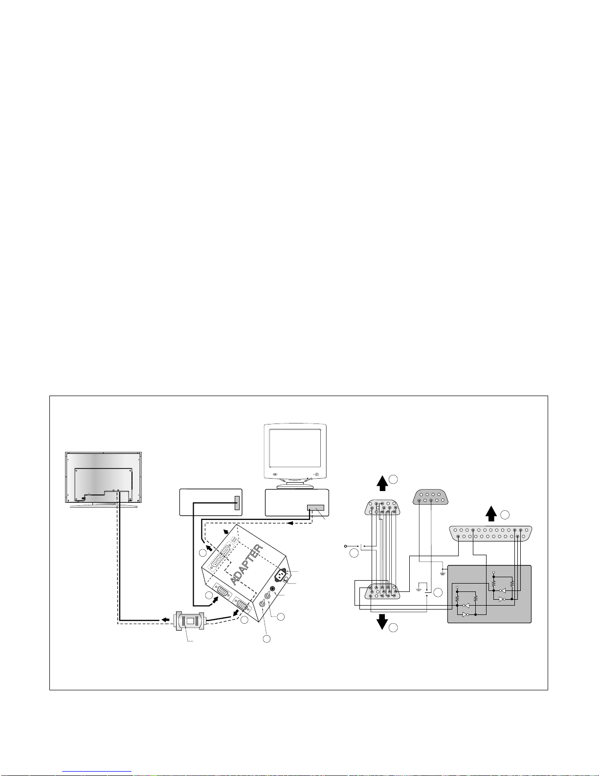
DVI-D Connector
RS-232C
EXT.
220
IBM
Compatible PC
Parallel Port
Power inlet (required)
Power LED
ST Switch
Power Select Switch
(110V/220V)
Control Line
Not used
RS232C
PARALLEL
V-SYNC
POWER
ST
VGS
MONITOR
E
V-Sync On/Off Switch
(Switch must be ON.)
F
A
B
C
5V
E
F
A
B
C
15
10
5
5
69
1
1
1
14
13
25
6
5V
5V
4.7K
4.7K
4.7K
74LS06
74LS06
OFF ON
OFF
ON
11
Figure 1. Cable Connection
 Loading...