

LG FLATRON L1810T, FLATRON L1810A, LM805L-WL Service Manual
COLOR MONIT OR
SER VICE MANUAL
CHASSIS NO. : CL-36
F ACTORY MODEL: LM805L
MODEL: L1810T (LM805L-WL)
L1810A (LM805L-WL)
CAUTION
BEFORE SERVICING THE UNIT,
READ THE SAFETY PRECAUTIONS IN THIS MANUAL.
1. LCD CHARACTERISTICS
Type : TFT Color LCD Module
Size : 18.1inch
Pixel Pitch : 0.2805(H) x 0.2805(V)
Color Depth : 8-bit, 16,777,216 colors
Electrical Interface : LVDS
Surface Treatment : Anti-Glare, Hard Coating(3H)
Operating Mode : Normally Black
Backlight Unit : Six-CCFL (Cold Cathode
Fluorescent Lamp)
2. OPTICAL CHARACTERISTICS
2-1. Viewing Angle by Contrast Ratio
≥
10
Left : -60° min., -80°(Typ)
Right : +60° min., +80°(Typ)
Top : +60° min., +80°(Typ)
Bottom : -60° min., -80°(Typ)
2-2. Luminance : 200(min), 250(Typ)
2-3. Contrast Ratio : 200(min), 300(Typ)
3. SIGNAL (Refer to the Timing Chart)
3-1. Video Input
1)Signal Input : 15pin D-sub Connector/
DVI-D Connector
2)Input Form : Separate, RGB Analog, 0.7Vp-p/
75 Ω, Positive Digital
3) Resolution(max) : Analog -1280 x 1024
@75Hz
Digital -1280 x 1024@60Hz
3-2. Audio Signal
1) Input: PC : 700mVrms
VCR: 400mVrms
2)
Audio Output and its ratio:
PC : 1W+1W/ 3%
VCR: 1W+1W/ 3%
3) Speaker Impedance : 8 Ω
3-3. Sync Input
Horizontal : 30 ~ 83kHz
Vertical : 56 ~ 85Hz
Input Form : Separate, TTL,
Positive/Negative Digital
4. POWER SUPPLY
4-1. Power Adaptor
Input : AC 100~240V, 50/60Hz , 1.5A
Output : DC 12V 5A
4-2. Power Consumption
5. ENVIRONMENT
6-1. Operating Temperature: 10°C~35°C (50°F~95°F)
(Ambient)
6-2. Relative Humidity : 10%~80%
(Non-condensing)
6-3. MTBF : 30,000 Hours(Typ.)
6. DIMENSIONS (with TILT/SWIVEL)
Width : 406 mm (15.98'')
Depth : 223 mm (8.78')
Height : 431 mm (16.97'')
7. WEIGHT (with TILT/SWIVEL)
Net. Weight : 8.0kg (17.64 lbs)
Gross Weight : 10.5kg (23.15 lbs)
8. USB
USB standard :
Rev.1.0compliedSelf-poweredhub
Downstream power supply
: 500mA for each(MAX)
Communication speed : Full-12Mbps, Low-1.5Mbps
USB port : 1 Upstream port
2Downstream ports
9. Audio
RMS Audio Output : 1W + 1W(R+L)/10%
Input Sensitivity : 0.700Vrms
Speaker Impedance : 8
Ω
CONTENTS
SPECIFICATIONS
- 2 -
SPECIFICATIONS ................................................... 2
PRECAUTIONS ....................................................... 4
TIMING CHART ....................................................... 5
OPERATING INSTRUCTIONS ................................ 6
WIRING DIAGRAM ............................................... 10
BLOCK DIAGRAM ................................................. 11
DESCRIPTION OF BLOCK DIAGRAM...................13
ADJUSTMENT ...................................................... 15
TROUBLESHOOTING GUIDE .............................. 16
PRINTED CIRCUIT BOARD................................... 22
EXPLODED VIEW...................................................25
REPLACEMENT PARTS LIST ...............................27
PIN CONFIGURATION............................................35
SCHEMATIC DIAGRAM......................................... 39
MODE
POWER ON (NORMAL)
STAND-BY
SUSPEND
DPM OFF
POWER OFF
H/V SYNC
ON/ON
OFF/ON
ON/OFF
OFF/OFF
-
POWER CONSUMPTION
less than 60 W
less than 5 W
less than 5 W
less than 5 W
less than 5 W
LED COLOR
GREEN
AMBER
AMBER
AMBER
OFF
VIDEO
ACTIVE
OFF
OFF
OFF
-
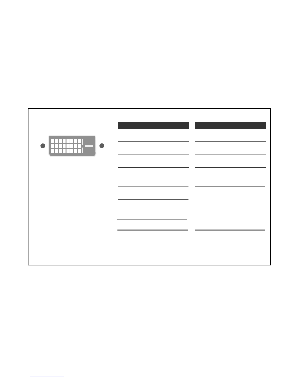
Signal Connector Pin Assignment
Pin Signal (DVI-D)
1
2
3
4
5
6
7
8
9
10
11
12
13
14
15
T. M. D. S. Data2T. M. D. S. Data2+
T. M. D. S. Data2/4 Shield
T. M. D. S. Data4T. M. D. S. Data4+
DDC Clock
DDC Data
Analog Vertical Sync.
T. M. D. S. Data1T. M. D. S. Data1+
T. M. D. S. Data1/3 Shield
T. M. D. S. Data3T. M. D. S. Data3+
+5V Power
Ground
(return for +5V,
H. Sync. and V. Sync.)
Pin Signal (DVI-D)
1
8
9
17
24
16
16
17
18
19
20
21
22
23
24
Hot Plug Detect
T. M. D. S. Data0T. M. D. S. Data0+
T. M. D. S. Data0/5 Shield
T. M. D. S. Data5T. M. D. S. Data5+
T. M. D. S. Clock Shield
T. M. D. S. Clock+
T. M. D. S. Clock-
T. M. D. S. (Transition Minimized Differential Signaling)
• DVI-D Connector (Digital)
- 4 -
WARNING FOR THE SAFETY-RELATED COMPONENT.
• There are some special components used in LCD
monitor that are important for safety. These parts are
marked on the schematic diagram and the
replacement parts list. It is essential that these critical
parts should be replaced with the manufacturer’s
specified parts to prevent electric shock, fire or other
hazard.
• Do not modify original design without obtaining written
permission from manufacturer or you will void the
original parts and labor guarantee.
TAKE CARE DURING HANDLING THE LCD MODULE
WITH BACKLIGHT UNIT.
• Must mount the module using mounting holes arranged
in four corners.
• Do not press on the panel, edge of the frame strongly
or electric shock as this will result in damage to the
screen.
• Do not scratch or press on the panel with any sharp
objects, such as pencil or pen as this may result in
damage to the panel.
• Protect the module from the ESD as it may damage the
electronic circuit (C-MOS).
• Make certain that treatment person’s body are
grounded through wrist band.
• Do not leave the module in high temperature and in
areas of high humidity for a long time.
• The module not be exposed to the direct sunlight.
• Avoid contact with water as it may a short circuit within
the module.
• If the surface of panel become dirty, please wipe it off
with a softmaterial. (Cleaning with a dirty or rough cloth
may damage the panel.)
WARNING
BE CAREFUL ELECTRIC SHOCK !
• If you want to replace with the new backlight (CCFL) or
inverter circuit, must disconnect the AC adapter
because high voltage appears at inverter circuit about
650Vrms.
• Handle with care wires or connectors of the inverter
circuit. If the wires are pressed cause short and may
burn or take fire.
PRECAUTION
CAUTION
Please use only a plastic screwdriver to protect yourself
from shock hazard during service operation.
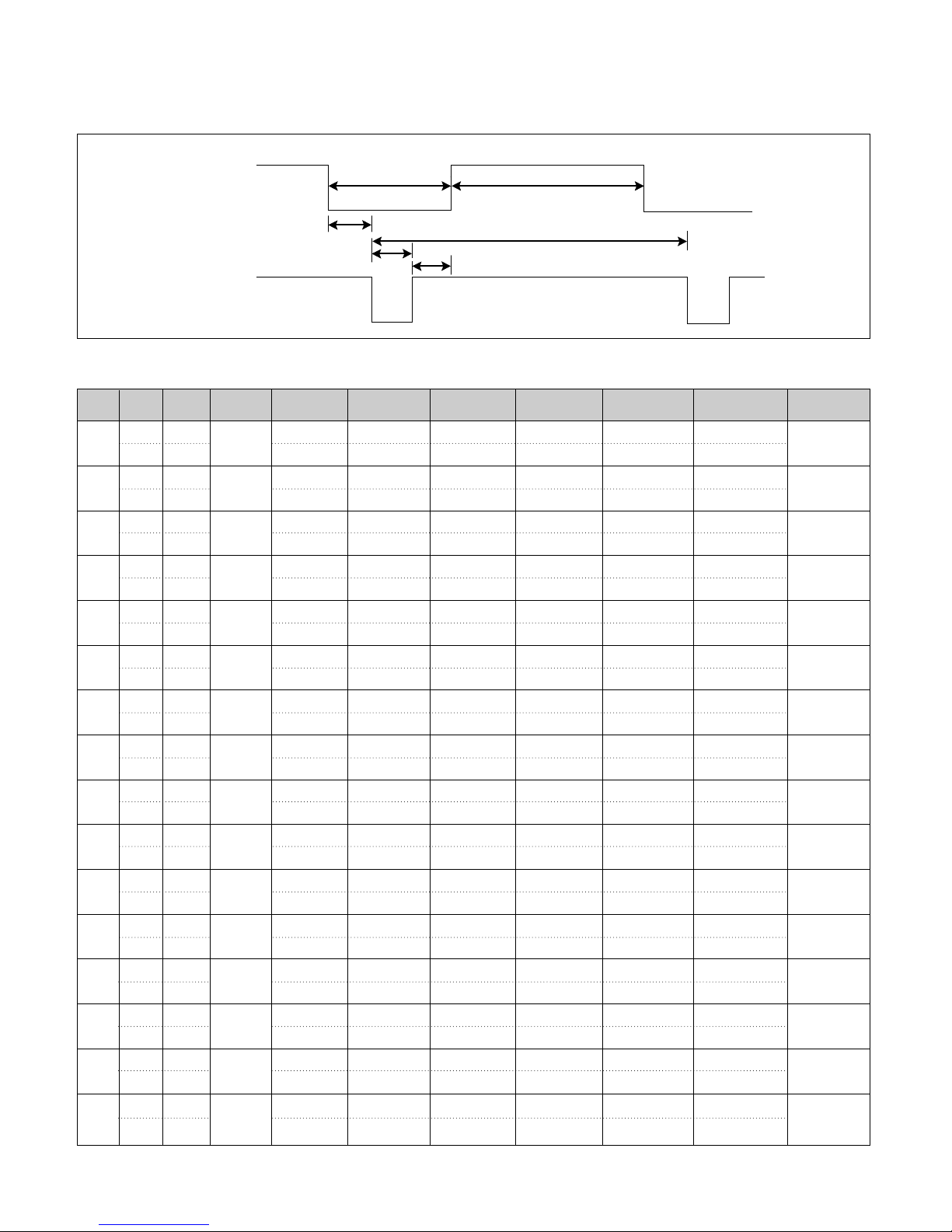
TIMING CHART
- 5 -
VIDEO
SYNC
B
D
C
F
E
A
<< Dot Clock (MHz), Horizontal Frequency (kHz), Vertical Frequency (Hz), Horizontal etc... (µs), Vertical etc... (ms) >>
H + 31.469 800 640 16 96 48
V – 70.8 449 350 37 2 60
H – 43.269 832 640 56 56 80
V – 85.0 509 480 1 3 25
H – 31.469 800 640 16 96 48
V – 59.94 525 480 10 2 33
H – 37.5 840 640 16 64 120
V – 75 500 480 1 3 16
H – 31.468 900 720 18 108 54
V + 70.8 449 400 12 2 35
H + 37.879 1056 800 40 128 88
V + 60.317 628 600 1 4 23
H + 46.875 1056 800 16 80 160
V + 75.0 625 600 1 3 21
H + 53.674 1048 800 32 64 152
V + 85.061 631 600 1 3 27
H+/– 49.725 1152 832 32 64 224
V+/– 74.55 667 624 1 3 39
H – 48.363 1344 1024 24 136 160
V – 60.0 806 768 3 6 29
H – 60.123 1312 1024 16 96 176
V – 75.029 800 768 1 3 28
H + 68.677 1376 1024 48 96 208
V + 84.997 808 768 1 3 36
H+/– 68.681 1456 1152 32 128 144
V+/– 75.062 915 870 3 3 39
H+/– 61.805 1504 1125 18 134 200
V+/– 65.96 937 900 2 4 31
H + 63.981 1688 1280 48 112 248
V + 60.02 1066 1024 1 3 38
H + 79.976 1688 1280 16 144 248
V + 75.035 1066 1024 1 3 38
Mode
H/V
Sort
1
2
3
4
5
6
7
8
9
10
11
12
13
14
15
16
25.175
28.321
25.175
31.5
36.0
40.0
49.5
56.25
57.283
65.0
78.75
94.5
100.0
92.978
108.0
135.0
640x350
70Hz
640x480
85Hz
640x480
60Hz
640x480
75Hz
720x400
70Hz
800x600
60Hz
800x600
75Hz
800x600
85Hz
832x624
75Hz
1024x768
60Hz
1024x768
75Hz
1024x768
85Hz
1152x870
75Hz
1152x900
65Hz
1280x1024
60Hz
1280x1024
75Hz
Sync
Polarity
Frequency
Dot
Clock
Total Period
(E)
Video Active Time
(A)
Sync Duration
(D)
Back Porch
(F)
Front Porch
(C)
Resolution
OPERATING INSTRUCTIONS
SOURCE MENU
AUTO/SELECTPR.
PIP
VOL.
37
100
100
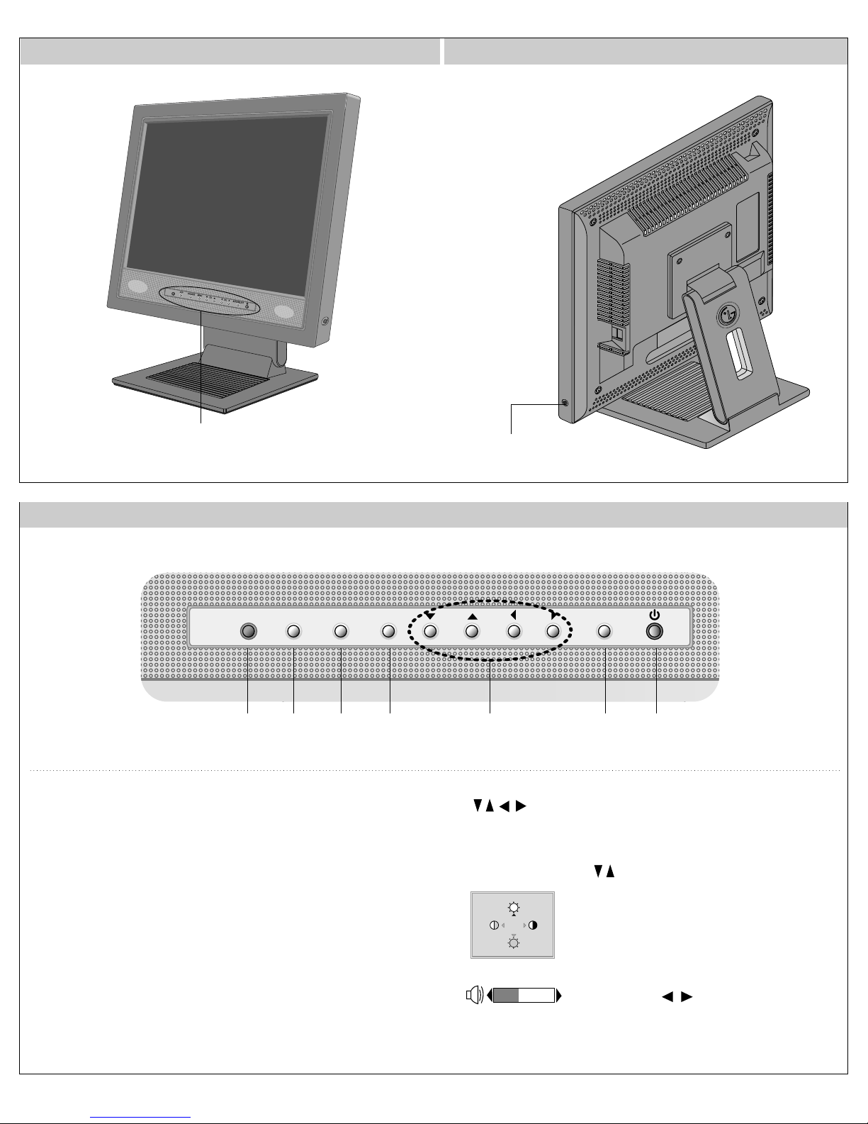
FRONT VIEW
Front Control Panel
SIDE VIEW
Headphone/
Earphone Input
Front Control Panel
67 5 2 3 4 1
1. Power Button
Use this button to turn the display on or off.
<Power (DPMS) Indicator>
This Indicator lights up green when the display
operates normally. If the display is in DPM (Energy
Saving) mode, this indicator color changes to
amber.
2. Menu Button
Use this button to enter or exit the On Screen
Display.
3. Button
Use these buttons to choose or adjust items in the
On Screen Display.
•
Bring up Contrast and Brightness
adjustment.
• Use these buttons to go up and
down the programned channel
when the TV source is available.
Volume:
Use these buttons to decrease or increase the
volume level
.
4. AUTO/
SELECT Button
Use this button to enter a selection in the On
Screen Display.
AUTO adjustment function
5. Source Selection
Button
Use this button to enter a selection in the On
Screen Display.
6. PIP(Picture in Picture) function
7. Remote Control Sensor
※ CONTROLS LOCKED/UNLOCKED
:
MENU and Button
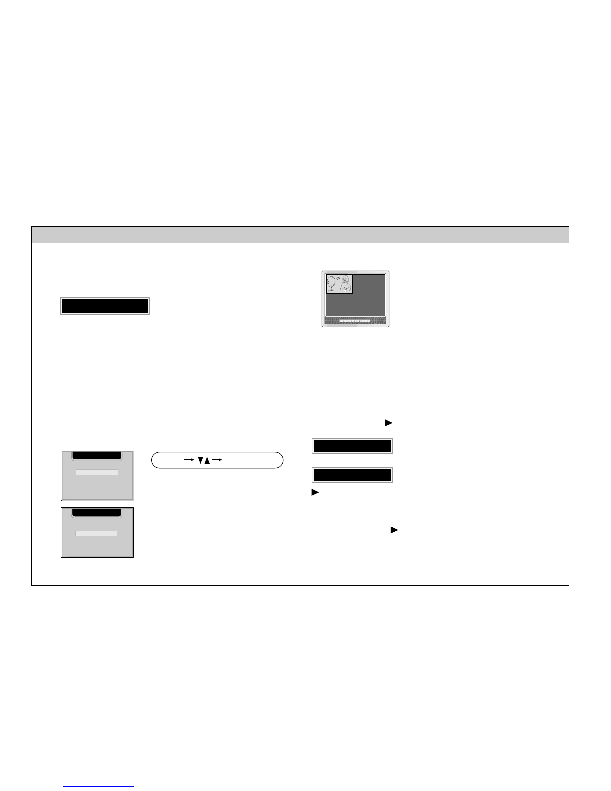
OPERATING INSTRUCTIONS
Front Control Panel
AUTO IN PROGRESS
When adjusting your display settings, always press the
AUTO/SELECT button before entering the On Screen
Display(OSD). This will automatically adjust your display
image to the ideal settings for the current screen
resolution size (display mode).
The best display mode is 1280x1024.
This PIP (Picture-in-Picture) function
allows the image from the TV
(HDTV), VCR or DVD to be
displayed on a sub-screen while you
are using a computer.
The sub-screen is changed in the order shown below.
: SMALL -> LARGE -> OFF
INPUT MENU
AUTO/SELECT
PIP
INPUT SELECT
DVI DIGITAL
V1 (AV)
V2 (S)
DSUB ANALOG
INPUT SELECT
DVI DIGITAL
V1 (AV)
V2 (S)
DSUB ANALOG
TV
AUTO/SELECT
INPUT
Use this button to select an input
signal.
• DVI DIGITAL: DVI digital signal
• DSUB ANALOG: 15-pin D-sub
analog signal
• TV: TV
• V1(AV): Composite video
• V2(S): S video
*
When the TV source is available.
This function allows you to secure the
current control settings, so that they
cannot be inadvertently changed.
Press and hold the MENU button and
button for 3 seconds: the message “CONTROLS
LOCKED” appears.
You can unlock the OSD controls at any time by pushing the
MENU button and button for 3 seconds:
the message “CONTROLS UNLOCKED” will appear.
CONTROLS LOCKED
CONTROLS UNLOCKED
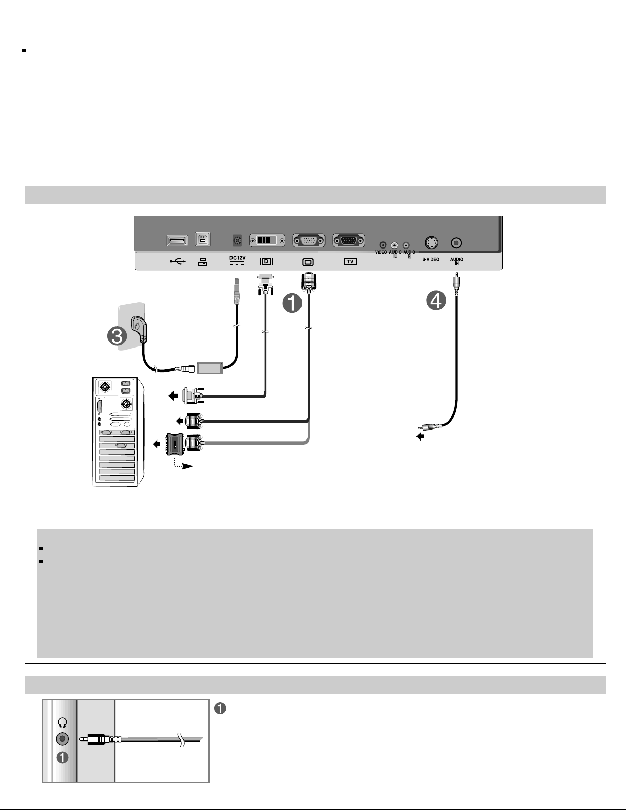
Connecting the Display
Before setting up the monitor , ensure that the power to the monitor, the computer system, and other
attached devices is turned off.
Using the Computer
1. Connect the signal cable. When attached, tighten the thumbscrews to secure the connection.
2. Connect the plug from the AC adapter into the back of the monitor.
3. Connect the power cord into a proper power outlet that is easily accessible and close to the display.
4. Connect the audio cable to the *LINE OUT jack of the PC sound card.
REAR VIEW(Bottom)
PC
PC
MAC
NOTE
Mac adapter
For Apple Macintosh use, a separate plug adapter is needed to
change the 15 pin high density (3 row) D-sub VGA connector
on the supplied cable to a 15 pin 2 row connector.
This is a simplified representation of the rear view.
This rear view represents a general model; your display may differ from the view as shown.
*LINE OUT
A terminal used to connect to the speaker including a built-in amplifier (Amp). Make sure that
the connecting terminal of the PC sound card is checked before connecting. If the Audio Out of
PC sound card has only Speaker Out, reduce the PC volume.
If the Audio Out of the PC sound card supports both Speaker Out and Line Out, convert to Line Out using the card jumper of the program
(Refer to the Sound Card Manual).
SIDE JACK
Headphone/Earphone Input
Automatically mutes the speaker volume
when the headphones are plugged in.
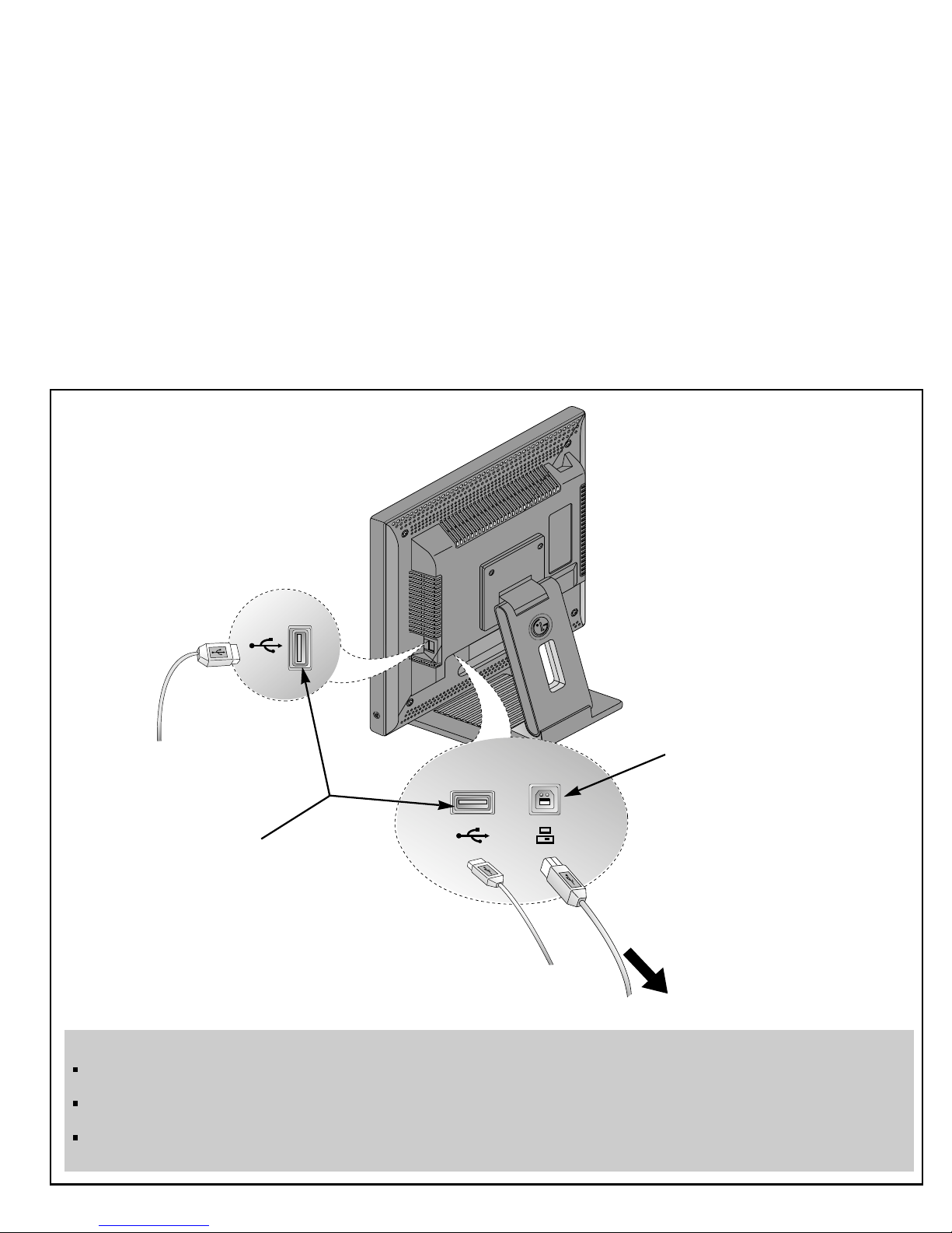
Making use of USB (Universal Serial Bus)*
USB (Universal Serial Bus) is an innovation in connecting your different desktop peripherals conveniently to your computer.
By using the USB, you will be able to connect your mouse, keyboard, and other to your monitor instead of having to
connect them to your computer. This will give you greater flexibility in setting up your system. USB allows you to connect
chain up to 120 devices on a single USB port, and you can “hot” plug (attach them while the computer is running) or unplug
them while maintaining Plug and Plug auto detection and configuration. This monitor has an integrated BUS-powered USB
hub, allowing up to 2 other USB devices to be attached it.
USB connection
1. Connect the upstream port of the Display to the downstream port of the USB compliant PC or another hub using the
USB cable. (Computer must have a USB port)
2. Connect the USB compliant peripherals to the downstream ports of the monitor.
USB upstream Port
USB downstream Port
connect the cables from USB
compliant peripherals-such as
keyboard, mouse, etc
To USB downstream port
of the USB compliant PC
or another hub cable
NOTE
To activate the USB hub function, the monitor must be connected to a USB compliant PC(OS) or another hub with the USB
cable(enclosed).
When connecting the USB cable, check that the shape of the connector at the cable side matches the shape at the connecting
side.
Even if the monitor is in a power saving mode, USB compliant devices will function when they are connected the USB ports(both
the upstream and downstream) of the monitor.
- 9 -
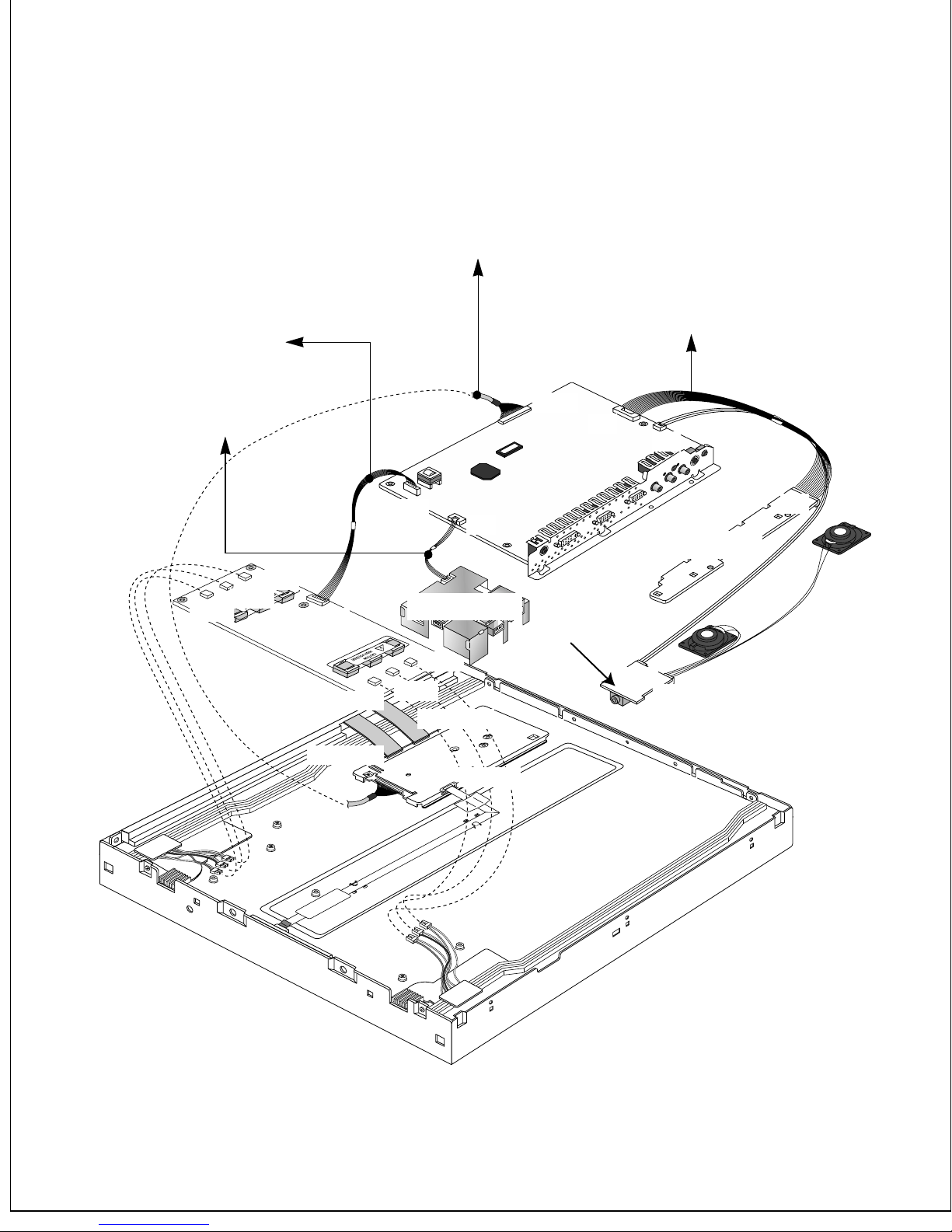
MODULE
CN1
CN4
CN5
CN6
CN7
CN8
CN9
CN_C01
CN301
CN_C02
J8
J4
J1
J10
J1
J710
J904
J901
USB Ass’y
CONTROL
AUDIO
MAIN
Connector Ass’y P/N:
6631T20015R
Connector Ass’y P/N:
6631T20020B
Connector Ass’y P/N:
6631T11012P
Connector Ass’y P/N:
6631T20020C

Key Control(15P)
Built-in
Speaker
Left
Built-in
Speaker
Right
(74
Multiplexer
LVC257A)
Audio AMP
Flash
Memory
(M29W800AT)
EEPROM
(24C16)
AD7823
DC/DC
Block
Audio
Processor
(MSP3410G)
EEPROM
(24C21)
EEPROM
(24C21)
L VDS
Transmitter
(63LVD823)
TMDS
Receiver
(Sil161B)
DVI-D
ADC
(AD9883KS
-140)
De-interlace
IC
Video
Decoder
(SAA7114H)
D-SUB(Male)
To
TV Tuner
Video Signal
Processor
(PW166B-20T)
D-SUB
Sync Separator
(BA7657)
Panel Link(30P)
4P
DC JACK
12V/ 5A
235 mm
Inverter
150 mm
Car Tuner
Main Assy
T uner Assy
SVHS
Comp.
Video
Audio
Right
Audio
Left
AV
PC
Audio Headphone
POWER
Menu
Set LED
Source
15pin contro l
PIP
CONTROL
DVI-D
D-SUB
CVBS
L
R
PC L/R
SP (R)
SP (L)
TMDS
Receiver
(SIL161A)
LVDS
Transmitter
LVD823)
Video
Decoder
(SAA7114)
Audio
Amp
(TDA7268)
Deinterlacer
(SDA
9400)
DC/DC
Converter
LCD
Module
12V
5V3.3V
12V_DC_Input
from Adapter
YUV
Flash
Memory
(M29W800DT)
EEPROM
8V
2.5V
Y/C
YUV
Multi-
plexer
(74LVC257)
H V Sync
H V Sync
GVS
GHS
Video Signal
GVS
GHS
Sync_Sel
Sync_Sel
3.3V
3.3V
3.3V
NCTL_SCL
NCTL_SDA
GREF
GREF
3.3V
5V
8V
12V
3.3V
3.3V
2.5V
3.3V
3.3V
12V
Control Board
Buffer
(74LVC541ct)
RDN CS0N
Data
(PWD ...07)
Key_Data
(0...7)
CS0N
RDN
CS1N
Data
(PWD 0 ..7)
(PWA 0 ..19)
ROMOE
ROMWE
ROMWE
ROMOE
I/O
(74LVC273D)
PCB_PWR
INV_PWR
LCM_PWR
AMP_PWR
Control Signals
TMDSTX_PDNN
TMDSRX_PDNN
R,G,B
Even
R,G,B
Odd
RGB
Digital
Signal
Even
Input Selection
Format Converter Circuit
Analog
Switch
(BA7657F)
Tuner CVBS
ADC
(AD9883-140)
Tuner SIF
Tuner
R,G,B
differential
Audio
Processor
(MSP3410G)
Video Signal
Processor
(PW166B-20T)
Odd
(THC63

- 13 -
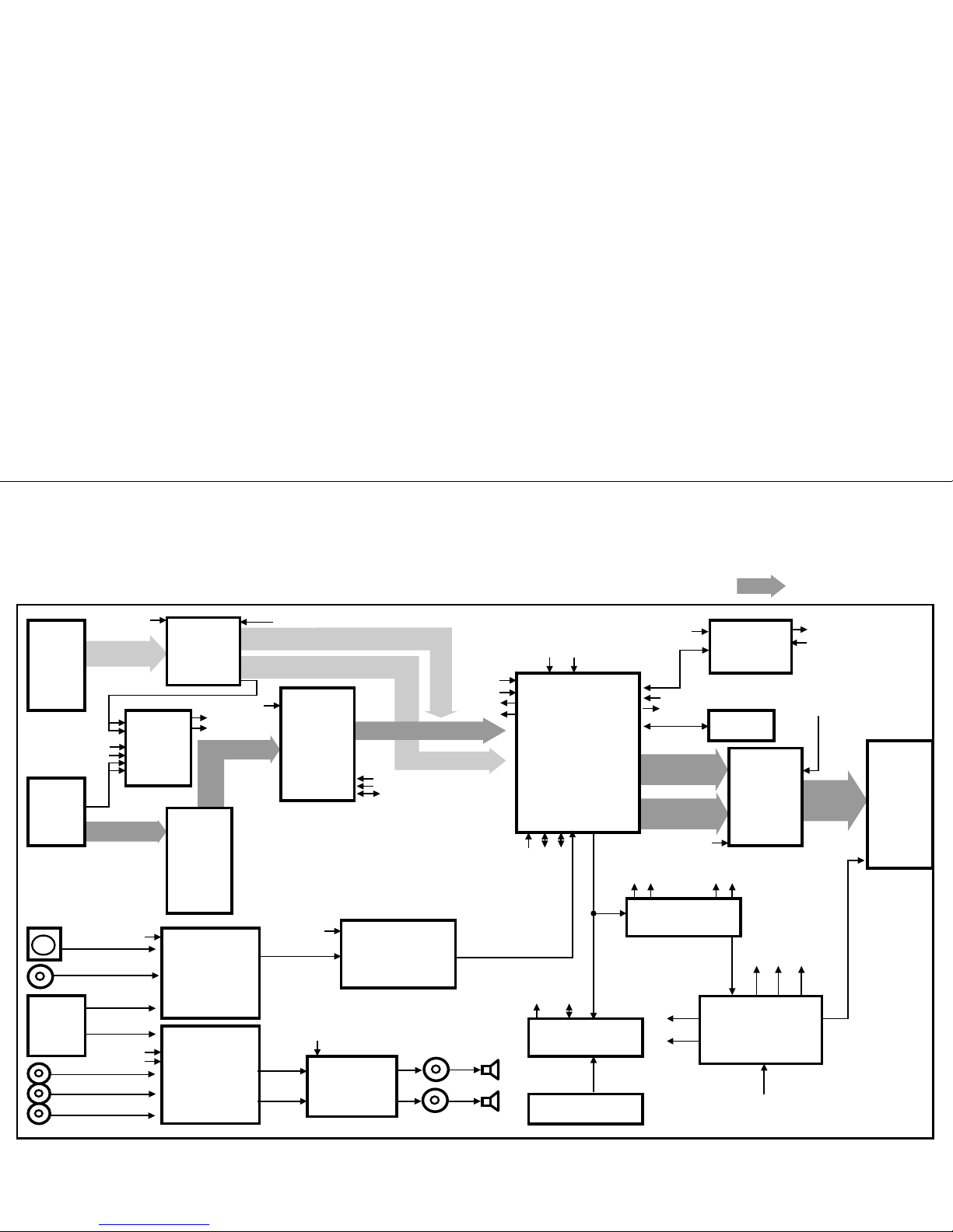
DESCRIPTION OF BLOCK DIAGRAM
1. Input Selection Circuit
This block is composed of 74LVC257(U5) and peripheral devices.
There are two inputs, Analog and Digital H/V Sync. LVC257 IC chooses one input and outputs selected input
through sync selection pin (Pin 1).
2. A/D Converter
This block is composed of AD9883 (U4) and peripheral devices.
AD9883 includes A/D converter, Pre-amp, and PLL.
The basic RGB signal (0.7Vp-p) is input to R,G,B pin of AD9883(U4).
Input video signal is amplified, Phase locked , A/D converted to 8bits digital signal by this IC(U4)
And send the Digital video signal to PW166B-20T.
U4 makes clock for PW166B-20T
3. TMDS Receiver
This Block is composed of SiI161B (U201) and peripheral devices.
This IC decodes Composite Input signal from DVI-D Pin (J18) and make 8bit digital signal to send
Digital EVEN/ODD signal to PW166B-20T.
4. DDC controller
This block is composed of PW166B-20T(U8) and peripheral devices.
PW166B-20T controls peripheral devices through IIC line.
Major functions are (1) to control Flash memory through DDC-SCLA, DDC-SDAA of D-sub
And (2) to store EDID data in the EEPROM (U17, U30)
5. Video Decoder
This block is composed of SAA7114H (U7) and peripheral devices.
PW166B-20T controls this IC through IIC Line.
This IC analyzes input signal of CVBS, Y/C and output analyzed signal (8bit interlace signal) to De-interlace block.
Analyzed signal has video control signals like Contrast, Brightness, Sharpness, Color, tint signals
Including Adaptive Comb Filter.
6. Audio Decoder
This block is composed of MSP3420G (U49) and peripheral devices.
PW166B-20T controls this IC through IIC Line.
This IC analyzes Audio input signal through A/V Jack and PC audio.
And output the analyzed signals to Audio Amplifier (TDA7268).
7. Audio Amplifier
This block is composed of TDA7268 (U39) and peripheral devices.
It amplifies audio signal input from Audio Decoder and output amplified audio signal to Speaker,
Audio Output Jack.
The output signal form is BTL.
8. De-interlacer
This block is composed of SDA9400 (U16) and peripheral devices.
PW166B-20T (U7) controls this IC through IIC Line.
And this IC convert 8 Bit Interlace Y/UV signal to De-interlace signal.
It output converted signal to Format Converter (PW166B-20T).
9. Format Converter
This block is composed of PW166B-20T (U8), M29W800DT (U19) and peripheral devices.
MICOM in PW166B-20T (U7) processes outputs of A/D Converter and TMDS Receiver,
De-interlace output and output processed 48 Bit Digital signal to TMDS Transmitter.
PW166B-20T is Format Converter IC that receive Digital signal and output proper frame signal to
LCD Module(1280x1024).

- 14 -
10. Panel-Link Circuit
TMDS Transmitter (THC63LVD273, U23) is the IC that receives output digital signal of PW166B-20T (U8) and
output to LCD Module.
The signal format is Panel-link.
LCD Module has Panel-link receiver that is same output of PW166B-20T.
This is the best for reduction EMI problem and the number of pin connector.
11. DC/DC Converter block
DC/DC Converters convert the input 12V to proper 2.5V, 3.3V, 5V, 8V for main board.
For shooting heat trouble, we use the DC/DC converting IC.
- 15 -
ADJUSTMENT
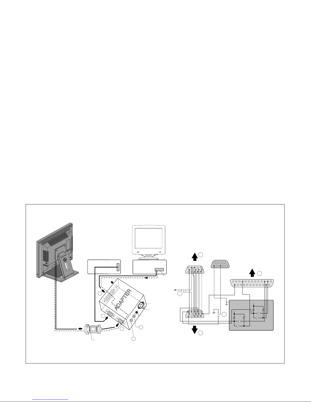
DVI-D Connector
220
IBM
Compatible PC
Parallel Port
Power inlet (required)
Power LED
ST Switch
Power Select Switch
(110V/220V)
Control Line
Not used
RS232C
PARALLEL
V-SYNC
POWER
ST
VGS
MONITOR
E
V-Sync On/Off Switch
(Switch must be ON.)
F
A
B
C
5V
E
F
A
B
C
15
10
5
5
69
1
1
1
14
13
25
6
5V
5V
4.7K
4.7K
4.7K
74LS06
74LS06
OFF ON
OFF
ON
11
Figure 1. Cable Connection
All adjustment are thoroughly checked and corrected
when the monitor leaves the factory, but sometimes
several minor adjustment may be required.
Adjustment should be following procedure and after
warming up for a minimum of 30 minutes.
• Alignment appliances and tools.
- IBM compatible PC
- Programmable Signal Generator.
(eg. VG-819 made by Astrodesign Co.)
- Oscilloscope.
- White Balance Meter. (CA-110)
1. Adjustment for Factory Preset Mode
No read to adjust FOS data for Factory Preset Mode.
2. Adjustment for White Balance
1) Set External Bright to MAX position and Contrast to
MAX position.
2) Display Color 0,0 pattern at Mode 15.
3) Press Menu key, Vp key, Right key of Remote
controller or Menu Buttons in sequence.
4) Select “WHITE BALANCE ADJUST” and Press SET
key.
5) After “INPUT WHITE PATTERN” message, Display
Color 15, 0 pattern at Mode 15.
6) No attempt to manually adjust, BIAS and Drive data
is automatically adjustde and saved to the EEPROM.
7) After “OK” message, Press SET KEY.
8) Select “SERVICE MODE EXIT” and Press SET KEY.
3. DDC Data Write Procedure-Analog
1) Use this procedure only when there is some
problem on Analog EDID data.
2) Run alignment program for LM805L on the IBM
compatible PC.
3) Select EEPROM
→ Analog EDID write command
and Enter.
4) This will write the Analog EDID data to EEPROM.
4. DDC Data Write Procedure-Digital
1) Use this procedure only when there is some
problem on Digital EDID data.
2) Run alignment program for LM805L on the IBM
compatible PC.
3) Select EEPROM → Digital EDID write command
and Enter.
4) This will write the Digital EDID data to EEPROM.
 Loading...