

Page 1

website : http://biz.lgservice.com
e-mail : http://LGEservice.com/techsup.html
WASHING MACHINE
SERVICE MANUAL
CAUTION
READ THIS MANUAL CAREFULLY TO DIAGNOSE PROBLEMS
CORRECT LY BEFORE OFFERING SE RVICE.
BEFORE SERVICING THE WASHING MACHINE, UNPLUG THE POWER
CORD TO AVOID THE RISK OF AN ELECTRIC SHOCK.
WHEN SERVICING INTERNAL PARTS, USE ONLY SERVICE PARTS
SUPPLIED FROM LG.
AFTER SERVICING THE ELECTRIC WIRE, INSURE TH AT INSULATION
TAPE IS APPLIED TO PREVENT AN ELECTRICAL SHO RT.
MODEL : F*(J5/J6)(W/N)(N/Y)W**
Page 2

CONTENTS
2
1. SPECIFICATIONS ............................................................................................................................. 3
2. FEATURES & TECHNICAL EXPLANATION..................................................................................... 4
3. PARTS IDENTIFICATION ................................................................................................................. 6
4. INSTALLATION.................................................................................................................................. 7
5. OPERATION ................................................................................................................................... 12
6. WIRING DIAGRAM / PCB LAYOUT ................................................................................................ 17
7. TROUBLESHOOTING......................................................................................................................19
7-1.BEFORE PERFORMING SERVICE ......................................................................................... 19
7-2.LOAD TEST MODE .................................................................................................................. 19
7-3.HOW TO CHECK THE WATER LEVEL FREQUENCY ............................................................ 20
7-4.ERROR DISPLAY ..................................................................................................................... 21
7-5.TROUBLESHOOTING WITH ERROR ..................................................................................... 23
• IE (Water Inlet Error) .............................................................................................................. 24
• UE (Unbalanced Error) ........................................................................................................... 25
• OE (Water Outlet Error) .......................................................................................................... 26
• FE (Over Flow Error) .............................................................................................................. 28
• PE (Pressure Sensor S/W Error) ............................................................................................ 29
• dE2 (Door open Error) .............................................................................................................. 31
• dE1 (Door switch Error) .............................................................................................................. 31
• tE (Thermistor (Heating) Error) ............................................................................................... 33
• LE (Motor Lock Error) ............................................................................................................. 36
8. TROUBLESHOOTING WITHOUT ERROR CODES ...................................................................... 40
• Power Failure or no power .................................................................................................... 40
• Vibration & Noise during spin ................................................................................................. 41
• Detergent & Softener does not flow in .................................................................................... 42
• Water Leak ............................................................................................................................. 43
• Before using the Tag On function .......................................................................................... 45
9. PART INSPECTION ........................................................................................................................ 47
9-1.FILTER ASSEMBLY (LINE FILTER) .........................................................................................47
9-2.DOOR LOCK SWITCH ASSEMBLY ......................................................................................... 48
9-3.STATOR ASSEMBLY ............................................................................................................... 50
9-4.
PUMP MOTOR ASSEMBLY
9-5.INLET VALVE ASSEMBLY ....................................................................................................... 54
10. DISASSEMBLY INSTRUCTIONS .................................................................................................. 55
....................................................................................................... 53
11. EXPLODED VIEW AND PART LIST ..............................................................................................63
Page 3
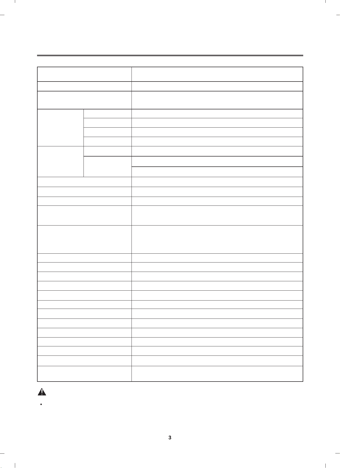
1. SPECIFICATION
ITEM
POWER SUPPLY
PRODUCT WEIGHT
WASHING
ELECTRICITY
CONSUMPTION
REVOLUTION
SPEED
OPERATION WATER PRESSURE
CONTROL TYPE
WASH CAPACITY
SPIN
DRAIN MOTOR
WASH HEATER
WASH
SPIN
DIMENSION
Refer to 1 page
220 V - 240 V ~, 50 Hz
62kg
155 W
490 W
37 W
2000 W
46 rpm
F4J6TYP0W : No Spin / 400 / 800 / 1000 / 1200 / 1400
F2J6TYP0W : No Spin / 400 / 800 / 1000 / 1100 / 1200
100 ~ 1000 kPa (1.0 kgf / cm2~ 10.0 kgf / cm2)
Electronic
Refer to the Rating Label
600mm x 560mm x 850mm
WASH PROGRAM
RINSE
DOOR SWITCH TYPE
WATER LEVEL
RESERVATION
SENSING LAUNDRY AMOUNT
FUZZY LOGIC
DISPLAY REMAINING TIME
ERROR DIAGNOSIS
POWER AUTO OFF
CHILD LOCK
AUTO RESTART
TIME SAVE
SMART
Cotton, Cotton +, Mix, Easy Care, Duvet, Sports Wear,
Dark Wash, Silent Wash, Gentle Care / Stain Care / Quick 30 /
Download Cycle
Normal, Rinse+, Rinse Hold
PTC+Solenoid
by Pressure Sensor S/W
From 3 hours to 19 hours
Adapted
Adapted
Adapted
13 items
Adapted
Adapted
Adapted
Adapted
NFC (Tag On function)
Smart Diagnosis function (3.0)
WARNING
To reduce the risk of personal injury, adhere to all industry recommended safety procedures including
the use of long sleeved gloves and safety gla
Failure to follow all of the safety warnings in this manual could result in property damage, personal
injury or death.
ss es.
Page 4
2.FEATURES & TECHNICAL EXPLANATION
4
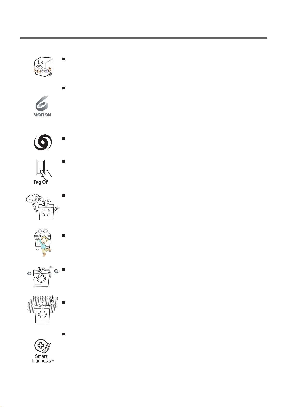
2-1. Product Features
Inverter Direct Drive system
The advanced Brushless DC motor directly drives the drum without
belt and pulley.
6 Motion
Washer is able to perform various drum actions or a combination of
different actions depending on the wash program selected.
Combined with a controlled spin speed and the ability of the drum to
rotate both left and right, the wash performance of the machine is greatly
improved, giving you perfect results every time.
Turbo Wash
Wash the laundries in 1 hour with energy and water saving.
Tag on
This is a function that may use Diagnosis, Download Course, Washing
Coach, One Touch Washing, etc. when you touch the Tag On logo of
the washing machine by using your smartphone with NFC.
More economical with Intelligent Wash system
Intelligent Wash System detects the size of load and water temperature,
and then determines the optimum water level and washing time to
minimize energy and water consumption.
Child Lock
The Child Lock prevents children from pressing any button to change
the settings during operation.
Low noise speed control system
By sensing the amount of load and balance, it evenly distributes load
to minimize the spinning noise level.
Auto Restart
Auto Restart allows the program to restart all by itself in case of power
failure. It does from the stage where it stopped.
SmartDiagnosis™
Should you experience any technical difficulty with your washing
machine, it has the capability of transmitting data by phone to the
Customer Information Center. The call center agent records the data
transmitted from your machine and uses it to analyze the issue,
providing a fast and effective diagnosis.
Page 5
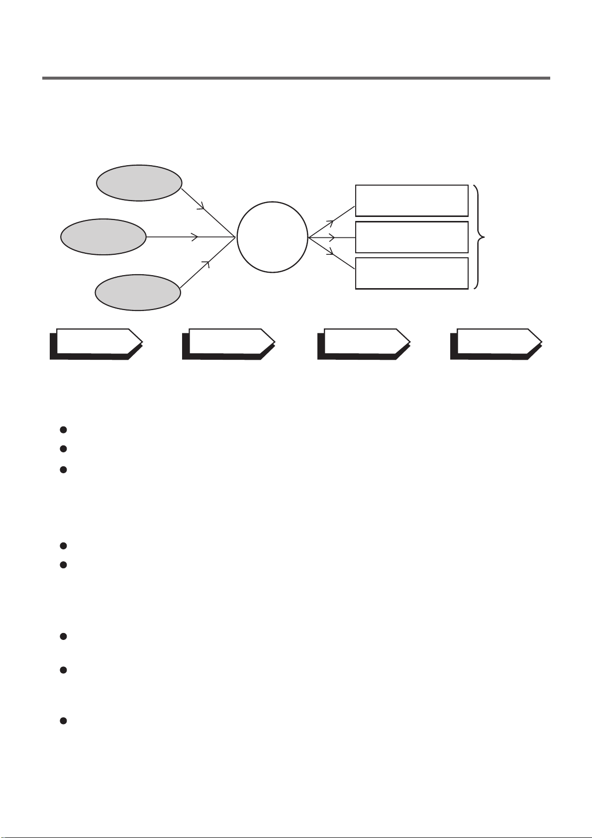
2-2. DETERMINE WASHING TIME BY FUZZY LOGIC
5
To get the best washing performance optimal time is determined by sensing the water
temperature, selected washing temperature and laundry amount.
water
temperature
washing time
selected
washing
temperature
SENSING
laundry
amount
PROCESSING
FUZZY
LOGIC
rinse time
spin rhythm, time
DETERMINATION
the best
washing
performance
EFFECT
2-3. WATER LEVEL CONTROL
This model adopts a pressure sensor which can sense the water level in the tub.
Water supply is stopped when the water level reach the preset level, then washing program proceeds.
Spinning does not proceed until the water in the tub reduces to a certain level.
2-4. THE DOOR CAN NOT BE OPENED
While program is operating.
While Door Lock light is on.
2-5. NFC (Tag On Function)
The Tag On function can only be used with smart phones equipped
with the NFC function and based on the Android operating system (OS).
Position your smart phone so that the NFC antenna on the back of
your smart phone matches the position of the Tag On icon on the
appliance.
NFC reading performance of your smart phone is must be higher than
a certain level for using this function.
Page 6
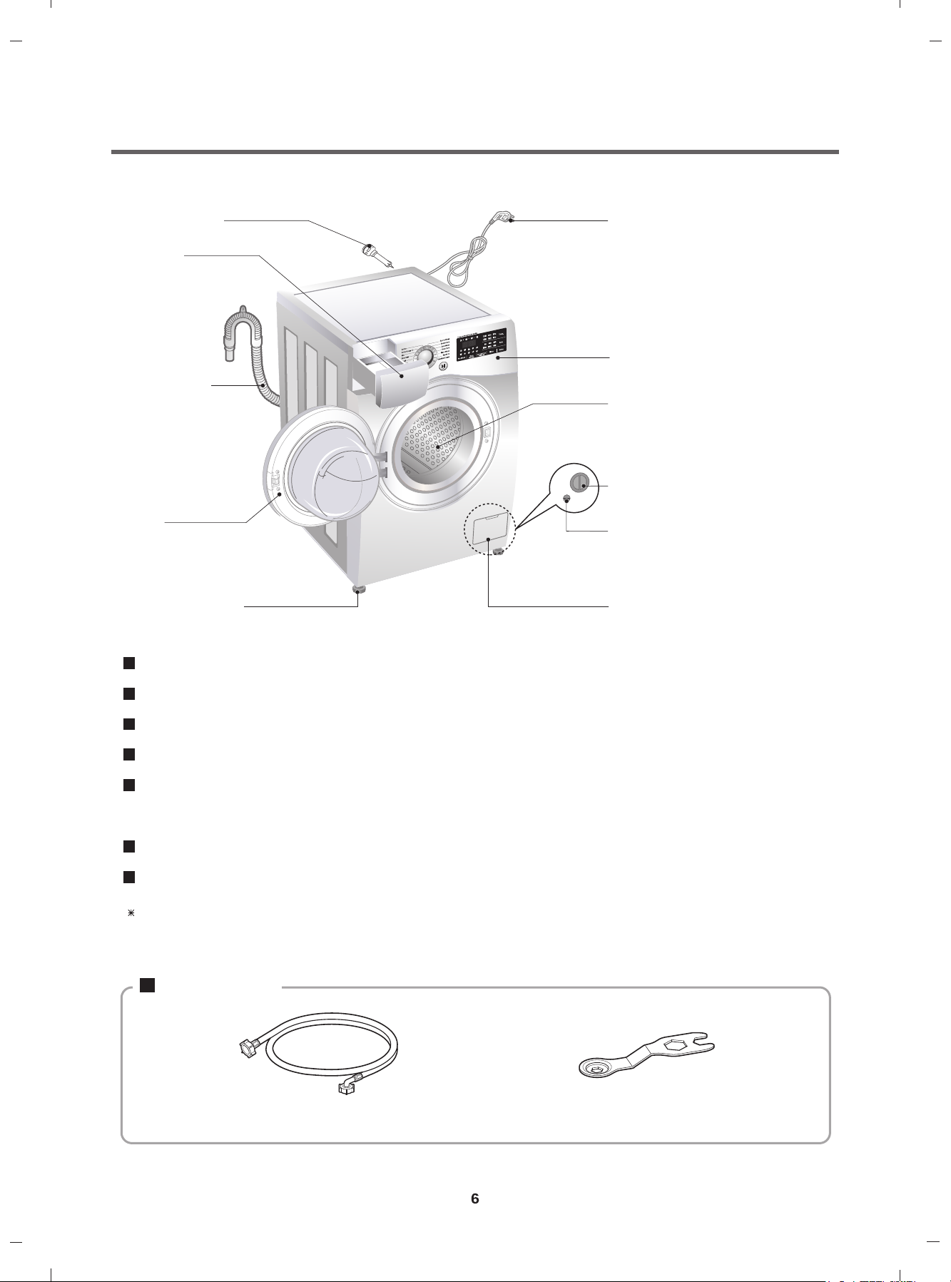
3. PARTS IDENTIFICATION
Transit bolts
Drawer
(For detergent and
fabric s oftener)
Drain hose
Door
Adjustable feet
Power plug
If the supply cordis damaged,
it mustbe replaced by the
manufactureror its service agents
or a similarly qualified person in
order to avoid a hazard.
Control panel
Drum
Drain pump filter
Drain plug
Lower cover cap
Name : Front loading washing machine
Power supply : 220 - 240 V~, 50 Hz
Size : 600 mm (W) X 560 mm (D) X 850 mm (H)
Weight : 62 kg
Max.Watt : 2100 W
0.45 W (The off-mode, The left-on mode)
Wash capacity : 8 kg
2
Permissible water pressure : 100 - 1000 kPa (1.0 - 10.0 kgf / cm
)
The appearance and specifications may vary without notice to improve the quality of the unit.
Accessories
Inlet hose Spanner
Page 7
4.INSTALLATION
7
INSTALLATION
The appliance should be installed as follows.
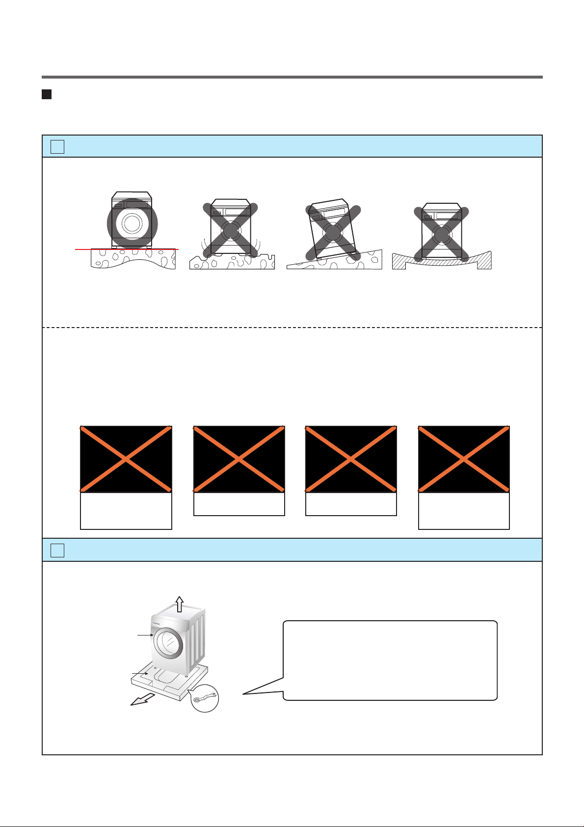
1
Check the conditions of installation area.
1. Check level ground.
horizontal
On raised foundations or upper level homes, the vibrations can be caused by the type of flooring.
It may be necessary to move the machine to a different area in the home or have the floor
reinforced to properly support the operation of the unit.
2. Check for humidity or any foreign objects under the feet.
Clean the floor, there should be no foreign objects under the feet.
If the unit has foreign objects underneath the feet, this will prevent the unit from being leveled properly
and will cause vibrations and slipping.
Remove any foreign objects, if any from underneath the machine and level unit properly.
See below for examples of foreign objects.
Purchased
stopper
2
Open the box and check appliance condition.
Washer
Carpet Paper Laminated
paper
This leveling (or spanner) wrench must
be used to remove the shipping bolts
Base Packing
Spanner
and level the unit. This should be kept
for future use.
Page 8
1. 2. 3.
1. 2. 3.
8
Page 9
6
9
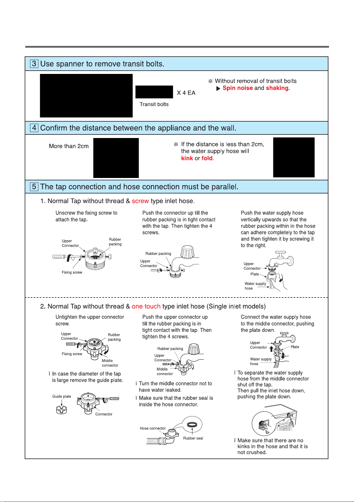
Connect Drain Hose.
If the drain hose is not installed properly, the unit will not drain properly.
This allows water to back flow into the unit which can cause odors.
Refer to Owner Manual for proper drain hose installation.
The odor could also be coming from the home’s drain to which the drain hose is attached.
Laundry tub
about 100 cm
about 145 cm
about 105 cm
max. 100 cm
min. 60 cm
Max. 100cm
min. 60cm
Hose
Retainer
Tie
strap
Max. 100cm
min. 60cm
In this type of drain hose installation, the odor could be coming from the standpipe.
This odor can come up the drain hose and into the unit.
Pour a cup or two of bleach or vinegar down the home drain
and let it sit for 24 hours before running another cycle.
This will help eliminate odor from the home drain.
If a cycle is started too soon after doing this, it will not help the issue.
7
Connect power plug.
Connect the power plug to the wall outlet. Avoid connecting several electric devices,
it may be the cause of a fire.
Page 10
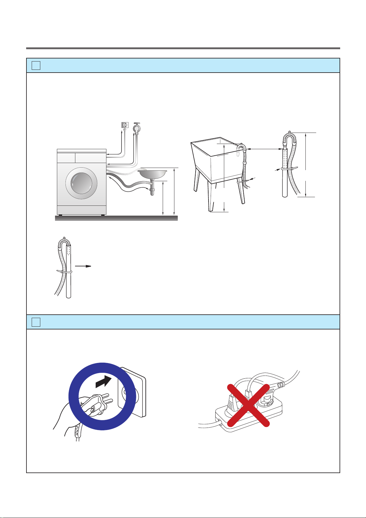
8
Floor
No Gap
10
Check the horizontality with a level (Gage).
Step 1
If washing machine legs are loose or not Screwed in, then tighten with the spanner wrench.
Using the level, level the washing machine from front to back and side to side.
A level
Higher
Tighten
Adjustable feet
Step 2
Use the spanner wrench to adjust Legs until level and try the Diagonal test.
Diagonal test
How to perform a diagonal test:
Place your right hand on the back, right corner and your left hand on the front,
left corner of the unit, then attempt to rock the unit from corner to corner.
Then, move your right hand to the front, right side and your left hand to the
back, left corner and attempt to rock the unit from corner to corner.
If the unit is level, it will not rock. However, if the unit is not level, it will rock.
If the unit rocks, it will be necessary to adjust the leveling feet of the unit.
Adjust the foot under the hand that is on the front of the machine.
Lock nut
Adjustable bolt
Gap
Floor
No Gap
Floor
Tighten
Higher
Adjustable feet
Lower
Tighten
Adjustable feet
Lower the foot until there is no gap between floor and foot.
And only use adjustment rubber when difference at the leg adjustment is more than 10mm.
Rubber Cup
Rubber Cup
4620ER4002A
(Black)
for Tile floors
4620ER4002B
(Gray)
for Wooden floors
10mm
Step 3
Perform a Rinse and Spin with some clothing in the machine.
To do this, put 2~3kg of clothing in the unit, turn on the unit, Select the Rinse+Spin
and then start. When the unit reaches the spin cycle, watch for vibrations.
If the unit is vibrating, make small adjustments to the leg until they subside. (Repeat step 2)
Step 4
Tighten the lock nut against the base of the machine to lock the position leg.
Tighen the lock nut
Page 11
9
11
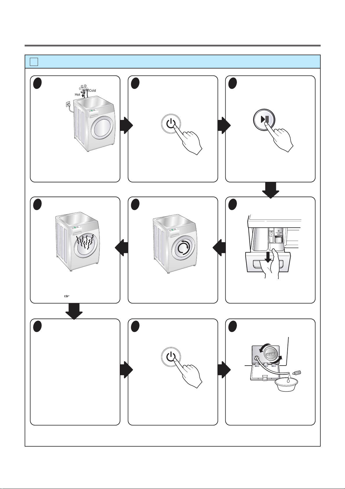
Test operation
Preparation
1
for
washing.
· Connect the power plug to the
outlet.
· Connect the inlet hose.
Check the water heating.
6
Press the power button.
2
Check automatic reverse turn.
5
Press the START/PAUSE
3
button.
· In case of Coloreds program.
Check the water supply.
4
· Touch the Temp and Medic
Rinse button simultaneously and
the present temperature will be
displayed.
Check the drain and spin
7
functions.
· Turn power off and then power on.
· Select the spin rpm
· Press the START PAUSE button.
· Check the spin and drain
functions.
Page 20
· Check if the drum rotates
clockwise and counterclockwise.
Turn power off and open
8
the door.
· Turn power off and then power on.
· Listen for a click to determine if the
door is unlocking.
· Check if water is supplied through
the detergent dispenser.
Water removal.
9
· If SVC is needed during check,
remove the remaining water by
pulling out the hose cap.
Page 12
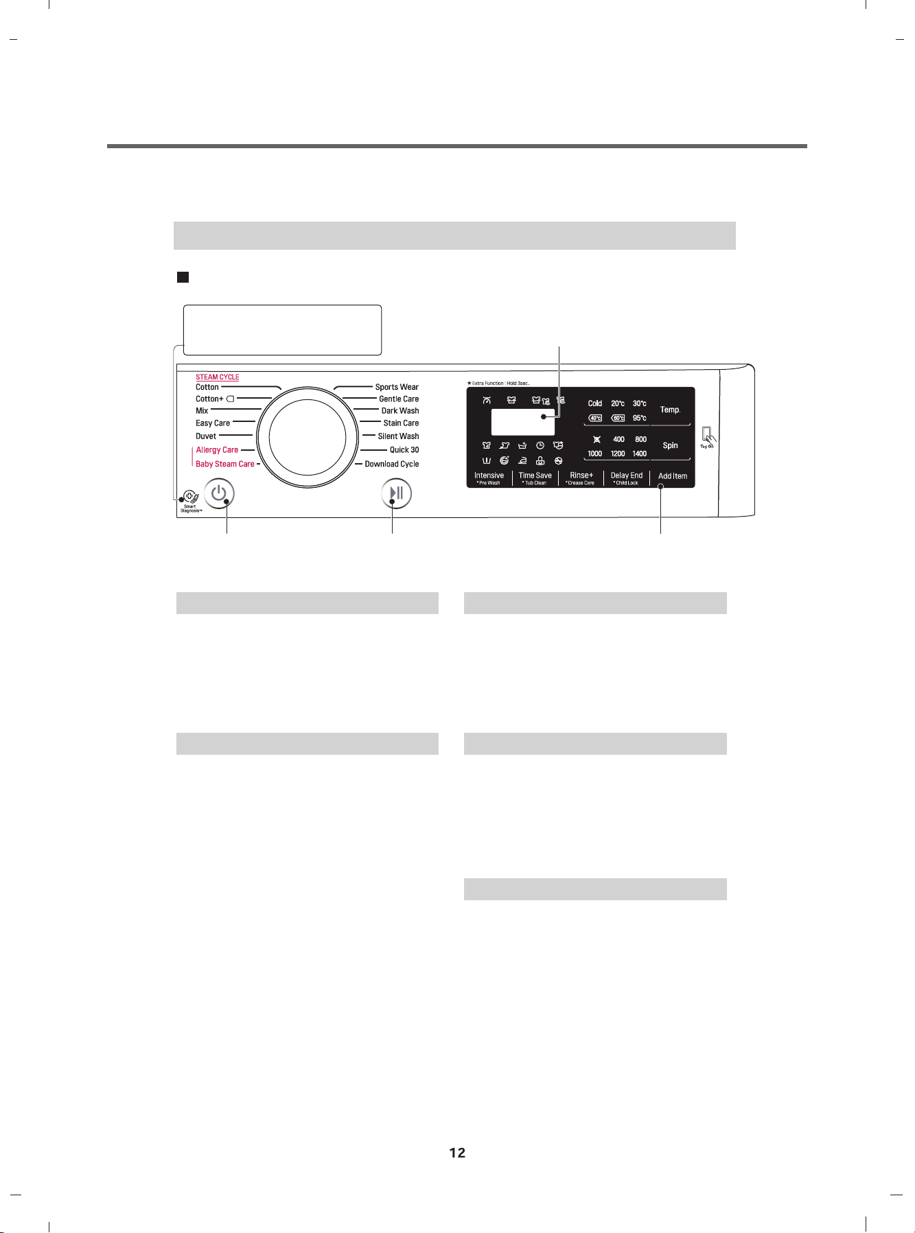
5. OPERATION
How to use washer
Control panel
SmartDiagnosis™ function is
available only for the products with
a SmartDiagnosis™ mark.
LED display
Power Button
Program dial
Start/Pause
Button
Power
Press the Power button to turn power on
and off.
To cancel the Time Delay function, the
power button should pressed.
Start/Pause
This Start/Pause button is used to start
wash cycle or pause the wash cycle.
If temporary stop of wash cycle is
needed, touch the Start/Pause button.
When in Pause, the power is turned off
automatically after 4 minutes.
Options
Program Dial
Programs are available according to the
laundry type.
Lamp will light up to indicate selected
program.
LED display
The display shows the settings, estimated
time remaining, options, and status
messages for your washer.
The display will remain on through the
cycle.
Options
This allows you to select an additional
cycle and will light when selected.
Use thise buttons to select the desired
cycle options for the selected cycle.
Page 13
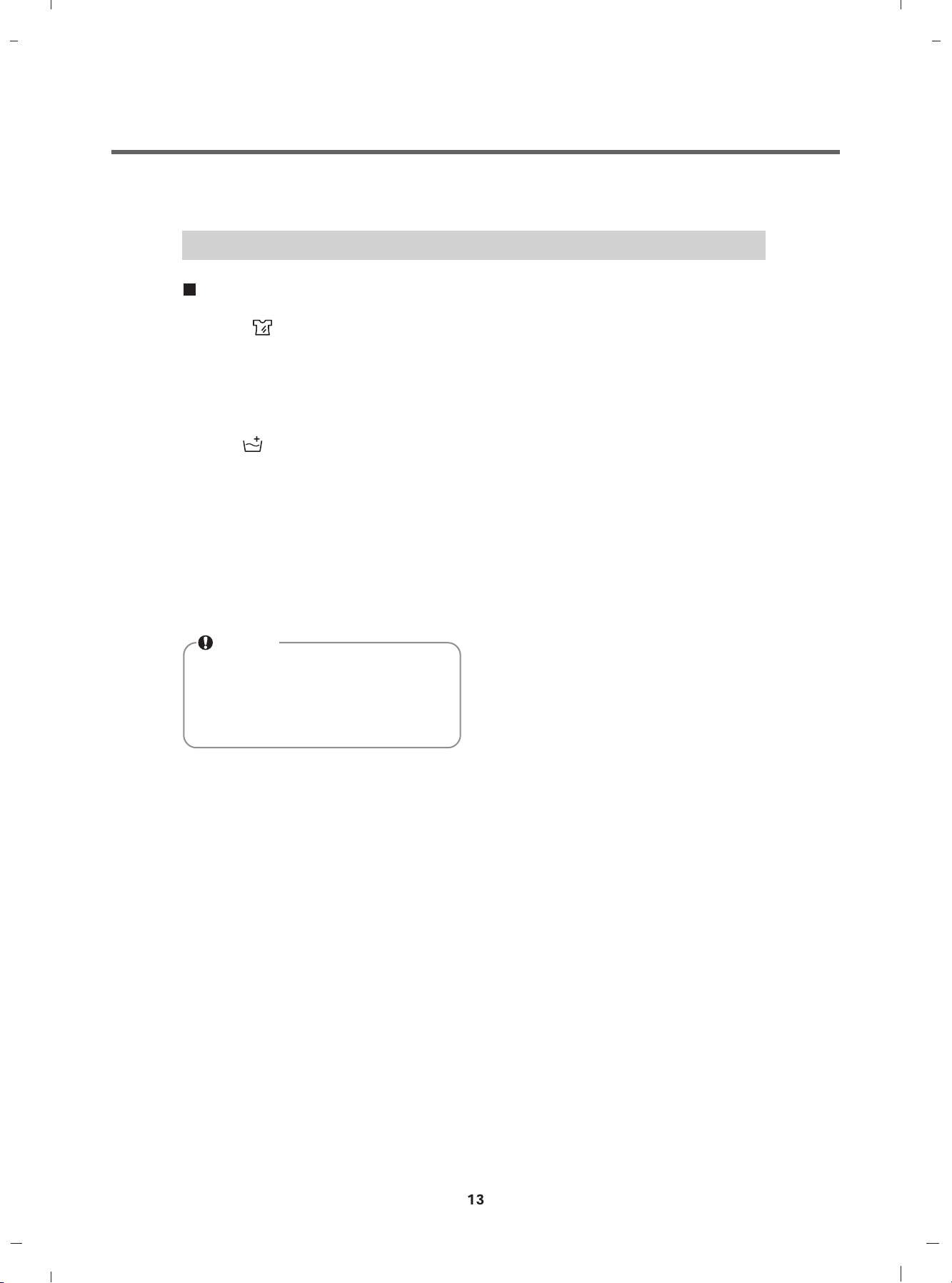
How to use washer
Options
Intensive ( ) : If the laundry is normal
and heavily soiled, “Intensive” option is
effective.
Rinse + ( ) : Add rinse once.
Dealy End :
You can set a time delay so that the washing
machine will start automatically and nish
after a specied time interval.
NOTE
The delay time is the time to the end
of the programme, not the start.
The actual running time may vary
due to water temperature, wash load
and other factors.
1. Touch the Power button.
2. Select a cycle.
3. Touch the Time Delay button and set time
required.
4. Touch the Start/Pause button.
Page 14
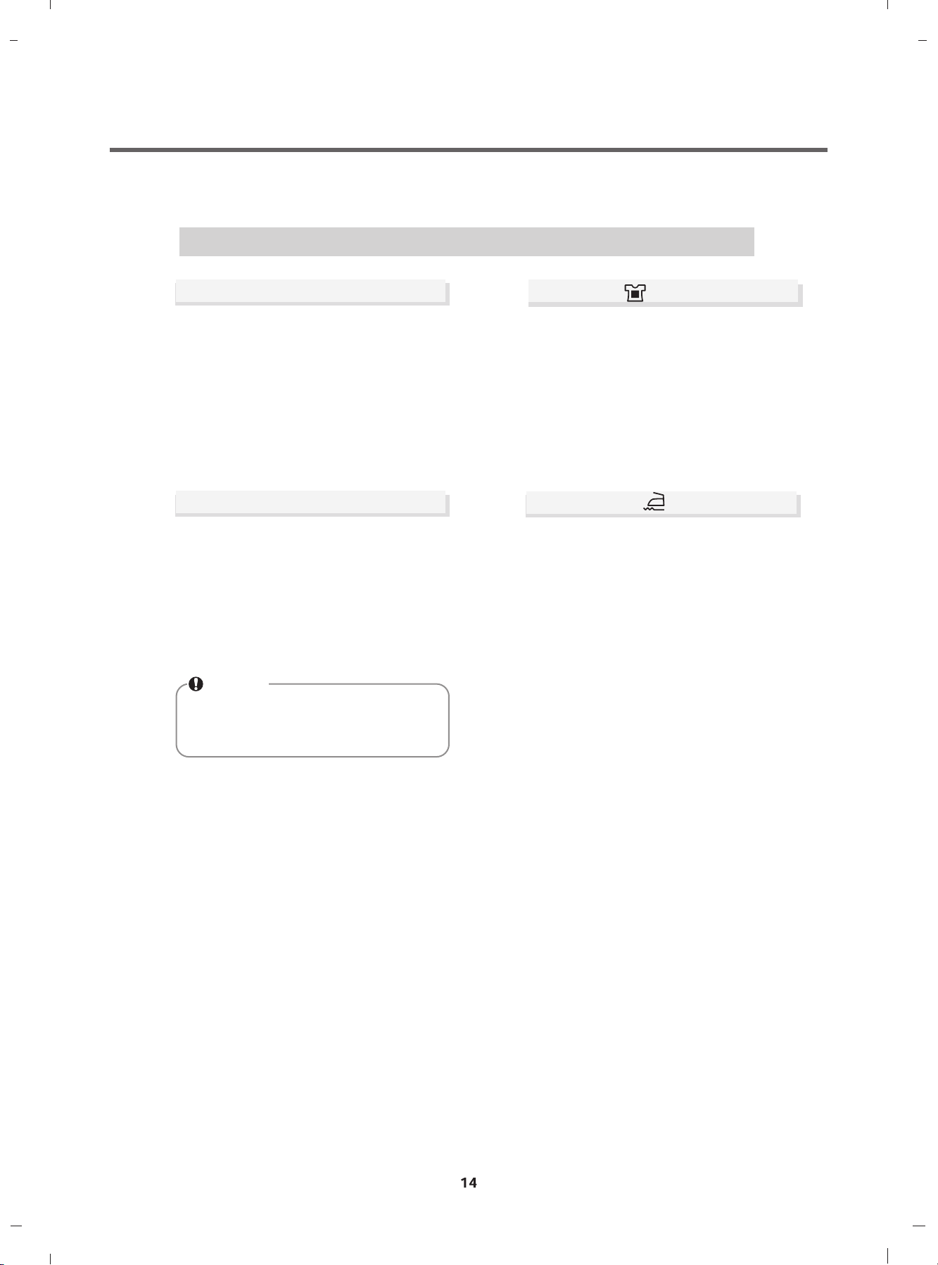
How to use washer
Temp.
By touching the Temp. button the water
temperature can be selected.
- Cold
- 20°C, 30°C, 40°C, 60°C, 95°C
Water temperature can be selected
according to the program.
Spin
Spin Speed level can be selected by
touching 'Spin' button repeatedly.
Spin Only
1. Touch the Power button.
2. Touch the Spin button to select RPM.
3. Touch the Start/Pause.
NOTE
When you select "No Spin", it will still
rotate for a short time with low speed to
drain quickly.
Pre Wash ( )
If the laundry is heavily soiled, “Pre Wash”
course is effective.
1. Touch the Power button.
2. Select a cycle.
3. Touch the Pre Wash button.
4. Touch the Start/Pause button.
Crease Care ( )
If you want to prevent creasing, select
Crease Care option.
1. Press the Power button.
2. Select a cycle.
3. Touch the Crease Care button.
4. Press the Start/Pause button.
Page 15
How to use washer
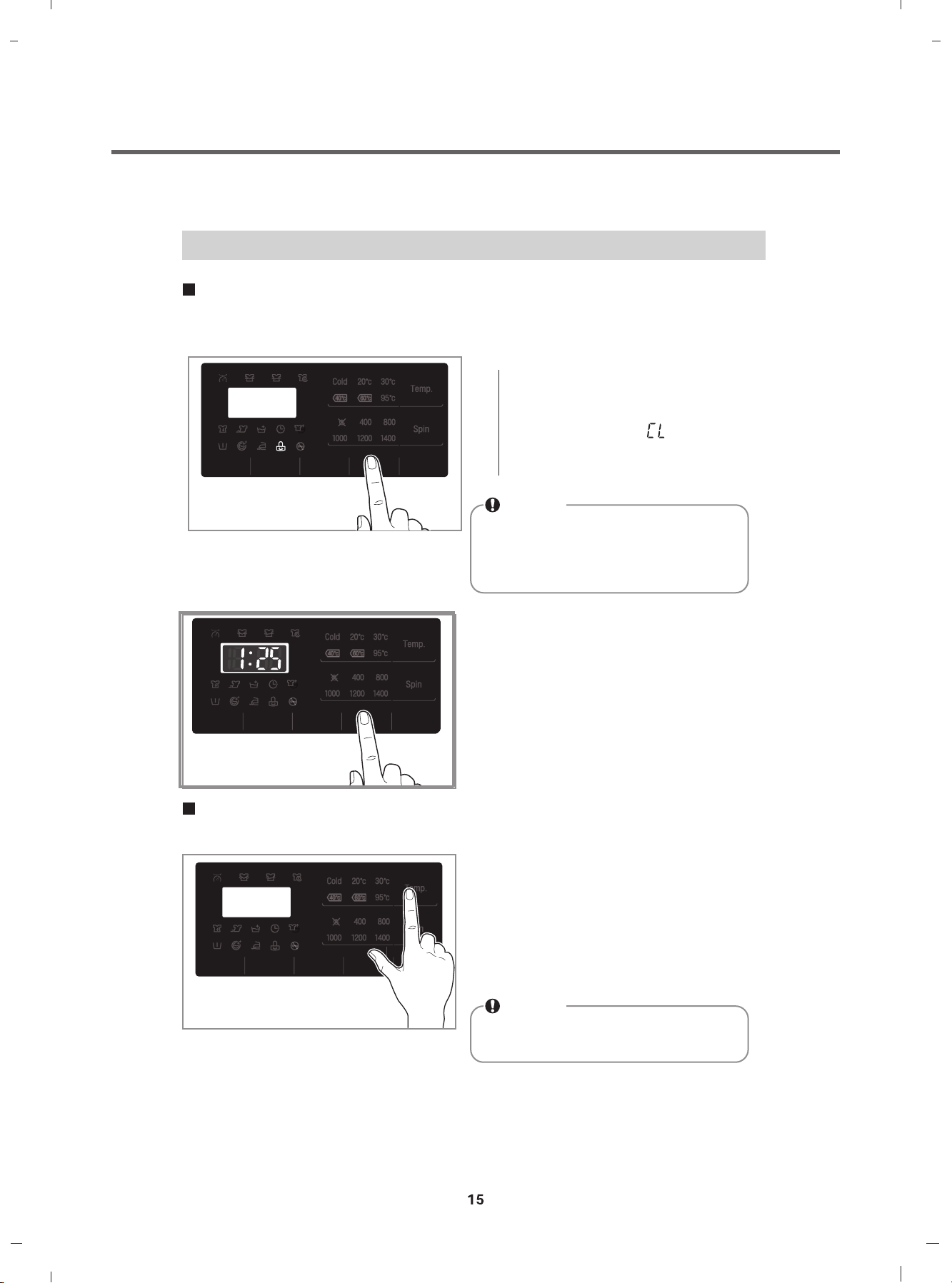
Child Lock
Select this function to lock the buttons on the control assembly to prevent tampering.
"Child Lock" can be set only during the washing cycle.
Locking the control panel
1. Touch and hold the Child Lock button for
3 seconds.
2. A beeper will sound, and ' ' will appear on
the LED display.
When the child lock is set, all buttons are
locked except the Power button.
NOTE
Turning off the power will not reset the
child lock function. You must deactivate
child lock before you can access any
other functions.
Unlocking the control panel
1. Touch and hold the Child Lock button for
3 seconds.
2. A beeper will sound and the remaining time
for the current programme will reappear on
the LED display.
Beep On / Off
The Beep on/off function can be set only during the washing cycle.
1. Touch the Power button.
2. Touch the Start/Pause button.
3. Touch and hold the Temp. and Rinse button
simultaneously for three seconds to set Beep
on/off function.
Once the Beep on/off function is set, the setting
is memorized even after the power is turned off.
NOTE
If you want to turn the Beeper off,
simply repeat this process.
Page 16
How to use washer
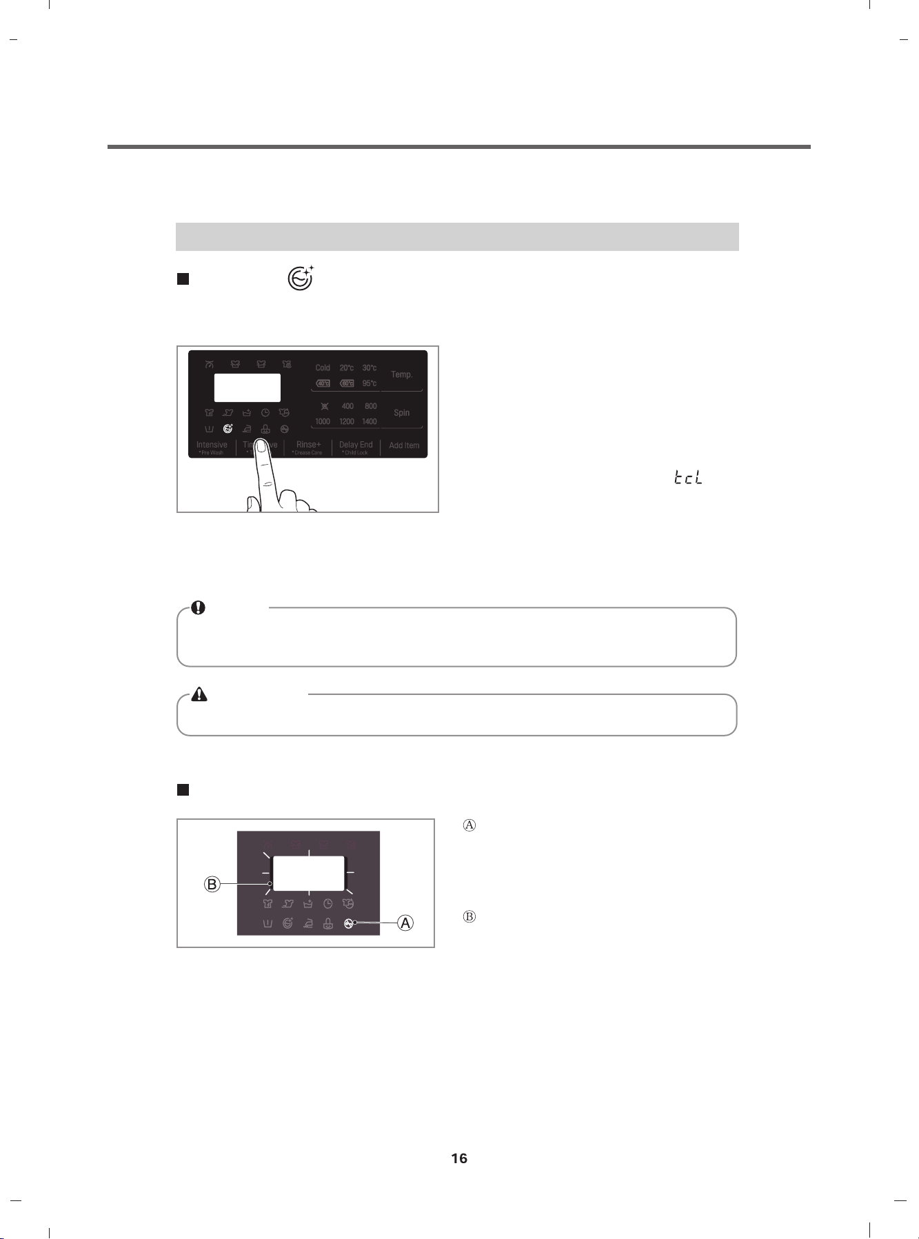
Tub Clean ( )
Tub Clean is a special cycle to clean the inside of the washing machine.
A higher water level is used in this cycle at higher spin speed. Perform this cycle regularly.
1. Remove any clothing or items from the
washer and close the door.
2. Open the dispenser drawer and add Anti
limescale(e.g. Calgon) to the main wash
compartment.
3. Close the dispenser drawer slowly.
Power On and then touch and hold Tub
4.
' '
Clean button for 3 seconds. Then
tub clean pictogram will be displayed on the
LED display.
5. Touch the Start/Pause button to start.
6. After the cycle is complete, leave the door
open to allow the washer door opening,
flexible gasket and door glass to dry.
NOTE
Do not add any detergent to the detergent compartments.
Excessive suds may generate and leak from the washer.
and
CAUTION
If there is a child, be careful not to leave the door open fo r too long.
Door Lock & Detecting
“Door Lock” - For safety reasons, the
door will lock while machine is in use and the
“Door Lock” icon will light up. You can safely
open the door after the “Door Lock” icon
turns off.
While "Detecting" is shown on the
display the washing machine rotates slowly
and detects how much laundry is loaded in
the drum.
It will take a short time.
Page 17
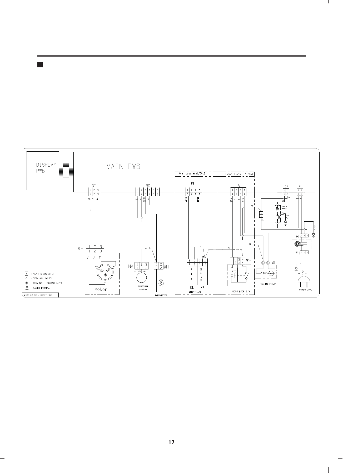
6.
WIRING DIAGRAM / PCB LAYOUT
Wiring Diagram
Page 18
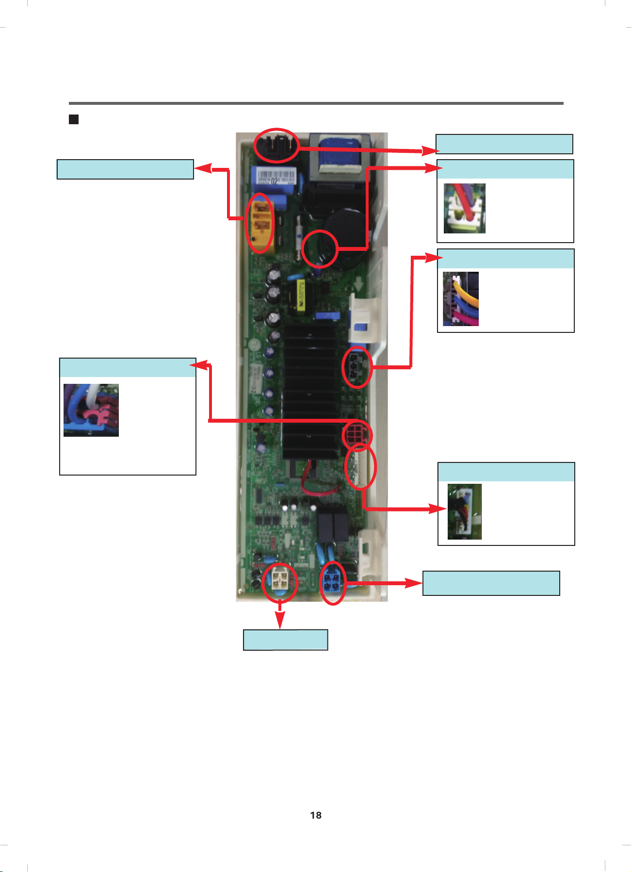
PCB Layout (Main)
Washer Heater
PCB POWER
Water sensor
White:Common
violet-blue:
R≈22Ω
AG heater
White:Common
Violet:Short
Orange:Long
Moter Stator Control
V-U/U-W
/W-V
→R:8~11Ω
Inlet valve
display
Door Switch/
Main Motor Control
Page 19

7. TROUBLESHOOTING
7-1. CHECK BEFORE SERVICE
1
Before servicing ask the customer what the trouble is.
2
Check the adjustments. (Power supply :220-240V~, Removal of transit bolts etc..)
Check the troubles referring to the troubleshooting.
3
Decide service steps referring to disassembly instructions.
4
Then, service and repair.
5
After servicing, operate the appliance to see whether it works OK or NOT.
6
7-2. LOAD TEST MODE
1
Turn on, and touch ‘Wash’ and ‘Rinse’
at the same time in 1 second.
2
The washer must be empty and the controls must be in the off state.
Press Power with above two buttons pressed and then buzzer will sound.
3
Press the Start/Pause button repeatedly to cycle through the test modes
4
0
1
2
3
4
5
6
7
8
9
10
11
Turns on all light and locks the door.
Tumble clockwise
Low speed spin
High speed spin
Inlet valve for prewash turns on.
Inlet valve for main wash turns on.
Inlet valve for hot water turns on.
Inlet valve for atomizing turn on.
Tumble counterclockwise
Heater turns on for 3 sec.
Drain pump turns on.
Off
Display StatusNumbers Check Point Remark
PGM Version Information
rpm(42~50)
rpm (60)
rpm (130~140)
Water level frequency
Water level frequency
Water level frequency
Water level frequency
rpm
Water temperature
Water level frequency
-
For Hot&Cold Model
Page 20

7-3. HOW TO CHECK THE WATER LEVEL FREQUENCY
Touch the Spin and RINSE+ button simultaneously.
Keeping touch, the digits indicate the water level frequency.
Page 21

7-4. ERROR DISPLAY
21
If you press the Start/Pause button in error condition, any error except will disappear and the
machine will change into the pause status.
In case of
error is not resolved within 4 min., the power will turn off automatically and the error only will blink.
But in the case of
, , if the error is not resolved within 20 sec., and in case of all other errors, if the
, the power will not turn off.
ERROR SYMPTOM CAUSE
1
2
3
4
5
6
WATER INLET
ERROR
WATER OUTLET
ERROR
OVERFLOW
ERROR
PRESSURE SENSOR
S/W ERROR
DOOR OPEN
ERROR
UNBALANCE
ERROR
• Not reached the water level(248) within 10 minutes
after water supplied or not reached to the preset
water level within 25 minutes.
• Not fully drained within 10 minutes.
• Water is overflowing (under 21.3kHz).
If " " is displayed, the drain pump operates
to drain the water automatically. Page 28
• The pressure sensor switch is out of order.
• In case of operating the reservation function or the
other function with door opened. Close the door,
then the error display is resolved.
• The door switch is out of order.
• The appliance is tilted.
• Laundry is gatherd to one side.
Page 24
Page 26
Page 29
Page 31
Page 25
THERMISTOR(HEATING)
7
ERROR
• The THERMISTOR is out of order. Page 33
Page 22

ERROR SYMPTOM CAUSE
8
9
10
MOTOR LOCKED
ERROR
POWER
FAILURE
NFC MODULE
ERROR
The connector in the LEAD WIRE ASSEMBLY is
not connected to the connector of STATOR
ASSEMBLY.
Reconnect or repair the connector.
Page 36
The washer experienced a power failure
Press the start/pause button
The connector in the DISPLAY PCB ASSEMBLY
is not connected to the connector of
NFC PCB ASSEMBLY.
Reconnect or repair the connector.
The NFC HARNESS between the NFC PCB
ASSEMBLY and DISPLAY PCB ASSEMBLY is cut
(open circuited).
Replace the DISPLAY PCB ASSEMBLY.
The NFC PCB ASSEMBLY is out of order/defective.
Replace the NFC PCB ASSEMBLY.
11
NFC VERSION
ERROR
* nC is displayed only in the first screen of the Load
Test Mode.
NFC version is not matched.
Replace the NFC PCB ASSEMBLY.
* nU is displayed only in the first screen of the Load
Test Mode.
Page 23

7-5. TROUBLESHOOTING WITH ERROR
Symptom Check Point
1. INLET VALVE
ERROR
Pre wash
1.Check Electric Wiring.
.ecnatsiseR s’evlav telnI kcehC.2
3.Check Inlet valve clogged.
4. Voltage of the inlet valve’s connector.
-. Va lve running : 120Vac ±5%
Main wash
Page 24

Water Inlet Error (IE)
[Note] Environmental safety check list
1. No water tap leakage or freeze 4. No entanglement of water supply hose.
2. No water shortage. 5. No water supply hose leakage
3. The inlet filter is not cloggeed.
Is the water tap closed ?
YES
NO
When there is water in the tub,
is the water level frequency
over 26.0khz ?
YES
NO
Is the Connector connected correctly to the Main PCB
and the Inlet Valve ? is the Harness alright ?
YES
Check the Water tap and open it fully.
Check the Air Chamber and the Tube (clogged)
Check the water level frequency again,
if it is over 26.2KHz, replace the Pressure switch.
NO
Reconnect or repair the Connector .
Or replace the Harness .
Is the resistance of each lnlet valve within 3.5 ~4.5 k ?
1
2
Pre Valve
1
Main Valve
2
YES
When the washing machine is started, is the inlet valve
operating?
NO
NO
Replace the Inlet Valve .
Replace the Main PCB .
Page 25

Unbalanced Error (UE)
25
Does the load lean toward one
side, or is the load a few items?
NO
Is the laundry mixed?
NO
YES
YES
The few items of clothing will clump together
and their weight will be in one place on the drum,
throwing the weight off during spin mode.
So add some laundry to overcome UE error.
And rearrange load to allow proper spinning.
Try rearranging the laundry in drum
Or the laundry is separated by size, type, and color.
Separate by size,
type and color
Is the washing machine installed
at an angle?
YES
Adjust the height of washing
machine to be kept horizontally.
( Page 7)
Page 26

Water Outlet Error (OE)
26
Is the drain hose kinked ?
YES
NO
Is the Pump filter clogged ?
YES
NO
Next Page
* How to disassemble and clean pump filter
Open the Cover by coin or
finger(only new model)
Drain water by removing the
hose cap.
Check drain hose for kink and straighten the Hose.
Drain Hose
Check & Clean Pump Filter.
This kind of accumulation on the drain filter not only
prevents proper drainage, but also will promote
bacteria growth and cause odors.
This drain filter should be cleaned once a month.
Disassemble the pump
filter by turning the filter
cap counterclockwise.
Pump Filter
Cover
Filter Cap
Filter clogged by foreign objectsAssemble & close cap
filter CapHose Cap
Clean the filter
Page 27

Is the Standpipe Height greater
27
than 1.0 m above the floor?
NO
YES
Observe Standpipe Height requirements
of 1.0m maximum.
- Your washer will not be able to drain out
water adequately, if the standpipe exceeds 1.0 m.
In this case, water may flow back into the washer.
When there is no water in the
pump casing, is the water level
frequency over 26.0khz ?
YES
Is the Connector connected correctly to
the Main PCB and the Pump Motor ?
Or is the Harness alright ?
YES
Is the resistance of the Pump Motor out
of range 152~175Ω?
Or is the Impeller operating normally?
Escape Binding
NO
NO
Check the Air Chamber and the Tube (clogged).
Check the water level frequency again, if it is over
25.5KHz, replace the If it is clogged, Pressure
switch.
Reconnect or repair the Connector.
Or replace the Harness.
YES
Replace the Pump Motor.
OR
NO
Does the Pump motor start, when the spin mode
starts?
YES
If the drain hose blocked?
NO
YES
Replace the Main PCB.
Clean the drain hose.
Page 28

FE (Overflow Error)
Power off for 10sec. Then power on.
Is the water level over reference line and is the water level frequency under 21.3kHz?
* Water level frequency
- Touch and Hold ‘ Spin’ & ‘ Rinse + ’
simultaneously.
NO
Is water continuously
coming into the drawer?
YES
Replace the Main PCB.
Replace the Inlet Valve assembly.
NO
YES
Drain out the water and then
check the Air Chamber and the Tube (clogged).
If FE is displayed again,
then replace the Pressure Switch .
If FE is displayed again,
then replace the Main PCB .
Page 29

Pressure Sensor S/W Error (PE)
29
Is the Connector connected correctly to
the Main PCB and the Pressure Switch ?
Is the Harness alright ?
YES
Is the resistance of the Pressure Switch
out of range?
[Pin1 ~ Pin3]
21~23Ω )
NO
YES
Reconnect or repair the Connector.
Or replace the Harness.
Replace the Pressure Switch.
NO
Is the air chamber and the tube clogged?
NO
Replace the Main PCB.
YES
Check air chamber and remove foreign material.
Page 30

Symptom Check Point
30
1. PRESSURE
SENSOR ERROR (PE)
Pressure Sensor
MAIN PWB
1.Check Electric Wiring.
2.Check Pressure sensor‘s Resistance.
3.Check Air chamber and Tube clogged.
(3)
(2)
(1)
BL1
5V
BL6
Micom
Pressure
Sensor
(1) ~ (3)
Main
PWB
BL6 4
BL6 5
th
1 1
2 2
3 3
4 4
5 5
6 6
VT WH SB
11223
NA
3
Resistance
[Ω]
~
th
21 ~ 23
10%)
(±
PRESSURE
SENSOR
Page 31

Door Open Error (dE2)
31
Is the door closed?
YES
Is the Door assembly in line with door switch ?
Scratch by Latch Hook
or
Touching
YES
NO
Does the Spring of Latch Hook actuate?
YES
NO
NO
Close the door fully.
Lift up & Close the door.
If the dE is displayed, Replace the Door Bracket.
Replace the Spring
Does the Door Switch operate as follows?
* Door Locking time : 1~8 sec.
1
Check the time between from
input the power to parts
move up, then Door locked.
*
Door Releasing time : 25~100 sec.
Check the time between from off the
power to parts
move down, then Door released.
1
1
Door Switch Error (dE1)
Is the Connector connected correctly to
the Main PCB and the Door Switch?
Is the Harness alright ?
YES
NO
NO
Replace the Door switch.
Reconnect or repair the Connector.
Or replace the Harness.
Is there clicking sound once or twice when the
START/PAUSE button is pressed to start the
cycle? No Replace the MAIN PWB ASSEMBLY.
Page 32

Symptom Check Point
32
1. DOOR OPEN
ERROR (dE)
1.Check Electric Wiring.
2.Check latch hook spring. (Cracked)
3.Check Door switch‘s Resistance.
4.Check Voltage of Door switch’s connector.
(5) (3)
(4) (2)
Door switch
(Type2)
(2) ~ (4) 700~1500Ω
(3) ~ (4)
Result Remarks
At 77�
90~120Ω
At 77�
With Latch
Infinity Without Latch
(4) ~ (5) Infinity
(2) ~ (4) 230Vac Voltage Input
(25� )
(25� )
Page 33

Thermistor (Heating) Error (tE)
Is the Connector connected correctly to
the Main PCB and the Thermistor and the Heater?
Is the Harness alright ?
Heater for Washing
NO
Is the resistance of the Thermistor out of range 44 ~
53 K at 25°C? (Page 17)
NO
YES
YES
Reconnect or repair the Connector .
Or replace the Harness .
Replace the Thermistor .
Is the resistance of the Heater out of range 24.5 ~
28.5 (for Washing) ? (Page 19)
NO
Replace the Main PCB .
[Note] Thermistor Spec
S
P
E
C
Temp
30 °C
40 °C
60 °C
70 °C
95 °C
105 °C
Resistance (k )
MIN
36.35 39.45 42.72
24.20 26.05 27.97
11.43 12.12 12.82
8.088 8.514 8.940
3.544 3.791 4.045
2.617 2.816 3.023
STD MAX
YES
Replace the Heater.
Page 34

Symptom Check Point
1. HEATING E rror (tE) 1.C heck Electric Wiring.
2.Check Heater’s Resistance.
3.Check Thermistor ‘s Resistance.
4.Water leaked into the Thermistor’s connector.
Wash Heater
YL BK
Heater
Wash Heater
(1) ~ (2)
Main
PWB
BK 3
YL 3
th
Resistance
[]
~
th
12 ~ 18
Page 35

Wash Thermistor
NA3
Thermistor
Wash
Thermistor
(1) ~ (2)
Main
PWB
NA3 4
NA3 5
th
~
th
Resistance
[k]
39.5 86(30)
26.1 104(40)
12.1 140(60)
8.5 158(70)
3.8 203(95)
2.8 221(105)
Remarks
(℃)
℉
35
Page 36

Motor Locked Error (LE)
[Pre Check]
Gentle wash cycles, such as Perm Press, Delicates, Hand Wash, and Wool/Silk should only be used for smaller loads.
Because these cycles are more gentle in tumbling and spinning, putting too much in the drum can register an issue
with the motor. Remove items, reset unit and test with a Rinse/Spin cycle.
Press the Power button & Start / Pause button.
Does the Drum stop when the start/pause button is pressed to start the cycle ?
Or Sometimes does the Drum rotateweakly (under 15rpm)?
YES
Is the Connector connected correctly to
the Main PCB and the Motor?
Is the Harness alright ?
YES
Disassemble the Rotor .
Is the Magnet of rotor cracked or broken?
NO
Is the resistance the same
betweenStator points?
V~U / U~W / W~V : 8~11
V U W
Magnet
V U W
NO
YES
NO
Reconnect or repair the Connector .
Or replace the Harness .
Replace the Rotor.
Replace the Stator.
Replace the Main PCB .
YES
Page 37

Symptom Check Point
1. NO POWER 1.Check Electric Wiring.
2.Check the Customer’s outlet.
3.Check Noise Filter.
4.Check LED on in Main PWB
retliF esioN
(3)
Noise Filter
WH1
(1)
(3)
(1)
Resistance
[Ω]
(2)
(1)
(3)
(3)
(1)
RD1
WH1 (1) ~ RD1 (3) 0
WH1 (3) ~ RD1 (1) 0
Page 38

8. TROUBLESHOOTING WITHOUT ERROR CODES
PF (Power Failure or no power)
Is the Power Plug connected
firmly to the power outlet?
And is the supply voltage
220~240V AC?
YES
Is Multi-plug socket used ?
NO
Is the Connector connected correctly to
the Main PCB and the Noise Filter ?
Is the Harness alright ?
NO
YES
NO
Reconnect Power Plug firmly.
Check the fuse or
reset the circuit breaker.
Don’t use Multi-plug socket.
Use Single Plug socket for
washing machine.
Reconnect or repair the Connector .
Or replace the Harness .
Noise Filter
PCB
YES
Is Red LED ON while power supplied ?
YES
Is the connectors connected
Correctly to the Display
PCB?
Main PCB
Noise Filter
NO
YES
Check and replace Main PCB .
Check connectors otherwise.
Replace Display PCB .
Page 39

Vibration & Noise During Spin
41
Have all the Transit Bolts been removed?
Washer
Packing Support
NO
Remove the Transit Bolts
YES
Refer to INSTALLATION. (Page 7)
Page 40

Detergent & Softener does not flow in
42
Is water supplied?
YES
YES
Is detergent & softener put in
the correct compartment of the drawer?
Main Wash
(Powder)
Pre Wash
(Powder)
YES
Only
softener
NO
NO
Reference (Amount of Detergent & Softener)
Detergent
Refer to [Water Inlet Error (IE)]
(page 23)
Put it in the Correct Position.
Softener
Is the Detergent caked or hardened?
YES
Clean the drawer and dispenser.
NO!!
OK!!
Check point
Page 41

Water Leak
43
1. Water Leak from Dispenser
Is the Dispenser Tray Damaged or warped?
NO
Is detergent & softener put in
the correct compartment of the drawer?
softener
Only
YES
NO
Reference (Amount of Detergent & Softener)
Replace the Dispenser Tray.
Put it in the Correct Position.
Main Wash
(Powder)
YES
Is the Detergent caked or hardened?
YES
Clean the drawer and dispenser.
Pre Wash
(Powder)
Detergent
Softener
NO!!
OK!!
Check point
Page 42

2. Water Leak from Dispenser
44
Are the gasket (seal)
and door cleaned regularly?
YES
Is the door or gasket damaged?
3. Unknown – Water on Floor
Are the inlet hoses loose or cracked/split?
Check!!
NO
YES
YES
Clean the periphery of Gasket and Door regularly.
Replace the damaged parts.
Replace the Inlet Hoses.
NO
Is the washer horizontal ?
YES
Are the drain filter and manual
drain hose open?
NO
NO
Adjust the height of washing machine to be kept
horizontally. (Page 7)
Turn the filter cap clockwise to close.
Page 43

Before using the Tag On function
45
• The Tag On function allows you to conveniently use the LG SmartDiagnosis™ and Cycle
Download features to communicate with your appliance right from your own smart phone.
• To use the Tag On function:
1. Download the LG Smart Laundry & DW App to your smart phone.
2. Turn on the NFC (Near Field Communication) function in your smart phone.
• The Tag On function can only be used with most smart phones equipped with the NFC
function and based on the Android operating system (OS).
Turning on the NFC function of the smart phone
1. Enter the "Settings" menu of the smart phone and
select "Share & Connect" under "WIRELESS &
NETWORKS".
2. Set "NFC" and "Direct Android Beam" to ON and
select "NFC".
3. Check "Use Read and Write/P2P receive".
NOTE
• Depending on the smart phone manufacturer and
Android OS version, the NFC activation process
may differ.
• Refer to the manual of your smart phone for
details.
Page 44

Before using the Tag On function
46
The Tag On guide
Tag On position
•
•
•
Because of the characteristics of NFC, if the transmission distance is too far, or if there is a
metal sticker or a thick case on the phone, transmission will not be good. In some cases,
NFC-equipped phones may be unable to transmit successfully.
Tag On:
Look for the Tag On icon next to the LCD screen on the
control panel.
This is where you position your smart phone when
using the Tag On function with the LG
SmartDiagnosis™ and Cycle Download features of the
LG Smart Laundry & DW App.
When you use the Tag On function, position your
smart phone so that the NFC antenna on the back of
your smart phone matches the position of the Tag On
icon on the appliance.
If you do not know the position of your NFC antenna,
move your smart phone very slightly in a circular
motion until the application verifies the connection.
•
Press in the LG Smart Laundry & DW app for a more detailed guide on how to use
the Tag On function.
•
NFC reading performance of your smart phone is must be higher than a certain level for
using this function.
Page 45

9. Par t i nspect i on
Page 46

48
Page 47

49
Page 48

Page 49

10. DISASSEMBLY INSTRUCTIONS
55
Remove the power cord from the outlet before disassembling or repairing the unit.
CONTROL PANEL ASSEMBLY
Screws
1
Unfasten the screws from the parts displayed
in the fig.
2
Disassemble the top plate assembly by sliding
it back and then lifting it up.
3
Pull the drawer panel assembly out.
4
Unfasten the screws from the parts displayed
in the fig.
5
Unfasten the screws from the parts displayed
in the fig.
6
Disconnect the wiring connectors between the
multi harness and the control panel assembly.
Disassemble the control panel assembly.
7
8
Disassemble the display PCB assembly from
the control panel assembly by unfastening the
screws.
Disassemble the NFC supporter.
9
10
Disconnect the wiring connector between the
Display PCB assembly and the NFC
PCB assembly.
Page 50

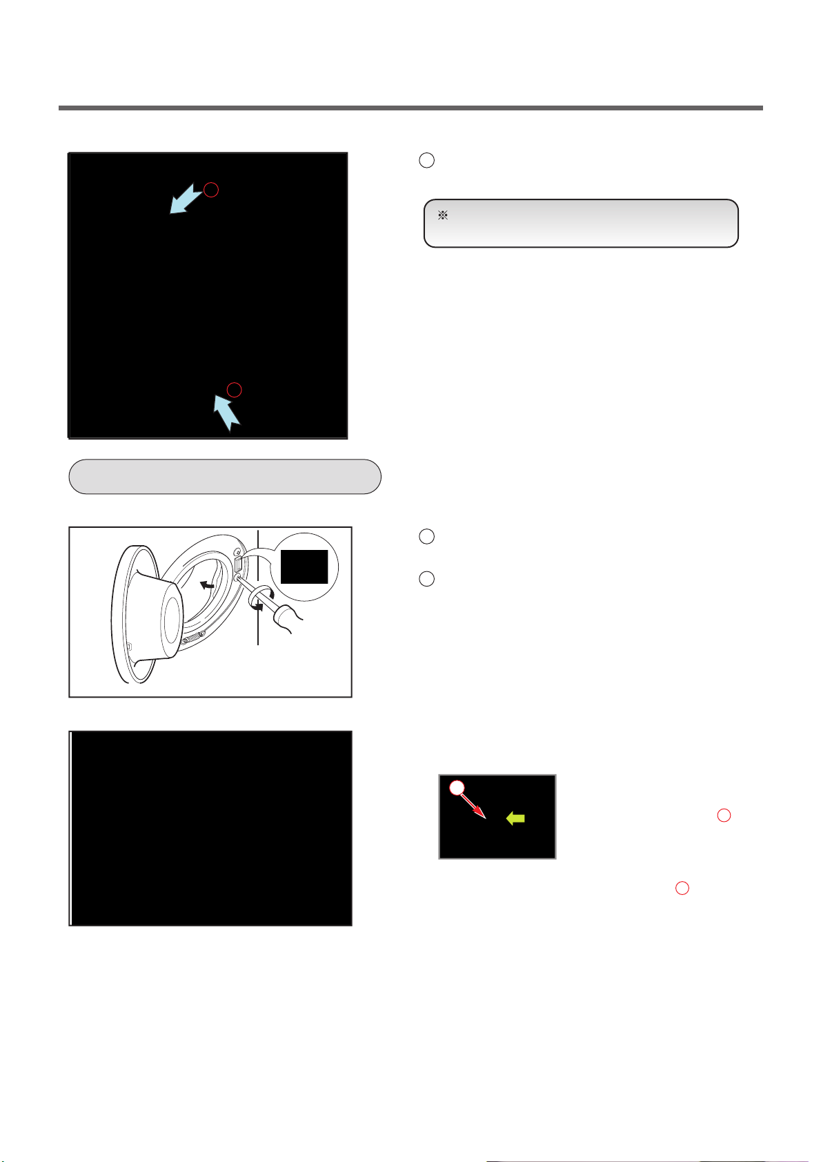
PWB ASSEMBLY(MAIN)
56
1
Unscrew two screw of the PWB
2
First Disassembly atomizing hose from the
PWB and Pull the PWB assembly in direction
of red arrow
3
Disassembly PWB like the picture
DISPENSER ASSEMBLY
1
The plate assembly(Top) are disassembled.
2
Pull the drawer to arrow direction.
3
Two screws are unscrewed.
4
Clamp
5
Cutting cable ties and the ventillation hose
are disassembly on the dispenser
Page 51

INLET VALVE
1
Disconnect the wiring connector.
2
Remove the valve by two screws of the valve
holder.
When reconnecting the connector
DOOR
VALVE (
VALVE
Rating : 220/240V 50/60Hz
Resistant : 3.5~4.5 k
1
Open the door completely.
2
Remove the three screws from the hinge.
When removing the Door Assembly, it is
necessary to hold the Bracket that is inner of
the Cabinet Cover.
1
PRE-WASH)
2
(NORMAL-WASH)
WHITE/BLACK-BLACK
or GRAY-BLACK
GRA Y/BLACK
Removing method of remained water
Pull it out from hose.
First, prepare a bucket to put in the remained
water.
CAP(REMAING HOSE)
Page 52

CABINET COVER
1
The plate assembly(Top) is disassembled.
2
Pull out the drawer and unscrew 2 screws.
3
Lift the side the Control Panel Assembly and
pull it out
1
Two screws are unscrewed.
2
Push out PANEL ASSEMBLY, CONTROL after
Push the hook( , ) below.
3
Unscrew the screws from the lower cover.
2
1
2
Disassembly cap cover and pump case.
3
Unscrew the screw from the CABINET COVER.
Remove gasket clamp and release gasket from
④
cabinet cover.
Page 53
4
1
2
59
Lift and separate the cabinet cover.
SWITCH ASSY, DOOR LOCK
NOTE:
When assembling the CABINET
COVER, connect the Door S/W connector.
1
Two screws are unscrewed and disassembly
cabinet cover.
2
The Door Lock S/W is disconnected form the
wiring connector and the strap.
• Just check cut-off.
• Check the operating time.
1
* Door Locking time : 1~8 sec.
Check the time between from
input the power to parts
move up, then Door locked.
*
Door Releasing time : 25~100 sec.
Check the time between from off
the power to parts
move down, then Door released.
1
1
Page 54

ROTOR ASSEMBLY, STATOR ASSEMBLY, FRICTION DAMPER
1
Remove the back cover.
2
After loosening the bolt, Rotor, pull out the
rotor.
1
Remove the 6 bolts from the stator.
2
Disconnect the 2 connectors.
Motor Stator
V ~ U (8~11 )
U ~ W (8~11 )
W ~ V (8~11 )
1
Remove the hinges (Damper) at the Tub.
2
The Hinge(Damper) at the base is pulled off by
pressing on the snaps at the sharp end.
3
The hinge at the base is pulled off.
(In directions of the arrow)
U V W
Page 55

Bellows
61
Pump
Hose
PUMP
Circulation
Hose
1
Disassembly Top Plate, Control Panel,
Drawer Panel Assembly, Cabinet Cover
Assembly, Lower Cover Assembly
4
Remove pump outlet hose.
5
Remove tub pump bellows.
6
Remove cap(Remaining Hose).
7
Disconnect the wiring.
8
Three screws are unscrewed from the cabinet.
Remaining
Hose
HEATER
9
Remove the pump to arrow direction.
• Rating : 220/240V 50Hz
• Resistant : 162~176Ω
1
Loosen the nut.
2
Remove washing heater by pulling out.
< Heater for Washing>
• Rating : 230V 2000W
• Resistant : 24.5~28.5Ω
CAUTION
When assembling the washing heater, insert
the heater to heater clip on the bottom of tub
and check the position of wire color.
Page 56

WHEN FOREIGN OBJECT STUCK BETWEEN DRUM AND TUB
62
1
Remove washing heater.
2
Remove the foreign object(wire,coin,etc) by
inserting long bar in the hole.
Page 57

10. EXPLOD ED VIEW AND PART LIST
10 -1. THE PART LIST O F CABINET ASSEMBLY
A131
A140
A134
A150
A154
A151
A141
A152
A103
A106
A102
A104
A110
A101
A100
A303
A133
A276
A440
COLD (BLUE)
A130
A485
A310
A135
A430
A410
A201
A200
A220
Page 58

11-2. THE EXPLODED VIEW OF CONTROL PANEL &
DISPENSER ASSEMBLY
F225
F300
F220
F462
F321
F160
F432
F430
F441
F215
F120
A450
F110
F210
Page 59

10-3 T HE EXPLODED VIEW OF
F140
K411
K410
F320
F310
F466
K141
F464
K111
K110
DRUM & TUB ASSEMBLY
K350 K360 K143
K123
K122K121
K125
K320
K140
K510
K340
K131
F468
K530
K130
K135
K115
K105
K410
K610
K611
K150
F467
K346
K349
F461
K520 K540
K550
Page 60

59
P/No.: MFL69040516
 Loading...